JP5600719B2 - Developing member, process cartridge, and electrophotographic apparatus - Google Patents
Developing member, process cartridge, and electrophotographic apparatus Download PDFInfo
- Publication number
- JP5600719B2 JP5600719B2 JP2012229478A JP2012229478A JP5600719B2 JP 5600719 B2 JP5600719 B2 JP 5600719B2 JP 2012229478 A JP2012229478 A JP 2012229478A JP 2012229478 A JP2012229478 A JP 2012229478A JP 5600719 B2 JP5600719 B2 JP 5600719B2
- Authority
- JP
- Japan
- Prior art keywords
- structural formula
- resin
- developing member
- structure represented
- surface layer
- Prior art date
- Legal status (The legal status is an assumption and is not a legal conclusion. Google has not performed a legal analysis and makes no representation as to the accuracy of the status listed.)
- Active
Links
Images


Classifications
-
- G—PHYSICS
- G03—PHOTOGRAPHY; CINEMATOGRAPHY; ANALOGOUS TECHNIQUES USING WAVES OTHER THAN OPTICAL WAVES; ELECTROGRAPHY; HOLOGRAPHY
- G03G—ELECTROGRAPHY; ELECTROPHOTOGRAPHY; MAGNETOGRAPHY
- G03G15/00—Apparatus for electrographic processes using a charge pattern
- G03G15/06—Apparatus for electrographic processes using a charge pattern for developing
- G03G15/08—Apparatus for electrographic processes using a charge pattern for developing using a solid developer, e.g. powder developer
- G03G15/0806—Apparatus for electrographic processes using a charge pattern for developing using a solid developer, e.g. powder developer on a donor element, e.g. belt, roller
- G03G15/0818—Apparatus for electrographic processes using a charge pattern for developing using a solid developer, e.g. powder developer on a donor element, e.g. belt, roller characterised by the structure of the donor member, e.g. surface properties
-
- G—PHYSICS
- G03—PHOTOGRAPHY; CINEMATOGRAPHY; ANALOGOUS TECHNIQUES USING WAVES OTHER THAN OPTICAL WAVES; ELECTROGRAPHY; HOLOGRAPHY
- G03G—ELECTROGRAPHY; ELECTROPHOTOGRAPHY; MAGNETOGRAPHY
- G03G5/00—Recording members for original recording by exposure, e.g. to light, to heat, to electrons; Manufacture thereof; Selection of materials therefor
- G03G5/14—Inert intermediate or cover layers for charge-receiving layers
- G03G5/147—Cover layers
- G03G5/14708—Cover layers comprising organic material
-
- C—CHEMISTRY; METALLURGY
- C08—ORGANIC MACROMOLECULAR COMPOUNDS; THEIR PREPARATION OR CHEMICAL WORKING-UP; COMPOSITIONS BASED THEREON
- C08G—MACROMOLECULAR COMPOUNDS OBTAINED OTHERWISE THAN BY REACTIONS ONLY INVOLVING UNSATURATED CARBON-TO-CARBON BONDS
- C08G18/00—Polymeric products of isocyanates or isothiocyanates
- C08G18/06—Polymeric products of isocyanates or isothiocyanates with compounds having active hydrogen
- C08G18/08—Processes
- C08G18/10—Prepolymer processes involving reaction of isocyanates or isothiocyanates with compounds having active hydrogen in a first reaction step
-
- C—CHEMISTRY; METALLURGY
- C08—ORGANIC MACROMOLECULAR COMPOUNDS; THEIR PREPARATION OR CHEMICAL WORKING-UP; COMPOSITIONS BASED THEREON
- C08G—MACROMOLECULAR COMPOUNDS OBTAINED OTHERWISE THAN BY REACTIONS ONLY INVOLVING UNSATURATED CARBON-TO-CARBON BONDS
- C08G18/00—Polymeric products of isocyanates or isothiocyanates
- C08G18/06—Polymeric products of isocyanates or isothiocyanates with compounds having active hydrogen
- C08G18/28—Polymeric products of isocyanates or isothiocyanates with compounds having active hydrogen characterised by the compounds used containing active hydrogen
- C08G18/40—High-molecular-weight compounds
- C08G18/48—Polyethers
- C08G18/4825—Polyethers containing two hydroxy groups
-
- C—CHEMISTRY; METALLURGY
- C08—ORGANIC MACROMOLECULAR COMPOUNDS; THEIR PREPARATION OR CHEMICAL WORKING-UP; COMPOSITIONS BASED THEREON
- C08G—MACROMOLECULAR COMPOUNDS OBTAINED OTHERWISE THAN BY REACTIONS ONLY INVOLVING UNSATURATED CARBON-TO-CARBON BONDS
- C08G18/00—Polymeric products of isocyanates or isothiocyanates
- C08G18/06—Polymeric products of isocyanates or isothiocyanates with compounds having active hydrogen
- C08G18/28—Polymeric products of isocyanates or isothiocyanates with compounds having active hydrogen characterised by the compounds used containing active hydrogen
- C08G18/40—High-molecular-weight compounds
- C08G18/48—Polyethers
- C08G18/4854—Polyethers containing oxyalkylene groups having four carbon atoms in the alkylene group
-
- C—CHEMISTRY; METALLURGY
- C08—ORGANIC MACROMOLECULAR COMPOUNDS; THEIR PREPARATION OR CHEMICAL WORKING-UP; COMPOSITIONS BASED THEREON
- C08G—MACROMOLECULAR COMPOUNDS OBTAINED OTHERWISE THAN BY REACTIONS ONLY INVOLVING UNSATURATED CARBON-TO-CARBON BONDS
- C08G18/00—Polymeric products of isocyanates or isothiocyanates
- C08G18/06—Polymeric products of isocyanates or isothiocyanates with compounds having active hydrogen
- C08G18/70—Polymeric products of isocyanates or isothiocyanates with compounds having active hydrogen characterised by the isocyanates or isothiocyanates used
- C08G18/72—Polyisocyanates or polyisothiocyanates
- C08G18/74—Polyisocyanates or polyisothiocyanates cyclic
- C08G18/76—Polyisocyanates or polyisothiocyanates cyclic aromatic
- C08G18/7614—Polyisocyanates or polyisothiocyanates cyclic aromatic containing only one aromatic ring
- C08G18/7621—Polyisocyanates or polyisothiocyanates cyclic aromatic containing only one aromatic ring being toluene diisocyanate including isomer mixtures
-
- C—CHEMISTRY; METALLURGY
- C08—ORGANIC MACROMOLECULAR COMPOUNDS; THEIR PREPARATION OR CHEMICAL WORKING-UP; COMPOSITIONS BASED THEREON
- C08G—MACROMOLECULAR COMPOUNDS OBTAINED OTHERWISE THAN BY REACTIONS ONLY INVOLVING UNSATURATED CARBON-TO-CARBON BONDS
- C08G18/00—Polymeric products of isocyanates or isothiocyanates
- C08G18/06—Polymeric products of isocyanates or isothiocyanates with compounds having active hydrogen
- C08G18/70—Polymeric products of isocyanates or isothiocyanates with compounds having active hydrogen characterised by the isocyanates or isothiocyanates used
- C08G18/72—Polyisocyanates or polyisothiocyanates
- C08G18/74—Polyisocyanates or polyisothiocyanates cyclic
- C08G18/76—Polyisocyanates or polyisothiocyanates cyclic aromatic
- C08G18/7657—Polyisocyanates or polyisothiocyanates cyclic aromatic containing two or more aromatic rings
- C08G18/7664—Polyisocyanates or polyisothiocyanates cyclic aromatic containing two or more aromatic rings containing alkylene polyphenyl groups
- C08G18/7671—Polyisocyanates or polyisothiocyanates cyclic aromatic containing two or more aromatic rings containing alkylene polyphenyl groups containing only one alkylene bisphenyl group
-
- C—CHEMISTRY; METALLURGY
- C09—DYES; PAINTS; POLISHES; NATURAL RESINS; ADHESIVES; COMPOSITIONS NOT OTHERWISE PROVIDED FOR; APPLICATIONS OF MATERIALS NOT OTHERWISE PROVIDED FOR
- C09D—COATING COMPOSITIONS, e.g. PAINTS, VARNISHES OR LACQUERS; FILLING PASTES; CHEMICAL PAINT OR INK REMOVERS; INKS; CORRECTING FLUIDS; WOODSTAINS; PASTES OR SOLIDS FOR COLOURING OR PRINTING; USE OF MATERIALS THEREFOR
- C09D175/00—Coating compositions based on polyureas or polyurethanes; Coating compositions based on derivatives of such polymers
- C09D175/04—Polyurethanes
- C09D175/08—Polyurethanes from polyethers
-
- G—PHYSICS
- G03—PHOTOGRAPHY; CINEMATOGRAPHY; ANALOGOUS TECHNIQUES USING WAVES OTHER THAN OPTICAL WAVES; ELECTROGRAPHY; HOLOGRAPHY
- G03G—ELECTROGRAPHY; ELECTROPHOTOGRAPHY; MAGNETOGRAPHY
- G03G15/00—Apparatus for electrographic processes using a charge pattern
- G03G15/75—Details relating to xerographic drum, band or plate, e.g. replacing, testing
- G03G15/751—Details relating to xerographic drum, band or plate, e.g. replacing, testing relating to drum
-
- Y—GENERAL TAGGING OF NEW TECHNOLOGICAL DEVELOPMENTS; GENERAL TAGGING OF CROSS-SECTIONAL TECHNOLOGIES SPANNING OVER SEVERAL SECTIONS OF THE IPC; TECHNICAL SUBJECTS COVERED BY FORMER USPC CROSS-REFERENCE ART COLLECTIONS [XRACs] AND DIGESTS
- Y10—TECHNICAL SUBJECTS COVERED BY FORMER USPC
- Y10T—TECHNICAL SUBJECTS COVERED BY FORMER US CLASSIFICATION
- Y10T428/00—Stock material or miscellaneous articles
- Y10T428/31504—Composite [nonstructural laminate]
- Y10T428/31551—Of polyamidoester [polyurethane, polyisocyanate, polycarbamate, etc.]
-
- Y—GENERAL TAGGING OF NEW TECHNOLOGICAL DEVELOPMENTS; GENERAL TAGGING OF CROSS-SECTIONAL TECHNOLOGIES SPANNING OVER SEVERAL SECTIONS OF THE IPC; TECHNICAL SUBJECTS COVERED BY FORMER USPC CROSS-REFERENCE ART COLLECTIONS [XRACs] AND DIGESTS
- Y10—TECHNICAL SUBJECTS COVERED BY FORMER USPC
- Y10T—TECHNICAL SUBJECTS COVERED BY FORMER US CLASSIFICATION
- Y10T428/00—Stock material or miscellaneous articles
- Y10T428/31504—Composite [nonstructural laminate]
- Y10T428/31855—Of addition polymer from unsaturated monomers
Description
本発明は、複写機、プリンターあるいはファクシミリの受信装置の如き電子写真方式を採用した装置に組み込まれる、感光体に接触または近接させて使用される現像部材に関する。また、本発明は、プロセスカートリッジおよび電子写真装置に関する。 The present invention relates to a developing member used in contact with or close to a photosensitive member, which is incorporated in an apparatus employing an electrophotographic system such as a copying machine, a printer, or a facsimile receiving apparatus. The present invention also relates to a process cartridge and an electrophotographic apparatus.
電子写真方式を用いた複写機やファクシミリやプリンターにおいては、感光体が帯電手段により帯電され、レーザーにより静電潜像を形成する。次に、現像容器内のトナーがトナー供給ローラ及びトナー規制部材により現像部材上に塗布され、感光体と現像部材との接触部または近接でトナーによる現像が行われる。その後、感光体上のトナーは、転写手段により記録紙に転写され、熱と圧力により定着され、感光体上に残留したトナーはクリーニングブレードによって除かれる。 In a copying machine, facsimile, or printer using an electrophotographic system, a photosensitive member is charged by a charging unit, and an electrostatic latent image is formed by a laser. Next, the toner in the developing container is applied onto the developing member by the toner supply roller and the toner regulating member, and development with the toner is performed at or near the contact portion between the photosensitive member and the developing member. Thereafter, the toner on the photoconductor is transferred onto a recording sheet by a transfer unit and fixed by heat and pressure, and the toner remaining on the photoconductor is removed by a cleaning blade.
非磁性一成分接触現像方式の画像形成装置には、感光体を帯電させたり、静電潜像を現像するため、103〜1010Ω・cmの電気抵抗を有する弾性部材が用いられている。本方式では、互いに圧接されている現像部材から電子写真感光体(ドラム)へトナーを移動させて静電潜像を現像し、トナー像が形成される。 In the non-magnetic one-component contact development type image forming apparatus, an elastic member having an electric resistance of 10 3 to 10 10 Ω · cm is used to charge a photoreceptor or develop an electrostatic latent image. . In this method, toner is moved from the developing members that are in pressure contact with each other to the electrophotographic photosensitive member (drum) to develop the electrostatic latent image, and a toner image is formed.
近年、電子写真方式を採用した装置に使用される現像部材に必要とされる性能はより高度になっており、高画質性、高耐久性の観点から、弾性層の表面に表面層を設けた二層系の現像部材が多く用いられるようになっている。 In recent years, the performance required for developing members used in apparatuses employing an electrophotographic system has become higher, and a surface layer is provided on the surface of the elastic layer from the viewpoint of high image quality and high durability. Two-layer developing members are often used.
そして、表面層には、優れた耐磨耗性、および、トナーへの帯電付与性を与えることのできるウレタン樹脂を含有させることが広く行われてきている。また、近年は、帯電部材のより一層の高機能化を図るべく、表面層の改良処方が提案されている。 The surface layer has been widely used to contain a urethane resin capable of imparting excellent wear resistance and charge imparting properties to the toner. In recent years, an improved formulation for the surface layer has been proposed in order to further increase the functionality of the charging member.
特許文献1では、ウレタン樹脂にアクリル樹脂を含有させ、耐摩耗性や摺動性を向上させることが開示されている。 Patent Document 1 discloses that an acrylic resin is contained in a urethane resin to improve wear resistance and slidability.
また、特許文献2では、ポリエーテル系ウレタン樹脂に対し、所定の物性を有するアクリル樹脂を含有させ、高温高湿度環境下でのトナー付着を抑制することが開示されている。
Further,
ところで、電子写真装置は世界各地で使用されてきていることから、多様な環境の下でも安定して高画質の電子写真画像を長期に亘って出力し得ることが求められている。そのためには、現像部材としては、低温低湿環境(例えば、気温15℃、相対湿度10%)下においても、表面にトナーの固着、すなわち、フィルミングが生じにくいものであることが必要である。 By the way, since the electrophotographic apparatus has been used all over the world, it is required to stably output a high-quality electrophotographic image over a long period of time even under various environments. For this purpose, it is necessary that the developing member be one in which toner adheres to the surface, that is, filming hardly occurs even in a low-temperature and low-humidity environment (for example, an air temperature of 15 ° C. and a relative humidity of 10%).
また、電子写真画像のより一層の高品質化のために、現像部材に対して高電圧を印加する電子写真プロセスが想定されるようになってきている。このような電子写真プロセスに用いられる現像部材としては、適当な導電性を有すると共に、高電圧(例えば、DC500V程度)を印加された場合にもリークを生じない、耐リーク性に優れた表面層を備えていることが必要である。表面層からのリークが発生した場合、表面層には通電破壊跡が発生すると共に、電子写真画像には当該リークの発生に起因する横スジ状の濃度ムラが生じ得る。ここで、表面層に導電性を付与するために、表面層中のバインダー樹脂にカーボンブラックに代表される電子導電性フィラーを分散させた場合において、電子導電性フィラーのバインダー樹脂への分散が不十分であると、表面層中に電子導電性フィラーの凝集部分が生じ、当該凝集部分においてリークが発生する場合がある。 In order to further improve the quality of an electrophotographic image, an electrophotographic process in which a high voltage is applied to a developing member has been assumed. As a developing member used in such an electrophotographic process, the surface layer has an appropriate conductivity and does not cause a leak even when a high voltage (for example, about DC 500 V) is applied, and has an excellent leak resistance. It is necessary to have. When a leak from the surface layer occurs, an energization breakdown trace occurs in the surface layer, and horizontal streak-like density unevenness due to the occurrence of the leak can occur in the electrophotographic image. Here, in order to impart conductivity to the surface layer, when an electronic conductive filler represented by carbon black is dispersed in the binder resin in the surface layer, the dispersion of the electronic conductive filler into the binder resin is not good. If it is sufficient, an agglomerated portion of the electron conductive filler is generated in the surface layer, and a leak may occur in the agglomerated portion.
本発明の目的は、低温低湿環境下であってもフィルミングが生じにくく、かつ、耐リーク性にも優れた現像部材を提供することにある。 An object of the present invention is to provide a developing member that is unlikely to cause filming even in a low-temperature and low-humidity environment and that has excellent leak resistance.
また、本発明の他の目的は、高品位な電子写真画像を安定して出力できる電子写真装置及びそれに用いられるプロセスカートリッジを提供する点にある。 Another object of the present invention is to provide an electrophotographic apparatus capable of stably outputting a high-quality electrophotographic image and a process cartridge used therefor.
本発明者らは上記の目的を達成すべく鋭意検討を重ねた。その結果、特定の構造を有する2種の樹脂と電子導電性フィラーとを表面層に含有させることにより、上記の目的を良く達成できることを見出し、本発明を為すに至った。
すなわち、本発明によれば、
導電性の基体と、該基体の上に形成された弾性層と、該弾性層の表面を被覆している表面層とを有し、該表面層は、第1の樹脂、第2の樹脂および電子導電性フィラーを含有し、
該第1の樹脂は、
隣接する2つのウレタン結合の間に、
下記構造式(1)で示される構造と、
下記構造式(2)で示される構造および下記構造式(3)で示される構造から選ばれる一方または両方の構造と、を有するものであり、
該第2の樹脂は、
下記構造式(4)で示される構造と、
下記構造式(5)で示される構造および下記構造式(6)で示される構造から選ばれる一方または両方の構造と、を有するものである現像部材が提供される。

That is, according to the present invention,
A conductive base; an elastic layer formed on the base; and a surface layer covering a surface of the elastic layer. The surface layer includes a first resin, a second resin, and Contains an electronically conductive filler,
The first resin is
Between two adjacent urethane bonds,
A structure represented by the following structural formula (1);
One or both of structures selected from the structure represented by the following structural formula (2) and the structure represented by the following structural formula (3),
The second resin is
A structure represented by the following structural formula (4);
There is provided a developing member having one or both of a structure represented by the following structural formula (5) and a structure represented by the following structural formula (6).
また、本発明によれば、現像部材が装着されてなり、電子写真装置に着脱可能なプロセスカートリッジにおいて、該現像部材が上記の現像部材であるプロセスカートリッジが提供される。 In addition, according to the present invention, there is provided a process cartridge having a developing member attached thereto and detachable from an electrophotographic apparatus, wherein the developing member is the above-described developing member.
さらに、本発明によれば、潜像を担持する感光体に対向した状態でトナーを担持する現像部材を備え、該現像部材が前記感光体にトナーを付与することにより該潜像を可視化する電子写真装置において、該現像部材が上記の現像部材である電子写真装置が提供される。 Further, according to the present invention, there is provided a developing member that bears toner in a state of being opposed to the photosensitive member that bears the latent image, and the developing member applies the toner to the photosensitive member to visualize the latent image. In the photographic apparatus, an electrophotographic apparatus is provided in which the developing member is the above-described developing member.
本発明によれば、特定の構造単位を有するウレタン樹脂とアクリル樹脂とを含有する表面層を形成することにより、柔軟で耐フィルミング性に優れ、かつ高い導電性を有しながら耐リーク性に優れる高品位の現像部材が得られる。 According to the present invention, by forming a surface layer containing a urethane resin having a specific structural unit and an acrylic resin, the film is flexible and excellent in filming resistance, and has high conductivity and leak resistance. An excellent high-quality developing member can be obtained.
また、本発明によれば、高品位な電子写真画像の安定的な提供に資するプロセスカートリッジ、及び電子写真装置が得られる。 In addition, according to the present invention, a process cartridge and an electrophotographic apparatus that contribute to stable provision of high-quality electrophotographic images can be obtained.
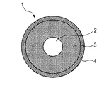
本発明に係るローラ形状の現像部材(以降、「現像ローラ」ともいう)1は、図1に示すように、円柱状または中空円筒状の導電性の基体2の上に弾性層3が形成され、弾性層3の表面を表面層4が被覆している導電性部材から構成される。
A roller-shaped developing member (hereinafter also referred to as “developing roller”) 1 according to the present invention has an
<基体>
導電性の基体2は、現像ローラ1の電極および支持部材として機能するものである。具体的な材質の例としては、アルミニウム、銅合金、ステンレス鋼の如き金属または合金;クロム、又はニッケルで鍍金処理を施した鉄;導電性を有する合成樹脂等が挙げられる。
<Substrate>
The
<弾性層>
弾性層3は、感光体表面に形成された静電潜像にトナーを過不足なく供給することができるように、適切なニップ幅とニップ圧をもって感光体に押圧されるような硬度や弾性を、現像ローラに付与するものである。弾性層3は、通常ゴム材の成型体により形成されることが好ましい。ゴム材料としては以下のものが挙げられる。エチレン−プロピレン−ジエン共重合ゴム(EPDM)、アクリルニトリル−ブタジエンゴム(NBR)、クロロプレンゴム(CR)、天然ゴム(NR)、イソプレンゴム(IR)、スチレン−ブタジエンゴム(SBR)、フッ素ゴム、シリコーンゴム、エピクロロヒドリンゴム、NBRの水素化物、ウレタンゴム。これらは単独であるいは2種以上を混合して用いることができる。
この中でも、特に、長期に亘り他の部材(現像剤規制ブレード等)が当接した場合にも圧縮永久歪みを弾性層に生じさせにくいシリコーンゴムが好ましい。シリコーンゴムとしては、ポリジメチルシロキサン、ポリメチルトリフルオロプロピルシロキサン、ポリメチルビニルシロキサン、ポリフェニルビニルシロキサン、これらポリシロキサンの共重合体が挙げられる。
<Elastic layer>
The
Among these, in particular, a silicone rubber that does not easily cause compression set in the elastic layer even when another member (developer regulating blade or the like) abuts over a long period of time is preferable. Examples of the silicone rubber include polydimethylsiloxane, polymethyltrifluoropropylsiloxane, polymethylvinylsiloxane, polyphenylvinylsiloxane, and copolymers of these polysiloxanes.
弾性層3の厚さの目安としては、1.5〜5.0mm、特には、2.0〜4.0mmの範囲にあることが好ましい。
As a guideline for the thickness of the
弾性層3中には、導電性付与剤、非導電性充填剤、架橋剤、触媒の如き各種添加剤が適宜配合される。導電性付与剤としては、カーボンブラック;アルミニウム、銅の如き導電性金属;酸化亜鉛、酸化錫、酸化チタンの如き導電性金属酸化物の微粒子を用いることができる。このうち、カーボンブラックは比較的容易に入手でき、良好な導電性が得られるので特に好ましい。
導電性付与剤としてカーボンブラックを用いる場合における、ゴム材中のカーボンブラックの含有量の目安としては、ゴム100質量部に対して10〜80質量部とすることが好ましい。非導電性充填剤としては、シリカ、石英粉末、酸化チタン、酸化亜鉛又は炭酸カルシウムが挙げられる。架橋剤としては、ジ−t−ブチルパーオキサイド、2,5−ジメチル−2,5−ジ(t−ブチルパーオキシ)ヘキサン又はジクミルパーオキサイドが挙げられる。
In the
When carbon black is used as the conductivity-imparting agent, the content of carbon black in the rubber material is preferably 10 to 80 parts by mass with respect to 100 parts by mass of rubber. Non-conductive fillers include silica, quartz powder, titanium oxide, zinc oxide or calcium carbonate. Examples of the crosslinking agent include di-t-butyl peroxide, 2,5-dimethyl-2,5-di (t-butylperoxy) hexane, and dicumyl peroxide.
<表面層>
本発明に係る表面層は、特定の構造を有する2種の樹脂と、カーボンブラックに代表される電子導電性フィラーとを含有している。
<Surface layer>
The surface layer according to the present invention contains two kinds of resins having a specific structure and an electronic conductive filler typified by carbon black.
<<第1の樹脂>>
本発明に係る第1の樹脂は、隣接する2つのウレタン結合の間に下記構造式(1)で示される構造と、下記構造式(2)で示される構造および下記構造式(3)で示される構造から選ばれる一方または両方の構造とを有するウレタン樹脂である。
すなわち、本発明に係るウレタン樹脂は、下記構造式(1)で示される構造と、下記構造式(2)で示される構造および下記構造式(3)で示される構造からなる群から選択される何れか一方または両方の構造とが、2つのウレタン結合によって挟まれている構造を分子内に有する。
The first resin according to the present invention has a structure represented by the following structural formula (1), a structure represented by the following structural formula (2), and a structure represented by the following structural formula (3) between two adjacent urethane bonds. A urethane resin having one or both of the structures selected from the above structures.
That is, the urethane resin according to the present invention is selected from the group consisting of a structure represented by the following structural formula (1), a structure represented by the following structural formula (2), and a structure represented by the following structural formula (3). Either one or both structures have a structure sandwiched by two urethane bonds in the molecule.
図6および図7に本発明に係るウレタン樹脂が有する特徴的な構造の一部を示す。
図6においては、前記構造式(1)で示される構造と前記構造式(2)で示される構造とが、隣接するウレタン結合A1及びA2によって挟まれている。
また、図7に係るウレタン樹脂においては、隣接しているウレタン結合B1とB2とによって、および、隣接するウレタン結合C1とC2とによって、前記構造式(1)で示される構造と前記構造式(2)で示される構造とが挟まれている。なお、図6および図7において、p、q、mおよびnは各々独立に正の整数を表す。
上記した第1の樹脂としてのウレタン樹脂は、上記構造式(1)で示されるポリエーテル成分を含むため、柔軟性に優れる。また、上記構造式(2)で示される構造および上記構造式(3)で示される構造から選択される少なくとも一方を含むことにより、低温域での結晶性が著しく低くなっている。そのため、本発明に係るウレタン樹脂を含む表面層を具備する現像部材は、低温環境下でも硬度が上昇し難くなっており、低温環境下でもトナーに与えるストレスが小さく、フィルミングを生じにくい。
6 and 7 show part of the characteristic structure of the urethane resin according to the present invention.
In FIG. 6, the structure represented by the structural formula (1) and the structure represented by the structural formula (2) are sandwiched between adjacent urethane bonds A1 and A2.
In the urethane resin according to FIG. 7, the structure represented by the structural formula (1) and the structural formula (1) are defined by the adjacent urethane bonds B1 and B2 and the adjacent urethane bonds C1 and C2. The structure shown in 2) is sandwiched. In FIGS. 6 and 7, p, q, m and n each independently represent a positive integer.
The urethane resin as the first resin described above is excellent in flexibility because it includes the polyether component represented by the structural formula (1). Further, by including at least one selected from the structure represented by the structural formula (2) and the structure represented by the structural formula (3), the crystallinity in the low temperature region is remarkably lowered. Therefore, the developing member having the surface layer containing the urethane resin according to the present invention is less likely to increase in hardness even under a low temperature environment, and stress applied to the toner is small even under a low temperature environment, and filming is unlikely to occur.
さらに、構造式(2)で示される構造および構造式(3)で示される構造は、構造式(1)で示される構造よりも疎水性が高い。そのため、本発明に係るウレタン樹脂は、水との親和性が低下し、ウレタン樹脂としては、比較的に低吸水性とすることができる。更に、高温域においては、構造式(2)または構造式(3)で示される構造中の、側鎖としてのメチル基の存在により高温域での分子運動性が抑制される。そのため、本発明に係る現像ローラの表面は、高温高湿環境下においても粘着性が上昇しにくく、高温高湿環境下での現像ローラ表面へのトナーの固着をも有効に抑制し得る。 Furthermore, the structure represented by the structural formula (2) and the structure represented by the structural formula (3) are more hydrophobic than the structure represented by the structural formula (1). Therefore, the urethane resin according to the present invention has a low affinity with water, and the urethane resin can have relatively low water absorption. Furthermore, in the high temperature range, the molecular mobility in the high temperature range is suppressed due to the presence of a methyl group as a side chain in the structure represented by the structural formula (2) or the structural formula (3). Therefore, the surface of the developing roller according to the present invention is less likely to increase the adhesiveness even in a high temperature and high humidity environment, and the toner can be effectively prevented from sticking to the developing roller surface in a high temperature and high humidity environment.
本発明に係るウレタン樹脂としては、上記構造式(1)で示される構造と、上記構造式(2)および構造式(3)で示される構造から選ばれる少なくとも一方とがランダムに共重合されてなるものが好ましい。また、本発明に係るウレタン樹脂中、「構造式(1)で示される構造のモル数」:「構造式(2)で示される構造および構造式(3)で示される構造のモル数の総和」は、50:50〜80:20であることが好ましい。上記したように、本発明に係るウレタン樹脂をランダム共重合体とすること、および、各構造のモル比を上記の数値範囲内とすることは、当該ウレタン樹脂の低温域での結晶性のより一層の低減、および、高温域での分子運動性のより一層の抑制を図る上で有効である。 As the urethane resin according to the present invention, the structure represented by the structural formula (1) and at least one selected from the structures represented by the structural formula (2) and the structural formula (3) are randomly copolymerized. Is preferred. In the urethane resin according to the present invention, “the number of moles of the structure represented by the structural formula (1)”: “the sum of the number of moles of the structure represented by the structural formula (2) and the structure represented by the structural formula (3)”. Is preferably 50:50 to 80:20. As described above, making the urethane resin according to the present invention a random copolymer and making the molar ratio of each structure within the above numerical range is more than the crystallinity of the urethane resin in the low temperature range. This is effective for further reduction and further suppression of molecular mobility at high temperatures.
上記したように、本発明に係るウレタン樹脂は、低温環境下においても硬度が上昇しにくいという特性を有するため、本発明に係る1つの目的である、表面へのトナーのフィルミングの抑制を達成する上で極めて有効な材料といえる。 As described above, since the urethane resin according to the present invention has a characteristic that the hardness hardly increases even under a low temperature environment, one object according to the present invention is achieved, which is suppression of toner filming on the surface. This is an extremely effective material.
しかしながら、本発明者らの更なる検討の結果、上記のウレタン樹脂に対するカーボンブラックの分散性が十分でなかった。そして、耐リーク性に優れた現像部材を得る上では、本発明に係るウレタン樹脂に対するカーボンブラックの分散性の改善を図る必要があることを認識した。 However, as a result of further studies by the present inventors, the dispersibility of carbon black in the urethane resin was not sufficient. And in order to obtain the developing member excellent in leak resistance, it recognized that it was necessary to aim at the improvement of the dispersibility of carbon black with respect to the urethane resin which concerns on this invention.
ここで、本発明に係るウレタン樹脂に対するカーボンブラックの分散性が十分でない理由を本発明者らは以下のように考察した。
一般に、ウレタン樹脂は、ポリオール鎖等からなるソフトセグメントと、ウレタン結合部分からなり、強い凝集力を有するハードセグメントとのミクロ相分離構造を有することが知られている。
特に、本発明に係るウレタン樹脂における、式(1)で示される構造と、式(2)および式(3)から選択される少なくとも一方で示される構造とを有するソフトセグメントは、極性が極めて低く、ウレタン結合からなるハードセグメントとの間での極性の差が大きい。そのため、ソフトセグメントとハードセグメントとのミクロ相分離の程度がより大きくなる傾向にある。
ウレタン樹脂へのカーボンブラックの分散には、ウレタン結合部分とカーボンブラックの表面官能基との高い親和性に基づく相互作用が大きく寄与している。しかし、本発明に係るウレタン樹脂においては、上記したように、ハードセグメントとソフトセグメントとの大きな極性差により、ハードセグメント部分が高度に凝集しているものと考えられる。そのため、ハードセグメントとカーボンブラックとの相互作用が阻害され、その結果として、カーボンブラックのウレタン樹脂中への分散が不十分となっているものと考えられる。
Here, the present inventors considered the reason why the dispersibility of carbon black in the urethane resin according to the present invention is not sufficient as follows.
In general, it is known that a urethane resin has a microphase separation structure of a soft segment composed of a polyol chain or the like and a hard segment composed of a urethane bond portion and having a strong cohesive force.
In particular, the soft segment having the structure represented by the formula (1) and the structure represented by at least one selected from the formula (2) and the formula (3) in the urethane resin according to the present invention has extremely low polarity. The difference in polarity between the hard segment made of urethane bond is large. Therefore, the degree of microphase separation between the soft segment and the hard segment tends to be larger.
The dispersion based on the high affinity between the urethane bond portion and the surface functional group of the carbon black greatly contributes to the dispersion of the carbon black in the urethane resin. However, in the urethane resin according to the present invention, as described above, it is considered that the hard segment portion is highly aggregated due to a large polarity difference between the hard segment and the soft segment. For this reason, the interaction between the hard segment and the carbon black is inhibited, and as a result, it is considered that the dispersion of the carbon black in the urethane resin is insufficient.
そこで、本発明者らは、ハードセグメントとソフトセグメントとの高度な相分離状態を解し、ウレタン結合部分とカーボンブラックとの相互作用を促すことが、本発明に係るウレタン樹脂中へのカーボンブラックの良好な分散性に有効であると考えた。そして、本発明者らは、ソフトセグメントとハードセグメントの双方に親和性を有する部分を有する樹脂として、後述する特定のアクリル樹脂を第二の樹脂として、表面層中に、本発明に係るウレタン樹脂およびカーボンブラックと共に共存させたところ、当該ウレタン樹脂中へのカーボンブラックの分散性を改善できることを見出した。 Therefore, the present inventors solved the advanced phase separation state of the hard segment and the soft segment, and promoted the interaction between the urethane bond portion and the carbon black, so that the carbon black in the urethane resin according to the present invention was It was considered effective for good dispersibility. And as a resin having a portion having affinity for both the soft segment and the hard segment, the present inventors use a specific acrylic resin described later as the second resin, and the urethane resin according to the present invention in the surface layer. And coexisting with carbon black, it was found that the dispersibility of carbon black in the urethane resin can be improved.
[主鎖ポリオールの説明]
表面層に含有されるウレタン樹脂は、隣接する2つのウレタン結合の間に下記構造式(1)で示される構造と、下記構造式(2)で示される構造および下記構造式(3)で示される構造から選ばれる一方または両方の構造を有する:
The urethane resin contained in the surface layer is represented by the structure represented by the following structural formula (1), the structure represented by the following structural formula (2), and the following structural formula (3) between two adjacent urethane bonds. Having one or both structures selected from:
本発明に係るウレタン樹脂は、例えば、テトラヒドロフランと3−メチルテトラヒドロフランを開環共重合して得られるポリエーテルポリオールとイソシアネートとを反応させることで得られる。なお、構造式(2)および構造式(3)は、何れも、3−メチルテトラヒドロフランを開環共重合させた際に生じる構造である。
また、本発明に係るウレタン樹脂は、構造式(1)の構造と、構造式(2) および(3)から選ばれる少なくとも一つの構造を有するポリエーテルジオールまたは該ポリエーテルジオールと芳香族ジイソシアネートを反応させた水酸基末端プレポリマーと、該ポリエーテルジオールと芳香族イソシアネートを反応させたイソシアネート基末端プレポリマーとを熱硬化することにより得られるものとすることが好ましい。
The urethane resin according to the present invention can be obtained, for example, by reacting a polyether polyol obtained by ring-opening copolymerization of tetrahydrofuran and 3-methyltetrahydrofuran with isocyanate. In addition, structural formula (2) and structural formula (3) are structures generated when 3-methyltetrahydrofuran is subjected to ring-opening copolymerization.
Further, the urethane resin according to the present invention comprises a polyether diol having at least one structure selected from the structure of the structural formula (1) and the structural formulas (2) and (3), or the polyether diol and an aromatic diisocyanate. It is preferable to obtain the resulting hydroxyl group-terminated prepolymer and the isocyanate group-terminated prepolymer obtained by reacting the polyether diol and aromatic isocyanate by thermosetting.
通常、ポリウレタンの合成には、以下の如き方法が用いられる。
すなわち、ポリオール成分とポリイソシアネート成分を混合、反応させるワンショット法および一部のポリオールとイソシアネートを反応させて得られるイソシアネート基末端プレポリマーと、低分子ジオール、低分子トリオールの如き鎖延長剤とを反応させる方法がある。
Usually, the following methods are used for the synthesis of polyurethane.
That is, a one-shot method in which a polyol component and a polyisocyanate component are mixed and reacted, an isocyanate group-terminated prepolymer obtained by reacting some polyol and isocyanate, and a chain extender such as a low-molecular diol or a low-molecular triol. There is a method of reacting.
しかし、構造式(1)の構造と、および構造式(2)及び構造式(3)から選ばれる少なくとも一つの構造とを有するポリエーテルジオールは極性が低い材料である。そのため、極性の高いイソシアネートとの相溶性が低く、ウレタン樹脂内において、ポリオールの比率の高い部分と、イソシアネートの比率が高い部分とにミクロの相分離を生じやすい。ポリオールの比率の高い部分は未反応成分が残存しやすく、残留する未反応ポリオールの染み出しにより表面トナー固着の原因となる場合がある。 However, the polyether diol having the structure of the structural formula (1) and at least one structure selected from the structural formula (2) and the structural formula (3) is a low-polarity material. Therefore, the compatibility with a highly polar isocyanate is low, and in the urethane resin, micro phase separation is likely to occur between a portion having a high polyol ratio and a portion having a high isocyanate ratio. Unreacted components are likely to remain in the portion where the ratio of polyol is high, and the remaining unreacted polyol may ooze out and cause surface toner fixation.
未反応ポリオールの残留は、高極性のイソシアネートを過剰に使用することで低減させることができるが、その結果として得られるウレタン樹脂は、吸水率が高いものになる。また前述した従来のウレタン樹脂の合成方法のいずれも、イソシアネート同士の反応が高い比率で起こる場合が多く、高極性であるウレア結合、アロファネート結合を生じる。 The residual unreacted polyol can be reduced by using an excessively high-polar isocyanate, but the resulting urethane resin has a high water absorption rate. In any of the conventional methods for synthesizing urethane resins described above, the reaction between isocyanates often occurs at a high ratio, resulting in a highly polar urea bond or allophanate bond.
一方、構造式(1)の構造と、構造式(2)および(3)から選ばれる少なくとも一つの構造を有するポリエーテルジオールまたは該ポリエーテルジオールと芳香族ジイソシアネートを反応させた水酸基末端プレポリマーと、該ポリエーテルジオールと芳香族イソシアネートを反応させたイソシアネート基末端プレポリマーとを熱硬化させることにより、ポリオールとイソシアネートとの極性差を小さくすることができる。 On the other hand, a structure of the structural formula (1) and a polyether diol having at least one structure selected from the structural formulas (2) and (3) or a hydroxyl group-terminated prepolymer obtained by reacting the polyether diol with an aromatic diisocyanate The polarity difference between the polyol and the isocyanate can be reduced by thermally curing the isocyanate group-terminated prepolymer obtained by reacting the polyether diol with the aromatic isocyanate.
そのためポリオールとイソシアネートの相溶性を向上させ、従来例より少ないイソシアネート比率で、より極性の低いポリウレタンが得られる。さらに未反応ポリオールの残留を非常に低く抑えることが可能であるため、未反応ポリオールの染み出しによる表面トナー固着を抑制することができる。 Therefore, the compatibility between the polyol and the isocyanate is improved, and a polyurethane having a lower polarity can be obtained with a smaller isocyanate ratio than the conventional example. Furthermore, since it is possible to keep the unreacted polyol remaining very low, it is possible to suppress surface toner adhesion due to seepage of the unreacted polyol.
構造式(1)の構造、および構造式(2)または(3)の構造からなるポリエーテルジオールを芳香族ジイソシアネートと反応させた水酸基末端プレポリマーとして使用する場合、プレポリマーの数平均分子量としては10000以上15000以下が好ましい。 When the polyether diol having the structure of the structural formula (1) and the structure of the structural formula (2) or (3) is used as a hydroxyl group-terminated prepolymer reacted with an aromatic diisocyanate, the number average molecular weight of the prepolymer is: 10,000 or more and 15000 or less are preferable.
またイソシアネート基末端プレポリマーとして使用する際は、プレポリマーのイソシアネート含有量が3.0質量%から4.0質量%の範囲にあることが好ましい。水酸基末端プレポリマーの分子量、イソシアネート基末端プレポリマーのイソシアネート含有量がこの範囲にあると、生成するポリウレタンの低吸水率化と未反応成分の残留抑制のバランスが良く、トナーの固着のより一層の抑制に資する。 Moreover, when using as an isocyanate group terminal prepolymer, it is preferable that the isocyanate content of a prepolymer exists in the range of 3.0 mass% to 4.0 mass%. When the molecular weight of the hydroxyl group-terminated prepolymer and the isocyanate content of the isocyanate group-terminated prepolymer are within this range, the resulting polyurethane has a good balance of water absorption and residual suppression of unreacted components, and the toner can be more firmly fixed. Contribute to restraint.
また、本発明に係るポリウレタンは、下記(a)の水酸基末端プレポリマーと、下記(b)のイソシアネート基末端プレポリマーとを熱硬化させたものであることがより好ましい。
(a)構造式(1)の構造、および構造式(2)及び(3)から選ばれる少なくとも一つの構造からなる数平均分子量2000以上3000以下のポリエーテルジオールと芳香族ジイソシアネートを反応させた数平均分子量10000以上15000以下の水酸基末端プレポリマー。
(b)構造式(1)の構造、および構造式(2)及び(3)から選ばれる少なくとも一つの構造からなる数平均分子量2000以上3000以下のポリエーテルジオールと芳香族イソシアネートを反応させたイソシアネート基末端プレポリマー。
The polyurethane according to the present invention is more preferably one obtained by thermally curing the hydroxyl group-terminated prepolymer (a) below and the isocyanate group-terminated prepolymer (b) below.
(A) Number of reaction between a polyether diol having a number average molecular weight of 2000 or more and 3000 or less and an aromatic diisocyanate comprising the structure of the structural formula (1) and at least one structure selected from the structural formulas (2) and (3) Hydroxyl-terminated prepolymer having an average molecular weight of 10,000 to 15,000.
(B) Isocyanate obtained by reacting an aromatic isocyanate with a polyether diol having a number average molecular weight of 2000 or more and 3000 or less comprising the structure of the structural formula (1) and at least one structure selected from the structural formulas (2) and (3) Base terminal prepolymer.
数平均分子量2000以上3000以下の該ポリエーテルジオールを、水酸基末端プレポリマーおよびイソシアネート基末端プレポリマーの原料として用いると、最終的に得られるポリウレタンの低吸水率化を図ることができ、また未反応成分の残留を抑制することができる。さらに表面層の強度と粘着性にも優れるため、耐久性も向上することができる。 When the polyether diol having a number average molecular weight of 2000 or more and 3000 or less is used as a raw material for the hydroxyl group-terminated prepolymer and the isocyanate group-terminated prepolymer, the water absorption of the finally obtained polyurethane can be reduced, and unreacted Residual components can be suppressed. Furthermore, since the strength and adhesiveness of the surface layer are excellent, the durability can be improved.
2つのウレタン結合の間には、構造式(1)の構造と、構造式(2)および(3)から選ばれる少なくとも一つの構造以外に、本発明の効果が損なわれない程度に、必要に応じてポリプロピレングリコール、脂肪族ポリエステルを含有してもよい。
脂肪族ポリエステルとしては、1,4−ブタンジオール、3−メチル−1,5−ペンタンジオール、ネオペンチルグリコールの如きジオール成分、トリメチロールプロパンの如きトリオール成分と、アジピン酸、グルタル酸、セバシン酸等のジカルボン酸との縮合反応により得られる脂肪族ポリエステルポリオールが挙げられる。
Between the two urethane bonds, other than the structure of the structural formula (1) and at least one structure selected from the structural formulas (2) and (3), it is necessary to the extent that the effects of the present invention are not impaired. Accordingly, polypropylene glycol and aliphatic polyester may be contained.
Aliphatic polyesters include 1,4-butanediol, 3-methyl-1,5-pentanediol, diol components such as neopentyl glycol, triol components such as trimethylolpropane, adipic acid, glutaric acid, sebacic acid, etc. Aliphatic polyester polyols obtained by condensation reaction with dicarboxylic acids.
これらのポリオール成分は必要に応じてあらかじめ2,4−トリレンジイソシアネート(TDI)、1,4−ジフェニルメタンジイソシアネート(MDI)、イソホロンジイソシアネート(IPDI)の如きイソシアネートにより鎖延長したプレポリマーとしてもよい。 These polyol components may be prepolymers that are chain-extended with an isocyanate such as 2,4-tolylene diisocyanate (TDI), 1,4-diphenylmethane diisocyanate (MDI), or isophorone diisocyanate (IPDI) as required.
構造式(1)の構造と、構造式(2)および(3)から選ばれる少なくとも一つの構造以外の成分は、本発明の効果発現の観点から、ポリウレタン中、20質量%以下の含有率とすることが好ましい。 Components other than the structure of the structural formula (1) and at least one structure selected from the structural formulas (2) and (3) have a content of 20% by mass or less in the polyurethane from the viewpoint of the effect of the present invention. It is preferable to do.
これらのポリオール成分と反応させるイソシアネート化合物としては、特に限定されるものではないが、エチレンジイソシアネート、1,6−ヘキサメチレンジイソシアネート(HDI)の如き脂肪族ポリイソシアネート、イソホロンジイソシアネート(IPDI)、シクロヘキサン1,3−ジイソシアネート、シクロヘキサン1,4−ジイソシアネートの如き脂環式ポリイソシアネート、2,4−トリレンジイソシアネート、2,6−トリレンジイソシアネート(TDI)、4,4−ジフェニルメタンジイソシアネート(MDI)、ポリメリックジフェニルメタンジイソシアネート、キシリレンジイソシアネート、ナフタレンジイソシアネートの如き芳香族イソシアネート及びこれらの共重合物やイソシアヌレート体、TMPアダクト体、ビウレット体、そのブロック体を用いることができる。 The isocyanate compound to be reacted with these polyol components is not particularly limited, but aliphatic polyisocyanates such as ethylene diisocyanate, 1,6-hexamethylene diisocyanate (HDI), isophorone diisocyanate (IPDI), cyclohexane 1, 3-diisocyanate, cycloaliphatic polyisocyanate such as cyclohexane 1,4-diisocyanate, 2,4-tolylene diisocyanate, 2,6-tolylene diisocyanate (TDI), 4,4-diphenylmethane diisocyanate (MDI), polymeric diphenylmethane diisocyanate Aromatic isocyanates such as xylylene diisocyanate and naphthalene diisocyanate, copolymers thereof, isocyanurates, TMP adducts, Uretto body, it is possible to use the block body.
この中でもトリレンジイソシアネート、ジフェニルメタンジイソシアネート、ポリメリックジフェニルメタンジイソシアネートの如き芳香族イソシアネートがより好適に用いられる。 Among these, aromatic isocyanates such as tolylene diisocyanate, diphenylmethane diisocyanate, and polymeric diphenylmethane diisocyanate are more preferably used.
芳香族イソシアネートとウレタン結合同士の間に、構造式(1)と、構造式(2)および(3)から選ばれる少なくとも一つの構造を有するポリエーテル成分とを反応させて得られるポリウレタンは、柔軟かつ強度に優れ、高温高湿下で粘着性が低いため好ましい。 A polyurethane obtained by reacting a structural component (1) with a polyether component having at least one structure selected from structural formulas (2) and (3) between an aromatic isocyanate and a urethane bond is flexible. In addition, it is excellent in strength and has low adhesiveness under high temperature and high humidity, which is preferable.
ポリオール成分と反応させるイソシアネート化合物の混合比は、ポリオールの水酸基1.0に対してイソシアネート基の比率が1.2から4.0の範囲であることが好ましい。 The mixing ratio of the isocyanate compound to be reacted with the polyol component is preferably such that the ratio of isocyanate groups is 1.2 to 4.0 with respect to 1.0 hydroxyl groups of the polyol.
一般に、ウレタン樹脂は、ポリオール成分が凝集したソフトセグメントと、イソシアネート成分が凝集したハードセグメントにミクロに相分離している。 In general, a urethane resin is microscopically phase-separated into a soft segment in which a polyol component is aggregated and a hard segment in which an isocyanate component is aggregated.
特に、本発明に係るウレタン樹脂は、ソフトセグメントとハードセグメントとの極性差が大きくなる傾向にあり、一般的なウレタン樹脂と比較して、ソフトセグメントとハードセグメントとの相分離の度合いがより大きくなる傾向にある。 In particular, the urethane resin according to the present invention tends to have a large polarity difference between the soft segment and the hard segment, and the degree of phase separation between the soft segment and the hard segment is larger than that of a general urethane resin. Tend to be.
そして、イソシアネート成分は、カーボンブラックのごとき導電性フィラーの表面と親和性が高いため、導電性フィラーの表面と相互作用し、分散安定性に寄与していると考えられる。このイソシアネート成分の凝集度が著しく高い場合、導電性フィラー表面に均一に吸着安定化しにくくなることで分散性が低下し、耐リーク性を低下させる場合があると考えられる。
ところで、シリコーンゴムを含む弾性層の表面に接して、上記第1の樹脂を含む表面層を設けた場合、該表面層と該弾性層とは、高温高湿環境下に長期間放置した場合においても良好な接着性を示す。通常、合成樹脂同士の接着性は、化学結合に加えて、水素結合、酸−塩基相互作用のような、主に極性官能基の相互作用に依存する。しかし、シリコーンゴムは非常に極性が低く、その表面は不活性である。そのため、一般に、シリコーンゴムを含む弾性層とポリウレタン樹脂を含む表面層との接着性に関して、極性官能基による強い相互作用は期待できない。しかしながら、本発明に係る第1の樹脂を含む表面層は、シリコーンゴムを含む弾性層とは、苛酷な高温高湿環境下においても良好な接着性を示す。その詳細な理由は現在解明中であるが、本発明者らは以下のように推測している。
すなわち、隣接するウレタン結合間に存在する構造式(1)で示される構造と、構造式(2)で示される構造および構造式(3)で示される構造からなる群から選ばれる少なくとも一つの構造とを有するウレタン樹脂は、従来のポリエーテルポリウレタンと比較して、メチル基を側鎖に導入したことにより、ポリウレタンとしては非常に低極性となっている。一方、付加硬化型ジメチルシリコーンゴムの硬化物は、シロキサン(Si−O)結合が6個で1回転する「らせん状」の分子構造を有しており、かつ、メチル基が外側に配向していることが知られている。つまり、シリコーンゴムのポリマー鎖の表面は、疎水性のメチル基で実質的に被覆されている。そのため、本発明に係る弾性層中のシリコーンゴム表面のメチル基と、表面層中のウレタン樹脂中の隣接する2つのウレタン結合の間に導入された側鎖としてのメチル基との間に疎水性の分子間に働く引力が作用している。その結果として、本発明に係る表面層と弾性層とは優れた接着性を示すものと考えられる。
And since the isocyanate component has high affinity with the surface of a conductive filler such as carbon black, it is considered that the isocyanate component interacts with the surface of the conductive filler and contributes to dispersion stability. When the aggregation degree of this isocyanate component is remarkably high, it is considered that the dispersibility is lowered due to difficulty in uniformly adsorbing and stabilizing the surface of the conductive filler, and the leakage resistance may be lowered.
By the way, when the surface layer containing the first resin is provided in contact with the surface of the elastic layer containing silicone rubber, the surface layer and the elastic layer are left in a high temperature and high humidity environment for a long time. Also exhibits good adhesion. Usually, the adhesion between synthetic resins depends mainly on the interaction of polar functional groups such as hydrogen bonds and acid-base interactions in addition to chemical bonds. However, silicone rubber is very low in polarity and its surface is inert. For this reason, generally, a strong interaction due to polar functional groups cannot be expected with respect to the adhesiveness between the elastic layer containing silicone rubber and the surface layer containing polyurethane resin. However, the surface layer containing the first resin according to the present invention exhibits good adhesion to the elastic layer containing silicone rubber even in a severe high-temperature and high-humidity environment. Although the detailed reason is currently being elucidated, the present inventors speculate as follows.
That is, at least one structure selected from the group consisting of the structure represented by Structural Formula (1) existing between adjacent urethane bonds, the structure represented by Structural Formula (2), and the structure represented by Structural Formula (3) Compared with the conventional polyether polyurethane, the urethane resin having the above has a very low polarity as a polyurethane by introducing a methyl group into the side chain. On the other hand, the cured product of addition-curing dimethyl silicone rubber has a “spiral” molecular structure in which there are six siloxane (Si—O) bonds and one rotation, and the methyl group is oriented outward. It is known that That is, the surface of the silicone rubber polymer chain is substantially covered with a hydrophobic methyl group. Therefore, hydrophobicity is present between the methyl group on the surface of the silicone rubber in the elastic layer according to the present invention and the methyl group as a side chain introduced between two adjacent urethane bonds in the urethane resin in the surface layer. The attractive force acting between the molecules is acting. As a result, it is considered that the surface layer and the elastic layer according to the present invention exhibit excellent adhesion.
<<第2の樹脂>>
本発明に係る第2の樹脂は、
下記構造式(4)で示される構造と、
下記構造式(5)で示される構造および下記構造式(6)で示される構造から選ばれる一方または両方の構造とを有するアクリル樹脂である。以降、第2の樹脂を単に「アクリル樹脂」とも称する。
The second resin according to the present invention is:
A structure represented by the following structural formula (4);
An acrylic resin having a structure represented by the following structural formula (5) and one or both structures selected from the structure represented by the following structural formula (6). Hereinafter, the second resin is also simply referred to as “acrylic resin”.
上記した本発明に係るアクリル樹脂が含有する構造式(4)は、(メタ)アクリル酸の短鎖アルキルエステルであり、前記した第1の樹脂のソフトセグメントを構成する、構造式(1)、(2)および(3)で表されるポリエーテル構造と親和性が高い。一方、本発明に係るアクリル樹脂が含む構造式(5)および(6)は芳香環を有し、第1の樹脂のハードセグメントを構成しているウレタン結合と親和性を有する。すなわち、第2の樹脂は、第1の樹脂のソフトセグメントおよびハードセグメントの双方に親和性を有する。そのため、第2の樹脂を第1の樹脂と共存させた場合、第1の樹脂のソフトセグメントとハードセグメントとの間の相分離の傾向が抑制されるものと考えられる。その結果、ハードセグメントを構成しているウレタン結合の凝集が解れ、ウレタン結合と電子導電性フィラーとの相互作用が生じやすくなり、表面層中における電子導電性フィラーの分散性が向上するものと考えられる。 Structural formula (4) contained in the acrylic resin according to the present invention is a short-chain alkyl ester of (meth) acrylic acid, and constitutes the soft segment of the first resin described above, High affinity with the polyether structures represented by (2) and (3). On the other hand, the structural formulas (5) and (6) included in the acrylic resin according to the present invention have an aromatic ring and have an affinity for the urethane bond constituting the hard segment of the first resin. That is, the second resin has affinity for both the soft segment and the hard segment of the first resin. Therefore, it is considered that when the second resin coexists with the first resin, the tendency of phase separation between the soft segment and the hard segment of the first resin is suppressed. As a result, the aggregation of the urethane bonds constituting the hard segment is released, the interaction between the urethane bonds and the electronic conductive filler is likely to occur, and the dispersibility of the electronic conductive filler in the surface layer is improved. It is done.
第2の樹脂において、「構造式(4)のモル数:構造式(5)及び構造式(6)のモル数の総和」の比率としては、20:80〜80:20であることが好ましい。 In the second resin, the ratio of “the number of moles of the structural formula (4): the total number of moles of the structural formula (5) and the structural formula (6)” is preferably 20:80 to 80:20. .
構造式(4)中、R2は炭素数1以上4以下の直鎖または分岐を有するアルキル基である。R2が炭素数1以上4以下の直鎖または分岐したアルキル基であることにより、第1の樹脂のソフトセグメントとの良好な親和性が維持される。 In Structural Formula (4), R 2 is a linear or branched alkyl group having 1 to 4 carbon atoms. When R2 is a linear or branched alkyl group having 1 to 4 carbon atoms, good affinity with the soft segment of the first resin is maintained.
アクリル樹脂中に、構造式(4)の構造を与えるモノマーの具体例を以下に挙げる。メチル(メタ)アクリレート、エチル(メタ)アクリレート、n−プロピル(メタ)アクリレート、n−ブチル(メタ)アクリレート、イソプロピル(メタ)アクリレート、sec−ブチル(メタ)アクリレート、イソブチル(メタ)アクリレート、tert−ブチル(メタ)アクリレート、が挙げられる。なお、「(メタ)アクリレート」はメタクリレートあるいはアクリレートを意味する(以下、同様)。 Specific examples of monomers that give the structure of the structural formula (4) in the acrylic resin are given below. Methyl (meth) acrylate, ethyl (meth) acrylate, n-propyl (meth) acrylate, n-butyl (meth) acrylate, isopropyl (meth) acrylate, sec-butyl (meth) acrylate, isobutyl (meth) acrylate, tert- And butyl (meth) acrylate. "(Meth) acrylate" means methacrylate or acrylate (hereinafter the same).
構造式(5)中のR3、および構造式(6)中のR6は、水素原子の他に、炭素数1以上4以下の直鎖または分岐を有するアルキル基であってもよい。また構造式(6)中のR5は炭素数1以上4以下のアルキレン基である。これにより、第1の樹脂のハードセグメントとの良好な親和性が維持される。 R 3 in Structural Formula (5) and R 6 in Structural Formula (6) may be a straight or branched alkyl group having 1 to 4 carbon atoms in addition to a hydrogen atom. R 5 in Structural Formula (6) is an alkylene group having 1 to 4 carbon atoms. Thereby, good affinity with the hard segment of the first resin is maintained.
当該アクリル樹脂中に、構造式(5)の構造を与えるモノマーの具体例を以下に挙げる。スチレン、4−(または3−)メチルスチレン、4−(または3−)エチルスチレン、4−(または3−)n−プロピルスチレン、4−(または3−)n−ブチルスチレン、4−(または3−)イソプロピルスチレン、4−(または3−)sec−ブチルスチレン、4−(または3−)イソブチルスチレン、4−(または3−)tert−ブチルスチレン、が挙げられる。 Specific examples of the monomer that gives the structure of the structural formula (5) in the acrylic resin are given below. Styrene, 4- (or 3-) methylstyrene, 4- (or 3-) ethylstyrene, 4- (or 3-) n-propylstyrene, 4- (or 3-) n-butylstyrene, 4- (or 3-) isopropyl styrene, 4- (or 3-) sec-butyl styrene, 4- (or 3-) isobutyl styrene, 4- (or 3-) tert-butyl styrene.
当該アクリル樹脂中に、構造式(6)の構造を与えるモノマーの具体例を以下に挙げる。
ベンジル(メタ)アクリレート、4−(または3−)メチルベンジル(メタ)アクリレート、4−(または3−)エチルベンジル(メタ)アクリレート、4−(または3−)n−プロピルベンジル(メタ)アクリレート、4−(または3−)n−ブチルベンジル(メタ)アクリレート、4−(または3−)イソプロピルベンジル(メタ)アクリレート、4−(または3−)sec−ブチルベンジル(メタ)アクリレート、4−(または3−)イソブチルベンジル(メタ)アクリレート、4−(または3−)tert−ブチルベンジル(メタ)アクリレート、
フェニルエチル(メタ)アクリレート、4−(または3−)メチルフェニルエチル(メタ)アクリレート、4−(または3−)エチルフェニルエチル(メタ)アクリレート、4−(または3−)n−プロピルフェニルエチル(メタ)アクリレート、4−(または3−)n−ブチルフェニルエチル(メタ)アクリレート、4−(または3−)イソプロピルフェニルエチル(メタ)アクリレート、4−(または3−)sec−ブチルフェニルエチル(メタ)アクリレート、4−(または3−)イソブチルフェニルエチル(メタ)アクリレート、4−(または3−)tert−ブチルフェニルエチル(メタ)アクリレート、
フェニルプロピル(メタ)アクリレート、4−(または3−)メチルフェニルプロピル(メタ)アクリレート、4−(または3−)エチルフェニルプロピル(メタ)アクリレート、4−(または3−)n−プロピルフェニルプロピル(メタ)アクリレート、4−(または3−)n−ブチルフェニルプロピル(メタ)アクリレート、4−(または3−)イソプロピルフェニルプロピル(メタ)アクリレート、4−(または3−)sec−ブチルフェニルプロピル(メタ)アクリレート、4−(または3−)イソブチルフェニルプロピル(メタ)アクリレート、4−(または3−)tert−ブチルフェニルプロピル(メタ)アクリレート、
フェニルブチル(メタ)アクリレート、4−(または3−)メチルフェニルブチル(メタ)アクリレート、4−(または3−)エチルフェニルブチル(メタ)アクリレート、4−(または3−)n−プロピルフェニルブチル(メタ)アクリレート、4−(または3−)n−ブチルフェニルブチル(メタ)アクリレート、4−(または3−)イソプロピルフェニルブチル(メタ)アクリレート、4−(または3−)sec−ブチルフェニルブチル(メタ)アクリレート、4−(または3−)イソブチルフェニルブチル(メタ)アクリレート、4−(または3−)tert−ブチルフェニルブチル(メタ)アクリレート。
Specific examples of monomers that give the structure of the structural formula (6) in the acrylic resin are given below.
Benzyl (meth) acrylate, 4- (or 3-) methylbenzyl (meth) acrylate, 4- (or 3-) ethylbenzyl (meth) acrylate, 4- (or 3-) n-propylbenzyl (meth) acrylate, 4- (or 3-) n-butylbenzyl (meth) acrylate, 4- (or 3-) isopropylbenzyl (meth) acrylate, 4- (or 3-) sec-butylbenzyl (meth) acrylate, 4- (or 3-) isobutylbenzyl (meth) acrylate, 4- (or 3-) tert-butylbenzyl (meth) acrylate,
Phenylethyl (meth) acrylate, 4- (or 3-) methylphenylethyl (meth) acrylate, 4- (or 3-) ethylphenylethyl (meth) acrylate, 4- (or 3-) n-propylphenylethyl ( Meth) acrylate, 4- (or 3-) n-butylphenylethyl (meth) acrylate, 4- (or 3-) isopropylphenylethyl (meth) acrylate, 4- (or 3-) sec-butylphenylethyl (meth) ) Acrylate, 4- (or 3-) isobutylphenylethyl (meth) acrylate, 4- (or 3-) tert-butylphenylethyl (meth) acrylate,
Phenylpropyl (meth) acrylate, 4- (or 3-) methylphenylpropyl (meth) acrylate, 4- (or 3-) ethylphenylpropyl (meth) acrylate, 4- (or 3-) n-propylphenylpropyl ( Meth) acrylate, 4- (or 3-) n-butylphenylpropyl (meth) acrylate, 4- (or 3-) isopropylphenylpropyl (meth) acrylate, 4- (or 3-) sec-butylphenylpropyl (meth) ) Acrylate, 4- (or 3-) isobutylphenylpropyl (meth) acrylate, 4- (or 3-) tert-butylphenylpropyl (meth) acrylate,
Phenylbutyl (meth) acrylate, 4- (or 3-) methylphenylbutyl (meth) acrylate, 4- (or 3-) ethylphenylbutyl (meth) acrylate, 4- (or 3-) n-propylphenylbutyl ( (Meth) acrylate, 4- (or 3-) n-butylphenylbutyl (meth) acrylate, 4- (or 3-) isopropylphenylbutyl (meth) acrylate, 4- (or 3-) sec-butylphenylbutyl (meth) ) Acrylate, 4- (or 3-) isobutylphenylbutyl (meth) acrylate, 4- (or 3-) tert-butylphenylbutyl (meth) acrylate.
当該アクリル樹脂の数平均分子量は、相溶性と柔軟性の両観点から、20000以上、100000以下であることが好ましい。 The number average molecular weight of the acrylic resin is preferably 20,000 or more and 100,000 or less from the viewpoints of compatibility and flexibility.
また該アクリル樹脂の含有量はウレタン樹脂100質量部に対し、1質量部以上10質量部以下であることが好ましい。 Moreover, it is preferable that content of this acrylic resin is 1 to 10 mass parts with respect to 100 mass parts of urethane resins.
[電子導電性フィラー]
本発明の表面層を構成するウレタン樹脂は電子導電性フィラーを含有する。そして、電子導電性フィラーの具体例としては、カーボンブラックが挙げられる。
カーボンブラックは安価であり、導電付与性と補強性にも優れるため好適に用いられ、また抵抗の環境変動が少ないため特に好ましい。
耐リーク性の観点から、該カーボンブラックの性状としては一次粒子径17nm以上20nm以下のガスブラックであることが特に好ましい。
[Electron conductive filler]
The urethane resin constituting the surface layer of the present invention contains an electronic conductive filler. A specific example of the electronic conductive filler is carbon black.
Carbon black is suitable because it is inexpensive, excellent in conductivity imparting properties and reinforcing properties, and is less preferred because of less environmental fluctuations in resistance.
From the viewpoint of leakage resistance, the carbon black is particularly preferably a gas black having a primary particle diameter of 17 nm or more and 20 nm or less.
カーボンブラックのバインダー樹脂への分散性を高めるためには、通常は一次粒子径が大きいカーボンブラックを選択するが、導電性の著しい低下が起こる場合がある。 In order to improve the dispersibility of carbon black in the binder resin, carbon black having a large primary particle size is usually selected, but there may be a significant decrease in conductivity.
ガスブラックは、原料ガスを空気中で燃焼させるため表面に極性官能基を付与しやすい。また一般的に一次粒子径が小さく、かつ一次粒子径の分布が小さいため、本発明のウレタン樹脂と組み合わせると高導電性と耐リーク性を高次元で両立させることができる。 Since gas black burns source gas in the air, it is easy to give a polar functional group to the surface. Moreover, since the primary particle size is generally small and the distribution of the primary particle size is small, when combined with the urethane resin of the present invention, both high conductivity and leakage resistance can be achieved at a high level.
該カーボンブラックのDBP吸油量は80ml/100g以上160ml/100g以下であると、導電性、硬度、分散性のバランスが良好であり好ましい。カーボンブラックの含有率は、表面層を形成する総樹脂成分100質量部に対して10質量部以上30質量部以下であることが好ましい。 When the carbon black has a DBP oil absorption of 80 ml / 100 g or more and 160 ml / 100 g or less, the balance of conductivity, hardness and dispersibility is good. The content of carbon black is preferably 10 parts by mass or more and 30 parts by mass or less with respect to 100 parts by mass of the total resin components forming the surface layer.
微粒子
現像部材として表面粗度が必要な場合は、表面層に粗さ制御のための微粒子を添加してもよい。粗さ制御用微粒子としては、体積平均粒径が3〜20μmであることが好ましい。また、表面層に添加する粒子添加量が、表面層の樹脂固形分100質量部に対し、10〜100質量部であることが好ましい。粗さ制御用微粒子には、ウレタン樹脂、ポリエステル樹脂、ポリエ−テル樹脂、ポリアミド樹脂、アクリル樹脂、フェノ−ル樹脂の微粒子を用いることができる。
Fine particles When surface roughness is required as a developing member, fine particles for controlling the roughness may be added to the surface layer. The fine particles for roughness control preferably have a volume average particle size of 3 to 20 μm. Moreover, it is preferable that the particle addition amount added to a surface layer is 10-100 mass parts with respect to 100 mass parts of resin solid content of a surface layer. As the fine particles for roughness control, fine particles of urethane resin, polyester resin, polyether resin, polyamide resin, acrylic resin, phenol resin can be used.
表面層の形成方法
表面層の形成方法としては特に限定されるものではないが、塗料によるスプレー、浸漬、又はロールコートが挙げられる。浸漬塗工は、特開昭57−5047号公報に記載されているような浸漬槽上端から塗料をオーバーフローさせる方法であり、表面層を形成する方法として簡便で生産安定性に優れている。
Formation method of surface layer Although it does not specifically limit as a formation method of a surface layer, The spray by a coating material, immersion, or a roll coat is mentioned. The dip coating is a method of overflowing the paint from the upper end of the dip tank as described in JP-A-57-5047, which is simple and excellent in production stability as a method of forming a surface layer.
図4は浸漬塗工装置の概略図である。25は円筒形の浸漬槽であり、現像ローラ外径よりわずかに大きな内径を有し、現像ローラの軸方向の長さより大きな深さを有している。浸漬槽25の上縁外周には環状の液受け部が設けられており、撹拌タンク27と接続されている。また浸漬槽25の底部は撹拌タンク27と接続されている。撹拌タンク27の塗料は、液送ポンプ26によって浸漬槽25の底部に送り込まれる。浸漬槽の上端部からは、塗料がオーバーフローしており、浸漬槽25の上縁外周の液受け部を介して撹拌タンク27に戻る。弾性層を上に設けた芯体は昇降装置28に垂直に固定され、浸漬槽25中に浸漬し、引き上げることで表面層4を形成する。
FIG. 4 is a schematic view of a dip coating apparatus. A
本発明の現像ローラは、磁性一成分現像剤や非磁性一成分現像剤を用いた非接触型現像装置及び接触型現像装置や、二成分現像剤を用いた現像装置等いずれにも適用することができる。 The developing roller of the present invention can be applied to any one of a non-contact developing device and a contact developing device using a magnetic one-component developer or a non-magnetic one-component developer, a developing device using a two-component developer, and the like. Can do.
本発明のプロセスカートリッジは、少なくとも本発明の現像ローラが装着されており、電子写真装置の本体に着脱可能に構成されている。また、本発明の電子写真装置は、潜像を担持する感光体に対向した状態でトナーを担持する現像ローラを備えており、現像ローラが感光体にトナーを付与することにより潜像を可視化するものであり、現像ローラとして本発明の現像ローラを用いる。本発明の現像ローラは電子写真感光体に当接して配置されていることが好ましい。 The process cartridge of the present invention is equipped with at least the developing roller of the present invention and is configured to be detachable from the main body of the electrophotographic apparatus. The electrophotographic apparatus of the present invention further includes a developing roller that carries toner in a state of being opposed to the photosensitive member carrying the latent image, and the developing roller visualizes the latent image by applying toner to the photosensitive member. The developing roller of the present invention is used as the developing roller. The developing roller of the present invention is preferably disposed in contact with the electrophotographic photosensitive member.
本発明のプロセスカートリッジ及び電子写真装置は、上記本発明の現像ローラを有するものであれば、複写機、ファクシミリ、又はプリンターに限定されるものではない。 The process cartridge and the electrophotographic apparatus of the present invention are not limited to a copying machine, a facsimile machine, or a printer as long as they have the developing roller of the present invention.
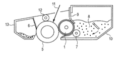
本発明の現像ローラを搭載した本発明のプロセスカートリッジ及び電子写真装置の一例として、非磁性一成分現像系プロセスを用いたプリンターを以下に説明する。図2において、現像装置10は、一成分トナーとして非磁性トナー8を収容した現像容器と、現像容器内の長手方向に延在する開口部に位置し感光体5と対向設置された現像ローラ1とを備え、感光体5上の静電潜像を現像してトナー像を形成する。
As an example of the process cartridge and the electrophotographic apparatus of the present invention equipped with the developing roller of the present invention, a printer using a non-magnetic one-component development system process will be described below. In FIG. 2, the developing
図3に示すように、プリンターには図示しない回転機構により回転される感光体5が備えられる。感光体5の周りには、感光体5の表面を所定の極性・電位に帯電させる帯電部材12と、帯電された感光体5の表面に画像露光を行って静電潜像を形成する、不図示の画像露光装置とが配置される。更に感光体5の周りには、形成された静電潜像上にトナーを付着させて現像する本発明の現像ローラ1を有する現像装置10が配置される。さらに、紙22にトナー像を転写した後、感光体5上をクリーニングする装置13が設けられる。紙22の搬送経路上には、転写されたトナー像を紙22上に定着させる定着装置15が配置される。
As shown in FIG. 3, the printer is provided with a
以下に本発明に係る具体的な実施例及び比較例について示す。 Specific examples and comparative examples according to the present invention will be described below.
−基体の用意−
基体として、SUS304製の直径6mmの芯金にプライマー(商品名、DY35−051;東レダウコーニング社製)を塗布、焼付けしたものを用意した。
-Preparation of substrate-
As a substrate, a SUS304 core metal having a diameter of 6 mm coated with a primer (trade name, DY35-051; manufactured by Toray Dow Corning) and baked was prepared.
−弾性層の形成−
上記で用意した基体を金型に配置し、以下の材料を混合した付加型シリコーンゴム組成物を金型内に形成されたキャビティに注入した。
・液状シリコーンゴム材料(商品名、SE6724A/B;東レ・ダウコーニング社製)100質量部
・カーボンブラック(商品名、トーカブラック#4300;東海カーボン社製)
15質量部
・耐熱性付与剤としてのシリカ粉体 0.2質量部
・白金触媒 0.1質量部
続いて、金型を加熱してシリコーンゴムを150℃、15分間加硫硬化し、脱型した後、さらに180℃、1時間加熱し硬化反応を完結させ、基体の外周に直径12mmの弾性層を設けた。
-Formation of elastic layer-
The substrate prepared above was placed in a mold, and an addition type silicone rubber composition in which the following materials were mixed was injected into a cavity formed in the mold.
・ Liquid silicone rubber material (trade name, SE6724A / B; manufactured by Toray Dow Corning) 100 parts by mass ・ Carbon black (trade name, Talker Black # 4300; manufactured by Tokai Carbon Co., Ltd.)
15 parts by mass / silica powder as a heat resistance imparting agent 0.2 parts by mass / 0.1 parts by mass of platinum catalyst Subsequently, the mold was heated to cure and cure the silicone rubber at 150 ° C. for 15 minutes, and then demolded. After that, it was further heated at 180 ° C. for 1 hour to complete the curing reaction, and an elastic layer having a diameter of 12 mm was provided on the outer periphery of the substrate.
−表面層の調製−
以下に、本発明に係るウレタン樹脂を含む表面層を得るための合成例を示す。
-Preparation of surface layer-
Below, the synthesis example for obtaining the surface layer containing the urethane resin which concerns on this invention is shown.
[数平均分子量の測定]
本実施例中における数平均分子量(Mn)の測定に用いた装置、並びに条件は以下の通りである。
・測定機器:HLC−8120GPC(商品名、東ソー社製);
・カラム:TSKgel SuperHZMM(商品名、東ソー社製)×2本;
・溶媒:THF;
・温度:40℃;
・THFの流速:0.6ml/min。
なお、測定サンプルは0.1質量%のTHF溶液とした。更に検出器としてRI(屈折率)検出器を用いて測定を行った。
検量線作成用の標準試料として、TSK標準ポリスチレン(商品名、A−1000、A−2500、A−5000、F−1、F−2、F−4、F−10、F−20、F−40、F−80、F−128;東ソー社製)を用いて検量線の作成を行った。これを基に得られた測定サンプルの保持時間から数平均分子量を求めた。
[Measurement of number average molecular weight]
The apparatus and conditions used for the measurement of the number average molecular weight (Mn) in this example are as follows.
Measuring instrument: HLC-8120GPC (trade name, manufactured by Tosoh Corporation);
Column: TSKgel SuperHZMM (trade name, manufactured by Tosoh Corporation) x 2 pieces;
-Solvent: THF;
-Temperature: 40 ° C;
THF flow rate: 0.6 ml / min.
The measurement sample was a 0.1% by mass THF solution. Further, an RI (refractive index) detector was used as a detector for measurement.
As a standard sample for preparing a calibration curve, TSK standard polystyrene (trade names, A-1000, A-2500, A-5000, F-1, F-2, F-4, F-10, F-20, F- 40, F-80, F-128; manufactured by Tosoh Corporation) were used to prepare a calibration curve. The number average molecular weight was determined from the retention time of the measurement sample obtained based on this.
(ポリエーテルジオール A−1の合成)
反応容器中で、乾燥テトラヒドロフラン 230.7g(3.2モル)、乾燥3−メチルテトラヒドロフラン 68.9g(0.8モル)(モル混合比80/20)の混合物を、温度10℃に保持した。70%過塩素酸13.1g、及び無水酢酸 120gを加え、2.5時間反応を行った。次に反応混合物を20%水酸化ナトリウム水溶液600g中に注ぎ、精製を行った。さらに減圧下残留する水及び溶媒成分を除去し、液状のポリエ−テルジオールA−1 218gを得た。数平均分子量は約2000であった。
(Synthesis of polyether diol A-1)
In a reaction vessel, a mixture of 230.7 g (3.2 mol) of dry tetrahydrofuran and 68.9 g (0.8 mol) of dry 3-methyltetrahydrofuran (molar mixing ratio 80/20) was maintained at a temperature of 10 ° C. 70% perchloric acid (13.1 g) and acetic anhydride (120 g) were added, and the reaction was performed for 2.5 hours. Next, the reaction mixture was poured into 600 g of a 20% aqueous sodium hydroxide solution for purification. Further, water and solvent components remaining under reduced pressure were removed to obtain 218 g of liquid polyether diol A-1. The number average molecular weight was about 2000.
(水酸基末端ポリウレタンポリオール A−2の合成)
窒素雰囲気下、反応容器中で、ジフェニルメタンジイソシアネート(商品名、コスモネートMDI:三井化学社製)28.4質量部をメチルエチルケトン 50.0質量部に溶解した。次にポリエーテルジオール A−1 200.0gのメチルエチルケトン 178.4質量部溶液を反応容器内の温度を65℃に保持しつつ、徐々に滴下した。滴下終了後、温度75℃で3時間反応させた。得られた反応混合物を室温まで冷却し、水酸基末端ウレタンプレポリマー A−2 226gを得た。数平均分子量は約15000であった。得られたポリオールを表1に示す。
(Synthesis of hydroxyl-terminated polyurethane polyol A-2)
Under a nitrogen atmosphere, 28.4 parts by mass of diphenylmethane diisocyanate (trade name, Cosmonate MDI: manufactured by Mitsui Chemicals) was dissolved in 50.0 parts by mass of methyl ethyl ketone in a reaction vessel. Next, a solution of polyether diol A-1 (200.0 g) in methyl ethyl ketone (178.4 parts by mass) was gradually added dropwise while maintaining the temperature in the reaction vessel at 65 ° C. After completion of dropping, the reaction was carried out at a temperature of 75 ° C for 3 hours. The obtained reaction mixture was cooled to room temperature to obtain 226 g of a hydroxyl group-terminated urethane prepolymer A-2. The number average molecular weight was about 15000. The obtained polyol is shown in Table 1.
(イソシアネート基末端プレポリマー B−1の合成)
窒素雰囲気下、反応容器中で、ポリメリックMDI(商品名、ミリオネートMT;日本ポリウレタン工業社製)76.7質量部をメチルエチルケトン 80.0質量部に溶解した。次にポリエーテルジオールA−1 200.0gのメチルエチルケトン 70.0質量部溶液を反応容器内の温度を65℃に保持しつつ、徐々に滴下した。滴下終了後、温度65℃で2時間反応させた。得られた反応混合物を室温まで冷却し、イソシアネート基機末端ウレタンプレポリマー B−1 229gを得た。
(Synthesis of isocyanate group-terminated prepolymer B-1)
Under a nitrogen atmosphere, 76.7 parts by mass of polymeric MDI (trade name, Millionate MT; manufactured by Nippon Polyurethane Industry Co., Ltd.) was dissolved in 80.0 parts by mass of methyl ethyl ketone in a reaction vessel. Next, a solution of polyether diol A-1 (200.0 g) in methyl ethyl ketone (70.0 parts by mass) was gradually added dropwise while maintaining the temperature in the reaction vessel at 65 ° C. After completion of the dropping, the reaction was carried out at a temperature of 65 ° C. for 2 hours. The obtained reaction mixture was cooled to room temperature to obtain 229 g of an isocyanate group-terminated urethane prepolymer B-1.
(イソシアネート基末端プレポリマー B−2の合成)
窒素雰囲気下、反応容器中でトリレンジイソシアネート(TDI)(商品名、コスモネート80;三井化学社製)69.6質量部をメチルエチルケトン 80.0質量部に溶解した。次にポリプロピレングリコール系ポリオール (商品名、エクセノール1030;旭硝子株式会社製)200.0gのメチルエチルケトン 70.0質量部溶液を反応容器内の温度を65℃に保持しつつ、徐々に滴下した。滴下終了後、温度65℃で2時間反応させた。得られた反応混合物を室温まで冷却し、イソシアネート基機末端ウレタンプレポリマー B−2 244gを得た。
(Synthesis of isocyanate group-terminated prepolymer B-2)
Under a nitrogen atmosphere, 69.6 parts by mass of tolylene diisocyanate (TDI) (trade name, Cosmonate 80; manufactured by Mitsui Chemicals) was dissolved in 80.0 parts by mass of methyl ethyl ketone in a reaction vessel. Next, a polypropylene glycol polyol (trade name, Exenol 1030; manufactured by Asahi Glass Co., Ltd.) 200.0 g of methyl ethyl ketone 70.0 parts by mass solution was gradually added dropwise while maintaining the temperature in the reaction vessel at 65 ° C. After completion of the dropping, the reaction was carried out at a temperature of 65 ° C. for 2 hours. The obtained reaction mixture was cooled to room temperature to obtain 244 g of an isocyanate group-terminated urethane prepolymer B-2.
イソシアネート基末端プレポリマーを表2に示す。 Table 2 shows the isocyanate group-terminated prepolymers.
(アクリル樹脂 C−1の合成)
撹拌装置、温度計、還流管、滴下装置および窒素ガス導入管を取り付けた反応容器に乾燥メチルエチルケトン 233.3質量部を仕込み、窒素ガス気流下で温度87℃に昇温し、加熱還流した。次にメタクリル酸メチル 60.0質量部、スチレン 40.0質量部、開始剤(商品名、カヤエステルO;化薬アクゾ社製)0.2質量部の混合物を1時間かけて徐々に滴下し、温度を87℃に保ったままさらに3時間加熱還流した。次に放冷して温度を室温まで下げ、アクリル樹脂C−1を得た。数平均分子量は約60000であった。
(Synthesis of acrylic resin C-1)
A reaction vessel equipped with a stirrer, a thermometer, a reflux tube, a dropping device, and a nitrogen gas introduction tube was charged with 233.3 parts by mass of dry methyl ethyl ketone, heated to a temperature of 87 ° C. under a nitrogen gas stream, and heated to reflux. Next, a mixture of 60.0 parts by mass of methyl methacrylate, 40.0 parts by mass of styrene, and 0.2 parts by mass of an initiator (trade name, Kayaester O; manufactured by Kayaku Akzo Co., Ltd.) is gradually dropped over 1 hour. The mixture was further heated to reflux for 3 hours while maintaining the temperature at 87 ° C. Next, it was allowed to cool and the temperature was lowered to room temperature to obtain an acrylic resin C-1. The number average molecular weight was about 60,000.
(アクリル樹脂 C−3の合成)
撹拌装置、温度計、還流管、滴下装置および窒素ガス導入管を取り付けた反応容器に乾燥メチルエチルケトン 233.3質量部を仕込み、窒素ガス気流下で温度87℃に昇温し、加熱還流した。次にメタクリル酸メチル 30.0質量部、メタクリル酸n−ブチル30.0質量部、スチレン 40.0質量部、開始剤(商品名、カヤエステルO;化薬アクゾ社製)0.2質量部の混合物を1時間かけて徐々に滴下し、温度を87℃に保ったままさらに3時間加熱還流した。次に放冷して温度を室温まで下げ、アクリル樹脂C−3を得た。数平均分子量は約70000であった。
(Synthesis of acrylic resin C-3)
A reaction vessel equipped with a stirrer, a thermometer, a reflux tube, a dropping device, and a nitrogen gas introduction tube was charged with 233.3 parts by mass of dry methyl ethyl ketone, heated to a temperature of 87 ° C. under a nitrogen gas stream, and heated to reflux. Next, 30.0 parts by mass of methyl methacrylate, 30.0 parts by mass of n-butyl methacrylate, 40.0 parts by mass of styrene, 0.2 parts by mass of an initiator (trade name, Kayaester O; manufactured by Kayaku Akzo) The mixture was gradually added dropwise over 1 hour, and the mixture was heated to reflux for 3 hours while maintaining the temperature at 87 ° C. Next, it was left to cool and the temperature was lowered to room temperature to obtain an acrylic resin C-3. The number average molecular weight was about 70000.
(アクリル樹脂 C−2、C−4〜C−14の合成)
モノマー種、モル混合比を表3のように変更した以外は同様の操作を行い、アクリル樹脂 C−2、C−4〜C−14を得た。
Except having changed the monomer seed | species and molar mixing ratio as shown in Table 3, the same operation was performed and acrylic resin C-2 and C-4-C-14 were obtained.
(実施例1)
以下に、本発明に係る現像ローラの製造法について説明する。
Example 1
Below, the manufacturing method of the developing roller which concerns on this invention is demonstrated.
表面層4の材料として、ポリオールA−1 100.0質量部に対し、イソシアネート基末端プレポリマーB−1 109.0質量部、アクリル樹脂 C−1 5.3質量部、一次粒子径20nmのガスブラック(商品名、Color Black S−160;エボニック・デグサジャパン社製)32.0質量部を撹拌混合した。
次に総固形分比30質量%になるようにメチルエチルケトン(以下、「MEK」と略す)に溶解、混合の後、サンドミルにて均一に分散し、表面層形成用塗料1を得た。ついで、この塗料を粘度10〜13cpsになるようMEKで希釈後、前記弾性層上に浸漬塗工した。その後、乾燥させ、さらに温度150℃にて1時間加熱処理することで弾性層の外周に膜厚が約20μmの表面層を設けた。こうして実施例1の現像ローラを得た。
As a material for the surface layer 4, 100.0 parts by mass of the polyol A-1 is 109.0 parts by mass of the isocyanate group-terminated prepolymer B-1, 5.3 parts by mass of the acrylic resin C-1, and a gas having a primary particle diameter of 20 nm. 32.0 parts by mass of black (trade name, Color Black S-160; manufactured by Evonik Degussa Japan) was stirred and mixed.
Next, it was dissolved in methyl ethyl ketone (hereinafter abbreviated as “MEK”) so as to have a total solid content ratio of 30 mass%, mixed and then uniformly dispersed by a sand mill to obtain a coating material 1 for forming a surface layer. Subsequently, this paint was diluted with MEK so as to have a viscosity of 10 to 13 cps, and then dip-coated on the elastic layer. Then, it was dried and further heat-treated at a temperature of 150 ° C. for 1 hour to provide a surface layer having a thickness of about 20 μm on the outer periphery of the elastic layer. Thus, the developing roller of Example 1 was obtained.
(実施例2〜10)
表面層の材料として表4に示すアクリル樹脂の種類および量としたこと以外は実施例1の表面層形成用塗料1と同様にして表面層形成用塗料2〜10を得た。そしてこれらの表面層形成用塗料を用いたこと以外は実施例1と同様にして実施例2〜10の現像ローラを得た。
(Examples 2 to 10)
Surface layer-forming
(実施例11)
水酸基末端ウレタンプレポリマー A−2 100.0質量部に対し、イソシアネート基末端プレポリマーB−1 19.1質量部、アクリル樹脂 C−3 10.1質量部、一次粒子径17nmのガスブラック(商品名、Color Black S−170;エボニック・デグサジャパン社製)12.1質量部を撹拌混合して表面層形成用塗料11を得た。表面層形成用塗料11を用いたこと以外は実施例1と同様にして、実施例11の現像ローラを得た。
(Example 11)
Hydroxyl-terminated urethane prepolymer A-2 10.1 parts by mass of isocyanate group-terminated prepolymer B-1 10.1 parts by mass of acrylic resin C-3, gas black having a primary particle diameter of 17 nm (product) Name, Color Black S-170; manufactured by Evonik Degussa Japan Co., Ltd.) 12.1 parts by mass was stirred and mixed to obtain a surface layer-forming
(実施例12)
アクリル樹脂をC−8としたこと以外は表面層形成用塗料11と同様にして表面層形成用塗料12を得た。表面層形成用塗料12を用いたこと以外は実施例1と同様にして実施例12の現像ローラを得た。
(Example 12)
A surface layer forming
(実施例13)
水酸基末端ウレタンプレポリマー A−2 100.0質量部に対し、イソシアネート基末端プレポリマーB−2 20.9質量部、アクリル樹脂 C−3 10.3質量部、一次粒子径17nmのガスブラック(商品名、Color Black S−170;エボニック・デグサジャパン社製)12.3質量部を撹拌混合して表面層形成用塗料13を得た。これを用いたこと以外は実施例1と同様にして実施例13の現像ローラを得た
(Example 13)
Hydroxyl-terminated urethane prepolymer A-2 100.0 parts by mass, isocyanate group-terminated prepolymer B-2 20.9 parts by mass, acrylic resin C-3 10.3 parts by mass,
(実施例14) アクリル樹脂をC−8としたこと以外は表面層形成用塗料13と同様にして表面層形成用塗料14を得た。これを用いたこと以外は実施例1と同様にして実施例14の現像ローラを得た。
(Example 14) Surface layer forming
(実施例15)
カーボンブラックとして、一次粒子径25nmのファーネスブラック(商品名、SUNBLACK X55;旭カーボン社製)を用いたこと以外は表面層形成用塗料1と同様にして表面層形成用塗料15を得た。これを用いたこと以外は実施例1と同様にして、実施例15の現像ローラを得た。
(Example 15)
Surface layer forming
(実施例16)
カーボンブラックを、一次粒子径23nmのファーネスブラック(商品名、Printex L;エボニック・デグサジャパン社製)を用いたこと以外は表面層形成用塗料1と同様にして表面層形成用塗料16を得た。これを用いたこと以外は実施例1と同様にして実施例16の現像ローラを得た。
(Example 16)
Surface
(実施例17)
カーボンブラックとして、一次粒子径13nmのファーネスブラック(商品名、#2650;三菱化学社製)を用いたこと以外は表面層形成用塗料1と同様にして表面層形成用塗料17を得た。これを用いたこと以外は実施例1と同様にして実施例17の現像ローラを得た。
(Example 17)
Surface
なお、本発明の表面層が構造式(1)と、構造式(2)および構造式(3)から選ばれる一方または両方の構造、及び構造式(4)で示される構造と、構造式(5)で示される構造および構造式(6)で示される構造から選ばれる一方または両方の構造を有していることは、例えば熱分解GC/MS、FT−IR、13C核固体NMRによる分析により確認することが可能である。実施例で得られた各表面層を、熱分解GC/MS、FT−IRにより解析した結果、構造式(1)で示される構造と、構造式(2)で示される構造および構造式(3)、及び構造式(4)で示される構造と、構造式(5)で示される構造および構造式(6)で示される構造とを有していることが確認された。
Note that the surface layer structure (1) of the present invention, the structural formula (2) and a structure represented by the structural formula (3) one or both of the structures selected from, and structural formula (4), structural formula structure and structural formula represented by (5) to have one or both of the structures selected from the structures represented by (6), for example pyrolysis GC / MS, FT-IR, 13C nuclear solid It can be confirmed by analysis by NMR. Each surface layer obtained in Example, pyrolysis GC / MS, the results were analyzed by FT-IR, and the structure represented by the structural formula (1), the structure and structure represented by the structural formula (2) confirmed to have a structure represented by granulation formula (3), and the structural formula (4), and a structure represented by the structural formula (5) structure represented by and structural formula (6) It was done.
(比較例1〜4)
アクリル樹脂およびカーボンブラックの種類を表5に示すアクリル樹脂およびカーボンブラックの種類とした以外は、実施例13と同様にして、比較例1〜4の現像ローラを得た。
(Comparative Examples 1-4)
Developing rollers of Comparative Examples 1 to 4 were obtained in the same manner as in Example 13 except that the types of acrylic resin and carbon black were changed to the types of acrylic resin and carbon black shown in Table 5.
以上のようにして得られた実施例1〜17及び比較例1〜4の現像ローラについて以下の項目を評価した。 The following items were evaluated for the developing rollers of Examples 1 to 17 and Comparative Examples 1 to 4 obtained as described above.
[表面層の物性測定用シートの作製]
表面層形成用塗料を粘度15cpsに調整し、膜厚200μmになるようにアルミ型にキャストし、サンフラワー架台に載せ表面層形成用塗料の粘度が表面に膜形成しない程度に上昇するまで乾燥させた。その後、水平台に載せて室温下1日放置した。乾燥後、140℃で1時間加熱硬化し、室温まで冷却後、型からはがし、膜厚が約200μmの物性測定用の導電性樹脂シートを作製した。
[Preparation of sheet for measuring physical properties of surface layer]
Adjust the viscosity of the surface layer forming paint to 15 cps, cast it into an aluminum mold so that the film thickness is 200 μm, place it on a sunflower pedestal and dry it until the viscosity of the surface layer forming paint does not form a film on the surface. It was. Then, it was placed on a horizontal table and allowed to stand at room temperature for 1 day. After drying, it was heated and cured at 140 ° C. for 1 hour, cooled to room temperature, peeled off from the mold, and a conductive resin sheet for measuring physical properties having a film thickness of about 200 μm was produced.
[評価1]体積抵抗率の測定;
上記方法で作製した物性測定用の導電性樹脂シートを直径5cmの円形に打ち抜き、両面に白金蒸着を施した後、気温25℃、相対湿度50%RH環境下24時間放置した。抵抗測定機(商品名:R8340A、アドバンテスト社製)を用いて、100Vの電圧を印加して体積抵抗率を測定した。数値はn=3で測定した平均値を用いた。
[Evaluation 1] Measurement of volume resistivity;
The conductive resin sheet for measuring physical properties prepared by the above method was punched out into a circular shape having a diameter of 5 cm, and platinum was deposited on both sides, and then left for 24 hours in an environment with an air temperature of 25 ° C. and a relative humidity of 50% RH. Using a resistance measuring instrument (trade name: R8340A, manufactured by Advantest Corporation), a voltage of 100 V was applied to measure volume resistivity. As the numerical value, an average value measured at n = 3 was used.
[評価2]通電破壊限界の測定;
上記の体積抵抗率の測定の後、印加電圧を100Vずつ上げて上記した体積抵抗率の測定を繰り返し行った。そして、電圧印加時に体積抵抗値が大きく低下し、測定サンプル表面に通電による破壊跡が発生するまで試験を行い、通電破壊を生じない最大電圧を通電破壊限界とした。
[Evaluation 2] Measurement of energization breakdown limit;
After the volume resistivity measurement, the applied voltage was increased by 100 V and the volume resistivity measurement was repeated. Then, the test was conducted until the volume resistance value greatly decreased when a voltage was applied, and a breakdown trace due to energization occurred on the surface of the measurement sample, and the maximum voltage that did not cause energization breakdown was defined as the energization breakdown limit.
[評価3]現像ローラの電流値;
図5に示すように、直径40mmのSUS製円筒状電極29に、現像ローラ1の基体露出部に各500gの荷重を加え、該現像ローラ1の外周面を当接させる。この状態で円筒状電極29を回転させ、連れ周りにより、現像ローラ1を周方向に24rpmの速度で回転させる。回転が安定したところで、直流電源30より基体に電圧を印加し、円筒状電極29との間に50Vの電圧を印加する。なお、この時の環境は、20℃、50%RHとする。その時の電流計31にて電流値を現像ローラ1の1周分計測し、その平均値を求めて、電流値とした。
[Evaluation 3] Current value of developing roller;
As shown in FIG. 5, a load of 500 g is applied to the SUS
[評価4]画像評価(その1):現像ローラの耐リーク性の評価;
作製した現像ローラを、電子写真画像形成装置(商品名:Color Laser Jet3600、Hewlett−Packard社製)を用意した。また、上記電子写真画像形成装置用の黒色トナー用プロセスカートリッジを21個用意した。そして、当該プロセスカートリッジの現像ローラとして、各実施例および各比較例において作製した現像ローラを装着した。また、各プロセスカートリッジの現像剤規制ブレードを、厚さ100μmのステンレス鋼(SUS304)製の現像剤規制ブレードに交換した。さらに、現像剤規制ブレードに接続されたバイアス電源からは、現像ローラに接続されたバイアス電源から出力される電圧よりも500V低い電圧を、現像剤規制ブレードに供給して画像出力を行った。
[Evaluation 4] Image evaluation (Part 1): Evaluation of leakage resistance of the developing roller;
An electrophotographic image forming apparatus (trade name: Color Laser Jet 3600, manufactured by Hewlett-Packard Co.) was prepared for the produced developing roller. In addition, 21 process cartridges for black toner for the electrophotographic image forming apparatus were prepared. And the developing roller produced in each Example and each comparative example was mounted | worn as a developing roller of the said process cartridge. Further, the developer regulating blade of each process cartridge was replaced with a developer regulating blade made of stainless steel (SUS304) having a thickness of 100 μm. Further, the bias power source connected to the developer regulating blade supplies a voltage 500V lower than the voltage output from the bias power source connected to the developing roller to the developer regulating blade to perform image output.
上記で用意した各プロセスカートリッジを、上記電子画像形成装置ブラック用ポジションに装填し、温度15℃、湿度10%RHの環境に24時間放置した。その後、同環境において、ハーフトーン画像を1枚出力した。引き続いて、サイズが4ポイントのアルファベット「E」の文字が、A4サイズの紙上に印字率が2%となるような画像(以降、「E文字画像」と称する)を20000枚連続出力した。引き続いて、ハーフトーン画像を1枚出力した。各ハーフトーン画像について、現像剤規制ブレードと帯電ローラとの間での電流のリークに起因する横スジの有無を目視で観察した。そして、横スジが観察されたハーフトーン画像については、反射濃度計(商品名:GreatagMacbeth RD918、マクベス社製)を用いて、横スジの発生部位と正常なハーフトーン画像部との濃度差を測定した。そして、観察結果を、下記の基準に基づき評価した。
A:横スジは確認されない。
B:極軽微な横スジが確認されるが、濃度差は0.03未満である。
C:横スジが確認され、濃度差が0.05以上0.1未満である。
D:横スジが確認され、濃度差も0.1以上である。
Each of the process cartridges prepared above was loaded in the electronic image forming apparatus black position and left in an environment of a temperature of 15 ° C. and a humidity of 10% RH for 24 hours. Thereafter, one halftone image was output in the same environment. Subsequently, 20000 sheets of images (hereinafter referred to as “E character images”) in which the letter “E” having a size of 4 points has a printing rate of 2% on A4 size paper were continuously output. Subsequently, one halftone image was output. For each halftone image, the presence or absence of horizontal streaks due to current leakage between the developer regulating blade and the charging roller was visually observed. For the halftone image in which horizontal stripes were observed, the density difference between the horizontal stripe occurrence site and the normal halftone image portion was measured using a reflection densitometer (trade name: GretagMacbeth RD918, manufactured by Macbeth). did. And the observation result was evaluated based on the following reference | standard.
A: No horizontal streak is confirmed.
B: Although very slight horizontal streaks are confirmed, the density difference is less than 0.03.
C: Horizontal streaks are confirmed, and the density difference is 0.05 or more and less than 0.1.
D: Horizontal stripes are confirmed, and the density difference is 0.1 or more.
[評価5]画像評価(その2):現像ローラの耐フィルミング性の評価;
上記の画像評価(その1)にて2枚目のハーフトーン画像を出力後、さらに、E文字画像を連続出力した。そして、1000枚ごとに当該E文字画像について、現像ローラの表面にトナーがフィルミングしたことに起因する濃度ムラの有無を目視で観察した。そして、トナーのフィルミングに起因する濃度ムラが初めて確認された時点での出力枚数を記録した。
[Evaluation 5] Image evaluation (Part 2): Evaluation of filming resistance of the developing roller;
After the second halftone image was output in the above image evaluation (part 1), an E character image was continuously output. Then, with respect to the E character image every 1000 sheets, the presence or absence of density unevenness due to toner filming on the surface of the developing roller was visually observed. Then, the number of output sheets was recorded when density unevenness due to toner filming was first confirmed.
以上の結果を表6および表7に示す。 The above results are shown in Tables 6 and 7.
実施例1〜17の表面層は、本発明のウレタン樹脂に本発明の構造を有するアクリル樹脂を含有しているため、構造式(1)、(2)、(3)の構造を有するウレタンの相分離傾向が緩和されており、高い通電破壊限界を示し、耐リーク画像も良好である。 Since the surface layers of Examples 1 to 17 contain the acrylic resin having the structure of the present invention in the urethane resin of the present invention, the surface layers of the urethane having the structures of the structural formulas (1), (2), and (3) are used. The tendency of phase separation is relaxed, it shows a high current breakdown limit, and the leak-proof image is also good.
特に、一次粒子径が17nm以上20nm以下のガスブラックを用いた実施例1〜14は、導電性も高く、より高いレベルの通電破壊限界、耐リーク画像を示す。またいずれの水準においても高い耐フィルミング性を示している。 In particular, Examples 1 to 14 using gas black having a primary particle diameter of 17 nm or more and 20 nm or less also have high conductivity, and show a higher level of current breakdown limit and leak-proof images. Moreover, the filming resistance is high at any level.
それに対し表面層に、本発明の構造を有するアクリル樹脂を含有しない比較例1〜4はウレタンの相分離傾向が緩和されておらず、通電破壊限界が低く、耐リーク性の低下が認められる。 On the other hand, Comparative Examples 1 to 4 which do not contain the acrylic resin having the structure of the present invention in the surface layer do not relax the phase separation tendency of urethane, have a low current breakage limit, and a decrease in leak resistance is recognized.
1:現像ローラ
2:導電性基体
3:弾性層
4:表面層
5:感光体
6:クリーニング部材
7:トナー供給ローラ
8:トナー
9:規制ブレード
10:現像装置
11:レーザー光
12:帯電部材
13:クリーニング装置
14:クリーニング用帯電装置
15:定着装置
16:駆動ローラ
17:転写ローラ
18:バイアス電源
19:テンションローラー
20:転写搬送ベルト
21:従動ローラ
22:紙
23:給紙ローラ
24:吸着ローラ
25:浸漬槽
26:液送ポンプ
27:撹拌タンク
28:昇降装置
29:円筒状電極
30:直流電源
31:電流計
1: Developing roller 2: Conductive substrate 3: Elastic layer 4: Surface layer 5: Photoreceptor 6: Cleaning member 7: Toner supply roller 8: Toner 9: Regulator blade 10: Developing device 11: Laser beam 12: Charging member 13 : Cleaning device 14: Cleaning device 15: Fixing device 16: Driving roller 17: Transfer roller 18: Bias power supply 19: Tension roller 20: Transfer conveyor belt 21: Driven roller 22: Paper 23: Paper feed roller 24: Adsorption roller 25: immersion tank 26: liquid feed pump 27: stirring tank 28: lifting device 29: cylindrical electrode 30: DC power supply 31: ammeter
Claims (9)
該表面層は、第1の樹脂、第2の樹脂および電子導電性フィラーを含有し、
該第1の樹脂は、
隣接する2つのウレタン結合の間に、
下記構造式(1)で示される構造と、
下記構造式(2)で示される構造および下記構造式(3)で示される構造から選ばれる一方または両方の構造とを有するものであり、
該第2の樹脂は、
下記構造式(4)で示される構造と、
下記構造式(5)で示される構造および下記構造式(6)で示される構造から選ばれる一方または両方の構造とを有するものであることを特徴とする現像部材:
The surface layer contains a first resin, a second resin and an electronically conductive filler,
The first resin is
Between two adjacent urethane bonds,
A structure represented by the following structural formula (1);
One or both of structures selected from the structure represented by the following structural formula (2) and the structure represented by the following structural formula (3),
The second resin is
A structure represented by the following structural formula (4);
A developing member having one or both of structures selected from the structure represented by the following structural formula (5) and the structure represented by the following structural formula (6):
Priority Applications (6)
| Application Number | Priority Date | Filing Date | Title |
|---|---|---|---|
| JP2012229478A JP5600719B2 (en) | 2012-06-27 | 2012-10-17 | Developing member, process cartridge, and electrophotographic apparatus |
| CN201280074327.2A CN104412170B (en) | 2012-06-27 | 2012-10-18 | Developing member, handle box and electronic photographing device |
| KR1020157001336A KR101626735B1 (en) | 2012-06-27 | 2012-10-18 | Developing member, process cartridge, and electrophotographic apparatus |
| EP12880251.9A EP2869129B1 (en) | 2012-06-27 | 2012-10-18 | Development member, process cartridge, and electrophotography device |
| PCT/JP2012/006682 WO2014002152A1 (en) | 2012-06-27 | 2012-10-18 | Development member, process cartridge, and electrophotography device |
| US14/075,393 US8798508B2 (en) | 2012-06-27 | 2013-11-08 | Developing member, process cartridge, and electrophotographic apparatus |
Applications Claiming Priority (3)
| Application Number | Priority Date | Filing Date | Title |
|---|---|---|---|
| JP2012144345 | 2012-06-27 | ||
| JP2012144345 | 2012-06-27 | ||
| JP2012229478A JP5600719B2 (en) | 2012-06-27 | 2012-10-17 | Developing member, process cartridge, and electrophotographic apparatus |
Publications (3)
| Publication Number | Publication Date |
|---|---|
| JP2014029453A JP2014029453A (en) | 2014-02-13 |
| JP2014029453A5 JP2014029453A5 (en) | 2014-08-07 |
| JP5600719B2 true JP5600719B2 (en) | 2014-10-01 |
Family
ID=49782389
Family Applications (1)
| Application Number | Title | Priority Date | Filing Date |
|---|---|---|---|
| JP2012229478A Active JP5600719B2 (en) | 2012-06-27 | 2012-10-17 | Developing member, process cartridge, and electrophotographic apparatus |
Country Status (6)
| Country | Link |
|---|---|
| US (1) | US8798508B2 (en) |
| EP (1) | EP2869129B1 (en) |
| JP (1) | JP5600719B2 (en) |
| KR (1) | KR101626735B1 (en) |
| CN (1) | CN104412170B (en) |
| WO (1) | WO2014002152A1 (en) |
Families Citing this family (39)
| Publication number | Priority date | Publication date | Assignee | Title |
|---|---|---|---|---|
| JP6104068B2 (en) | 2012-06-27 | 2017-03-29 | キヤノン株式会社 | Developing member, process cartridge, and electrophotographic apparatus |
| US9442416B2 (en) * | 2013-12-26 | 2016-09-13 | Canon Kabushiki Kaisha | Image-forming apparatus, image-forming method, developing apparatus, and developing method |
| US9625854B2 (en) | 2014-06-05 | 2017-04-18 | Canon Kabushiki Kaisha | Developer carrying member, electrophotographic process cartridge, and electrophotographic image forming apparatus |
| US9482986B2 (en) | 2015-02-27 | 2016-11-01 | Canon Kabushiki Kaisha | Member for electrophotography, process cartridge, and electrophotographic image forming apparatus |
| US10197930B2 (en) | 2015-08-31 | 2019-02-05 | Canon Kabushiki Kaisha | Electrophotographic member, process cartridge, and electrophotographic apparatus |
| US10082741B2 (en) | 2015-10-06 | 2018-09-25 | Canon Kabushiki Kaisha | Member for electrophotography, developing apparatus, and electrophotographic apparatus |
| JP6860319B2 (en) | 2015-10-23 | 2021-04-14 | キヤノン株式会社 | Develop members, process cartridges and electrophotographic image forming equipment |
| JP6806579B2 (en) | 2016-02-05 | 2021-01-06 | キヤノン株式会社 | Electrophotographic components, their manufacturing methods, process cartridges and electrophotographic equipment |
| JP6815889B2 (en) | 2016-02-26 | 2021-01-20 | キヤノン株式会社 | Develop rollers, process cartridges and electrophotographic image forming equipment |
| US9952531B2 (en) | 2016-04-28 | 2018-04-24 | Canon Kabushiki Kaisha | Developing member having alumina particles exposed within protrusions |
| US10331054B2 (en) | 2016-05-11 | 2019-06-25 | Canon Kabushiki Kaisha | Electrophotographic member, process cartridge and electrophotographic image forming apparatus |
| JP6862276B2 (en) | 2016-07-08 | 2021-04-21 | キヤノン株式会社 | Electrophotographic components, process cartridges and electrophotographic equipment |
| US10384441B2 (en) * | 2016-07-28 | 2019-08-20 | Xerox Corporation | Fluorosilicone composite and formulation process for imaging plate |
| JP6891065B2 (en) | 2016-07-29 | 2021-06-18 | キヤノン株式会社 | Developer, electrophotographic process cartridge and electrophotographic image forming apparatus |
| JP2018022074A (en) | 2016-08-04 | 2018-02-08 | キヤノン株式会社 | Electrophotographic member, process cartridge and electrophotographic device |
| US10310447B2 (en) | 2017-07-12 | 2019-06-04 | Canon Kabushiki Kaisha | Electrophotographic member, process cartridge, and electrophotographic image forming apparatus |
| JP6463534B1 (en) | 2017-09-11 | 2019-02-06 | キヤノン株式会社 | Developer carrier, process cartridge, and electrophotographic apparatus |
| JP7166854B2 (en) | 2017-09-27 | 2022-11-08 | キヤノン株式会社 | Electrophotographic member, process cartridge and electrophotographic apparatus |
| JP7057154B2 (en) | 2018-02-26 | 2022-04-19 | キヤノン株式会社 | Developr, electrophotographic process cartridge and electrophotographic image forming apparatus |
| US10884352B2 (en) | 2018-03-30 | 2021-01-05 | Canon Kabushiki Kaisha | Electrophotographic member, process cartridge and electrophotographic apparatus |
| CN111989622B (en) | 2018-04-18 | 2022-11-11 | 佳能株式会社 | Developing member, process cartridge, and electrophotographic apparatus |
| WO2019203238A1 (en) | 2018-04-18 | 2019-10-24 | キヤノン株式会社 | Electroconductive member and method for manufacturing same, process cartridge, and electrophotographic image formation device |
| US10935903B2 (en) | 2018-04-19 | 2021-03-02 | Canon Kabushiki Kaisha | Developing roller, process cartridge and image forming apparatus |
| US10969709B2 (en) | 2018-04-20 | 2021-04-06 | Canon Kabushiki Kaisha | Member for electrophotography, process cartridge and electrophotographic apparatus |
| US11169464B2 (en) | 2018-07-30 | 2021-11-09 | Canon Kabushiki Kaisha | Electrophotographic member, process cartridge, and electrophotographic image-forming apparatus |
| JP7336289B2 (en) | 2018-07-31 | 2023-08-31 | キヤノン株式会社 | Electrophotographic member, electrophotographic process cartridge and electrophotographic image forming apparatus |
| JP7158943B2 (en) | 2018-07-31 | 2022-10-24 | キヤノン株式会社 | Electrophotographic member, electrophotographic process cartridge and electrophotographic image forming apparatus |
| JP7277301B2 (en) | 2018-07-31 | 2023-05-18 | キヤノン株式会社 | Electrophotographic member, process cartridge and electrophotographic image forming apparatus |
| JP7143137B2 (en) | 2018-07-31 | 2022-09-28 | キヤノン株式会社 | Electrophotographic member, electrophotographic process cartridge and electrophotographic image forming apparatus |
| JP7433805B2 (en) | 2018-08-30 | 2024-02-20 | キヤノン株式会社 | Developing rollers, process cartridges, and electrophotographic image forming devices |
| JP7114409B2 (en) | 2018-08-31 | 2022-08-08 | キヤノン株式会社 | Developing roller, electrophotographic process cartridge and electrophotographic image forming apparatus |
| JP7199881B2 (en) | 2018-08-31 | 2023-01-06 | キヤノン株式会社 | Development roller, electrophotographic process cartridge and electrophotographic image forming apparatus |
| US10831127B2 (en) | 2018-09-21 | 2020-11-10 | Canon Kabushiki Kaisha | Developing member, electrophotographic process cartridge, and electrophotographic image forming apparatus |
| US10732538B2 (en) | 2018-11-26 | 2020-08-04 | Canon Kabushiki Kaisha | Developing member, process cartridge, and electrophotographic image forming apparatus |
| US10705449B2 (en) | 2018-11-30 | 2020-07-07 | Canon Kabushiki Kaisha | Developing member, electrophotographic process cartridge, and electrophotographic image forming apparatus |
| JP7293049B2 (en) | 2019-08-26 | 2023-06-19 | キヤノン株式会社 | Developing member, electrophotographic process cartridge and electrophotographic image forming apparatus |
| WO2021075371A1 (en) | 2019-10-18 | 2021-04-22 | キヤノン株式会社 | Conductive member, manufacturing method thereof, process cartridge, and electrophotographic image forming device |
| WO2021075441A1 (en) | 2019-10-18 | 2021-04-22 | キヤノン株式会社 | Conductive member, process cartridge, and electrophotographic image forming device |
| EP4050042A4 (en) | 2019-10-23 | 2023-11-15 | Canon Kabushiki Kaisha | Developing apparatus, electrophotography process cartridge, and electrophotographic image forming apparatus |
Family Cites Families (8)
| Publication number | Priority date | Publication date | Assignee | Title |
|---|---|---|---|---|
| JPS575047A (en) | 1980-06-13 | 1982-01-11 | Ricoh Co Ltd | Coating method by dipping |
| EP0590768B1 (en) * | 1992-09-28 | 1999-03-03 | Fujitsu Limited | Image formation apparatus and conductive rubber roller for use therein |
| JP2004339253A (en) * | 2003-05-12 | 2004-12-02 | Bando Chem Ind Ltd | Elastic material and blade and roller for electrophotographic equipment |
| JP5022686B2 (en) * | 2006-11-30 | 2012-09-12 | キヤノン株式会社 | Developing roller manufacturing method |
| JP5196956B2 (en) * | 2007-10-31 | 2013-05-15 | キヤノン株式会社 | Developing roller, developing roller manufacturing method, process cartridge, and electrophotographic apparatus |
| US8182405B2 (en) | 2008-09-30 | 2012-05-22 | Canon Kabushiki Kaisha | Developing roller, developing roller production method, process cartridge, and electrophotographic apparatus |
| JP5366008B2 (en) * | 2009-09-30 | 2013-12-11 | Dic株式会社 | Polyurethane resin composition for elastic layer, and roll for image formation using the same |
| JP5079134B2 (en) * | 2010-12-28 | 2012-11-21 | キヤノン株式会社 | Developing roller, process cartridge, and electrophotographic apparatus |
-
2012
- 2012-10-17 JP JP2012229478A patent/JP5600719B2/en active Active
- 2012-10-18 CN CN201280074327.2A patent/CN104412170B/en active Active
- 2012-10-18 KR KR1020157001336A patent/KR101626735B1/en active IP Right Grant
- 2012-10-18 WO PCT/JP2012/006682 patent/WO2014002152A1/en active Application Filing
- 2012-10-18 EP EP12880251.9A patent/EP2869129B1/en not_active Not-in-force
-
2013
- 2013-11-08 US US14/075,393 patent/US8798508B2/en active Active
Also Published As
| Publication number | Publication date |
|---|---|
| KR20150023801A (en) | 2015-03-05 |
| KR101626735B1 (en) | 2016-06-01 |
| US8798508B2 (en) | 2014-08-05 |
| JP2014029453A (en) | 2014-02-13 |
| EP2869129B1 (en) | 2017-03-29 |
| EP2869129A1 (en) | 2015-05-06 |
| WO2014002152A1 (en) | 2014-01-03 |
| CN104412170A (en) | 2015-03-11 |
| US20140064797A1 (en) | 2014-03-06 |
| CN104412170B (en) | 2018-06-05 |
| EP2869129A4 (en) | 2016-01-06 |
Similar Documents
| Publication | Publication Date | Title |
|---|---|---|
| JP5600719B2 (en) | Developing member, process cartridge, and electrophotographic apparatus | |
| JP6104068B2 (en) | Developing member, process cartridge, and electrophotographic apparatus | |
| JP5631447B2 (en) | Electrophotographic member, process cartridge, and electrophotographic apparatus | |
| JP5079134B2 (en) | Developing roller, process cartridge, and electrophotographic apparatus | |
| JP6516571B2 (en) | Developer carrier, electrophotographic process cartridge and electrophotographic image forming apparatus | |
| JP6023604B2 (en) | Developing member, process cartridge, and electrophotographic apparatus | |
| US8655238B2 (en) | Developing member | |
| WO2013011610A1 (en) | Developer carrier, process cartridge for electrophotography, and electrophotographic image-forming device | |
| JP5656601B2 (en) | Developer carrier, process cartridge, and electrophotographic apparatus | |
| JP5022686B2 (en) | Developing roller manufacturing method | |
| JP5754930B2 (en) | Toner carrier, process cartridge, and electrophotographic apparatus | |
| JP2005316081A (en) | Electrically conductive roller for electrophotographic apparatus, process cartridge and the electrophotographic apparatus | |
| JP5734084B2 (en) | Developing roller, electrophotographic process cartridge, and electrophotographic image forming apparatus | |
| JP2008107819A (en) | Developing roller, electrophotographic process cartridge, and electrophotographic image forming apparatus |
Legal Events
| Date | Code | Title | Description |
|---|---|---|---|
| A521 | Request for written amendment filed |
Free format text: JAPANESE INTERMEDIATE CODE: A523 Effective date: 20140620 |
|
| A621 | Written request for application examination |
Free format text: JAPANESE INTERMEDIATE CODE: A621 Effective date: 20140620 |
|
| A871 | Explanation of circumstances concerning accelerated examination |
Free format text: JAPANESE INTERMEDIATE CODE: A871 Effective date: 20140620 |
|
| TRDD | Decision of grant or rejection written | ||
| A975 | Report on accelerated examination |
Free format text: JAPANESE INTERMEDIATE CODE: A971005 Effective date: 20140714 |
|
| A01 | Written decision to grant a patent or to grant a registration (utility model) |
Free format text: JAPANESE INTERMEDIATE CODE: A01 Effective date: 20140717 |
|
| A61 | First payment of annual fees (during grant procedure) |
Free format text: JAPANESE INTERMEDIATE CODE: A61 Effective date: 20140818 |
|
| R151 | Written notification of patent or utility model registration |
Ref document number: 5600719 Country of ref document: JP Free format text: JAPANESE INTERMEDIATE CODE: R151 |