EP0590768B1 - Image formation apparatus and conductive rubber roller for use therein - Google Patents
Image formation apparatus and conductive rubber roller for use therein Download PDFInfo
- Publication number
- EP0590768B1 EP0590768B1 EP93306226A EP93306226A EP0590768B1 EP 0590768 B1 EP0590768 B1 EP 0590768B1 EP 93306226 A EP93306226 A EP 93306226A EP 93306226 A EP93306226 A EP 93306226A EP 0590768 B1 EP0590768 B1 EP 0590768B1
- Authority
- EP
- European Patent Office
- Prior art keywords
- conductive
- roller
- developer
- developing roller
- blade member
- Prior art date
- Legal status (The legal status is an assumption and is not a legal conclusion. Google has not performed a legal analysis and makes no representation as to the accuracy of the status listed.)
- Expired - Lifetime
Links
Images


Classifications
-
- G—PHYSICS
- G03—PHOTOGRAPHY; CINEMATOGRAPHY; ANALOGOUS TECHNIQUES USING WAVES OTHER THAN OPTICAL WAVES; ELECTROGRAPHY; HOLOGRAPHY
- G03G—ELECTROGRAPHY; ELECTROPHOTOGRAPHY; MAGNETOGRAPHY
- G03G13/00—Electrographic processes using a charge pattern
- G03G13/06—Developing
- G03G13/08—Developing using a solid developer, e.g. powder developer
-
- G—PHYSICS
- G03—PHOTOGRAPHY; CINEMATOGRAPHY; ANALOGOUS TECHNIQUES USING WAVES OTHER THAN OPTICAL WAVES; ELECTROGRAPHY; HOLOGRAPHY
- G03G—ELECTROGRAPHY; ELECTROPHOTOGRAPHY; MAGNETOGRAPHY
- G03G15/00—Apparatus for electrographic processes using a charge pattern
- G03G15/06—Apparatus for electrographic processes using a charge pattern for developing
- G03G15/08—Apparatus for electrographic processes using a charge pattern for developing using a solid developer, e.g. powder developer
- G03G15/0806—Apparatus for electrographic processes using a charge pattern for developing using a solid developer, e.g. powder developer on a donor element, e.g. belt, roller
- G03G15/0812—Apparatus for electrographic processes using a charge pattern for developing using a solid developer, e.g. powder developer on a donor element, e.g. belt, roller characterised by the developer regulating means, e.g. structure of doctor blade
-
- G—PHYSICS
- G03—PHOTOGRAPHY; CINEMATOGRAPHY; ANALOGOUS TECHNIQUES USING WAVES OTHER THAN OPTICAL WAVES; ELECTROGRAPHY; HOLOGRAPHY
- G03G—ELECTROGRAPHY; ELECTROPHOTOGRAPHY; MAGNETOGRAPHY
- G03G15/00—Apparatus for electrographic processes using a charge pattern
- G03G15/06—Apparatus for electrographic processes using a charge pattern for developing
- G03G15/08—Apparatus for electrographic processes using a charge pattern for developing using a solid developer, e.g. powder developer
- G03G15/0806—Apparatus for electrographic processes using a charge pattern for developing using a solid developer, e.g. powder developer on a donor element, e.g. belt, roller
- G03G15/0818—Apparatus for electrographic processes using a charge pattern for developing using a solid developer, e.g. powder developer on a donor element, e.g. belt, roller characterised by the structure of the donor member, e.g. surface properties
-
- G—PHYSICS
- G03—PHOTOGRAPHY; CINEMATOGRAPHY; ANALOGOUS TECHNIQUES USING WAVES OTHER THAN OPTICAL WAVES; ELECTROGRAPHY; HOLOGRAPHY
- G03G—ELECTROGRAPHY; ELECTROPHOTOGRAPHY; MAGNETOGRAPHY
- G03G15/00—Apparatus for electrographic processes using a charge pattern
- G03G15/14—Apparatus for electrographic processes using a charge pattern for transferring a pattern to a second base
- G03G15/16—Apparatus for electrographic processes using a charge pattern for transferring a pattern to a second base of a toner pattern, e.g. a powder pattern, e.g. magnetic transfer
- G03G15/1665—Apparatus for electrographic processes using a charge pattern for transferring a pattern to a second base of a toner pattern, e.g. a powder pattern, e.g. magnetic transfer by introducing the second base in the nip formed by the recording member and at least one transfer member, e.g. in combination with bias or heat
- G03G15/167—Apparatus for electrographic processes using a charge pattern for transferring a pattern to a second base of a toner pattern, e.g. a powder pattern, e.g. magnetic transfer by introducing the second base in the nip formed by the recording member and at least one transfer member, e.g. in combination with bias or heat at least one of the recording member or the transfer member being rotatable during the transfer
- G03G15/1685—Structure, details of the transfer member, e.g. chemical composition
-
- G—PHYSICS
- G03—PHOTOGRAPHY; CINEMATOGRAPHY; ANALOGOUS TECHNIQUES USING WAVES OTHER THAN OPTICAL WAVES; ELECTROGRAPHY; HOLOGRAPHY
- G03G—ELECTROGRAPHY; ELECTROPHOTOGRAPHY; MAGNETOGRAPHY
- G03G2215/00—Apparatus for electrophotographic processes
- G03G2215/08—Details of powder developing device not concerning the development directly
- G03G2215/0855—Materials and manufacturing of the developing device
- G03G2215/0866—Metering member
Definitions
- the present invention generally relates to a conductive rubber roller for use in an image formation apparatus in which an electrostatic latent image formed on an image carrying body, such as a photosensitive body, a dielectric body or the like, is electrostatically developed with a developer or toner, and the developed image is transferred from the image carrying body to a recording medium, such as a sheet of paper.
- the conductive rubber roller may be used in the developing process and/or the transferring process in the image formation apparatus.
- the well-known electrophotographic recording apparatus is an example of the image formation apparatus mentioned above.
- the following processes are typically carried out:
- the electrostatic latent image carrying body is an electrophotographic photoreceptor, usually formed as a drum, called a photosensitive drum.
- the drum has a cylindrical conductive substrate formed of a metal such as aluminum and, bonded to the surface thereof, a photoconductive insulating film formed of an organic photoconductor (OPC), a selenium photoconductor or the like.
- OPC organic photoconductor
- a non-magnetic developer is well known as one type of developer used in the developing process.
- the developer is composed of only a toner component, i.e., coloured fine resin particles.
- a developing device using the non-magnetic type developer includes a vessel for holding the developer.
- a conductive solid rubber roller is provided within the vessel as a developing roller in such a manner that a portion of the solid rubber roller is exposed therefrom and is pressed against the photosensitive drum. When the conductive rubber roller is rotated within the vessel, the toner component is frictionally entrained by the surface of the rubber roller to form a developer layer therearound and the toner component can thereby be brought to the photosensitive drum for development of the electrostatic latent image formed thereon.
- the developing device further includes a blade member which is engaged with the surface of the developing roller to uniformly regulate the thickness of the developer layer formed therearound, so that even development of the latent image can be carried out.
- the blade member also serves to electrically charge the toner component by triboelectrification therebetween.
- development is carried out in such a manner that, in the area of contact between the photosensitive drum and the rubber roller with the developer layer, the charged toner component is electrostatically attracted and adhered to the latent image due to a bias voltage applied to the rubber roller.
- the coefficient of friction of the surface of the rubber roller can be changed by environmental factors, especially, temperature and moisture content. If the coefficient of friction falls, the rubber roller cannot entrain a sufficient amount of the toner component necessary for development of the latent image.
- the Examined Japanese Utility Model Publication (Kokoku) No. 60-6846 discloses a solid rubber developing roller which has a rough surface by which the toner particles can be sufficiently entrained even when the coefficient of friction of the roller becomes small. Nevertheless, when the coefficient of friction increases due to a rise in temperature and moisture content, the toner component entrained by the rough surface of the rubber roller may be eliminated therefrom by the blade member due to an increase in the frictional coefficient of the toner component.
- US-A-5,076,201 discloses a developing roller for a non-magnetic type developer which is formed of a conductive open-cell foam rubber material so that pore openings appear on the surface of the developing roller.
- This open-cell foam rubber developing roller is softer than a solid rubber roller.
- a conductive foam rubber roller is also used as an electric charging roller.
- the conductive foam rubber roller is resiliently pressed against the photosensitive drum, and is connected to a suitable electric source so as to give the sheet of paper an electric charge which has a polarity opposite to that of the developed toner image.
- the developed toner image can be electrostatically transferred to the sheet of paper during the passage of the sheet of paper through the nip between the photosensitive drum and the charging roller.
- a conductive foam rubber roller as the developing roller and the charging roller. This is because this type of roller is relatively soft and so the operating life of the photosensitive drum can be extended as long as possible, i.e., the harder the developing and charging rollers, the greater the wear of the photoconductive insulating film of the drum.
- a conductive foam rubber roller may be produced by the following process:
- This conductive foam rubber roller must be further treated before it can be used as a developing roller or a charging roller. This is because the centre surface of the tubular roller element is covered by a solid skin layer which has a thickness of about 1 to 5 ⁇ m and in which the content of the conductive filler is very small in comparison with that of the internal foam structure of the tubular element. Thus, the conductive foam rubber roller is finished by removing the solid skin layer.
- US-A-5,076,201 discloses that the pore openings of the conductive foam rubber developing roller should be at most twice the average diameter of the toner component to prevent penetration of the toner component into the pore openings.
- This conductive foam rubber developing roller cannot endure a recording operation in which the number of recorded sheets exceeds, for example, 30,000, because the pore openings thereof become completely blocked due to penetration of the toner component. Accordingly, the conductive foam rubber developing roller must be frequently replaced by a new one, in order for proper development of the electrostatic latent image to be maintained.
- US-A-5,076,201 further discloses that the blade member for uniformly regulating the thickness of the developer layer formed around the developing roller is formed of a conductive material such as metal, and that it is subjected to electrical energy to electrically charge the toner component at a given polarity by the charge-injection effect during regulation of the developer thickness. Nevertheless, a small part of the charged toner component may be reversely charged for the reason stated hereinafter in detail. Of course, the reversely-charged toner component results in a photographic fog.
- the developing device must also be miniaturized in proportion to the miniaturization of the image formation apparatus.
- the shaft member of the conductive foam rubber developing roller must be made slender.
- the slender shaft member becomes resiliently deformed or bent at a very small degree and the blade member cannot subject the developing roller to a uniform distribution of pressure.
- the pressure exerted on the central zone of the developing roller is smaller than that exerted on the end zones thereof, and thus the regulation of the developer thickness by the blade member cannot be uniform.
- a nonuniform developer layer results in uneven development of the electric latent image.
- an object of the present invention is to provide an improved conductive foam rubber roller for use in an image formation apparatus as mentioned above, which roller comprises a conductive tubular foam rubber roller element having a central bore defined by a solid skin layer having an electric resistivity considerably higher than that of a conductive foam structure of the conductive tubular foam rubber element, and a conductive shaft member on which the conductive foam rubber roller element is mounted and fixed, wherein the conductive foam rubber roller has a desired electrical characteristic when electrical energy is applied to the tubular roller element through the metal shaft member, regardless of the existence of the solid skin layer.
- a conductive rubber roller for use in an image formation apparatus in which an electrostatic latent image formed on an image carrying body is electrostatically developed with a developer to form a developed image which is electrostatically transferred from the image carrying body to a recording medium, which conductive rubber roller comprises:
- an electrophotographic recording apparatus comprising:
- the developing roller may be resiliently pressed against the latent image carrying body means and be formed of an open-cell foam rubber material so that pore openings appear on the surface thereof to entrain and carry the developer to the surface of the latent image carrying body means, the apparatus further comprising a developer regulating means engaged with the developing roller to regulate the thickness of the developer entrained and carried thereby.
- the developer may be composed of a toner component and a resin powder component, one component of which has a polarity opposite to that of an electric charge of the other component by triboelectrification therebetween.
- the developer regulating means is formed of a conductive material, such as metal, in use it is supplied with electrical energy electrically to charge the toner component of the developer at a given polarity by a charge-injection effect during regulation of the thickness of the developer.
- the pore openings of the developing roller have a diameter of from about two and a half to about four times the average diameter of the toner component of the developer.
- the toner component of the developer may be a polyester resin-based toner component, and the resin powder component may be formed of a resin material selected from melamine resin, acrylic resin, and styrene acrylic resin.
- the conductive open-cell foam rubber material of the developing roller has a volume resistivity of from about 10 4 ⁇ cm to about 10 10 ⁇ cm.
- the developing roller may be formed of a conductive open-cell foam rubber material selected from conductive open-cell foam polyurethane rubber material, a conductive open-cell foam urethane rubber material, and a conductive open-cell foam silicone rubber material.
- the developer regulating means may comprise a thin metal blade member pressed against the developing roller, and compensating means for compensating for resilient deformation of the shaft member of the developing roller caused when the thin metal blade member is pressed against the developing roller.
- the compensating means may comprise a curvature of the thin metal blade member, which curvature is defined such that the developer carrying roller means can be subjected to a uniform distribution of pressure by the thin metal blade member to make the thickness of the developer uniform.
- the developer regulating means may further comprise a fitting plate member for rigidly supporting a part of the thin metal blade member.
- the compensating means comprises a convex profile of the fitting plate member which is defined such that the developing roller can be subjected to a uniform distribution of pressure by the thin metal blade member.
- the compensating means may comprise means for applying pressure to the centre of the thin metal blade member, which pressure is controlled such that the developing roller can be subjected to a uniform distribution of pressure by the thin metal blade member.
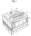
- FIGs 1-3 show a laser printer, in which the present invention is embodied.
- the printer comprises a printer housing 10 including a movable front cover 10a which can be moved from a closed position as shown in Fig. 1 to an open position as shown in Fig. 2.
- the printer housing 10 also includes a movable upper cover 10b which can be moved from a closed position as shown in Fig. 1 to an open position as shown in Fig. 3.
- the top surface of the upper cover 10b serves as a receptacle for printed paper.
- the upper cover 10b has a paper stopper 12 provided on the top surface thereof against which the leading edge of a printed sheet abuts when it is discharged from the printer.
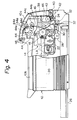
- Fig. 4 schematically shows a part of the interior arrangement of the printer shown in Figs. 1 to 3.
- the printer comprises a printing unit 14 for printing on a recording medium, such as a sheet of paper, provided in the housing 10.
- a recording medium such as a sheet of paper
- the printing unit 14 is removable from the housing 10, and thus maintenance of the printer can be easily carried out.
- the printing unit 14 comprises a rotary photosensitive drum 16 (a latent image carrying body) which is rotated in the direction indicated by the arrow in Fig. 6 during operation of the printer.
- the drum 16 may be an aluminum cylindrical hollow member with a photoconductive insulating film bonded to the cylindrical surface thereof.
- the photoconductive insulating film is made of an organic photoconductor (OPC).
- the printing unit 14 also comprises a conductive brush type charger 18, formed of a plurality of conductive filaments, which is rotated such that the free ends of the filaments are in contact with the photosensitive drum 16.
- the charger 18 is connected to an electric power source (not shown) so as to give a uniformly distributed electric charge to the photoconductive insulating film of the drum 16.
- the charged area of the drum 16 may have a potential of about -650 volts. As shown in Fig.
- the printer also comprises: a laser beam scanner 20 including a laser source, such as a semiconductor laser diode, for emitting a laser light; an optical system for focusing the laser light into a laser beam LB; and an optical scanning system, such as a polygon mirror, for deflecting the laser beam LB in the direction of the central axis of the drum 16, so that the charged area of the drum 16 is scanned by the laser beam LB.
- the laser beam LB is switched on and off on the basis of binary image data obtained from, for example, a word processor, computer or the like, so that an electrostatic latent image is written as a dot image on the charged area of the drum 16.
- the charges are released from the irradiated zone so that the latent image is formed as a potential difference between the irradiated zone and the remaining zone.
- the printing unit 14 further comprises a developing device 22 for electrostatically developing the latent image with a non-magnetic type developer composed of, for example, a polyester resin-based toner component, i.e., coloured fine polyester resin particles.
- the developing device 22 includes a vessel 22a for holding the developer or toner.
- a developing roller 22b is provided within the vessel 22a in such a manner that a portion of the developing roller 22b is exposed from the vessel 22a and pressed against the surface of the photosensitive drum 16 to establish a given nip width therebetween.
- the developing roller 22b is a conductive foam rubber roller, which may be formed of a conductive polyurethane foam rubber material, urethane foam rubber material, conductive silicone foam rubber material or the like, so that pore openings appear on the surface of the developing roller 22b.
- the developing roller 22b is rotated in the direction indicated by the arrow in Fig. 6.
- the toner particles are entrained and carried by the surface of the developing roller 22b to form a developer or toner layer therearound, and are brought to the surface of the drum 16 for development of the latent image formed thereon.
- the developing device 22 also includes a blade member 22c supported by the vessel 22a by attachment fittings, generally indicated by reference 22d, such that the blade member 22c engages the surface of the developing roller 22b.
- the blade member 22c makes uniform the thickness of the toner layer formed around the developing roller 22b, whereby even development of the latent image can be ensured.
- the blade member 22c may be formed of stainless steel having a thickness of about 0.1 mm, and is subjected to a voltage of about -400 volts, so that the toner particles are negatively charged by a charge-injection effect.
- the developing roller 22b is subjected to a developing bias voltage of -300 volts, and the negatively charged toner particles electrostatically adhere only to the latent image zone which has a potential of about -100 volts.
- the potential of the latent image zone is increased to -600 volts, as the latent image zone is charged by the negative particles.
- the developing device 22 further includes a toner-removing roller 22e rotatably provided within the vessel 22a and resiliently pressed against the developing roller 22b. Similar to the developing roller 22b, the toner-removing roller 22e is also a conductive foam rubber roller, which may be formed of a conductive polyurethane foam rubber material, urethane foam rubber material, conductive silicone foam rubber material or the like, so that pore openings appear on the surface of the toner-removing roller 22e. During operation of the printer, the toner-removing roller 22e is rotated in the same direction as the developing roller 22b, as indicated by the arrow in Fig. 6, so that, at the contact zone between the rollers, the surfaces thereof 22b and 22e rub against each other in reverse directions.
- the toner-removing roller 22e serves to feed toner particles to the developing roller 22b at one side of the nip therebetween (i.e., the left side in Fig. 6), because the toner particles entrained by the toner-removing roller 22e are moved towards the nip between the rollers 22b and 22e.
- the toner-removing roller 22e is negatively charged by being subjected to a voltage of about -400 volts, so that penetration of the toner particles thereinto is prevented.
- the vessel 22a may be provided with a paddle roller 22f and an agitator 22g rotated in the directions indicated by the respective arrows in Fig. 6.
- the paddle roller 22f serves to move the toner particles towards the toner-removing roller 22e, and the agitator 22g agitates the toner to stop it being caught on the edges of the vessel 22a.
- the developing device 22 may also be provided with a developer-supplying tank 22h detachably received therein and having a paddle blade 22i rotated in the direction indicated by the arrow in Fig. 6.
- the vessel 22a is in communication with the tank 22h through an opening 22j formed in a side wall of the vessel 22a and a port 22k in the tank 22h, as shown in Fig. 6.
- the printing unit 14 further includes a conductive roller type transfer charger 24 for electrostatically transferring the developed toner image from the photosensitive drum 16 to a sheet of paper.
- the transfer charger 24 may be formed of a conductive polyurethane foam rubber material, urethane foam rubber material, conductive silicone foam rubber material or the like, so that pore openings appear on the surface thereof.
- the transfer roller 24 is resiliently pressed against the drum 16, and is subjected to an application of electrical energy so that positive charges are supplied to the paper, whereby the negatively-charged toner image can be electrostatically attracted to the paper.
- the printer is provided with a detachable paper cassette 26 in which a stack of cut sheet paper is received.
- the paper cassette 26 has a paper feeding roller 28 incorporated therein.
- a paper guide 30 extends from the paper exit of the paper cassette 26 towards a nip between the drum 16 and the transfer roller 24, and has a pair of register rollers 32 associated therewith.
- papers to be printed are fed one by one from the stack of paper by driving the paper feeding roller 28.
- the fed paper is stopped once at the register roller 32, and is then introduced into the nip between the drum 16 and the transfer roller 24 through the paper guide 30 at a given timing, so that the developed toner image can be transferred to the paper by the transfer roller 24.
- the developed toner image cannot be completely transferred from the drum 16 to the paper. Namely, a part of the developed toner image is inevitably left as residual toner particles on the surface of the drum 16.
- the residual toner particles are removed from the drum surface by a scraper type blade 34 applied thereto (Fig. 6). The removed toner particles are received in a vessel 36.
- a sheet of paper can be manually introduced into the nip between the drum 16 and the transfer roller 24.
- the front cover 10a has a movable guide plate 38 associated therewith which is rotatable about a pivot pin 40.
- the guide plate 38 When the guide plate 38 is moved outwards from the vertical position shown in Fig. 4 to a horizontal position, the paper can be manually set on the horizontally-positioned guide plate 38 so that the leading edge thereof is abutted to a nip between a pair of paper feeding rollers 42.
- the paper feeding rollers 42 By driving the paper feeding rollers 42, the paper is fed to the nip between the drum 16 and the transfer roller 24.
- the fixing device 44 comprises a frame housing 44a supported by the movable front cover 10a, a heat roller 44b rotatably supported by the frame housing 44a, and a backup roller 44c rotatably supported by the frame housing 44a and engaged with the heat roller 44b to form a nip therebetween.
- the rollers 44b and 44c are rotated in the respective directions indicated by the arrows in Fig. 4 during operation of the printer.
- the paper carrying the transferred toner image is introduced into the nip between the rollers 44b and 44c through the paper guide 46. While the paper is passing through the nip, the toner image thereon is in direct contact with the heat roller 44b and thus is thermally fused and fixed on the paper.
- the paper carrying the fixed toner image is discharged from the frame housing 44a by a pair of paper guide rollers 44d provided therein and is then discharged from the printer through a pair of paper discharging rollers 46.
- the sheets of discharged paper are successively stacked on the top surface of the upper cover 10b.
- the toner fixing device 44 is provided with a cleaning roller 44e which is resiliently pressed against the heat roller 44b and is for removing the fused toner stain therefrom.
- the present invention is directed to the conductive foam rubber roller used as the developing roller 22b or the transfer roller 24.
- the conductive foam rubber roller can be produced by substantially the same processes as those known processes mentioned hereinbefore. Namely, a suitable resin material, such as polyurethane, silicone or the like, containing a conductive filler such as carbon black or a fine metal powder, and a water-soluble foam-providing substance, such as polyvinyl alcohol or methyl cellulose, is extruded as a long tubular product 48, as shown in Fig. 8. The extruded tubular product 48 is immersed in a body of water 50 held by a container 52, as shown in Fig.
- the water-soluble foam-providing substance dissolves in the water so that a foam structure is given to the tubular product 48.
- This tubular foam product is cut into tubular roller elements 54 having a predetermined length, as shown in Fig. 10.
- the amount of conductive filler is selected so that the tubular foam product 48 has the desired resistivity
- the amount of water-soluble foam-providing substance is selected so that the tubular foam product 48 has the desired density of cells.
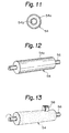
- Each tubular roller element 54 is covered at an outer wall surface thereof by a solid skin layer 54a, and an inner solid skin layer 54b is formed at an inner wall surface of a central bore of the tubular roller element 54, as shown in Fig. 11.
- the formation of these solid skin layers 54a and 54b is inevitable in the above-mentioned process for the production of the tubular roller element 54.
- the content of the conductive filler in the solid skin layers 54a and 54b is very small in comparison with that in the internal foam structure of the tubular roller element 54.
- the electrical resistivity of the solid skin layers 54a and 54b is considerably higher than that of the inner foam structure of the tubular roller element 54.
- the solid skin layers 54a and 54b have a thickness of from about 1 to about 5 ⁇ m which is variable along the longitudinal axis of the tubular roller element 54.
- the tubular roller element 54 is mounted and fixed on a metal shaft member 56 by using a suitable adhesive such as a thermosetting adhesive.
- a suitable adhesive such as a thermosetting adhesive.
- the solid skin layer 54a of the tubular roller element 54 is then removed by applying an abrasive stone 58 to the tubular roller element 54 while rotating the conductive foam rubber roller, whereby pore openings appear on the surface of the tubular roller element 54.
- a conductive foam rubber roller for use as the developing roller 22b, the toner-removing roller 22e, or the transfer roller 24 can be obtained.
- this conductive foam rubber roller cannot be put directly to use. This is because a sufficient electric contact between the tubular roller element 54 and the metal shaft member 56 cannot be ensured due to the existence of the solid skin layer 54b therebetween, which exhibits a high resistivity because of the lack of the conductive filler dispersed therein.
- the conductive foam rubber roller element 54 is subjected to an application of electrical energy, the supply of the electrical energy thereto is carried out through the metal shaft member 56.
- the electric contact establishing means comprises a disc-like contact member 60 formed of a suitable metal material such as copper.
- the contact member 60 has a central opening 60a formed therein, the diameter of which is slightly larger than that of the metal shaft member 56, and an integrally formed tongue element 60b, a free end of which slightly projects in the central opening 60a.
- the contact member 60 is inserted onto the metal shaft member 56 from one end thereof, as shown in Fig.
- the contact member 60 may be adhered to the end face of the tubular roller element 54 by thermally fusing the material of the foam structure of the tubular roller element 54 at the end face thereof to the contact member 60.
- a plurality of conductive foam rubber rollers were produced by the process mentioned above, and the amount of conductive filler was selected so that the foam structure of each conductive tubular roller element had a volume resistivity of 10 5 ⁇ cm. It was found that the volume resistivity of the produced conductive foam rubber rollers was in the range of from about 10 6 ⁇ cm to about 10 7 ⁇ cm.
- EP-A-0541375 discloses that an electric contact between the tubular roller element and the metal shaft member is established by a disc-like metal contact member being merely pressed against the end face of the tubular roller element.
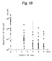
- EP-A-0541375 discloses another type of disc-like metal contact member, indicated by reference number 62 in Fig. 16. This contact member 62 is similar to the contact member 60, but it is provided with a pair of nail-like elements 64 diametrically formed therein. The nail elements 64 penetrate into the foam structure of the tubular roller element 54 when the metal disc-like member 62 is abutted against the end face thereof, as shown in Fig. 17.
- a plurality of conductive foam rubber rollers were produced in accordance with EP-A-0541375.
- the amount of conductive filler was selected so that the foam structure of each conductive tubular roller element had a volume resistivity of 10 5 ⁇ cm.
- the volume resistivity of the produced conductive foam rubber rollers was in a wider range than those of the first embodiment of the present invention.
- the volume resistivity of the conductive foam rubber rollers was in the range of from abcut 10 5 ⁇ cm to about 10 3 ⁇ cm.
- the volume resistivity of the conductive foam rubber rollers was in the range of from about 10 5 ⁇ cm to about 10 3 ⁇ cm.
- the volume resistivity of the conductive foam rubber rollers produced in accordance with the first embodiment of the present invention were in the narrower range of from about 10 6 ⁇ cm to about 10 5 ⁇ cm, as mentioned above.
- the adhesive area should be made as large as possible.
- the adhesive area S should at least satisfy the following formula: I/S ⁇ 0.1 where I indicates a current ( ⁇ A) flowing between the tubular roller element 54 and the metal shaft member 56.
- Figures 19 and 20 show another embodiment for establishing sufficient electric contact between the tubular roller element 54 and the metal shaft member 56.
- an electric heater element 68 is simultaneously extended through the central bore of the tubular roller element 54.
- the electric heater element 68 receives electrical energy from an electric source 70, and a part of the inner solid skin layer 54b of the tubular roller element 54 is thereby thermally fused and broken by the electrically-energized heater element 68.
- the electric heater element 68 is drawn out of the central bore of the tubular roller element 54, so that the metal shaft adheres directly to the internal foam structure of the tubular roller element 54 which has a larger amount of conductive filler.
- sufficient electric contact can be established between the tubular roller element 54 and the metal shaft member 56.
- the removal of the outer solid skin layer 54a of the tubular roller element 54 may be carried out either before or after the electric contact is established between the tubular roller element 54 and the metal shaft member 56.
- Figure 21 shows yet another embodiment for establishing sufficient electric contact between the tubular roller element 54 and the metal shaft member 56.
- a high voltage is applied between the tubular roller element 54 and the metal shaft member 56 to perform an electrical insulation-breakage of the inner solid skin layer 54b.
- a split type electrode 72 including two block members 72a and 72b hinged to each other is attached to the tubular roller element 54, as shown in Fig. 21.
- the metal shaft member 56 and the electrode 72 are then connected to a high voltage source 74.
- the inner solid skin layer 54b can be electrically broken by, for example, applying a voltage of 1 kV from the high voltage source 74 between the tubular roller element 54 and the metal shaft member 56.
- the inner solid skin layer 54b becomes locally fused due to a concentration of the electrical current at a location of the inner solid skin layer 54b having a relatively smaller resistivity.
- sufficient electric contact can be established between the tubular roller element 54 and the metal shaft member 56.
- the developing device 22 may use a non-magnetic type developer which includes a resin powder component as an additional component thereof.
- the resin powder has a polarity opposite to that of the toner component by a triboelectrification therebetween. Since the developer composed of the polyester resin-based toner component is negatively charged, as mentioned above, the resin powder component should be formed of melamine resin, acrylic resin, styrene acrylic resin or the-like which can be positively charged by the triboelectrification with the polyester resin-based toner component. This is shown in Fig. 22, in which the toner component and the resin powder component are indicated by T and P, respectively.
- the diameter of the toner component T is larger than that of the resin powder component P. For example, when the toner component has an average diameter of about 10 ⁇ m, the resin powder component may have a diameter of about 0.3 ⁇ m.
- the developer preferably includes 0.5 weight percent of the resin powder component.
- the developer includes a resin powder component
- the toner component cannot be sufficiently charged by only triboelectrification with the resin powder component. Accordingly, it is necessary to charge further the toner component of the developer by the charge-injection effect derived from the application of -400 volts to the blade member 22c, as mentioned above. If the developer is composed of only toner component, the charge of the toner component is partially released due to the electric field formed between the photosensitive drum 16 and the developing roller 22b, so that some of the toner particles in the toner component may have the reverse charge. The reversely-charged toner particles result in a photographic fog.
- the charged toner component enters into the electric field formed between the photosensitive drum 16 and the developing roller 22b, the release of a charge of the charged toner component can be prevented by the existence of the resin powder component in the developer which is reversely charged with respect to the polarity of the charged toner component. Accordingly, proper development of an electrostatic latent image can be ensured without a photographic fog.
- the developing device 22 includes a conductive foam rubber developing roller 22b having pore openings.
- the diameter of the pore openings may be from about two and half times to about four times the average diameter of the toner component, whereby proper and stable development of an electrostatic latent image can be maintained over a longer period of operation.
- the toner component T is also electrostatically held through the intermediary of the reversely-charged resin powder component P.
- the diameter of the pore opening of the developing roller 22b is less than two and half times the average diameter of the toner component T, the developing roller 22b deteriorates prematurely due to the developer blocking the pore openings.
- conductive foam rubber developing rollers having pore opening diameters of 10, 20, 25, 40 and 50 ⁇ m, respectively, were produced.
- Each of the developing rollers were incorporated into the developing device 22 of the printer as shown in Figs. 1 to 7.
- 30,000 sheets of paper were solidly printed continuously using a developer composed of a polyester resin-based toner component having an average diameter of about 10 ⁇ m, and a melamine resin powder component (0.5 weight percent) having an average diameter of about 0.3 ⁇ m.
- the ratio of developing density of the last sheet to that of the initial sheet was evaluated. The results are shown in the graph of Fig.
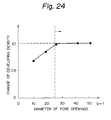
- the printer shown in Figs. 1 to 7 was operated in a non-solid printing manner with each of the developing rollers incorporated into the developing device 22 thereof.
- a developer composed of a polyester resin-based toner component having an average diameter of about 10 ⁇ m, and a melamine resin powder component (0.5 weight percent) having an average diameter of about 0.3 ⁇ m was used, and the optical density of a photographic fog occurring on the photosensitive drum 16 was measured.
- the printer was operated in a non-solid printing manner using a developer composed only of a polyester resin-based toner component having an average diameter of about 10 ⁇ m. The results are shown in the graph of Fig.
- the developing roller when the developer composed of the toner component and the resin powder component was used, the developing roller must have a pore opening diameter of less than 40 ⁇ m before the optical density of the photographic fog can be suppressed to less than 0.02 OD (optical density).
- the pore opening diameter exceeds 40 ⁇ m the optical density of the photographic fog increases abruptly. This proves that the mechanical capture of the toner component in the pore openings of the developing roller is weakened.
- the developing roller when the developer composed of only the toner component was used, the developing roller must have a pore opening diameter of less than 20 ⁇ m before the optical density of the photographic fog can be suppressed to less than 0.02 OD.
- the pore opening diameter exceeds 20 ⁇ m the optical density of the photographic fog increases abruptly. This proves that the hold of the toner component in the pore openings of the developing roller relies only on a mechanical force.
- the volume resistivity of the conductive foam rubber developing roller 22b should be in the range of from 10 4 ⁇ cm to 10 10 ⁇ cm.
- a high electrical current or an electrical discharge may easily occur between the developing roller 22b and the blade member 22c due to the potential difference (100 volts) therebetween.
- the occurrence of an electrical discharge generates heat, fusing not only the developer but also the developing roller.
- the volume resistivity of the developing roller 22b is more than 10 10 ⁇ cm, the absolute value of the potential of the developing roller 22b is gradually increased, causing a photographic fog.
- the size of the pore openings of the developing roller 22b and the value of the volume resistivity thereof can be easily controlled in the above-mentioned process for producing the conductive foam rubber roller.
- a non-magnetic type developer inclusive of a resin powder component contributes to the transferring process in which the developed toner image is transferred from the photosensitive drum 16 to a sheet of paper.
- the developed toner image is stuck against the surface of the drum 16 due to the Van der Waals attraction.
- the Van der Waals attraction acting between the developed toner image and the drum surface can be weakened because of the resin powder component.
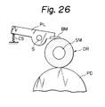
- Figure 26 shows a conventional arrangement including a conductive foam rubber developing roller DR resiliently pressed against a photosensitive drum PD.
- a plate-like lever PL is disposed adjacent the developing roller DR and is rotatably mounted on a shaft S.
- a metal blade member BM is fixed to one arm of the plate-like lever PL, and the other arm thereof is resiliently biased by a coil spring CS so that the metal blade member BM is resiliently pressed against the developing roller DR. Accordingly, the thickness of the layer of developer entrained by the developing roller DR should be uniformly regulated by the blade member BM. Nevertheless, one developer thickness cannot be made uniform for the reason discussed below:
- the shaft member SM of the developing roller DR is supported at the ends thereof, and thus may be resiliently deformed or bent at a very small angle when the blade member BM is pressed against the developing roller at a given pressure for the regulation of the developer thickness. Therefore, the developing roller DR cannot be subjected to a uniform distribution of pressure by the blade member BM. As represented by a plurality of arrows in Fig. 27, the pressure exerted on the central zone of the developing roller DR is smaller than that exerted on the end zones thereof.
- the end portions of the blade member BM are pressed deeply into the developing roller DR, but the central portion of the blade member BM is not pressed deeply into the developing roller DR, as represented by a hatching zone in Fig. 27.
- the thickness of the developer regulated by the blade member BM which is represented by a hatching zone in Fig. 28, cannot be made uniform by the blade member BM.
- the developing device 22 is constituted such that the regulation of the developer thickness can be made uniform by the blade member 22c as much as possible.
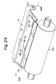
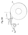
- the developing device 22 includes a plate-like lever member 76, shown in Figs. 29 and 30, which is rotatably mounted on a shaft 78 which is supported by the side walls of the developer vessel 22a.
- the blade member 22c is held between a fitting plate 80 and an arm portion of the plate-like lever member 76, and is securely attached thereto by screws 82.
- the other arm portion of the plate-like lever member 76 is resiliently biased by a pair of leaf springs 84 (Fig. 30), so that the blade member 22c is resiliently pressed against the developing roller 22b.
- the developing roller 22b has a diameter of 20 mm, and the shaft member 22b' has a diameter of 12 mm.
- the developing roller 22b also has an effective printing width of 300 mm, and a conductive foam rubber roller element formed of a foam polyurethane material.
- the blade member 22c is formed of a stainless steel sheet having a thickness of 0.1 mm.
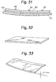
- the plate-like lever member 76 is curved, as exaggeratedly shown in Fig. 31.
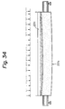
- the lever member 76 is obtained from a flat plate (as shown in Fig. 32) by pressing it into a shape (as shown in Fig. 33).
- the degree of curvature of the lever member 76 is about 0.1 mm, as shown in Fig. 33. Accordingly, when the blade member 22c is securely held between the fitting plate 80 and the arm portion of the plate-like lever member 76 by the screws 82, it has the same curvature as the lever member 76. As is apparent from Figs. 29 to 31, the convex side of the curved blade member 22c is tangentially pressed against the developing roller 22b.
- the blade member 22c extends from the fitting plate 80 by about 1.5 mm, and is pressed against the developing roller 22b by the pair of leaf springs 84 at a linear pressure of from 25 to 50 g/cm.
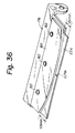
- the pressure exerted on the central zone of the developing roller 22b becomes larger than that exerted on the end zones thereof. Accordingly, the blade member 22c can be uniformly pushed into the developing roller 22b, as represented by the hatching zone in Fig. 34, and thus the developing roller 22b can be subjected to a uniform distribution of pressure by the blade member 22c, as represented by a plurality of arrows in Fig. 34.
- the solid line represents the thickness of the developer regulated by the blade member 22c
- the broken line represents the thickness of the developer regulated by the blade member BM shown in Fig. 26. It is apparent from this graph that the developer thickness can be made more uniform by the curved blade member 22c.
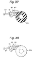
- FIGs 36 to 38 show another embodiment of the present invention.
- the blade member 22c is securely held between the fitting plate 80 and the arm portion of the plate-like lever member 76 by the screws 82, and the other arm portion of the plate-like lever member 76 is resiliently biased by the leaf springs 84 (Figs. 37 and 38), so that the blade member 22c is resiliently pressed against the developing roller 22b.
- the blade member 22c is kept flat between the fitting plate 80 and the arm portion of the plate-like lever member 76.
- the fitting plate 80 has a convex profile such that the length of the portion of the blade member 22c which extends from the fitting plate 80 varies in accordance with the convex profile.
- the blade member 22c extends from the fitting plate 80 by about 0.7 mm at the centre thereof, and by 1.5 mm at the ends thereof, as shown in Fig. 36. Furthermore, the developing roller 22b and the blade member 22c have the same particulars as mentioned above. The blade member 22c is pushed more deeply into the developing roller 22b at the centre thereof, as shown in Fig. 37, and is not pushed deeply into the developing roller 22b at the ends thereof. The thickness of the developer regulated by the flat blade member 22c exhibits substantially the same characteristics as shown by the solid line in the Fig. 35.
- Figure 39 shows yet another embodiment of the present invention.
- the developing device 22 which otherwise has the same particulars as mentioned above includes a plate-like lever member 76' which is rotatably supported by the side walls of the developer vessel 22a and is resiliently biased by the leaf springs 84 so that the blade member 22c is resiliently pressed against the developing roller 22b.
- the blade member 22c is securely attached to a tongue-like member 86 projecting from the centre of the lever member 76'.
- the blade member 22c is formed of a cold-rolled steel having a thickness of 3 mm, and may have a width of from 3.5 to 4.0 mm.
- a pressure of 1.8 kg is exerted on the developing roller 22b by the leaf springs 84 through the tongue-like member 86 and the blade member 22c.
- the thickness of the developer regulated by the blade member 22c has the characteristics shown by the solid line in a graph of Fig. 40. Note, in this graph, the broken line represents the thickness of the developer regulated by the blade member BM shown in Fig. 26.
Description
- The present invention generally relates to a conductive rubber roller for use in an image formation apparatus in which an electrostatic latent image formed on an image carrying body, such as a photosensitive body, a dielectric body or the like, is electrostatically developed with a developer or toner, and the developed image is transferred from the image carrying body to a recording medium, such as a sheet of paper. The conductive rubber roller may be used in the developing process and/or the transferring process in the image formation apparatus.
- The well-known electrophotographic recording apparatus is an example of the image formation apparatus mentioned above. In this apparatus, the following processes are typically carried out:
- a) a uniform distribution of electrical charges is produced on the surface of an electrostatic latent image carrying body;
- b) an electrostatic latent image is formed on the charged area of the body by an optical writing means, such as a laser beam scanner, an LED (light emitting diode) array, a liquid crystal shutter array or the like;
- c) the latent image is developed as a visible image by a developer or toner, which is electrically charged to become electrostatically adhered to the latent image zone;
- d) the developed and charged toner image is electrostatically transferred from the body to a recording medium, such as a sheet of paper; and
- e) the transferred toner image is fixed and recorded on the paper.
-
- Typically, the electrostatic latent image carrying body is an electrophotographic photoreceptor, usually formed as a drum, called a photosensitive drum. The drum has a cylindrical conductive substrate formed of a metal such as aluminum and, bonded to the surface thereof, a photoconductive insulating film formed of an organic photoconductor (OPC), a selenium photoconductor or the like.
- A non-magnetic developer is well known as one type of developer used in the developing process. The developer is composed of only a toner component, i.e., coloured fine resin particles. A developing device using the non-magnetic type developer includes a vessel for holding the developer. A conductive solid rubber roller is provided within the vessel as a developing roller in such a manner that a portion of the solid rubber roller is exposed therefrom and is pressed against the photosensitive drum. When the conductive rubber roller is rotated within the vessel, the toner component is frictionally entrained by the surface of the rubber roller to form a developer layer therearound and the toner component can thereby be brought to the photosensitive drum for development of the electrostatic latent image formed thereon. The developing device further includes a blade member which is engaged with the surface of the developing roller to uniformly regulate the thickness of the developer layer formed therearound, so that even development of the latent image can be carried out. The blade member also serves to electrically charge the toner component by triboelectrification therebetween. In this developing device, development is carried out in such a manner that, in the area of contact between the photosensitive drum and the rubber roller with the developer layer, the charged toner component is electrostatically attracted and adhered to the latent image due to a bias voltage applied to the rubber roller.
- In the above-mentioned developing device using a non-magnetic type developer, the coefficient of friction of the surface of the rubber roller can be changed by environmental factors, especially, temperature and moisture content. If the coefficient of friction falls, the rubber roller cannot entrain a sufficient amount of the toner component necessary for development of the latent image.
- The Examined Japanese Utility Model Publication (Kokoku) No. 60-6846 discloses a solid rubber developing roller which has a rough surface by which the toner particles can be sufficiently entrained even when the coefficient of friction of the roller becomes small. Nevertheless, when the coefficient of friction increases due to a rise in temperature and moisture content, the toner component entrained by the rough surface of the rubber roller may be eliminated therefrom by the blade member due to an increase in the frictional coefficient of the toner component.
- US-A-5,076,201 discloses a developing roller for a non-magnetic type developer which is formed of a conductive open-cell foam rubber material so that pore openings appear on the surface of the developing roller. This open-cell foam rubber developing roller is softer than a solid rubber roller. Thus the toner component entrained by the rough surface of the rubber roller cannot be eliminated therefrom by the blade member, although the frictional coefficient of the toner component increases due to the rise in temperature and moisture content.
- In the transferring process in which the developed toner image is electrostatically transferred to a recording medium such as a sheet of paper, a conductive foam rubber roller is also used as an electric charging roller. The conductive foam rubber roller is resiliently pressed against the photosensitive drum, and is connected to a suitable electric source so as to give the sheet of paper an electric charge which has a polarity opposite to that of the developed toner image. In this way, the developed toner image can be electrostatically transferred to the sheet of paper during the passage of the sheet of paper through the nip between the photosensitive drum and the charging roller.
- It is preferable to use a conductive foam rubber roller as the developing roller and the charging roller. This is because this type of roller is relatively soft and so the operating life of the photosensitive drum can be extended as long as possible, i.e., the harder the developing and charging rollers, the greater the wear of the photoconductive insulating film of the drum.
- Conventionally, a conductive foam rubber roller may be produced by the following process:
- a) a suitable resin material, e.g., polyurethane, urethane, silicone, or the like, containing a conductive filler, such as carbon black or a fine metal powder, and a water-soluble foam-providing substance, such as polyvinyl alcohol or methyl cellulose, is extruded as a long tubular product;
- b) the extruded tubular product is immersed in water, so that the water-soluble foam-providing substance dissolves in the water and the tubular product has a foam structure;
- c) the tubular foam product is cut into tubular roller elements having a predetermined length; and
- d) the tubular roller element is mounted and fixed on a metal shaft member using a suitable adhesive, such as a thermosetting adhesive, thereby to produce a conductive foam rubber roller.
-
- This conductive foam rubber roller must be further treated before it can be used as a developing roller or a charging roller. This is because the centre surface of the tubular roller element is covered by a solid skin layer which has a thickness of about 1 to 5µm and in which the content of the conductive filler is very small in comparison with that of the internal foam structure of the tubular element. Thus, the conductive foam rubber roller is finished by removing the solid skin layer.
- Nevertheless, many of the known finished conductive foam rubber rollers cannot have a desired electric characteristic when electrical energy is applied to the tubular roller element through the metal shaft member. This is due to the existence of an inner solid skin layer formed on the inner wall surface of the central bore of the tubular roller element. In particular, the electric resistivity of the inner solid skin layer is considerably higher than that of the foam structure of the tubular roller element because the content of the conductive filler therein is also very small, and because the thickness of the inner solid skin layer varies along the longitudinal axis of the metal shaft member. Thus, the electrical potential of the tubular roller element, which is obtained by application of electrical energy to the tubular roller element through the metal shaft member, is also variable along the longitudinal axis of the metal shaft member. Accordingly, when such a conductive foam rubber roller is used as a developing roller, for example, it is impossible to obtain even development of the latent image.
- Also, US-A-5,076,201 discloses that the pore openings of the conductive foam rubber developing roller should be at most twice the average diameter of the toner component to prevent penetration of the toner component into the pore openings. This conductive foam rubber developing roller cannot endure a recording operation in which the number of recorded sheets exceeds, for example, 30,000, because the pore openings thereof become completely blocked due to penetration of the toner component. Accordingly, the conductive foam rubber developing roller must be frequently replaced by a new one, in order for proper development of the electrostatic latent image to be maintained.
- US-A-5,076,201 further discloses that the blade member for uniformly regulating the thickness of the developer layer formed around the developing roller is formed of a conductive material such as metal, and that it is subjected to electrical energy to electrically charge the toner component at a given polarity by the charge-injection effect during regulation of the developer thickness. Nevertheless, a small part of the charged toner component may be reversely charged for the reason stated hereinafter in detail. Of course, the reversely-charged toner component results in a photographic fog.
- On the other hand, there is a tendency towards miniaturization of the image formation apparatus, especially when it is constructed for personal use. Accordingly, the developing device must also be miniaturized in proportion to the miniaturization of the image formation apparatus. Thus, the shaft member of the conductive foam rubber developing roller must be made slender. However, when the blade member is pressed against the developing roller at a given pressure for regulating a thickness of the developer entrained thereby, the slender shaft member becomes resiliently deformed or bent at a very small degree and the blade member cannot subject the developing roller to a uniform distribution of pressure. The pressure exerted on the central zone of the developing roller is smaller than that exerted on the end zones thereof, and thus the regulation of the developer thickness by the blade member cannot be uniform. Of course, a nonuniform developer layer results in uneven development of the electric latent image.
- Therefore, an object of the present invention is to provide an improved conductive foam rubber roller for use in an image formation apparatus as mentioned above, which roller comprises a conductive tubular foam rubber roller element having a central bore defined by a solid skin layer having an electric resistivity considerably higher than that of a conductive foam structure of the conductive tubular foam rubber element, and a conductive shaft member on which the conductive foam rubber roller element is mounted and fixed, wherein the conductive foam rubber roller has a desired electrical characteristic when electrical energy is applied to the tubular roller element through the metal shaft member, regardless of the existence of the solid skin layer.
- In accordance with a first aspect of the present invention, there is provided a conductive rubber roller for use in an image formation apparatus in which an electrostatic latent image formed on an image carrying body is electrostatically developed with a developer to form a developed image which is electrostatically transferred from the image carrying body to a recording medium, which conductive rubber roller comprises:
- a conductive tubular rubber roller element having an outer thicker portion which includes a predetermined amount of conductive filler dispersed therein, and an inner skin layer which defines a central bore of the roller element and exhibits an electrical resistivity higher than that of the outer thicker portion because of a lack of conductive filler; and
- a conductive shaft member fixed in the central bore of the conductive tubular rubber roller element, characterised by electrical contact establishing means provided between the outer thicker portion of the conductive tubular rubber roller element and the conductive shaft member for establishing electrical contact therebetween, said electrical contact establishing means comprising either
- (a) two conductive plate members mounted on the conductive shaft member, each adhered to a respective end face of the conductive tubular rubber roller element by a conductive adhesive,
- or (b) two conductive plate members mounted on the conductive shaft member, each adhered to a respective end face of the conductive tubular rubber roller element by thermally fusing the material of the outer thicker portion at the end faces thereof with the conductive plate members,
- or (c) a break in the inner skin layer caused by an at least partial thermal fusing of the inner skin layer,
- or (d) a break in the inner skin layer caused by electrical insulation-breakage of the inner skin layer.
-
- In accordance with a second aspect of the present invention, there is provided an electrophotographic recording apparatus, comprising:
- an electrostatic latent image carrying body means;
- a developing roller for carrying an electrostatically-charged developer to the electrostatic latent image carrying body means for the developer to develop an electrostatic latent image carried on the electrostatic latent image carrying body means thereby to form a developed image; and
- a transfer roller for electrostatically transferring the developed image from the electrostatic latent image carrying body means to a recording medium,
- wherein at least one of the developing roller and the transfer roller is a conductive rubber roller in accordance with the first aspect of the invention.
-
- The developing roller may be resiliently pressed against the latent image carrying body means and be formed of an open-cell foam rubber material so that pore openings appear on the surface thereof to entrain and carry the developer to the surface of the latent image carrying body means, the apparatus further comprising a developer regulating means engaged with the developing roller to regulate the thickness of the developer entrained and carried thereby.
- The developer may be composed of a toner component and a resin powder component, one component of which has a polarity opposite to that of an electric charge of the other component by triboelectrification therebetween. When the developer regulating means is formed of a conductive material, such as metal, in use it is supplied with electrical energy electrically to charge the toner component of the developer at a given polarity by a charge-injection effect during regulation of the thickness of the developer. Also, preferably, the pore openings of the developing roller have a diameter of from about two and a half to about four times the average diameter of the toner component of the developer. The toner component of the developer may be a polyester resin-based toner component, and the resin powder component may be formed of a resin material selected from melamine resin, acrylic resin, and styrene acrylic resin. Preferably, the conductive open-cell foam rubber material of the developing roller has a volume resistivity of from about 104 Ω·cm to about 1010 Ω·cm. The developing roller may be formed of a conductive open-cell foam rubber material selected from conductive open-cell foam polyurethane rubber material, a conductive open-cell foam urethane rubber material, and a conductive open-cell foam silicone rubber material.
- The developer regulating means may comprise a thin metal blade member pressed against the developing roller, and compensating means for compensating for resilient deformation of the shaft member of the developing roller caused when the thin metal blade member is pressed against the developing roller. The compensating means may comprise a curvature of the thin metal blade member, which curvature is defined such that the developer carrying roller means can be subjected to a uniform distribution of pressure by the thin metal blade member to make the thickness of the developer uniform. The developer regulating means may further comprise a fitting plate member for rigidly supporting a part of the thin metal blade member. In this case, the compensating means comprises a convex profile of the fitting plate member which is defined such that the developing roller can be subjected to a uniform distribution of pressure by the thin metal blade member. Alternatively, the compensating means may comprise means for applying pressure to the centre of the thin metal blade member, which pressure is controlled such that the developing roller can be subjected to a uniform distribution of pressure by the thin metal blade member.
- For a better understanding of the invention, and to show how the same may be carried into effect, reference will now be made, by way of example only, to the accompanying drawings, in which:-
- Figure 1 is a perspective view of an electrophotographic laser printer in accordance with one embodiment of the present invention;
- Figure 2 is a perspective view of the laser printer of Fig. 1, showing the front cover open;
- Figure 3 is a perspective view of the laser printer of Fig. 1, showing the upper cover further open;
- Figure 4 is a partially cutaway side view of the laser printer of Fig. 1, schematically illustrating a main part of an interior arrangement thereof;
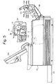
- Figure 5 is a side view of the laser printer of Fig. 1, showing the front and upper covers opened to remove a printing unit therefrom;
- Figure 6 is an enlarged sectional side view of the printing unit of Fig. 5;
- Figure 7 is a partially cutaway side view of the laser printer of Fig. 1, showing the front and upper covers opened for exchange of a toner tank;
- Figure 8 is a perspective view showing an extruded long tubular product formed of a resin material containing a conductive substance and a water-soluble foam-providing substance;
- Figure 9 is a schematic view showing a container holding a body of water in which the tubular product of Fig. 8 is immersed so that the water-soluble foam-providing substance dissolves in the body of water to produce a tubular foam product;
- Figure 10 is a perspective view showing tubular roller elements cut from the tubular foam product of Fig. 9;
- Figure 11 is an end view of the tubular roller element of Fig. 10;
- Figure 12 is a perspective view showing a conductive foam rubber roller produced by mounting the tubular roller element of Fig. 11 on a metal shaft member;
- Figure 13 is a perspective view showing removal of the outer solid skin layer of the conductive foam rubber roller of Fig. 12 by application of an abrasive stone;
- Figure 14 is a perspective view showing the production of a conductive foam rubber roller in accordance with the present invention;
- Figure 15 is a partial side view showing the conductive foam rubber roller obtained according to Fig. 14;
- Figure 16 is a partial perspective view showing the production of a conductive foam rubber roller not in accordance with the present invention;
- Figure 17 is a partial longitudinal-sectional view showing the conductive foam rubber roller obtained according to Fig. 16;
- Figure 18 is a graph showing a distribution of volume resistivity of conductive foam rubber rollers obtained according to Fig. 16;
- Figure 19 is a longitudinal-sectional view showing the production of another conductive foam rubber roller in accordance with the present invention;
- Figure 20 is an end view of the conductive foam rubber roller of Fig. 19;
- Figure 21 is a perspective view showing the production of yet another conductive foam rubber roller in accordance with the present invention;
- Figure 22 is a schematic view of a non-magnetic type developer composed of a toner component and a resin powder component, one component of which has a polarity opposite to that of the other component by triboelectrification therebetween;
- Figure 23 is a schematic view showing the non-magnetic type developer of Fig. 23 captured in a pore opening of a conductive foam rubber developing roller;
- Figure 24 is a graph showing the ratio of developing density of the last sheet to that of the first sheet when 30,000 sheets of paper are solid printed by the printer of Figs. 1-7 into which is incorporated developing rollers having pore opening diameters of 10, 20, 25, 40, and 50µm, respectively;
- Figure 25 is a graph showing an optical density of a photographic fog which occurs when operating, in a non-solid printing manner, the printer of Figs. 1 to 7 incorporating developing rollers having pore opening diameters of 10, 20, 25, 40, and 50µm, respectively;
- Figure 26 shows a conventional arrangement including a conductive foam rubber developing roller resiliently pressed against a photosensitive drum, and a metal blade member resiliently pressed against the developing roller for regulating the thickness of the developer entrained thereby;
- Figure 27 is a schematic view showing the conductive foam rubber developing roller of Fig. 26 together with a distribution of pressure exerted on the developing roller by a blade member;
- Figure 28 is a partial side view showing the conductive foam rubber developing roller together with a developer entrained thereby and regulated by the blade member shown in Figs. 26 and 27;
- Figure 29 is a perspective view of a partial arrangement of a developing device in accordance with the present invention;
- Figure 30 is an end view of the arrangement of Fig. 29;
- Figure 31 is a cross-sectional view taken along XXXI-XXXI line of Fig. 29;
- Figure 32 is a perspective view showing a flat plate used for producing a plate-like lever member of the arrangement of Figs. 29 and 30;
- Figure 33 is a perspective view showing the shape obtained by pressing the flat plate of Fig. 32;
- Figure 34 is a side view showing a conductive foam rubber developing roller of the arrangement shown in Figs. 29 and 30 together with the distribution of pressure exerted on the developing roller by the curved blade member of said arrangement;
- Figure 35 is a graph showing the thickness of the developer regulated by the curved blade member of the arrangement of Figs. 29 and 30;
- Figure 36 is a perspective view of a partial arrangement of another type of developing device in accordance with the present invention;
- Figure 37 is an end view showing the arrangement of Fig. 36, in which a conductive foam rubber developing roller is shown in cross-section;
- Figure 38 is an end view similar to Fig. 37, showing the conductive foam rubber developing roller in end view;
- Figure 39 is a perspective view of a partial arrangement of yet another type of developing device in accordance with the present invention; and
- Figure 40 is a graph showing the thickness of the developer regulated by the blade member of the arrangement of Fig. 39.
-
- As an example of an electrophotographic recording apparatus, Figures 1-3 show a laser printer, in which the present invention is embodied. The printer comprises a
printer housing 10 including a movablefront cover 10a which can be moved from a closed position as shown in Fig. 1 to an open position as shown in Fig. 2. Theprinter housing 10 also includes a movableupper cover 10b which can be moved from a closed position as shown in Fig. 1 to an open position as shown in Fig. 3. The top surface of theupper cover 10b serves as a receptacle for printed paper. To this end, theupper cover 10b has apaper stopper 12 provided on the top surface thereof against which the leading edge of a printed sheet abuts when it is discharged from the printer. - Fig. 4 schematically shows a part of the interior arrangement of the printer shown in Figs. 1 to 3. The printer comprises a
printing unit 14 for printing on a recording medium, such as a sheet of paper, provided in thehousing 10. As shown in Fig. 5, when the front andupper covers printing unit 14 is removable from thehousing 10, and thus maintenance of the printer can be easily carried out. - As best shown in Fig. 6, the
printing unit 14 comprises a rotary photosensitive drum 16 (a latent image carrying body) which is rotated in the direction indicated by the arrow in Fig. 6 during operation of the printer. Thedrum 16 may be an aluminum cylindrical hollow member with a photoconductive insulating film bonded to the cylindrical surface thereof. In this embodiment, the photoconductive insulating film is made of an organic photoconductor (OPC). - The
printing unit 14 also comprises a conductivebrush type charger 18, formed of a plurality of conductive filaments, which is rotated such that the free ends of the filaments are in contact with thephotosensitive drum 16. Thecharger 18 is connected to an electric power source (not shown) so as to give a uniformly distributed electric charge to the photoconductive insulating film of thedrum 16. For example, the charged area of thedrum 16 may have a potential of about -650 volts. As shown in Fig. 4, the printer also comprises: alaser beam scanner 20 including a laser source, such as a semiconductor laser diode, for emitting a laser light; an optical system for focusing the laser light into a laser beam LB; and an optical scanning system, such as a polygon mirror, for deflecting the laser beam LB in the direction of the central axis of thedrum 16, so that the charged area of thedrum 16 is scanned by the laser beam LB. During scanning, the laser beam LB is switched on and off on the basis of binary image data obtained from, for example, a word processor, computer or the like, so that an electrostatic latent image is written as a dot image on the charged area of thedrum 16. In particular, when a zone of the charged area is irradiated by the laser beam LB, the charges are released from the irradiated zone so that the latent image is formed as a potential difference between the irradiated zone and the remaining zone. - The
printing unit 14 further comprises a developingdevice 22 for electrostatically developing the latent image with a non-magnetic type developer composed of, for example, a polyester resin-based toner component, i.e., coloured fine polyester resin particles. The developingdevice 22 includes a vessel 22a for holding the developer or toner. A developingroller 22b is provided within the vessel 22a in such a manner that a portion of the developingroller 22b is exposed from the vessel 22a and pressed against the surface of thephotosensitive drum 16 to establish a given nip width therebetween. The developingroller 22b is a conductive foam rubber roller, which may be formed of a conductive polyurethane foam rubber material, urethane foam rubber material, conductive silicone foam rubber material or the like, so that pore openings appear on the surface of the developingroller 22b. During operation of the printer, the developingroller 22b is rotated in the direction indicated by the arrow in Fig. 6. Thus the toner particles are entrained and carried by the surface of the developingroller 22b to form a developer or toner layer therearound, and are brought to the surface of thedrum 16 for development of the latent image formed thereon. - The developing
device 22 also includes ablade member 22c supported by the vessel 22a by attachment fittings, generally indicated byreference 22d, such that theblade member 22c engages the surface of the developingroller 22b. Thus, theblade member 22c makes uniform the thickness of the toner layer formed around the developingroller 22b, whereby even development of the latent image can be ensured. Theblade member 22c may be formed of stainless steel having a thickness of about 0.1 mm, and is subjected to a voltage of about -400 volts, so that the toner particles are negatively charged by a charge-injection effect. During the developing process, the developingroller 22b is subjected to a developing bias voltage of -300 volts, and the negatively charged toner particles electrostatically adhere only to the latent image zone which has a potential of about -100 volts. The potential of the latent image zone is increased to -600 volts, as the latent image zone is charged by the negative particles. - The developing
device 22 further includes a toner-removingroller 22e rotatably provided within the vessel 22a and resiliently pressed against the developingroller 22b. Similar to the developingroller 22b, the toner-removingroller 22e is also a conductive foam rubber roller, which may be formed of a conductive polyurethane foam rubber material, urethane foam rubber material, conductive silicone foam rubber material or the like, so that pore openings appear on the surface of the toner-removingroller 22e. During operation of the printer, the toner-removingroller 22e is rotated in the same direction as the developingroller 22b, as indicated by the arrow in Fig. 6, so that, at the contact zone between the rollers, the surfaces thereof 22b and 22e rub against each other in reverse directions. Thus, residual toner particles not used for the development of the latent image are mechanically removed from the developingroller 22b. On the other hand, the toner-removingroller 22e serves to feed toner particles to the developingroller 22b at one side of the nip therebetween (i.e., the left side in Fig. 6), because the toner particles entrained by the toner-removingroller 22e are moved towards the nip between therollers roller 22e is negatively charged by being subjected to a voltage of about -400 volts, so that penetration of the toner particles thereinto is prevented. - The vessel 22a may be provided with a
paddle roller 22f and anagitator 22g rotated in the directions indicated by the respective arrows in Fig. 6. Thepaddle roller 22f serves to move the toner particles towards the toner-removingroller 22e, and theagitator 22g agitates the toner to stop it being caught on the edges of the vessel 22a. The developingdevice 22 may also be provided with a developer-supplyingtank 22h detachably received therein and having a paddle blade 22i rotated in the direction indicated by the arrow in Fig. 6. The vessel 22a is in communication with thetank 22h through anopening 22j formed in a side wall of the vessel 22a and aport 22k in thetank 22h, as shown in Fig. 6. When a predetermined amount of developer is consumed from the vessel 22a, rotation of the paddle blade 22i is carried out, whereby the developer is fed from thetank 22h to the vessel 22a. When thetank 22h becomes empty, it is exchanged for a new one, as shown in Fig. 7. - The
printing unit 14 further includes a conductive rollertype transfer charger 24 for electrostatically transferring the developed toner image from thephotosensitive drum 16 to a sheet of paper. Thetransfer charger 24 may be formed of a conductive polyurethane foam rubber material, urethane foam rubber material, conductive silicone foam rubber material or the like, so that pore openings appear on the surface thereof. Thetransfer roller 24 is resiliently pressed against thedrum 16, and is subjected to an application of electrical energy so that positive charges are supplied to the paper, whereby the negatively-charged toner image can be electrostatically attracted to the paper. - As shown in Fig. 4, the printer is provided with a
detachable paper cassette 26 in which a stack of cut sheet paper is received. Thepaper cassette 26 has apaper feeding roller 28 incorporated therein. Apaper guide 30 extends from the paper exit of thepaper cassette 26 towards a nip between thedrum 16 and thetransfer roller 24, and has a pair ofregister rollers 32 associated therewith. During the printing operation, papers to be printed are fed one by one from the stack of paper by driving thepaper feeding roller 28. The fed paper is stopped once at theregister roller 32, and is then introduced into the nip between thedrum 16 and thetransfer roller 24 through thepaper guide 30 at a given timing, so that the developed toner image can be transferred to the paper by thetransfer roller 24. - In the toner image transferring process, the developed toner image cannot be completely transferred from the
drum 16 to the paper. Namely, a part of the developed toner image is inevitably left as residual toner particles on the surface of thedrum 16. The residual toner particles are removed from the drum surface by ascraper type blade 34 applied thereto (Fig. 6). The removed toner particles are received in avessel 36. - In the illustrated printer, a sheet of paper can be manually introduced into the nip between the
drum 16 and thetransfer roller 24. To this end, thefront cover 10a has amovable guide plate 38 associated therewith which is rotatable about apivot pin 40. When theguide plate 38 is moved outwards from the vertical position shown in Fig. 4 to a horizontal position, the paper can be manually set on the horizontally-positionedguide plate 38 so that the leading edge thereof is abutted to a nip between a pair ofpaper feeding rollers 42. By driving thepaper feeding rollers 42, the paper is fed to the nip between thedrum 16 and thetransfer roller 24. - The paper discharged from the nip between the
drum 16 and thetransfer roller 24, i.e., the paper carrying the transferred toner image, is then moved along apaper guide 46 extending between thetransfer roller 24 and the fixingdevice 44 towards a tonerimage fixing device 44 for thermally fusing and fixing the transferred toner image on the paper. As shown in Figs. 4 and 5, the fixingdevice 44 comprises a frame housing 44a supported by the movablefront cover 10a, aheat roller 44b rotatably supported by the frame housing 44a, and abackup roller 44c rotatably supported by the frame housing 44a and engaged with theheat roller 44b to form a nip therebetween. Therollers - The paper carrying the transferred toner image is introduced into the nip between the
rollers paper guide 46. While the paper is passing through the nip, the toner image thereon is in direct contact with theheat roller 44b and thus is thermally fused and fixed on the paper. The paper carrying the fixed toner image is discharged from the frame housing 44a by a pair ofpaper guide rollers 44d provided therein and is then discharged from the printer through a pair ofpaper discharging rollers 46. The sheets of discharged paper are successively stacked on the top surface of theupper cover 10b. During the toner image fixing process, a small part of the fused toner may adhere to the surface of theheat roller 44b and could then stain sheets of paper which are subsequently fed to thetoner fixing device 44. For this reason, thetoner fixing device 44 is provided with acleaning roller 44e which is resiliently pressed against theheat roller 44b and is for removing the fused toner stain therefrom. - The present invention is directed to the conductive foam rubber roller used as the developing
roller 22b or thetransfer roller 24. The conductive foam rubber roller can be produced by substantially the same processes as those known processes mentioned hereinbefore. Namely, a suitable resin material, such as polyurethane, silicone or the like, containing a conductive filler such as carbon black or a fine metal powder, and a water-soluble foam-providing substance, such as polyvinyl alcohol or methyl cellulose, is extruded as a longtubular product 48, as shown in Fig. 8. The extrudedtubular product 48 is immersed in a body ofwater 50 held by acontainer 52, as shown in Fig. 9, so that the water-soluble foam-providing substance dissolves in the water so that a foam structure is given to thetubular product 48. This tubular foam product is cut intotubular roller elements 54 having a predetermined length, as shown in Fig. 10. Of course, in the extrusion process, the amount of conductive filler is selected so that thetubular foam product 48 has the desired resistivity, and also the amount of water-soluble foam-providing substance is selected so that thetubular foam product 48 has the desired density of cells. - Each
tubular roller element 54 is covered at an outer wall surface thereof by asolid skin layer 54a, and an innersolid skin layer 54b is formed at an inner wall surface of a central bore of thetubular roller element 54, as shown in Fig. 11. The formation of thesesolid skin layers tubular roller element 54. The content of the conductive filler in thesolid skin layers tubular roller element 54. Thus the electrical resistivity of thesolid skin layers tubular roller element 54. Thesolid skin layers tubular roller element 54. - As shown in Fig. 12, the
tubular roller element 54 is mounted and fixed on ametal shaft member 56 by using a suitable adhesive such as a thermosetting adhesive. As shown in Fig. 13, thesolid skin layer 54a of thetubular roller element 54 is then removed by applying anabrasive stone 58 to thetubular roller element 54 while rotating the conductive foam rubber roller, whereby pore openings appear on the surface of thetubular roller element 54. - Thus, a conductive foam rubber roller for use as the developing
roller 22b, the toner-removingroller 22e, or thetransfer roller 24 can be obtained. However, this conductive foam rubber roller cannot be put directly to use. This is because a sufficient electric contact between thetubular roller element 54 and themetal shaft member 56 cannot be ensured due to the existence of thesolid skin layer 54b therebetween, which exhibits a high resistivity because of the lack of the conductive filler dispersed therein. When the conductive foamrubber roller element 54 is subjected to an application of electrical energy, the supply of the electrical energy thereto is carried out through themetal shaft member 56. - In accordance with the present invention, a sufficient electric contact between the
tubular roller element 54 and themetal shaft member 56 is established by an electric contact establishing means provided therebetween. In the embodiment shown in Figs. 14 and 15, the electric contact establishing means comprises a disc-like contact member 60 formed of a suitable metal material such as copper. Thecontact member 60 has acentral opening 60a formed therein, the diameter of which is slightly larger than that of themetal shaft member 56, and an integrally formedtongue element 60b, a free end of which slightly projects in thecentral opening 60a. Thecontact member 60 is inserted onto themetal shaft member 56 from one end thereof, as shown in Fig. 14, and is then abutted against and adhered to the end face of thetubular roller element 54 with a suitable conductive adhesive 62, as shown in Fig. 15. Of course, another disc-like contact member is applied to the other face of thetubular roller element 54 in the same manner as mentioned above. Thus, a sufficient electric contact can be established between themetal shaft member 56 and the foam structure of thetubular roller element 54. Note, there is no solid skin layer at the end faces of thetubular roller element 54. Alternatively, thecontact member 60 may be adhered to the end face of thetubular roller element 54 by thermally fusing the material of the foam structure of thetubular roller element 54 at the end face thereof to thecontact member 60. - A plurality of conductive foam rubber rollers were produced by the process mentioned above, and the amount of conductive filler was selected so that the foam structure of each conductive tubular roller element had a volume resistivity of 105 Ω·cm. It was found that the volume resistivity of the produced conductive foam rubber rollers was in the range of from about 106 Ω·cm to about 107 Ω·cm.
- EP-A-0541375 discloses that an electric contact between the tubular roller element and the metal shaft member is established by a disc-like metal contact member being merely pressed against the end face of the tubular roller element. In addition, EP-A-0541375 discloses another type of disc-like metal contact member, indicated by
reference number 62 in Fig. 16. Thiscontact member 62 is similar to thecontact member 60, but it is provided with a pair of nail-like elements 64 diametrically formed therein. Thenail elements 64 penetrate into the foam structure of thetubular roller element 54 when the metal disc-like member 62 is abutted against the end face thereof, as shown in Fig. 17. Accordingly, an sufficient electric contact between thetubular roller element 54 and themetal shaft member 56 must be obtained due to the penetration of the nail-like elements 64 into the foam structure of thetubular roller element 54. Nevertheless, a sufficient electric contact cannot be always ensured between thetubular roller element 54 and themetal shaft member 56. This is because the end face of thetubular roller element 54 can be depressed, as indicated byreferences 66 in Fig. 17, in the localized zone where the nail-like elements 64 penetrate into the foam structure of thetubular roller element 54. For example, when the length (ℓ) of the nail-like element 64 is 6.0 mm, the depth (L) of thedepression 66 is from about 2 mm to about 4 mm. Of course, thedepression 66 can impede the establishment of electric contact between thetubular roller element 54 and themetal shaft member 56. - In fact, a plurality of conductive foam rubber rollers were produced in accordance with EP-A-0541375. The amount of conductive filler was selected so that the foam structure of each conductive tubular roller element had a volume resistivity of 105 Ω·cm. In this case, the volume resistivity of the produced conductive foam rubber rollers was in a wider range than those of the first embodiment of the present invention. As shown in the graph of Fig. 18, when the disc-like metal contact member was merely pressed against the end face of the tubular roller element, i.e., when the length of the nail-like element is zero, the volume resistivity of the conductive foam rubber rollers was in the range of from abcut 105 Ω·cm to about 103 Ω·cm. When the length of the nail-like element was 6 mm, the volume resistivity of the conductive foam rubber rollers was in the range of from about 105 Ω·cm to about 103 Ω·cm. On the contrary, the volume resistivity of the conductive foam rubber rollers produced in accordance with the first embodiment of the present invention were in the narrower range of from about 106 Ω·cm to about 105 Ω·cm, as mentioned above.
- When the
contact member 60 is adhered to the end face of thetubular roller element 54 using a conductive adhesive or by thermally fusing with the material of the foam structure of thetubular roller element 54, the adhesive area should be made as large as possible. Namely, the adhesive area S should at least satisfy the following formula:tubular roller element 54 and themetal shaft member 56. When a conductive foam rubber roller having the ratio of I to S exceeding 0.1 is used as the developingroller 22b of the developingdevice 22 mentioned above, the absolute value of the potential (-400 volts) of the developingroller 22b is increased due to the negatively-charged developer, thereby to cause a photographic fog. - Figures 19 and 20 show another embodiment for establishing sufficient electric contact between the
tubular roller element 54 and themetal shaft member 56. In this embodiment, when thetubular roller element 54 is mounted and fixed on themetal shaft member 56, anelectric heater element 68 is simultaneously extended through the central bore of thetubular roller element 54. Theelectric heater element 68 receives electrical energy from anelectric source 70, and a part of the innersolid skin layer 54b of thetubular roller element 54 is thereby thermally fused and broken by the electrically-energizedheater element 68. Then, theelectric heater element 68 is drawn out of the central bore of thetubular roller element 54, so that the metal shaft adheres directly to the internal foam structure of thetubular roller element 54 which has a larger amount of conductive filler. Thus, sufficient electric contact can be established between thetubular roller element 54 and themetal shaft member 56. - Note, in the embodiments shown in Figs. 14 and 15 and Figs. 19 and 20, the removal of the outer
solid skin layer 54a of thetubular roller element 54 may be carried out either before or after the electric contact is established between thetubular roller element 54 and themetal shaft member 56. - Figure 21 shows yet another embodiment for establishing sufficient electric contact between the
tubular roller element 54 and themetal shaft member 56. In this embodiment, after thetubular roller element 54 is mounted and fixed on themetal shaft member 56, a high voltage is applied between thetubular roller element 54 and themetal shaft member 56 to perform an electrical insulation-breakage of the innersolid skin layer 54b. In particular, asplit type electrode 72 including twoblock members 72a and 72b hinged to each other is attached to thetubular roller element 54, as shown in Fig. 21. Themetal shaft member 56 and theelectrode 72 are then connected to ahigh voltage source 74. The innersolid skin layer 54b can be electrically broken by, for example, applying a voltage of 1 kV from thehigh voltage source 74 between thetubular roller element 54 and themetal shaft member 56. Thus, the innersolid skin layer 54b becomes locally fused due to a concentration of the electrical current at a location of the innersolid skin layer 54b having a relatively smaller resistivity. Thus, sufficient electric contact can be established between thetubular roller element 54 and themetal shaft member 56. - The developing
device 22 may use a non-magnetic type developer which includes a resin powder component as an additional component thereof. The resin powder has a polarity opposite to that of the toner component by a triboelectrification therebetween. Since the developer composed of the polyester resin-based toner component is negatively charged, as mentioned above, the resin powder component should be formed of melamine resin, acrylic resin, styrene acrylic resin or the-like which can be positively charged by the triboelectrification with the polyester resin-based toner component. This is shown in Fig. 22, in which the toner component and the resin powder component are indicated by T and P, respectively. The diameter of the toner component T is larger than that of the resin powder component P. For example, when the toner component has an average diameter of about 10µm, the resin powder component may have a diameter of about 0.3µm. Also, the developer preferably includes 0.5 weight percent of the resin powder component. - Although the developer includes a resin powder component, the toner component cannot be sufficiently charged by only triboelectrification with the resin powder component. Accordingly, it is necessary to charge further the toner component of the developer by the charge-injection effect derived from the application of -400 volts to the
blade member 22c, as mentioned above. If the developer is composed of only toner component, the charge of the toner component is partially released due to the electric field formed between thephotosensitive drum 16 and the developingroller 22b, so that some of the toner particles in the toner component may have the reverse charge. The reversely-charged toner particles result in a photographic fog. On the contrary, although the charged toner component enters into the electric field formed between thephotosensitive drum 16 and the developingroller 22b, the release of a charge of the charged toner component can be prevented by the existence of the resin powder component in the developer which is reversely charged with respect to the polarity of the charged toner component. Accordingly, proper development of an electrostatic latent image can be ensured without a photographic fog. - The developing
device 22 includes a conductive foamrubber developing roller 22b having pore openings. The diameter of the pore openings may be from about two and half times to about four times the average diameter of the toner component, whereby proper and stable development of an electrostatic latent image can be maintained over a longer period of operation. As shown in Fig. 23, not only is the toner component T mechanically captured by the pore openings, but the toner component T is also electrostatically held through the intermediary of the reversely-charged resin powder component P. In this case, if the diameter of the pore opening of the developingroller 22b is less than two and half times the average diameter of the toner component T, the developingroller 22b deteriorates prematurely due to the developer blocking the pore openings. Thus, development of an electrostatic latent image cannot be carried out with a sufficient developing density. On the other hand, if the diameter of the pore openings of the developingroller 22b is more than four times the average diameter of the toner component T, the mechanical capture of the toner component T in the pore openings of the developingroller 22b is weakened, and thus a photographic fog occurs. - Five conductive foam rubber developing rollers having pore opening diameters of 10, 20, 25, 40 and 50µm, respectively, were produced. Each of the developing rollers were incorporated into the developing
device 22 of the printer as shown in Figs. 1 to 7. 30,000 sheets of paper were solidly printed continuously using a developer composed of a polyester resin-based toner component having an average diameter of about 10µm, and a melamine resin powder component (0.5 weight percent) having an average diameter of about 0.3µm. After the number of solidly-printed sheets reached 30,000 on each of the developing rollers, the ratio of developing density of the last sheet to that of the initial sheet was evaluated. The results are shown in the graph of Fig. 24 which shows that the developing roller must have a pore opening diameter of more than 25µm, for the initial developing density to be maintained even after 30,000 sheets have been printed. The developing rollers having a pore opening diameter of less than 25µm were also observed after the number of printed sheets exceeded 30,000. It was found that the pore openings of these developer rollers had been blocked with developer; this means that the developer cannot be sufficiently entrained due to the blockage of the pore openings by the developer. - The printer shown in Figs. 1 to 7 was operated in a non-solid printing manner with each of the developing rollers incorporated into the developing
device 22 thereof. A developer composed of a polyester resin-based toner component having an average diameter of about 10µm, and a melamine resin powder component (0.5 weight percent) having an average diameter of about 0.3µm was used, and the optical density of a photographic fog occurring on thephotosensitive drum 16 was measured. Furthermore, the printer was operated in a non-solid printing manner using a developer composed only of a polyester resin-based toner component having an average diameter of about 10µm. The results are shown in the graph of Fig. 25 which shows that, when the developer composed of the toner component and the resin powder component was used, the developing roller must have a pore opening diameter of less than 40µm before the optical density of the photographic fog can be suppressed to less than 0.02 OD (optical density). When the pore opening diameter exceeds 40µm, the optical density of the photographic fog increases abruptly. This proves that the mechanical capture of the toner component in the pore openings of the developing roller is weakened. On the other hand, when the developer composed of only the toner component was used, the developing roller must have a pore opening diameter of less than 20µm before the optical density of the photographic fog can be suppressed to less than 0.02 OD. When the pore opening diameter exceeds 20µm, the optical density of the photographic fog increases abruptly. This proves that the hold of the toner component in the pore openings of the developing roller relies only on a mechanical force. - The volume resistivity of the conductive foam
rubber developing roller 22b should be in the range of from 104 Ω·cm to 1010 Ω·cm. In particular, when the volume resistivity of the developingroller 22b is less than 104 Ω·cm, a high electrical current or an electrical discharge may easily occur between the developingroller 22b and theblade member 22c due to the potential difference (100 volts) therebetween. Of course, the occurrence of an electrical discharge generates heat, fusing not only the developer but also the developing roller. When the volume resistivity of the developingroller 22b is more than 1010 Ω·cm, the absolute value of the potential of the developingroller 22b is gradually increased, causing a photographic fog. - The size of the pore openings of the developing
roller 22b and the value of the volume resistivity thereof can be easily controlled in the above-mentioned process for producing the conductive foam rubber roller. - Furthermore, the use of a non-magnetic type developer inclusive of a resin powder component contributes to the transferring process in which the developed toner image is transferred from the
photosensitive drum 16 to a sheet of paper. In particular, when a developer composed of only the toner component is used, the developed toner image is stuck against the surface of thedrum 16 due to the Van der Waals attraction. On the contrary, when a developer including the resin powder component is used, the Van der Waals attraction acting between the developed toner image and the drum surface can be weakened because of the resin powder component. Thus, it is possible to increase the efficiency of the transfer of the toner image from the drum surface to the sheet of paper. - Figure 26 shows a conventional arrangement including a conductive foam rubber developing roller DR resiliently pressed against a photosensitive drum PD. A plate-like lever PL is disposed adjacent the developing roller DR and is rotatably mounted on a shaft S. A metal blade member BM is fixed to one arm of the plate-like lever PL, and the other arm thereof is resiliently biased by a coil spring CS so that the metal blade member BM is resiliently pressed against the developing roller DR. Accordingly, the thickness of the layer of developer entrained by the developing roller DR should be uniformly regulated by the blade member BM. Nevertheless, one developer thickness cannot be made uniform for the reason discussed below:
- As shown in Fig. 27, the shaft member SM of the developing roller DR is supported at the ends thereof, and thus may be resiliently deformed or bent at a very small angle when the blade member BM is pressed against the developing roller at a given pressure for the regulation of the developer thickness. Therefore, the developing roller DR cannot be subjected to a uniform distribution of pressure by the blade member BM. As represented by a plurality of arrows in Fig. 27, the pressure exerted on the central zone of the developing roller DR is smaller than that exerted on the end zones thereof. Accordingly, the end portions of the blade member BM are pressed deeply into the developing roller DR, but the central portion of the blade member BM is not pressed deeply into the developing roller DR, as represented by a hatching zone in Fig. 27. Thus, the thickness of the developer regulated by the blade member BM, which is represented by a hatching zone in Fig. 28, cannot be made uniform by the blade member BM.
- In certain embodiments of the present invention, the developing
device 22 is constituted such that the regulation of the developer thickness can be made uniform by theblade member 22c as much as possible. The developingdevice 22 includes a plate-like lever member 76, shown in Figs. 29 and 30, which is rotatably mounted on ashaft 78 which is supported by the side walls of the developer vessel 22a. Theblade member 22c is held between afitting plate 80 and an arm portion of the plate-like lever member 76, and is securely attached thereto byscrews 82. The other arm portion of the plate-like lever member 76 is resiliently biased by a pair of leaf springs 84 (Fig. 30), so that theblade member 22c is resiliently pressed against the developingroller 22b. - In the arrangement shown in Figs. 29 and 30, the developing
roller 22b has a diameter of 20 mm, and theshaft member 22b' has a diameter of 12 mm. The developingroller 22b also has an effective printing width of 300 mm, and a conductive foam rubber roller element formed of a foam polyurethane material. Theblade member 22c is formed of a stainless steel sheet having a thickness of 0.1 mm. - The plate-
like lever member 76 is curved, as exaggeratedly shown in Fig. 31. Thelever member 76 is obtained from a flat plate (as shown in Fig. 32) by pressing it into a shape (as shown in Fig. 33). The degree of curvature of thelever member 76 is about 0.1 mm, as shown in Fig. 33. Accordingly, when theblade member 22c is securely held between thefitting plate 80 and the arm portion of the plate-like lever member 76 by thescrews 82, it has the same curvature as thelever member 76. As is apparent from Figs. 29 to 31, the convex side of thecurved blade member 22c is tangentially pressed against the developingroller 22b. Theblade member 22c extends from thefitting plate 80 by about 1.5 mm, and is pressed against the developingroller 22b by the pair ofleaf springs 84 at a linear pressure of from 25 to 50 g/cm. With the requirements mentioned above, the pressure exerted on the central zone of the developingroller 22b becomes larger than that exerted on the end zones thereof. Accordingly, theblade member 22c can be uniformly pushed into the developingroller 22b, as represented by the hatching zone in Fig. 34, and thus the developingroller 22b can be subjected to a uniform distribution of pressure by theblade member 22c, as represented by a plurality of arrows in Fig. 34. - In the graph of Figure 35, the solid line represents the thickness of the developer regulated by the
blade member 22c, and the broken line represents the thickness of the developer regulated by the blade member BM shown in Fig. 26. It is apparent from this graph that the developer thickness can be made more uniform by thecurved blade member 22c. - Figures 36 to 38 show another embodiment of the present invention. The
blade member 22c is securely held between thefitting plate 80 and the arm portion of the plate-like lever member 76 by thescrews 82, and the other arm portion of the plate-like lever member 76 is resiliently biased by the leaf springs 84 (Figs. 37 and 38), so that theblade member 22c is resiliently pressed against the developingroller 22b. In this embodiment, theblade member 22c is kept flat between thefitting plate 80 and the arm portion of the plate-like lever member 76. However, thefitting plate 80 has a convex profile such that the length of the portion of theblade member 22c which extends from thefitting plate 80 varies in accordance with the convex profile. Theblade member 22c extends from thefitting plate 80 by about 0.7 mm at the centre thereof, and by 1.5 mm at the ends thereof, as shown in Fig. 36. Furthermore, the developingroller 22b and theblade member 22c have the same particulars as mentioned above. Theblade member 22c is pushed more deeply into the developingroller 22b at the centre thereof, as shown in Fig. 37, and is not pushed deeply into the developingroller 22b at the ends thereof. The thickness of the developer regulated by theflat blade member 22c exhibits substantially the same characteristics as shown by the solid line in the Fig. 35. - Figure 39 shows yet another embodiment of the present invention. In this embodiment, the developing
device 22 which otherwise has the same particulars as mentioned above includes a plate-like lever member 76' which is rotatably supported by the side walls of the developer vessel 22a and is resiliently biased by theleaf springs 84 so that theblade member 22c is resiliently pressed against the developingroller 22b. Theblade member 22c is securely attached to a tongue-like member 86 projecting from the centre of the lever member 76'. In this embodiment, theblade member 22c is formed of a cold-rolled steel having a thickness of 3 mm, and may have a width of from 3.5 to 4.0 mm. A pressure of 1.8 kg is exerted on the developingroller 22b by theleaf springs 84 through the tongue-like member 86 and theblade member 22c. The thickness of the developer regulated by theblade member 22c has the characteristics shown by the solid line in a graph of Fig. 40. Note, in this graph, the broken line represents the thickness of the developer regulated by the blade member BM shown in Fig. 26.
Claims (14)
- A conductive rubber roller for use in an image formation apparatus in which an electrostatic latent image formed on an image carrying body is electrostatically developed with a developer to form a developed image which is electrostatically transferred from the image carrying body to a recording medium, which conductive rubber roller comprises:characterised by electrical contact establishing means provided between the outer thicker portion of the conductive tubular rubber roller element (54b) and the conductive shaft member (56) for establishing electrical contact therebetween, said electrical contact establishing means comprising eithera conductive tubular rubber roller element (54) having an outer thicker portion which includes a predetermined amount of conductive filler dispersed therein, and an inner skin layer (54b) which defines a central bore of the roller element (54) and exhibits an electrical resistivity higher than that of the outer thicker portion because of a lack of conductive filler; anda conductive shaft member (56) fixed in the central bore of the conductive tubular rubber roller element (54b),(a) two conductive plate members (60) mounted on the conductive shaft member (56), each adhered to a respective end face of the conductive tubular rubber roller element (54b) by a conductive adhesive,or (b) two conductive plate members (60) mounted on the conductive shaft member (56), each adhered to a respective end face of the conductive tubular rubber roller element (54b) by thermally fusing the material of the outer thicker portion at the end faces thereof with the conductive plate members (60),or (c) a break in the inner skin layer (54b) caused by an at least partial thermal fusing of the inner skin layer (54b),or (d) a break in the inner skin layer (54b) caused by electrical insulation-breakage of the inner skin layer (54b).
- A conductive rubber roller as claimed in claim 1, wherein the outer thicker portion has an open cell foam structure, and the inner skin layer (54b) is a solid skin layer.
- An electrophotographic recording apparatus, comprising:an electrostatic latent image carrying body means (16);a developing roller (22b) for carrying an electrostatically-charged developer to the electrostatic latent image carrying body means (16) for the developer to develop an electrostatic latent image carried on the electrostatic latent image carrying body means (16) thereby to form a developed image; anda transfer roller (24) for electrostatically transferring the developed image from the electrostatic latent image carrying body means (16) to a recording medium,wherein at least one of the developing roller (22b) and the transfer roller (24) is a conductive rubber roller as claimed in claim 1 or claim 2.
- Apparatus as claimed in claim 3, wherein the developing roller (22b) is resiliently pressed against the latent image carrying body means (16) and is formed of an open-cell foam rubber material so that pore openings appear on the surface thereof to entrain and carry the developer to the surface of the latent image carrying body means (16), the apparatus further comprising a developer regulating means (22c) engaged with the developing roller (22b) to regulate the thickness of the developer entrained and carried thereby.
- Apparatus as claimed in claim 4, wherein the developer is composed of a toner component and a resin powder component, one component of which has a polarity opposite to that of the electric charge of the other component generated by triboelectrification therebetween.
- Apparatus as claimed in claim 5, wherein the developer regulating means (22c) is formed of a conductive material, and, in use, is supplied with electrical energy electrically to charge the toner component of the developer at a given polarity by a charge injection effect during regulation of the thickness of the developer.
- Apparatus as claimed in claim 5 or claim 6, wherein the pore openings of the developing roller (22b) have a diameter of from about two and a half to about four times the average diameter of the toner component of the developer.
- Apparatus as claimed in claim 5, 6 or 7, wherein the toner component of the developer is a polyester resin-based toner component, and the resin powder component is formed of a resin material selected from melamine resin, acrylic resin and styrene acrylic resin.
- Apparatus as claimed in any one of claims 4 to 8, wherein the open-cell foam rubber material of the developing roller (22b) has a volume resistivity of from about 104 Ω·cm to about 1010 Ω·cm.
- Apparatus as claimed in any one of claims 4 to 9, wherein the developing roller (22b) is formed of a conductive open-cell foam rubber material selected from a conductive open-cell foam polyurethane rubber material, a conductive open-cell foam urethane rubber material, and a conductive open-cell foam silicone rubber material.
- Apparatus as claimed in any one of claims 4 to 10, wherein the developer regulating means comprises a thin metal blade member (22c) pressed against the developing roller (22b), and compensating means for compensating for resilient deformation of the shaft member of the developing roller (22b) caused when the thin metal blade member (22c) is pressed against the developing roller (22b).
- Apparatus as claimed in claim 11, wherein the compensating means comprises a curvature of the thin metal blade member (22c), which curvature is defined such that the developing roller (22b) can be subjected to a uniform distribution of pressure by the thin metal blade member (22c).
- Apparatus as claimed in claim 11, wherein the developer regulating means further comprises a fitting plate member (80) for rigidly supporting a part of the thin metal blade member (22c), the compensating means comprising a convex profile of the fitting plate member (80) which is defined such that the developing roller (22b) can be subjected to a uniform distribution of pressure by the thin metal blade member (22c).
- Apparatus as claimed in claim 11, wherein the compensating means comprises means for applying pressure to the centre of the thin metal blade member (22c), which pressure is controlled such that the developing roller (22b) can be subjected to a uniform distribution of pressure by the thin metal blade member (22c).
Priority Applications (2)
| Application Number | Priority Date | Filing Date | Title |
|---|---|---|---|
| EP97118390A EP0822466B1 (en) | 1992-09-28 | 1993-08-06 | Developing device for an image forming apparatus |
| EP97118389A EP0825497B1 (en) | 1992-09-28 | 1993-08-06 | Developing device for an image forming apparatus |
Applications Claiming Priority (6)
| Application Number | Priority Date | Filing Date | Title |
|---|---|---|---|
| JP257918/92 | 1992-09-28 | ||
| JP257915/92 | 1992-09-28 | ||
| JP4257918A JPH06110311A (en) | 1992-09-28 | 1992-09-28 | Development device |
| JP25791792A JP2948992B2 (en) | 1992-09-28 | 1992-09-28 | Image forming apparatus roller and image forming apparatus using the same |
| JP257917/92 | 1992-09-28 | ||
| JP04257915A JP3130675B2 (en) | 1992-09-28 | 1992-09-28 | One-component developing apparatus and image forming apparatus using the same |
Related Child Applications (2)
| Application Number | Title | Priority Date | Filing Date |
|---|---|---|---|
| EP97118390A Division EP0822466B1 (en) | 1992-09-28 | 1993-08-06 | Developing device for an image forming apparatus |
| EP97118389A Division EP0825497B1 (en) | 1992-09-28 | 1993-08-06 | Developing device for an image forming apparatus |
Publications (3)
| Publication Number | Publication Date |
|---|---|
| EP0590768A2 EP0590768A2 (en) | 1994-04-06 |
| EP0590768A3 EP0590768A3 (en) | 1996-07-24 |
| EP0590768B1 true EP0590768B1 (en) | 1999-03-03 |
Family
ID=27334677
Family Applications (3)
| Application Number | Title | Priority Date | Filing Date |
|---|---|---|---|
| EP97118390A Expired - Lifetime EP0822466B1 (en) | 1992-09-28 | 1993-08-06 | Developing device for an image forming apparatus |
| EP93306226A Expired - Lifetime EP0590768B1 (en) | 1992-09-28 | 1993-08-06 | Image formation apparatus and conductive rubber roller for use therein |
| EP97118389A Expired - Lifetime EP0825497B1 (en) | 1992-09-28 | 1993-08-06 | Developing device for an image forming apparatus |
Family Applications Before (1)
| Application Number | Title | Priority Date | Filing Date |
|---|---|---|---|
| EP97118390A Expired - Lifetime EP0822466B1 (en) | 1992-09-28 | 1993-08-06 | Developing device for an image forming apparatus |
Family Applications After (1)
| Application Number | Title | Priority Date | Filing Date |
|---|---|---|---|
| EP97118389A Expired - Lifetime EP0825497B1 (en) | 1992-09-28 | 1993-08-06 | Developing device for an image forming apparatus |
Country Status (3)
| Country | Link |
|---|---|
| US (1) | US5489974A (en) |
| EP (3) | EP0822466B1 (en) |
| DE (3) | DE69333986T2 (en) |
Families Citing this family (22)
| Publication number | Priority date | Publication date | Assignee | Title |
|---|---|---|---|---|
| JPH0863014A (en) * | 1994-06-13 | 1996-03-08 | Sumitomo Rubber Ind Ltd | Conductive roller |
| JP2874093B2 (en) * | 1995-10-30 | 1999-03-24 | 日本電気株式会社 | Electrostatic inkjet recording device |
| JPH09244367A (en) * | 1996-03-11 | 1997-09-19 | Mita Ind Co Ltd | Process unit |
| US5867761A (en) * | 1996-11-15 | 1999-02-02 | Mita Industrial Co., Ltd. | Image forming machine with transfer roller |
| JPH11282251A (en) * | 1998-03-30 | 1999-10-15 | Canon Inc | Developing device and process cartridge |
| US6213183B1 (en) | 1998-08-13 | 2001-04-10 | Eastman Kodak Company | Laminator assembly having an endless belt |
| US6463981B1 (en) | 1998-08-13 | 2002-10-15 | Eastman Kodak Company | Laminator assembly having a pressure roller with a deformable layer |
| US6844747B2 (en) * | 2001-03-19 | 2005-01-18 | International Business Machines Corporation | Wafer level system for producing burn-in/screen, and reliability evaluations to be performed on all chips simultaneously without any wafer contacting |
| US6941100B2 (en) * | 2002-03-07 | 2005-09-06 | Seiko Epson Corporation | Developer bearing member, method for producing developer bearing member, developing device, image-forming apparatus, and computer system |
| US7013104B2 (en) * | 2004-03-12 | 2006-03-14 | Lexmark International, Inc. | Toner regulating system having toner regulating member with metallic coating on flexible substrate |
| US7130185B2 (en) * | 2004-06-02 | 2006-10-31 | Research In Motion Limited | Handheld computing device having drop-resistant LCD display |
| US7236729B2 (en) * | 2004-07-27 | 2007-06-26 | Lexmark International, Inc. | Electrophotographic toner regulating member with induced strain outside elastic response region |
| US7158745B2 (en) * | 2005-03-22 | 2007-01-02 | Lexmark International, Inc. | Method and device to regulate toner in an image forming device |
| KR100664317B1 (en) * | 2005-05-23 | 2007-01-04 | 삼성전자주식회사 | Doctor blader and developer havimg the same |
| JP2007298586A (en) * | 2006-04-28 | 2007-11-15 | Kyocera Mita Corp | Developing device and image forming apparatus mounted with the same |
| JP5176508B2 (en) * | 2007-12-04 | 2013-04-03 | 株式会社リコー | Fastening structure, blade structure, developing device, and image forming apparatus |
| US8280282B2 (en) * | 2007-12-04 | 2012-10-02 | Lexmark International, Inc. | Assembly for achieving uniform doctor blade force |
| JP5418314B2 (en) | 2009-12-25 | 2014-02-19 | ブラザー工業株式会社 | Developing device and image forming apparatus |
| JP5521659B2 (en) | 2009-12-25 | 2014-06-18 | ブラザー工業株式会社 | Development device |
| JP5600719B2 (en) * | 2012-06-27 | 2014-10-01 | キヤノン株式会社 | Developing member, process cartridge, and electrophotographic apparatus |
| JPWO2014136829A1 (en) * | 2013-03-05 | 2017-02-16 | 株式会社ブリヂストン | Roller, manufacturing method thereof, and image forming apparatus using the same |
| US10691045B1 (en) * | 2019-03-29 | 2020-06-23 | Fuji Xerox Co., Ltd. | Roll and image forming apparatus |
Citations (1)
| Publication number | Priority date | Publication date | Assignee | Title |
|---|---|---|---|---|
| EP0541375A2 (en) * | 1991-11-06 | 1993-05-12 | Fujitsu Limited | Conductive foam rubber roller and an image formation apparatus using it |
Family Cites Families (16)
| Publication number | Priority date | Publication date | Assignee | Title |
|---|---|---|---|---|
| JPS6051847A (en) * | 1983-08-31 | 1985-03-23 | Toshiba Corp | Developing device |
| JPS6177863A (en) * | 1984-09-26 | 1986-04-21 | Konishiroku Photo Ind Co Ltd | Color developer for developing electrostatic charge image |
| JPS6347361U (en) * | 1986-09-12 | 1988-03-31 | ||
| JPS63208062A (en) * | 1987-02-25 | 1988-08-29 | Toshiba Corp | Developing method |
| JP2597573B2 (en) * | 1987-03-26 | 1997-04-09 | 株式会社東芝 | Recording method |
| JPS6429853A (en) * | 1987-07-25 | 1989-01-31 | Sharp Kk | Binary developer |
| US5084733A (en) * | 1987-10-28 | 1992-01-28 | Canon Kabushiki Kaisha | Developing apparatus having developer layer regulation means |
| JPH01134477A (en) * | 1987-11-20 | 1989-05-26 | Canon Inc | Electrically conductive elastic roller and its manufacture |
| US5057871A (en) * | 1989-03-16 | 1991-10-15 | Fujitsu Limited | Developing device having a conductive porous toner-removing roller |
| US5076201A (en) * | 1989-03-16 | 1991-12-31 | Fujitsu Limited | Developing device used in electrophotographic field and method of producing developing roller incorporated therein |
| US5220129A (en) * | 1989-03-20 | 1993-06-15 | Fujitsu Ltd. | Developing device used in electrophotographic field |
| US5097294A (en) * | 1989-03-20 | 1992-03-17 | Fujitsu Limited | Developing device used in electrophotographic field with a one-component developer and having a blade member for developer layer thickness regulation |
| US5068691B1 (en) * | 1989-06-01 | 1995-01-24 | Fujitsu Ltd | Developing device with a controllable pressure release for the developing roller |
| AU619686B2 (en) * | 1989-06-21 | 1992-01-30 | Fuji Xerox Co., Ltd. | Developing device used in electrophotographic field |
| EP0446034B1 (en) * | 1990-03-09 | 2000-09-06 | Seiko Epson Corporation | Development apparatus |
| US5255057A (en) * | 1992-05-29 | 1993-10-19 | Eastman Kodak Company | Gray scale monocomponent nonmagnetic development system |
-
1993
- 1993-08-06 EP EP97118390A patent/EP0822466B1/en not_active Expired - Lifetime
- 1993-08-06 EP EP93306226A patent/EP0590768B1/en not_active Expired - Lifetime
- 1993-08-06 EP EP97118389A patent/EP0825497B1/en not_active Expired - Lifetime
- 1993-08-06 DE DE69333986T patent/DE69333986T2/en not_active Expired - Lifetime
- 1993-08-06 DE DE69334016T patent/DE69334016T2/en not_active Expired - Lifetime
- 1993-08-06 DE DE69323678T patent/DE69323678T2/en not_active Expired - Lifetime
-
1995
- 1995-05-22 US US08/445,732 patent/US5489974A/en not_active Expired - Lifetime
Patent Citations (1)
| Publication number | Priority date | Publication date | Assignee | Title |
|---|---|---|---|---|
| EP0541375A2 (en) * | 1991-11-06 | 1993-05-12 | Fujitsu Limited | Conductive foam rubber roller and an image formation apparatus using it |
Also Published As
| Publication number | Publication date |
|---|---|
| DE69323678T2 (en) | 1999-07-01 |
| DE69333986D1 (en) | 2006-04-27 |
| DE69333986T2 (en) | 2006-08-10 |
| EP0590768A2 (en) | 1994-04-06 |
| EP0590768A3 (en) | 1996-07-24 |
| US5489974A (en) | 1996-02-06 |
| DE69323678D1 (en) | 1999-04-08 |
| EP0822466A1 (en) | 1998-02-04 |
| EP0825497B1 (en) | 2006-05-17 |
| EP0825497A1 (en) | 1998-02-25 |
| EP0822466B1 (en) | 2006-03-01 |
| DE69334016D1 (en) | 2006-06-22 |
| DE69334016T2 (en) | 2006-09-14 |
Similar Documents
| Publication | Publication Date | Title |
|---|---|---|
| EP0590768B1 (en) | Image formation apparatus and conductive rubber roller for use therein | |
| EP0522813B1 (en) | Electrophotographic recording apparatus | |
| EP0541375B1 (en) | Conductive foam rubber roller and an image formation apparatus using it | |
| EP0732633B1 (en) | Apparatus for and method of forming image | |
| US6553207B2 (en) | Image forming apparatus capable of single-sided and double-sided printing | |
| EP0388191B1 (en) | Developing device used in electrophotographic field | |
| US7079792B2 (en) | Developing unit using a developing liquid and image forming apparatus including the same | |
| US20050276632A1 (en) | Image forming apparatus, process cartridge and cleaningless system | |
| EP0541379B1 (en) | Developing device | |
| EP0389241B1 (en) | Electrostatic latent image developing devices | |
| US5220129A (en) | Developing device used in electrophotographic field | |
| US5548382A (en) | Developing apparatus for improving the durability of the latent image holding member | |
| US5752146A (en) | Electrophotographic type image forming device providing positive charge to toners | |
| JPH09319285A (en) | Processing unit | |
| US5839034A (en) | Image forming device having a photosensitive drum and developing roller that rotate in the same direction | |
| EP0821282A2 (en) | Image forming machine | |
| JP2000206839A (en) | Image forming device | |
| JP3130675B2 (en) | One-component developing apparatus and image forming apparatus using the same | |
| US7450879B2 (en) | Image forming apparatus having a member for removing dust from an image carrier | |
| JPH06110311A (en) | Development device | |
| JPH1152705A (en) | Image forming device | |
| JPH1152706A (en) | Image forming device | |
| JPH05257377A (en) | Developing device |
Legal Events
| Date | Code | Title | Description |
|---|---|---|---|
| PUAI | Public reference made under article 153(3) epc to a published international application that has entered the european phase |
Free format text: ORIGINAL CODE: 0009012 |
|
| AK | Designated contracting states |
Kind code of ref document: A2 Designated state(s): DE FR GB |
|
| PUAL | Search report despatched |
Free format text: ORIGINAL CODE: 0009013 |
|
| AK | Designated contracting states |
Kind code of ref document: A3 Designated state(s): DE FR GB |
|
| 17P | Request for examination filed |
Effective date: 19970121 |
|
| 17Q | First examination report despatched |
Effective date: 19970218 |
|
| GRAG | Despatch of communication of intention to grant |
Free format text: ORIGINAL CODE: EPIDOS AGRA |
|
| GRAG | Despatch of communication of intention to grant |
Free format text: ORIGINAL CODE: EPIDOS AGRA |
|
| GRAG | Despatch of communication of intention to grant |
Free format text: ORIGINAL CODE: EPIDOS AGRA |
|
| GRAH | Despatch of communication of intention to grant a patent |
Free format text: ORIGINAL CODE: EPIDOS IGRA |
|
| GRAH | Despatch of communication of intention to grant a patent |
Free format text: ORIGINAL CODE: EPIDOS IGRA |
|
| GRAH | Despatch of communication of intention to grant a patent |
Free format text: ORIGINAL CODE: EPIDOS IGRA |
|
| GRAA | (expected) grant |
Free format text: ORIGINAL CODE: 0009210 |
|
| AK | Designated contracting states |
Kind code of ref document: B1 Designated state(s): DE FR GB |
|
| REF | Corresponds to: |
Ref document number: 69323678 Country of ref document: DE Date of ref document: 19990408 |
|
| ET | Fr: translation filed | ||
| PLBE | No opposition filed within time limit |
Free format text: ORIGINAL CODE: 0009261 |
|
| STAA | Information on the status of an ep patent application or granted ep patent |
Free format text: STATUS: NO OPPOSITION FILED WITHIN TIME LIMIT |
|
| 26N | No opposition filed | ||
| REG | Reference to a national code |
Ref country code: GB Ref legal event code: IF02 |
|
| REG | Reference to a national code |
Ref country code: GB Ref legal event code: 732E |
|
| REG | Reference to a national code |
Ref country code: FR Ref legal event code: TP |
|
| PGFP | Annual fee paid to national office [announced via postgrant information from national office to epo] |
Ref country code: GB Payment date: 20120801 Year of fee payment: 20 |
|
| PGFP | Annual fee paid to national office [announced via postgrant information from national office to epo] |
Ref country code: FR Payment date: 20120823 Year of fee payment: 20 Ref country code: DE Payment date: 20120731 Year of fee payment: 20 |
|
| REG | Reference to a national code |
Ref country code: DE Ref legal event code: R071 Ref document number: 69323678 Country of ref document: DE |
|
| REG | Reference to a national code |
Ref country code: GB Ref legal event code: PE20 Expiry date: 20130805 |
|
| PG25 | Lapsed in a contracting state [announced via postgrant information from national office to epo] |
Ref country code: DE Free format text: LAPSE BECAUSE OF EXPIRATION OF PROTECTION Effective date: 20130807 |
|
| PG25 | Lapsed in a contracting state [announced via postgrant information from national office to epo] |
Ref country code: GB Free format text: LAPSE BECAUSE OF EXPIRATION OF PROTECTION Effective date: 20130805 |