JP5600128B2 - Catadioptric projection objective - Google Patents
Catadioptric projection objective Download PDFInfo
- Publication number
- JP5600128B2 JP5600128B2 JP2012023476A JP2012023476A JP5600128B2 JP 5600128 B2 JP5600128 B2 JP 5600128B2 JP 2012023476 A JP2012023476 A JP 2012023476A JP 2012023476 A JP2012023476 A JP 2012023476A JP 5600128 B2 JP5600128 B2 JP 5600128B2
- Authority
- JP
- Japan
- Prior art keywords
- objective
- image
- intermediate image
- plane
- objective part
- Prior art date
- Legal status (The legal status is an assumption and is not a legal conclusion. Google has not performed a legal analysis and makes no representation as to the accuracy of the status listed.)
- Expired - Fee Related
Links
Images


Landscapes
- Lenses (AREA)
- Exposure And Positioning Against Photoresist Photosensitive Materials (AREA)
- Exposure Of Semiconductors, Excluding Electron Or Ion Beam Exposure (AREA)
Description
本発明は、物体面に配置されたパターンを像面上に結像するためのカタディオプトリック投影対物系に関する。 The present invention relates to a catadioptric projection objective for imaging a pattern arranged on an object plane on an image plane.
この種類の投影対物系は、投影露光系、とくに半導体装置や他の種類のマイクロデバイスの製造に使用されるウェーハスキャナやウェーハステッパに利用されており、以後一般に「マスク」又は「レチクル」というフォトマスク又はレチクルのパターンを、感光性コーティングを有する物体上に超高分解能で縮小スケールで投影するのに役立っている。 This type of projection objective is used in projection exposure systems, particularly in wafer scanners and wafer steppers used in the manufacture of semiconductor devices and other types of microdevices, and hereinafter generally referred to as “mask” or “reticle” photo It is useful for projecting a mask or reticle pattern onto an object with a photosensitive coating on a reduced scale with very high resolution.
より微細な構造を製造する目的で、関連する投影対物系の像側端開口数(NA)を増加させるとともに、より短い波長、好ましくは約260nm未満の波長を有する紫外光を利用することが求められている。 For the purpose of producing finer structures, it is necessary to increase the image side edge numerical aperture (NA) of the relevant projection objective and to use ultraviolet light having a shorter wavelength, preferably less than about 260 nm. It has been.
しかしながら、その波長領域で要求される光学素子の製造に利用可能な充分に透過性の材料、とくに合成石英ガラスと結晶性フッ化物は、ほとんど存在しない。利用可能なこれらの材料のアッベ数は互いにかなり近いため、充分に良く色補正された(色収差のために補正された)純粋屈折性の系を提供するのは困難である。 However, there are few fully transmissive materials, especially synthetic quartz glass and crystalline fluorides that can be used to manufacture optical elements required in that wavelength region. Since the Abbe numbers of these materials available are fairly close to each other, it is difficult to provide a purely refractive system that is sufficiently well color corrected (corrected for chromatic aberration).
リソグラフィにおいて半導体ウェーハのような平面状の基板を露光するためには、平面状の(平面の)像が必須である。しかしながら、一般に光学系の像面は湾曲しており、湾曲の程度はペッツバル和により決定されている。ペッツバル和の補正は、増加された分解能で平面状の面に大きな物体視野を投影することが求められている点で、より重要になっている。 In order to expose a planar substrate such as a semiconductor wafer in lithography, a planar (planar) image is essential. However, in general, the image plane of the optical system is curved, and the degree of curvature is determined by Petzval sum. Petzval sum correction is becoming more important in that it requires the projection of a large object field onto a planar surface with increased resolution.
平面状の像面と良好な色補正を得るための1つのアプローチは、カタディオプトリック系の使用であり、これはレンズのような屈折素子と、鏡のような反射素子の両方を組み合わせていて、好ましくは少なくとも1つの凹面鏡を有している。正の屈折力と負の屈折力のレンズが光学系での全屈折力に寄与するのに対し、面曲率と色収差は互いに反対であり、凹面鏡は、正パワーレンズのような正のパワーを有するが、色収差に寄与することなく面曲率に逆の効果を与える。 One approach to obtaining a planar image surface and good color correction is the use of a catadioptric system, which combines both a refractive element such as a lens and a reflective element such as a mirror. , Preferably having at least one concave mirror. A lens with positive and negative refractive power contributes to the total refractive power in the optical system, whereas surface curvature and chromatic aberration are opposite to each other, and a concave mirror has positive power like a positive power lens However, it has the opposite effect on the surface curvature without contributing to chromatic aberration.
更に、大きなレンズを製造するのに充分大きな寸法の関連材料の高額な値段と、フッ化カルシウム結晶の有限の利用可能性が問題となっている。こうして、レンズの個数と寸法を減少させることを可能にして同時に結像の正確性を保持して更なる改良に寄与する手段が、望まれている。 In addition, the high cost of related materials that are large enough to produce large lenses and the limited availability of calcium fluoride crystals are problematic. Thus, a means is desired that can reduce the number and size of lenses and at the same time maintain the accuracy of imaging and contribute to further improvements.
少なくとも2つの凹面鏡を有するカタディオプトリック投影対物系が提案されていて、良好な色補正と適度なレンズ量の要求を系に提供している。US 6,600,608 B1の特許は、投影対物系の物体平面に配置されたパターンを第1中間像に結像するための第1純粋屈折対物系部分と、第1中間像を第2中間像に結像するための第2対物系部分と、第2中間像を直接すなわち更なる中間像なしで像平面に結像するための第3対物系部分を有する。第2対物系部分は、中心穴を有する第1凹面鏡と、中心穴を有する第2凹面鏡を有するカタディオプトリック対物系部分であり、これらの凹面鏡は互いに対向しいて間に鏡間空間又はカタディオプトリックキャビティを画定する鏡面を有する。第1中間像は、物体平面の隣の凹面鏡の中心穴内に形成されており、第2中間像は、物体平面の隣の凹面鏡の中心穴内に形成されている。対物系は、軸方向対称性を有していて、良好な色補正を軸方向及び横方向に提供する。しかしながら、これらの凹面鏡の反射面はそれらの穴で中断されているため、系の瞳は不明瞭になっている。 Catadioptric projection objectives having at least two concave mirrors have been proposed, providing the system with good color correction and a reasonable lens requirement. US Pat. No. 6,600,608 B1 discloses a first pure refractive objective part for imaging a pattern arranged in the object plane of a projection objective on a first intermediate image and a first intermediate image as a second intermediate. A second objective part for imaging the image and a third objective part for imaging the second intermediate image directly, i.e. without further intermediate images, on the image plane. The second objective part is a catadioptric objective part having a first concave mirror having a central hole and a second concave mirror having a central hole, and these concave mirrors are opposed to each other and have an inter-mirror space or catadioptoscope. A mirror surface defining a lick cavity; The first intermediate image is formed in the center hole of the concave mirror next to the object plane, and the second intermediate image is formed in the center hole of the concave mirror next to the object plane. The objective system has axial symmetry and provides good color correction in the axial and lateral directions. However, the reflecting surfaces of these concave mirrors are interrupted by their holes, which makes the system pupil unclear.
EP 1 069 448 B1の特許は、互いに対向した2つの凹面鏡を有するもう1つのカタディオプトリック投影対物系を開示している。これらの凹面鏡は、凹面鏡の近傍に位置付けられた中間像上に物体を結像する第1カタディオプトリック対物系部分の一部である。これは第2純粋屈折対物系部分により像平面に結像される中間像に過ぎない。物体は、カタディオプトリック結像系の像と同様に、互いに対向したこれらの鏡により画定された鏡間空間の外側に位置付けられている。2つの凹面鏡と、共通の真っ直ぐな光軸と、カタディオプトリック結像系によって形成されこれらの凹面鏡のうちの1つのそばに位置付けられた1つの中間像を有する類似の系が、特開2002−208551号公報と米国特許出願US 2002/00241 A1に開示されている。
The
欧州特許出願EP 1 336 887(US 2004/0130806 A1に対応する)は、1つの共通の真っ直ぐな光軸を有するカタディオプトリック投影対物系を示し、その順で、中間像を生成するための第1カタディオプトリック対物系部分と、第1中間像から第2中間像を生成するための第2カタディオプトリック対物系部分と、第2中間像から像を形成する屈折第3対物系部分を有する。各カタディオプトリック系は、互いに対向した2つの凹面鏡を有する。中間像が、凹面鏡で画定された鏡間空間の外側にある。凹面鏡が、投影対物系の中間像よりも、瞳面により近い瞳面に光学的に近くに位置付けられている。
European
国際特許出願WO 2004/107011 A1は、カタディオプトリック投影対物系を開示していて、これらは、1つの共通する真っ直ぐな光軸と2つ以上の中間像を有していて、NA=1,2までの開口数で液浸リソグラフィに適している。少なくとも1つの凹面鏡が、投影対物系の中間像よりも瞳面のそれにより近い瞳面の光学的に近くに位置付けられている。 International patent application WO 2004/107011 A1 discloses catadioptric projection objectives, which have one common straight optical axis and two or more intermediate images, where NA = 1, Suitable for immersion lithography with numerical apertures up to 2. At least one concave mirror is positioned optically closer to the pupil plane closer to that of the pupil plane than to the intermediate image of the projection objective.
T.Matsuyama、T.Ishiyama、Y.Ohmuraによる「ニコン投影レンズアップデート」、SPIE5377.65(2004)予稿集、光学マイクロリソグラフィXVII、B.W.Smith提供において、カタディオプトリック投影レンズの構成例が示されていて、これは従来の屈折光学DUV系と、DUV系のレンズ群の間に挿入された6鏡EUV反射光学系の組み合わせである。第1中間像は、凸面鏡の上流の反射光学(純粋反射)群の第3鏡の後方に形成されている。第2中間像が、純粋屈折(反射光学)第2対物系部分により形成されている。第3対物系部分は、純粋屈折性であり、ペッツバル和補正のための第3対物系部分内の最小ビーム直径のウエストのところで負の屈折力を特徴付けている。 T. T. et al. Matsuyama, T .; Ishiyama, Y. et al. "Nikon Projection Lens Update" by Ohmura, SPIE 5377.65 (2004) Proceedings, Optical Microlithography XVII, B. W. Smith provides an example of a catadioptric projection lens configuration, which is a combination of a conventional refractive optical DUV system and a six-mirror EUV reflective optical system inserted between the DUV lens groups. The first intermediate image is formed behind the third mirror of the reflective optical (pure reflection) group upstream of the convex mirror. A second intermediate image is formed by a purely refractive (reflecting optics) second objective part. The third objective part is purely refractive and characterizes a negative refractive power at the waist of the smallest beam diameter in the third objective part for Petzval sum correction.
特開2003−114387号公報と国際特許出願WO 01/55767 Aは、共通の1つの真っ直ぐな光軸と、第1中間像を形成する第1カタディオプトリック投影対物系と、中間像をこの系の像平面上に結像するための第2カタディオプトリック対物系部分を有するカタディオプトリック対物系部分を開示している。凹及び凸面鏡が組み合わせて使用されている。 Japanese Patent Application Laid-Open No. 2003-114387 and International Patent Application WO 01/55767 A describe a common straight optical axis, a first catadioptric projection objective that forms a first intermediate image, and an intermediate image as a system. A catadioptric objective part having a second catadioptric objective part for imaging on the image plane. Concave and convex mirrors are used in combination.
D.Dejagerによる「傾斜凹面鏡正立素子を使用したカメラビューファインダ」、SPIE.Vol.237(1980)p.292−298は、1:1望遠鏡正立リレー系の素子としての2つの凹面鏡からなるカメラビューファインダを開示している。この系は無限での物体を実像に結像するように構成されており、これは正立であり、接眼レンズを通して見ることができる。反射光学リレー系の上流及び下流の屈折系部分の別体の光軸は、互いに平行にずれている。互いに対向した凹面鏡を有する系を構成する目的で、鏡は傾斜されなければならない。著者らはこの種類の物理的に実現可能な系は、低い像品質を有すると結論付けている。 D. Dejager, “Camera viewfinder using tilted concave mirror upright elements”, SPIE. Vol. 237 (1980) p. No. 292-298 discloses a camera viewfinder consisting of two concave mirrors as elements of a 1: 1 telescope upright relay system. The system is configured to image an infinite object into a real image, which is upright and can be viewed through an eyepiece. The separate optical axes of the upstream and downstream refractive parts of the reflective optical relay system are shifted in parallel to each other. In order to construct a system with concave mirrors facing each other, the mirrors must be tilted. The authors conclude that this type of physically feasible system has low image quality.
国際特許出願WO 92/05462及びWO 94/06047とOSA/SPIE予稿集(1994)389頁以下「革新的広視野双眼鏡構成」は、とくに単一の折り曲げられない光軸を有するインライン系として構成された双眼鏡及び他の検査装置を開示している。幾つかの実施例は、光軸の一方の側に配置された物体側鏡面を有する第1凹面鏡と、第1鏡に対向していて光軸の反対側に配置された鏡面を有する第2凹面鏡を有し、これらの凹面鏡の面曲率は、鏡間空間を画定している。前側屈折群は、第1鏡の近くの第1中間像を形成し、第2中間像は2つの向かい合う鏡により形成されたスペースの外側に形成されている。垂直方向よりもより大きい水平方向にある狭い視野は、光軸光軸に対してずれて配置されている。物体側屈折群はコリメートされた入力を有し、像側屈折群はコリメートされた出力を有し、テレセントリックでない入射及び射出瞳が形成される。瞳形状は、円形でかつ光軸に中心付けられなければならないリソグラフィ投影レンズの瞳面と違って、半円形である。 International Patent Applications WO 92/05462 and WO 94/06047 and OSA / SPIE Proceedings (1994) p. 389 et seq. “Innovative Wide Field Binocular Configuration” is specifically configured as an inline system with a single unfolded optical axis. Binoculars and other inspection devices are disclosed. Some embodiments include a first concave mirror having an object-side mirror surface disposed on one side of the optical axis, and a second concave mirror having a mirror surface facing the first mirror and disposed on the opposite side of the optical axis. The surface curvature of these concave mirrors defines an intermirror space. The front refractive group forms a first intermediate image near the first mirror, and the second intermediate image is formed outside the space formed by the two opposing mirrors. A narrow field of view in the horizontal direction, which is larger than the vertical direction, is arranged offset from the optical axis of the optical axis. The object side refraction group has a collimated input and the image side refraction group has a collimated output, forming a non-telecentric entrance and exit pupil. The pupil shape is semicircular, unlike the pupil plane of a lithographic projection lens, which must be circular and centered on the optical axis.
PCT出願であるWO 01/044682 A1は、マンジャンミラーとして構成された1つの凹面鏡を有するウェーハ検査のためのカタディオプトリックUV結像系を開示している。
1つの単一凹面鏡を有していて入射側及び射出側屈折結像部分系の間に配置されたカタディオプトリック結像部分系を有するカタディオプトリック投影対物系(いわゆるR−C−R系)が、例えば出願人により2004年5月17日に出願されたUS出願シリアルナンバー60/573,533に開示されている。R−C−R系の他の例が、US 2003/0011755、WO 03/036361又はUS 2002/0197946に示されている。
Catadioptric projection objective (so-called RCR system) having a single concave mirror and having a catadioptric imaging subsystem disposed between the entrance and exit refractive imaging subsystems Is disclosed, for example, in US
2005年1月14日に出願人により(2004年1月14日に出願されたUS仮出願60/536,248;2004年7月14日に出願されたU.S.60/587,504;2004年10月13日に出願された60/617,674;2004年7月27日に出願された60/591,775:及び2004年9月24日に出願された60/612,823に基づいて)出願された「カタディオプトリック投影対物系」のUS特許出願は、非常に高いNAを有していてNA>1で最大値NA=1,2を有する液浸リソグラフィに適したカタディオプトリック投影対物系を開示している。投影対物系は、物体平面に設けられたパターンを第1中間像に結像するための第1対物系部分と、第1中間像を第2中間像に結像するための第2対物系部分と、第2中間像を直接像平面上に結像するための第3対物系部分からなる。第2対物系部分は、第1連続鏡面を有する第1凹面鏡と、第2連続鏡面を有する第2凹面鏡と、互いに対向しいて鏡間空間を画定する凹面鏡面を有する。全ての凹面鏡は瞳面から光学的に離れて位置付けられている。系は、適度なレンズ量消費で非常に高い開口数の可能性を有する。この文献とその優先書類の全開示は、言及によりこの出願書類に含められる。
By the applicant on Jan. 14, 2005 (US
本発明の目的の1つは、開口数NA>1で液浸リソグラフィを可能にする値に達し得る非常に高い像側開口数の可能性を有する、真空紫外(VUV)領域での使用に適したカタディオプトリック投影対物系を提供することである。もう1つの目的は、比較的少量の光学素子で構成され得るカタディオプトリック投影対物系を提供することである。更なる目的は、適度な寸法を有するコンパクトな高開口カタディオプトリック投影対物系を提供することである。 One of the objects of the present invention is suitable for use in the vacuum ultraviolet (VUV) region, which has the possibility of very high image-side numerical aperture that can reach values that allow immersion lithography with numerical aperture NA> 1 Is to provide a catadioptric projection objective. Another object is to provide a catadioptric projection objective that can be constructed with a relatively small amount of optical elements. A further object is to provide a compact high aperture catadioptric projection objective with reasonable dimensions.
これらの及び他の目的に対する解決手段として、本発明は、1つの明確な記述によれば、投影対物系の物体面に設けられたパターンを投影対物系の像面上に結像するためのカタディオプトリック投影対物系であって、
物体平面に設けられたパターンを第1中間像に結像するための第1屈折対物系部分と、
第1中間像を第2中間像に結像するための少なくとも1つの凹面鏡を有する第2対物系部分と、
第2中間像を像平面上に結像するための第3屈折対物系部分を有し、
投影対物系が、最大レンズ直径Dmaxと、最大像視野高さY’と、像側開口数NAを有し、COMP1=Dmax/(Y’・NA2)であり、
次の条件
COMP1<10
が当てはまる、カタディオプトリック投影対物系を提供する。
As a solution to these and other objects, the present invention, according to one clear description, describes a catadidy for imaging a pattern provided on the object plane of the projection objective onto the image plane of the projection objective. An optical projection objective,
A first refractive objective part for imaging a pattern provided on the object plane into a first intermediate image;
A second objective part having at least one concave mirror for imaging the first intermediate image into a second intermediate image;
Having a third refractive objective part for imaging the second intermediate image on the image plane;
The projection objective has a maximum lens diameter D max , a maximum image field height Y ′ and an image-side numerical aperture NA, and COMP1 = D max / (Y ′ · NA 2 )
Next condition COMP1 <10
Provides a catadioptric projection objective.
一般に、投影対物系の寸法は、像側開口数NAが増加されるにつれて劇的に増加する。経験的に、最大レンズ直径Dmaxは、Dmax〜NAk(K>1)にしたがって、NAの一次の増加よりも多く増加する傾向にあることが分かった。値k=2は、この出願のために使用された近似値である。更に、最大レンズ直径Dmaxは、(像視野高さY’により表される)像視野の寸法に比例して増加することが分かった。一次の依存性は、この出願のために仮定されている。これらの事項に基づいて、第1コンパクト性パラメータCOMP1は、次のように定義される。 In general, the size of the projection objective increases dramatically as the image-side numerical aperture NA is increased. Empirically, it has been found that the maximum lens diameter D max tends to increase more than the first order increase in NA according to D max to NA k (K> 1). The value k = 2 is the approximation used for this application. Furthermore, it has been found that the maximum lens diameter D max increases in proportion to the size of the image field (represented by the image field height Y ′). A first order dependency is assumed for this application. Based on these matters, the first compactness parameter COMP1 is defined as follows.
COMP1=Dmax/(Y’・NA2)
像視野高さ及び開口数の所与の値に対して、第1コンパクト性パラメータCOMP1は、もしコンパクトな構成が望まれるなら、可能な限り小さくあるべきことは明らかである。
COMP1 = D max / (Y ′ · NA 2 )
It is clear that for a given value of image field height and numerical aperture, the first compactness parameter COMP1 should be as small as possible if a compact configuration is desired.
投影対物系を提供するために必要な全材料消費を考慮すれば、レンズの絶対数NLもまた問題となる。典型的には、少数のレンズを有する系は多数のレンズを有する系よりも好ましい。それゆえ、第2コンパクト性パラメータCOMP2は、次のように定義される。 Considering the total material consumption required to provide the projection objective, the absolute number of lenses N L is also a problem. Typically, a system with a small number of lenses is preferred over a system with a large number of lenses. Therefore, the second compactness parameter COMP2 is defined as follows.
COMP2=COMP1・NL
また、小さい値のCOMP2はコンパクトな光学系を示している。
COMP2 = COMP1 · N L
A small value COMP2 indicates a compact optical system.
更に、本発明による投影対物系は、入射側視野平面を光学的に共役な射出側視野平面に結像するための少なくとも3つの対物系部分を有し、結像対物系部分は中間像で連結されている。典型的には、レンズの個数と投影対物系を構成するのに必要な材料は、光学系の結像対物系部分の個数NOPが大きければ大きい程、増加する。対物系部分毎のレンズの個数の平均NL/NOPを可能な限り小さく維持するのが望ましい。それゆえ、第3コンパクト性パラメータCOMP3は次のように定義される。 Furthermore, the projection objective according to the invention has at least three objective parts for imaging the entrance-side field plane onto the optically conjugate exit-side field plane, the imaging objective part being connected by an intermediate image. Has been. Typically, the number of lenses and the material required to construct the projection objective increases as the number N OP of the imaging objective part of the optical system increases. It is desirable to keep the average N L / N OP of the number of lenses per objective part as small as possible. Therefore, the third compactness parameter COMP3 is defined as follows.
COMP3=COMP1・NL/NOP
低光学材料消費の投影対物系もまた、小さい値のCOMP3で特徴付けられる。
COMP3 = COMP1 · N L / N OP
Projection objectives with low optical material consumption are also characterized by a small value of COMP3.
値COMP1<10であることは、非常にコンパクトな構成を意味している。COMP1<9.6となる値さえも、幾つかの実施例で得られている。幾つかの実施例においては、開口数が1,2より大きいが(すなわちNA>1,2)、低いコンパクト性が得られる。NA=1,3又はNA=1,35を有する幾つかの実施例が可能であり、超高分解能液浸リソグラフィが可能である。 The value COMP1 <10 means a very compact configuration. Even values for COMP1 <9.6 have been obtained in some examples. In some embodiments, the numerical aperture is greater than 1, 2 (ie, NA> 1, 2), but low compactness is obtained. Several embodiments with NA = 1,3 or NA = 1,35 are possible and ultra-high resolution immersion lithography is possible.
幾つかの実施例において、低い値の第2コンパクト性パラメータを得ることができる。幾つかの実施例において、COMP2<260及び/又はCOMP2<240が得られる。COMP2<220の実施例が可能である。 In some embodiments, a low value of the second compactness parameter can be obtained. In some embodiments, COMP2 <260 and / or COMP2 <240 are obtained. Embodiments with COMP2 <220 are possible.
代わりに、又は追加的に、低い値の第3コンパクト性パラメータCOMP3が可能である。幾つかの実施例において、COMP3<80、及び低い値のCOMP3<70もまた可能である。 Alternatively or additionally, a low value of the third compactness parameter COMP3 is possible. In some embodiments, COMP3 <80 and low values of COMP3 <70 are also possible.
好ましい実施例において、第1連続鏡面を有する第1凹面鏡と第2連続鏡面を有する少なくとも1つの第2凹面鏡が、第2対物系部分に配置されていて、瞳面が、前記物体平面と前記第1中間像の間と、前記第1及び第2中間像の間と、前記第2中間像と前記像平面の間に形成されていて、全ての凹面鏡が瞳面から光学的に離れて配置されている。 In a preferred embodiment, a first concave mirror having a first continuous mirror surface and at least one second concave mirror having a second continuous mirror surface are arranged in the second objective part, the pupil plane being the object plane and the first Formed between one intermediate image, between the first and second intermediate images, and between the second intermediate image and the image plane, all concave mirrors being optically spaced from the pupil plane. ing.
これらの実施例において、光軸の周りで中心付けられた円形の瞳が、中心付けられた光学系に設けられている。系部分の2以上の凹面鏡が第2中間像を形成するのに寄与して設けられていて、凹面鏡の使用領域は、軸方向対称照明からかなり逸脱している。好ましい実施例においては、ちょうど2つの凹面鏡が設けられていて、優秀な結像品質と非常に高い開口数を得るのに充分である。1つの共通の折り曲げられない(真っ直ぐな)光軸を有する系が設けられることが可能であり、これは製造、調整及びフォトリソグラフィ投影系への一体化を容易にする。平面状の折り曲げ鏡は必要ない。もっとも、1又はそれより多い平面の折り曲げ鏡がよりコンパクトな構成を得るために利用され得る。 In these embodiments, a circular pupil centered around the optical axis is provided in the centered optical system. Two or more concave mirrors of the system part are provided to contribute to the formation of the second intermediate image, and the area of use of the concave mirror deviates considerably from axially symmetric illumination. In the preferred embodiment, exactly two concave mirrors are provided, which are sufficient to obtain excellent imaging quality and a very high numerical aperture. A system with one common unfolded (straight) optical axis can be provided, which facilitates manufacture, adjustment and integration into a photolithography projection system. A planar folding mirror is not required. However, one or more planar folding mirrors can be used to obtain a more compact configuration.
全ての凹面鏡は、瞳面から「光学的に離れて」配置されていて、これはそれらが瞳面の光学的近傍の外側に配置されることを意味している。それらは、瞳面よりも視野面に光学的に近くに配置されてもよい。瞳面から光学的に離れた(すなわち瞳面の光学的近傍の外側の)好ましい位置は、光線高さ比H=hC/hM>1により特徴付けられてもよく、ここでhCは主光線の高さであり、hMは結像プロセスの周縁光線高さである。周縁光線高さhMは、(光軸に最も近い)内部視野点から開口絞りの縁へ進む周縁光線高さであり、主光線高さhCは、(光軸から最も遠い)最外視野点から、光軸に対して平行又は小さな角度で進み、開口絞りが位置付けられる瞳面位置において光軸と交差する主光線の高さとすることができる。換言すれば、全ての凹面鏡は、主光線高さが周縁光線高さを超えている位置にある。 All concave mirrors are placed “optically away” from the pupil plane, which means they are placed outside the optical vicinity of the pupil plane. They may be placed optically closer to the field plane than the pupil plane. A preferred position optically away from the pupil plane (ie outside the optical vicinity of the pupil plane) may be characterized by a ray height ratio H = h C / h M > 1, where h C is The principal ray height, h M is the peripheral ray height of the imaging process. The marginal ray height h M is the marginal ray height going from the internal field point (closest to the optical axis) to the edge of the aperture stop, and the chief ray height h C is the outermost field (farthest from the optical axis). From the point, it can be set to the height of the principal ray that travels in parallel or at a small angle with respect to the optical axis and intersects the optical axis at the pupil plane position where the aperture stop is positioned. In other words, all the concave mirrors are at positions where the principal ray height exceeds the peripheral ray height.
瞳面から「光学的に離れた」位置は、光ビームの断面形状が、瞳面で又はそこの直近で見出される円形形状からかなり逸脱している位置である。ここで使用される用語「光ビーム」は、物体面から像面に進む全ての光線の束を表している。瞳面から光学的に離れた鏡位置は、光ビームの伝播方向に直交する相互に垂直な方向で光ビームのビーム直径が互いから50%より多く又は100%逸脱した位置として定められてもよい。換言すれば、凹面鏡の照明された領域は、円からかなり逸脱した形状を有してもよく、ウェーハスキャナ用のリソグラフィ投影対物系での好ましい視野形状に対応する高アスペクト比の矩形に類似する形状を有してもよい。それゆえ、1つの方向が他よりもかなり小さなコンパクトな矩形又は矩形に近い形状を有する小さな凹面鏡が使用されてもよい。高開口光ビームがそれゆえ鏡の縁での口径食無しで系の中を導かれることができる。 A position “optically away” from the pupil plane is a position where the cross-sectional shape of the light beam deviates significantly from the circular shape found at or in the immediate vicinity of the pupil plane. As used herein, the term “light beam” refers to the bundle of all rays traveling from the object plane to the image plane. The mirror position optically away from the pupil plane may be defined as a position where the beam diameters of the light beams deviate from each other by more than 50% or 100% in directions perpendicular to each other perpendicular to the propagation direction of the light beam. . In other words, the illuminated area of the concave mirror may have a shape that deviates significantly from a circle and is similar to a high aspect ratio rectangle corresponding to the preferred field shape in a lithographic projection objective for a wafer scanner. You may have. Therefore, a small concave mirror having a compact rectangle or shape close to a rectangle in one direction that is much smaller than the other may be used. A high aperture light beam can therefore be guided through the system without vignetting at the edge of the mirror.
明細書を通じて、「対物系部分」の用語は、投影対物系の結像部分系を意味しており、これは部分系の物体面の物体を部分系の物体面に光学的に共役な部分系の像面に結像可能である。部分系(すなわち対物系部分)により結像される物体は、投影対物系の物体面の物体又は中間像であってもよい。 Throughout the specification, the term “object part” means an imaging subsystem of a projection objective, which is a subsystem that is optically conjugate of an object in the subsystem object plane to the subsystem object plane. Can be formed on the image plane. The object imaged by the sub-system (ie the objective part) may be an object surface object or an intermediate image of the projection objective.
「上流」又は「下流」の用語がこの明細書において使用されているときは、これらの用語は、対物系の物体平面から像平面に進む光ビームの光学パスに沿った相対的な位置を意味する。それゆえ、第2中間像の上流の位置は、光学的に物体平面と第2中間像の間の位置である。 When the terms “upstream” or “downstream” are used herein, these terms mean the relative position along the optical path of the light beam traveling from the object plane of the objective system to the image plane. To do. Therefore, the upstream position of the second intermediate image is an optically position between the object plane and the second intermediate image.
「中間像」の用語は、一般に完全光学系により形成されて物体面と光学的に共役な面に位置する「近軸中間像」を意味する。それゆえ、中間像の位置(location)や位置(position)についてどこが参照されても、物体面と光学的に共役なこの面の軸方向の位置(position)を意味する。 The term “intermediate image” means a “paraxial intermediate image” that is generally formed by a complete optical system and located on a surface optically conjugate with the object plane. Therefore, wherever the location or position of the intermediate image is referred to, it means the position in the axial direction of this surface that is optically conjugate with the object surface.
本発明のもう1つの態様によれば、投影対物系の物体面に設けられたパターンを投影対物系の像面上に結像するためのカタディオプトリック投影対物系が、
物体面に設けられたパターンを第1中間像に結像するための第1屈折対物系部分と、
第1中間像を第2中間像に結像するための第2対物系部分と、
第2中間像を像面上に結像するための第3屈折対物系部分を有し、
第1連続鏡面を有する第1凹面鏡と第2連続鏡面を有する第2凹面鏡が、第2中間像の上流に配置されており、
瞳面が、物体平面及び第1中間像の間と、第1及び第2中間像の間と、第2中間像と像面の間に形成されており、
全ての凹面鏡が瞳面から光学的に離れて配置されており、
第1対物系部分が第1の数であるN1AS個の非球面レンズを有し、
第3対物系部分が第2の数であるN3AS個の非球面レンズを有し、
非球面レンズ比ASR=N1AS/N3ASが1よりも小さく、
像側開口数NAが1,2よりも大きい。
According to another aspect of the invention, a catadioptric projection objective for imaging a pattern provided on the object plane of the projection objective on the image plane of the projection objective,
A first refractive objective part for forming a pattern provided on the object plane into a first intermediate image;
A second objective part for imaging the first intermediate image into a second intermediate image;
A third refractive objective part for imaging the second intermediate image on the image plane;
A first concave mirror having a first continuous mirror surface and a second concave mirror having a second continuous mirror surface are disposed upstream of the second intermediate image;
A pupil plane is formed between the object plane and the first intermediate image, between the first and second intermediate images, and between the second intermediate image and the image plane;
All concave mirrors are placed optically away from the pupil plane,
The first objective part has N1 AS aspheric lenses of the first number;
The third objective part has N3 AS aspherical lenses of the second number;
Aspheric lens ratio ASR = N1 AS / N3 AS is smaller than 1,
The image-side numerical aperture NA is larger than 1 and 2.
製造の観点から、球面レンズ面のみを有するレンズを有することが望まれるが、一定数の非球面レンズが像収差の充分な補正を得るために要求されるのは明らかである。第3対物系部分が第1対物系部分よりも多く非球面レンズを有する構成は、投影対物系における非球面レンズの個数NASを、非球面レンズの製造が製造されるべき非球面レンズの数が大きいゆえに決定的な問題となる許容限界を超えて増加させることなく良好な補正状況を得る可能性を有することが分かった。 From a manufacturing point of view, it is desirable to have a lens with only a spherical lens surface, but it is clear that a certain number of aspheric lenses are required to obtain sufficient correction of image aberrations. Configuration in which the third objective part has a number aspherical lens than the first objective part is a number N AS of aspheric lenses in the projection objective, the number of aspheric lenses to the manufacture of aspherical lenses are produced It has been found that because of the large, there is a possibility of obtaining a good correction situation without increasing beyond the allowable limit, which is a critical problem.
幾つかの実施例において、第1対物系部分は球面レンズのみを有し、N1AS=0となるようになっている。全て球面の屈折対物系部分は、とくに製造容易である。全て球面の第1対物系部分は、1又はそれより多い非球面レンズ、例えば1つ又は2つ又は3つ又は4つ又は5つのレンズを有する第3対物系部分と組み合わせられてもよい。好ましくは条件1≦N3AS≦7が満たされる。
In some embodiments, the first objective portion has only a spherical lens such that N1 AS = 0. An all spherical refractive objective is particularly easy to manufacture. The all spherical first objective part may be combined with a third objective part having one or more aspheric lenses, for example one or two or three or four or five lenses. The
好ましくは、第1対物系部分は、4つ以下の非球面レンズを有し、すなわちN1AS≦4である。 Preferably, the first objective part has no more than four aspheric lenses, ie N1 AS ≦ 4.
第1対物系部分は、多くの場合、少数のレンズで構成されることが可能であり、これにより第1対物系部分のレンズ材料消費ととくに軸方向におけるコンパクトな寸法が最適化されることが分かった。幾つかの実施例において、第1対物系部分は、5つ以下のレンズを有し、第1対物系部分のレンズの個数N1Lは、条件N1L≦5を満たすようになっている。N1L=4を有する実施例が可能である。もっとも、N1L=5が多くの場合好ましいようである。 The first objective part can often be composed of a small number of lenses, which can optimize the lens material consumption of the first objective part and in particular the compact dimensions in the axial direction. I understood. In some embodiments, the first objective part has no more than five lenses, and the number N1 L of lenses in the first objective part satisfies the condition N1 L ≦ 5. Embodiments with N1 L = 4 are possible. Of course, N1 L = 5 seems to be preferable in many cases.
幾つかの実施例において、第1対物系部分は正レンズのみを有し、これにより、第1中間像の形成が、第1対物系部分で小さな最大レンズ直径で達成され得る。他の実施例において、少なくとも1つの負レンズが、とくに第1対物系部分内の補正を改善するために有利だろう。ちょうど1つの負レンズがその目的のためにしばしば好ましい。負レンズは、像側で凹形のレンズ面を有してもよく、第1対物系部分の瞳面と第1中間像の間に設けられてもよい。 In some embodiments, the first objective part has only a positive lens, so that the formation of the first intermediate image can be achieved with a small maximum lens diameter in the first objective part. In other embodiments, at least one negative lens may be advantageous, particularly to improve the correction in the first objective part. Exactly one negative lens is often preferred for that purpose. The negative lens may have a concave lens surface on the image side, and may be provided between the pupil plane of the first objective system portion and the first intermediate image.
レンズ、鏡及び/又は板の本質的に平らな面、プリズム等のような光学素子に設けられた非球面が、光学系の補正状況と全寸法と材料消費の両方を改善するのに利用され得ることが分かる。幾つかの実施例において、投影対物系は、第1非球面と、第1非球面に直近の第2非球面を含む少なくとも1つの「2重非球面」を含み、これにより、伝播するビームが、中間の球面又は平面状の面を通過することなく、2つの非球面を通過することが可能となる。2重非球面は、いくつかの実施例において、非常に強力な補正手段であることが分かった。 An aspheric surface provided in an optical element such as an essentially flat surface of a lens, mirror and / or plate, a prism, etc. is used to improve both the correction status of the optical system and both the overall dimensions and material consumption. I know you get. In some embodiments, the projection objective includes a first aspheric surface and at least one “double aspheric surface” that includes a second aspheric surface proximate to the first aspheric surface, so that the propagating beam is It is possible to pass through two aspherical surfaces without passing through an intermediate spherical surface or a planar surface. Double aspheric surfaces have been found to be very powerful correction means in some embodiments.
2重非球面は、非球面入射面と非球面射出面を有する両非球面レンズの構造を取ってもよい。幾つかの好ましい実施例において、2重非球面は2つの続いているレンズの隣接する非球面を対向させることにより形成される。これにより、入射及び射出側の両方で非球面により画定された「エアスペース」を得ることができる。「エアスペース」は、屈折率nが約1である別のガスのエアで満たされ得る。2重非球面の非球面が、続いているレンズの対向するレンズ面に分布している場合、非球面は、もし望まれるなら非常に近くに一緒に位置付けられ得る。2重非球面の第1及び第2非球面の間で光軸に沿って測定された光学的距離は、それゆえ2重非球面を形成する連続するレンズのうちのより薄い方の(光軸に沿って測定された)厚さよりも小さくてもよい。屈折力の複合放射分布は、こうして光軸に沿った軸方向に狭い領域で画定された位置で、得られることが可能である。 The double aspheric surface may take the structure of both aspheric lenses having an aspheric entrance surface and an aspheric exit surface. In some preferred embodiments, the double aspheric surface is formed by opposing adjacent aspheric surfaces of two successive lenses. Thereby, an “air space” defined by an aspheric surface on both the incident and exit sides can be obtained. The “air space” may be filled with another gas of air having a refractive index n of about 1. If a double aspherical aspheric surface is distributed over the opposing lens surfaces of a subsequent lens, the aspherical surfaces can be positioned very close together if desired. The optical distance measured along the optical axis between the first and second aspheric surfaces of the double aspheric surface is therefore the thinner of the successive lenses forming the double aspheric surface (optical axis). Less than the thickness). A composite radiation distribution of refractive power can thus be obtained at a position defined by a narrow region in the axial direction along the optical axis.
幾つかの実施例において、第3対物系部分は、少なくとも1つの2重非球面を有する。好ましくは、この2重非球面は、光学的に第2中間像と第3対物系部分の瞳面の間に位置付けられ、これにより好ましくは一般に発散するビームの領域での光線角度に影響を与える。第2の2重非球面がこの対物系部分に設けられてもよい。 In some embodiments, the third objective portion has at least one double aspheric surface. Preferably, this double aspheric surface is optically positioned between the second intermediate image and the pupil plane of the third objective part, thereby preferably affecting the ray angle in the region of the generally diverging beam. . A second double aspheric surface may be provided in the objective part.
代わりに、又は組み合わせて、第1対物系部分は、少なくとも1つの2重非球面を有してよい。2重非球面は第1対物系部分内に設けられる場合、第1対物系部分の2重非球面が第1対物系部分の瞳面又は該瞳面の光学的に近くに位置付けられるとき、有利であることが分かった。 Alternatively or in combination, the first objective part may have at least one double aspheric surface. When a double aspheric surface is provided in the first objective part, it is advantageous when the double aspherical surface of the first objective part is positioned optically close to or in the pupil plane of the first objective part. It turns out that.
先に指摘されたように、レンズにおける多数の非球面を避けることは、投影対物系の製造を容易化することに寄与するだろう。一定の条件下で、単一の非球面の補正作用は、大きい入射角度の光線がその面で生じている1又はそれより多い球面で近似されることが可能である。幾つかの実施例において、第1対物系部分は、レンズ面を通過する光線の入射角度が60°より大きな入射角度を含むレンズ面を有する少なくとも1つのレンズを有する。好ましくは、その面は瞳面に光学的に近くてもよい。この場合の入射の角度(入射角度)は、レンズ面に光線が入射する点でのレンズ面の法線とその光線で囲まれる角度で定義される。この種の高入射角度面は、非球面の数を減少させるために用いられてもよい。 As pointed out earlier, avoiding a large number of aspheric surfaces in the lens would contribute to facilitating the production of the projection objective. Under certain conditions, the corrective action of a single aspheric surface can be approximated by one or more spheres where a large angle of incidence ray occurs on that surface. In some embodiments, the first objective portion has at least one lens having a lens surface that includes an incident angle of light rays passing through the lens surface that is greater than 60 °. Preferably, the plane may be optically close to the pupil plane. The angle of incidence (incident angle) in this case is defined by the normal of the lens surface at the point where the light beam enters the lens surface and the angle surrounded by the light beam. This type of high incident angle surface may be used to reduce the number of aspheric surfaces.
先の及び他の特性は、特許請求の範囲においてだけでなく、明細書及び図面においても見出すことが可能であり、個々の特徴は、単独又はそれらの組み合わせで、本発明の実施例のように及び他の分野で使用されてもよく、有利で特許可能な実施例を個別に表わしてもよい。 The foregoing and other characteristics may be found not only in the claims but also in the specification and drawings, and individual features may be used alone or in combination as in the embodiments of the present invention. And may be used in other fields and may represent advantageous and patentable embodiments individually.
以下に示す本発明の好ましい実施例の説明において、「光軸」の用語は、関係する光学素子の曲率中心を通過する直線又は一連の直線部分をいうものとする。光軸は、折り曲げ鏡(偏向鏡)又は他の反射面により折り曲げられる。ここで提示された例において、関係する物体は、集積回路のパターン又は何らかの他のパターン、例えば格子パターンを担持するマスク(レチクル)である。ここで表現された例において、物体の像は、液晶ディスプレイの構成部品又は光学格子のための基板のような他の種類の基板もまた可能であるけれども、フォトレジストの層で覆われた基板としての役割を果たすウェーハ上に投影される。 In the following description of the preferred embodiments of the present invention, the term “optical axis” refers to a straight line or a series of straight line portions that pass through the center of curvature of the optical element concerned. The optical axis is bent by a bending mirror (deflecting mirror) or other reflecting surface. In the example presented here, the object concerned is a mask (reticle) carrying an integrated circuit pattern or some other pattern, for example a lattice pattern. In the example represented here, the image of the object is as a substrate covered with a layer of photoresist, although other types of substrates such as liquid crystal display components or substrates for optical gratings are also possible. Projected onto the wafer.
図面に示された構成の仕様を開示するための表が与えられている場合、その表は、図面と同一の数字により示されている。図面において対応する構成は、理解を容易にするため類似又は同一の参照符号で指示されている。レンズが指示される場合、L3−2は、(光伝播方向で見たとき)第3対物系部分の第2レンズを意味する。 Where tables are provided for disclosing specifications of configurations shown in the drawings, the tables are indicated by the same numerals as the drawings. Corresponding elements in the drawings are designated with similar or identical reference numerals for ease of understanding. When a lens is indicated, L3-2 means the second lens of the third objective part (when viewed in the light propagation direction).
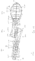
図1は、約193nm紫外作動波長のために構成された本発明によるカタディオプトリック投影レンズ100の第1実施例を示す。これは、平面状の物体面OS(物体面)に配置されたレチクル上のパターンの像を、平面状の像面IS(像面)に例えば4:1の縮小スケールで投影するために構成されており、ちょうど2つの実中間像IMI1、IMI2を生成している。第1屈折対物系部分OP1は、物体面のパターンを第1中間像IMI1に拡大スケールで結像するために構成されている。第2反射光学(純粋反射)対物系部分OP2は、IMI2を1:1に近い倍率で結像する。第3屈折対物系部分OP3は、第2中間像IMI2を像面IS上に強い縮小比で結像する。第2対物系部分OP2は、物体側を向いた凹面鏡面を有する第1凹面鏡CM1と、像側を向いた凹面鏡面を有する第2凹面鏡CM2を含む。これらの鏡面は両方とも連続的又は完全であり、すなわちそれらは穴又は孔を有していない。これらの互いに対向した鏡面は、カタディオプトリックキャビティを画定し、これは鏡間空間とも呼ばれていて、凹面鏡によって画定された曲面により囲まれている。中間像IMI1、IMI2は、鏡面から充分離れていて、カタディオプトリックキャビティの内側に両方とも位置する。
FIG. 1 shows a first embodiment of a
凹面鏡の各鏡面は、物理的な鏡面の縁を越えて延び、鏡面を有する数学的な面である「湾曲面」又は「湾曲の面」を画定する。第1及び第2凹面鏡は、共通の回転対称軸を有する回転対称湾曲面の部分である。 Each mirror surface of the concave mirror extends beyond the edge of the physical mirror surface and defines a “curved surface” or “curved surface” that is a mathematical surface having a mirror surface. The first and second concave mirrors are portions of a rotationally symmetric curved surface having a common rotational symmetry axis.
対物系100は、回転対称であり、全ての屈折及び反射光学コンポーネントに共通な1つの真っ直ぐな光軸AXを有する。折り曲げ鏡は存在しない。凹面鏡は、小さな直径を有していて、それらを一緒に近くに置き、それらの間にある中間像のかなり近くに置くことを可能にしている。これらの凹面鏡は両方とも軸方向対称面の軸外部分として構成されて照明される。光ビームは、口径食なしで、光軸を向いたこれらの凹面鏡の縁のそばを通過する。
The
投影対物系100は、例えば純水のような高屈折率液浸液と共に使用されるとき、像面ISに最も近い対物系の射出面と像面ISの間で、像側開口数NA=1,2を有するλ=193nmの液浸対物系として構成されている。屈折第1対物系部分OP1は、球面レンズのみを有する。凹面鏡CM1、CM2は両方とも非球面鏡である。第3対物系部分OP3は、その対物系部分の瞳面P3の位置(結像の主光線CRが光軸AXと交差する場所)の近くの1つの非球面(レンズL3−9の入射面)と、最終の像側平凸レンズL3−13の直ぐ上流にある最終から2番目のレンズL3−12の射出側の第2非球面を有する。最終レンズは、投影対物系の動作時において液浸液と接触し、この明細書において「液浸レンズ」とも呼ばれる。投影対物系は全ての収差に対して充分に補正されるわけではないが、第3レンズ部分に全て置かれた少数の非球面レンズ(NAS=2)で結像が可能であることが見て取れる。
When the
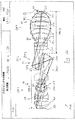
図2は、全て球面の第1対物系部分OP1と第3対物系部分OP3の1つだけの非球面レンズL3−4を有する対物系200の第2実施例を示す。開口絞りASは、第3対物系部分のその瞳面PS3の領域に設けられている。この場合4つのレンズだけからなり、全てのレンズが正の球面レンズである第1対物系の開口絞りのために良く補正された位置は必要ではない。これにより第1対物系部分の非常に単純でコンパクトな構成が得られる。
FIG. 2 shows a second embodiment of an
投影対物系200は、高屈折率液浸液、例えば純水と共に使用されるとき、対物系の射出面と像面の間で、像側開口数NA=1,20を有するλ=193nmの液浸レンズとして構成されている。この構成のための仕様が表2にまとめられている。最も左の欄は、屈折、反射、又は他に明示された面の番号を示し、第2欄は、その面の半径r[mm]を示し、第3欄は、光学素子の「厚さ」と呼ばれるパラメータである面と次の面の間の距離d[mm]を示し、第4欄はその光学素子を製造するために用いられた材料を示し、第5欄はその製造のために使用された材料の屈折率を示す。第6欄は、光学素子の光学的に利用可能な有効半直径[mm]を示す。表中の半径r=0は、(無限半径を有する)平面状の面を意味する。
When used with a high refractive index immersion liquid, such as pure water, the
この特定の実施例の場合においては、3つの面(面9、10、18)が非球面である。表2Aはこれらの非球面のための関連データを示し、そこから、それらの面図形のサジッタ又は立ち上がり高さp(h)が高さhの関数として次の式を用いて算出され得る。 In this particular embodiment, the three surfaces (surfaces 9, 10, 18) are aspheric. Table 2A shows the relevant data for these aspheric surfaces, from which the sagittal or rising height p (h) of those surface features can be calculated using the following equation as a function of height h.
p(h)=[((1/r)h2)/(1+SQRT(1−(1+K)(1/r)2h2))]+C1・h4+C2・h6+....,
ここで半径の逆数(1/r)は、面頂点での当該面の曲率であり、hは光軸からその点までの距離である。サジッタ又は立ち上がり高さp(h)は、こうして、z方向に沿って、すなわち光軸に沿って計測された当該面の頂点からその点までの距離を表す。定数K、C1、C2等は、表2Aに示されている。
p (h) = [((1 / r) h 2 ) / (1 + SQRT (1− (1 + K) (1 / r) 2 h 2 ))] + C1 · h 4 + C2 · h 6 +. . . . ,
Here, the reciprocal of the radius (1 / r) is the curvature of the surface at the surface vertex, and h is the distance from the optical axis to that point. The sagittal or rising height p (h) thus represents the distance from the vertex of the surface measured along the z direction, ie along the optical axis, to the point. The constants K, C1, C2, etc. are shown in Table 2A.
この実施例において、非球面凹面鏡CM1、CM2に加えて少数のレンズ(NL=13)と1つの非球面レンズ(L3−4)のみで、多くの収差が高度に補正されるのは注目に値する。とくに全ての3次及び5次収差がゼロである。テレセントリシティの変化は、その視野に渡って補正される。高次(7次以上)の歪曲がその視野に渡って補正される。像側での瞳収差が補正されて、像側開口数NA=1,2がその視野に渡って一定であるようになっている。2つの実光線は軸上で補正され、4つの開口光線は中間視野点で補正される。高次(7次以上)の非点収差が視野の縁と中間視野点で補正される。この補正状況は、(焦点レンズ群として作動する)最も大きいレンズにおいて直径218mmである第3対物系部分のレンズ直径がかなり小さい対物系で得られる。第3対物系部分の第1レンズL3−1は、幾何学的に最も近い鏡(第1凹面鏡CM1)の頂点に対して比較的大きな幾何学的距離を有し、その軸方向鏡−レンズ距離MLDは90mmである。これは物体面OSと像面ISの間の軸方向距離の約7.5%であり、この物体−像距離は「トラック長さ」とも呼ばれる。像側第1凹面鏡CM1と第3対物系部分の第1レンズの間の大きな幾何学的距離MLDは、第3対物系部分における小さなレンズ直径に寄与する。 In this embodiment, it should be noted that many aberrations are highly corrected by only a small number of lenses (N L = 13) and one aspheric lens (L3-4) in addition to the aspherical concave mirrors CM1 and CM2. Deserve. In particular, all third-order and fifth-order aberrations are zero. The change in telecentricity is corrected over the field of view. Higher order (seventh or higher order) distortion is corrected over the field of view. The pupil aberration on the image side is corrected so that the image-side numerical apertures NA = 1 and 2 are constant over the field of view. Two real rays are corrected on the axis, and four aperture rays are corrected at the intermediate field point. Higher-order (seventh-order and higher) astigmatism is corrected at the field edge and intermediate field point. This correction situation is obtained with an objective system in which the lens diameter of the third objective part, which is 218 mm in diameter at the largest lens (operating as a focal lens group) is considerably small. The first lens L3-1 of the third objective part portion has a relatively large geometric distance with respect to the vertex of the geometrically closest mirror (first concave mirror CM1), and its axial mirror-lens distance. The MLD is 90 mm. This is about 7.5% of the axial distance between the object plane OS and the image plane IS, and this object-image distance is also referred to as “track length”. A large geometric distance MLD between the image-side first concave mirror CM1 and the first lens of the third objective part contributes to a small lens diameter in the third objective part.
像側の最終レンズL3−9(液浸レンズ)は、短い半径(50mm)の球状入射面を有しており、これにより小さな入射角度がその面で得られる。 The final lens L3-9 (immersion lens) on the image side has a spherical incident surface with a short radius (50 mm), whereby a small incident angle is obtained on that surface.
この構成は、より高次のペッツバル湾曲とより高次のサジッタ軸外球面収差が支配的であるのが明らかである残留収差に関して最適化されることが可能である。第1対物系部分に1つのレンズを加えること及び/又は1以上の更なる非球面を設けることが、残留収差を減少させるのに寄与する。図2の構成の更なる発展の例が図3に示されており、そこでは像側の凹面を有するメニスカスレンズとして構成された追加の負レンズL1−4が、その瞳面P1と第1中間像の間で第1対物系部分に加えられている。この修正は、先述の残留収差を補正することを可能にする。この例は、とりわけ、基本的な構成が、少数のレンズと少数の非球面レンズの全体的に単純な構成で、結像誤差を補正するための高い柔軟性を可能にすることを例示している。 This configuration can be optimized for residual aberrations where it is clear that higher order Petzval curvature and higher order sagittal off-axis spherical aberration are dominant. Adding one lens to the first objective part and / or providing one or more additional aspheric surfaces contributes to reducing residual aberrations. An example of a further development of the configuration of FIG. 2 is shown in FIG. 3, in which an additional negative lens L1-4 configured as a meniscus lens with a concave surface on the image side is connected to its pupil plane P1 and a first intermediate Between the images is added to the first objective part. This correction makes it possible to correct the aforementioned residual aberration. This example illustrates, among other things, that the basic configuration allows a high degree of flexibility to correct imaging errors with an overall simple configuration of a small number of lenses and a small number of aspheric lenses. Yes.
投影対物系400の第4実施例が図4に示されており、その仕様が表4と4Aに与えられている。図2及び3の実施例と同様に、1つだけの非球面レンズ、すなわち非球面射出面を有する正のメニスカスレンズL3−4が、この系において、第3対物系部分OP3におけるその対物系部分の瞳面P3に光学的に近い開口絞りASの上流の最も大きなビーム直径の領域に置かれている。第1対物系部分OP1は、全て球面であり、P−P−P−N−Pのシーケンスにおいて負レンズL1−4を1つだけ有し、ここで「P」は、正レンズを意味し、「N」は負レンズを意味する。構成の観点から、像側凹面鏡CM1と第3レンズ部分OP3の第1レンズL3−1の間の大きな軸方向距離が明らかであり、この距離MLDは、トラック長さの10%よりも大きい。
A fourth embodiment of the
図5は、図3及び4の系の変形例を示し、そこでは主に第1対物系部分OP1における僅かな修正が、改良された補正に活用されている。図5の結果としての構成は、2つの視野点を有し、これらは非点収差とペッツバル湾曲の両方のために補正され、非点収差を有さない視野ゾーンが焦点の合った状態となる。 FIG. 5 shows a variant of the system of FIGS. 3 and 4, in which a slight modification mainly in the first objective part OP1 is exploited for improved correction. The resulting configuration of FIG. 5 has two field points, which are corrected for both astigmatism and Petzval curvature, so that the field zone without astigmatism is in focus. .
本発明のより好ましい構成において、視野に対する歪曲、非点収差、ペッツバル湾曲及びテレセントリシティ変化は、(第1中間像IMI1を形成するリレー系の役割を果たす)第1対物系部分OP1と非球面鏡に加えていくつかの球面レンズの同様な構成で、非常に高次まで全て補正され得る。 In a more preferred configuration of the present invention, the distortion, astigmatism, Petzval curvature and telecentricity change with respect to the field of view are the first objective part OP1 and the aspherical mirror (acting as a relay system for forming the first intermediate image IMI1). In addition, with similar configurations of several spherical lenses, all can be corrected to very high orders.
2つの非球面鏡CM1、CM2は、少数の非球面レンズで良好な補正を得るのに重要なのが明らかである。2つの非球面鏡は、一般に、歪曲及びテレセントリシティ変化のような2つの主光線収差が非常に高次まで補正される構成を可能にする。もし2つの非球面鏡の変形が正確に設定されるなら、これらの2つの収差がこれらの鏡により正確に補正され得る。1つの注目に値する点は、追加的に、全て球面の第1対物系部分OP1で非点収差とペッツバル湾曲が高度に補正され得ることである。 Obviously, the two aspherical mirrors CM1 and CM2 are important for obtaining good correction with a small number of aspherical lenses. Two aspheric mirrors generally allow a configuration in which two principal ray aberrations such as distortion and telecentricity changes are corrected to very high orders. If the deformations of the two aspherical mirrors are set correctly, these two aberrations can be accurately corrected by these mirrors. One notable point is that, in addition, astigmatism and Petzval curvature can be highly corrected in the first spherical objective part OP1.
単独で又は組み合わせで、収差補正に関する構成の種類の正の特性に寄与し得る少なくとも3つの特徴があることが明らかである。1つの態様は、凹面鏡CM1、CM2が同一又はほぼ同一である他の実施例と比較して、凹面鏡が、好ましくは半径に関して非常に異なっていてよいことである。更に、中間像IMI1及び/又はIMI2での多くのコマ収差が、少数の非球面レンズでの補正を容易にすることが明らかである。また、像側凹面鏡CM1の頂点と第3対物系部分の第1レンズの間の著しく大きなエアスペース(鏡−レンズ距離MLD)は、有利な特性に寄与するのが明らかである。 It is clear that there are at least three features that can contribute to the positive characteristics of the type of configuration for aberration correction, alone or in combination. One aspect is that the concave mirrors may preferably be very different in terms of radius compared to other embodiments where the concave mirrors CM1, CM2 are identical or nearly identical. Furthermore, it is clear that many coma aberrations in the intermediate images IMI1 and / or IMI2 facilitate correction with a small number of aspheric lenses. It is also clear that a significantly large air space (mirror-lens distance MLD) between the apex of the image-side concave mirror CM1 and the first lens of the third objective part contributes to advantageous properties.
物体側及び像側及び/又は投影対物系、すなわち第1対物系部分OP1および第3対物系部分OP3は、独立して構成され得ることも明らかである。とくに、第3対物系(焦点レンズ群)は、視野収差に多くの注意を払うことなく、開口収差に対して構成されることが可能であり、構成に関して比較的単純である第1対物系部分は、視野収差を補償するために構成されることが可能であり、その補償は非球面レンズ無しで、又は少数の非球面レンズのみで、例えば1つの非球面レンズのみで、得られるだろう。 It is also clear that the object side and the image side and / or the projection objective, i.e. the first objective part OP1 and the third objective part OP3, can be configured independently. In particular, the third objective system (focus lens group) can be configured for aperture aberration without paying much attention to field aberrations, and is relatively simple with respect to the configuration. Can be configured to compensate for field aberrations, which compensation could be obtained without an aspheric lens or with only a few aspheric lenses, for example with only one aspheric lens.
先の実施例は、全てのレンズが球面であってもよい4つ又は5つのレンズのみのかなり単純な第1対物系部分を有する構成が利用可能であることを示している。このようなかなり単純なリレーレンズ群は、極めて高次まで視野収差に対して補正することができる。開口収差は好ましくは第3対物系部分で補正され、第3対物系部分はいくつかの非球面だけのかなり単純な構成を有してもよく、第3対物系部分における非球面レンズの個数は、好ましくは第1対物系部分における非球面レンズの個数よりも大きい。 The previous example shows that a configuration with a fairly simple first objective part of only four or five lenses, where all lenses may be spherical, is available. Such a fairly simple relay lens group can correct for field aberrations to very high orders. The aperture aberration is preferably corrected in the third objective part, which may have a fairly simple construction with only a few aspheric surfaces, and the number of aspheric lenses in the third objective part is Preferably, it is larger than the number of aspheric lenses in the first objective part.
図6及び7は、密接に関連した実施例600、700を示し、そこでは屈折第1及び第3対物系部分における非球面レンズの個数は、先の実施例と比較して増加している。対物系700の仕様は、表7及び7Aに与えられている。開口収差に関する改良が得られる。とくに、7つの非球面レンズが使用され、そこでN1AS=2及びN3AS=5であり、非球面レンズ比ASR=0.4となっている。第1対物系部分OP1において2つの非球面レンズL1−2及びL1−5を有する図6の構成は、その視野に渡って5ミリ波の波面収差を有する。
FIGS. 6 and 7 show closely
1つの2重非球面DAが、第3対物系部分OP3において、著しく増大するビーム直径の領域で、光学的に第2中間像IMI2と対物系部分の瞳面P3の間に設けられている。2重非球面は、正レンズL3−6の非球面射出面と、そこの直近に続く正メニスカスレンズL3−7の非球面入射面により形成されている。2つの非球面の軸方向距離は、2重非球面に隣接するより薄い方のレンズL3−7の厚さよりも小さく、非球面は接近している。これにより、屈折力の合成放射分布が、ビームの特定領域で得られ、こうして像の補正に強く寄与する。 One double aspheric surface DA is optically provided between the second intermediate image IMI2 and the pupil plane P3 of the objective system part in the region of the beam diameter that increases remarkably in the third objective system part OP3. The double aspherical surface is formed by the aspherical exit surface of the positive lens L3-6 and the aspherical incident surface of the positive meniscus lens L3-7 that immediately follows the double aspherical surface. The axial distance between the two aspheric surfaces is smaller than the thickness of the thinner lens L3-7 adjacent to the double aspheric surface, and the aspheric surfaces are close to each other. Thereby, a combined radiation distribution of refractive power is obtained in a specific region of the beam, thus contributing strongly to image correction.
図8及び9は、構成が非常に類似する実施例800、900を示す。投影対物系900の仕様が表9、9Aに与えられている。像側開口数NA=1,2であり、約6ミリ波の波面誤差が6つの非球面レンズのみで得られ、そこでは1つの非球面レンズ(瞳面P1の近くに置かれた像側凹面を有する正メニスカスL1−5)が第1対物系部分に設けられ、残りの5つの非球面レンズは、第3対物系部分OP3内に分散されている。これらの非球面レンズは、両凹負メニスカスL3−2と、レンズペアL3−5、L3−6が非球面を対向させることにより形成された2重非球面DAと、開口絞りAPに近い両凸正レンズL3−9と、開口絞りと像面ISの間の正レンズL3−10を有する。図8の光線分布に示されるように、第1対物系部分OP1により形成されたリレー部分の前側瞳は、かなり良く補正される。中間像IMI1及びIMI2の両方に対してコマ収差がほとんど又は全く無い焦点領域(低コマ収差中間像)が明らかである。低コマ収差中間像IMI2は、入射側にある厚い正レンズL3−1と、第1レンズL3−1と開口絞りASの僅かに上流の最大ビーム直径の領域との間の著しいウエストW(すなわちビーム直径のくびれ領域)を有する屈折対物系部分OP3によって、像面上に再度焦点合わせされる。2重非球面DAは、ウエストと開口絞りASの間の発散ビーム内に設けられている。
Figures 8 and 9 show examples 800, 900 that are very similar in construction. The specifications of the
図10の投影対物系1000は、幾つかの点において、図8及び9に示された実施例の変形として考えられてもよい。その仕様が表10、10Aに与えられている。第3対物系部分OP3は、5つの非球面レンズを有し、実施例800及び900と比較すると、比較的類似の構成および配置を有するが、第1対物系部分OP1に非球面レンズはなく、NAS=5となっている。注目すべきことに、正レンズの直ぐ下流での物体側凹面を有する負メニスカスレンズL1−7と像側両凸正レンズL1−6からなる全て球面のダブレットが、瞳面P1の近くに位置付けられている。正レンズL1−6から射出してそれに続く負レンズL1−7に入射する光線の高い入射角度がこの領域に与えられ、その入射角度は60°より大きい角度を含む。急激な傾斜変化を有する非球面を製造することの困難性を有する実施例800、900の非球面レンズL1−5の光学的効果は、かなり高い入射角度(60°−65°の範囲)を使用して、第1対物系部分OP1の瞳面の近くの同様な領域で、少なくとも部分的にシミュレートされ得ることが明らかである。ダブレットレンズL1−6、L1−7の球面の製造はより容易であるため、時には、高い入射角度が生じる1以上のレンズ面で非球面レンズを置き換えることにより、製造のしやすさが向上し得る。
The
非球面を複数の球面で置き換えることを考える場合、最も重要なことはベースの球面曲率であるのは明らかである。球面ダブレットは、それゆえ、非球面−非常に高次の非球面でさえ−を置き換えできるだろう。 When considering replacing an aspherical surface with multiple spherical surfaces, it is clear that the most important thing is the spherical curvature of the base. Spherical doublets could therefore replace aspheric surfaces-even very high order aspheric surfaces.
実施例1000の変形例の補正状況が、その視野に渡って4、5ミリ波と6ミリ波の間にある。これが示唆していることは、この補正が全て球面の第1対物系部分OP1で得られることが可能であり、良好な性能を得るために完全な構成は、多くの非球面レンズを必要としないことである(ここでは5つのレンズ非球面のみ)。 The correction status of the variation of Example 1000 is between 4, 5 and 6 millimeter waves across its field of view. This suggests that this correction can all be obtained with the first objective part OP1 of the sphere, and the complete configuration does not require many aspheric lenses to obtain good performance. (Here, only 5 lens aspheric surfaces).
カタディオプトリック投影対物系1100の仕様は、表11、11Aに与えられている。実施例は、互いに非常に近くにある2つのかなり強い非球面レンズ面を有する「2重非球面」が、非常に強力な構成コンポーネントであってもよいことを示す良い例である。ここで、レンズL3−4及びL3−5により形成される2重非球面DAは、例えば図8、9、及び10で示される実施例と同様に、第3対物系部分OP3内で増加するビーム直径の領域にある。加えて、レンズL1−5及びL1−6の対向する面によって形成された第2の2重非球面DAは、前側瞳、すなわち第1対物系部分OP1の瞳面P1の光学的に近くに存在する。この実施例において、NAS=8、N1AS=3及びN3AS=5である。補正は、第3対物系部分において開口絞りASの近くにある220mmの最大レンズ直径で、NA=1,2で約2,5ミリ波のみである。これは、この構成が、少数の非球面レンズで良好な光学的性能を得る可能性を例示している。 The specifications of the catadioptric projection objective 1100 are given in Tables 11 and 11A. The example is a good example showing that a “dual aspheric surface” with two fairly strong aspheric lens surfaces that are very close to each other may be a very powerful component. Here, the double aspheric surface DA formed by the lenses L3-4 and L3-5 is a beam that increases in the third objective part OP3, for example, as in the embodiments shown in FIGS. In the area of diameter. In addition, the second double aspheric surface DA formed by the opposing surfaces of the lenses L1-5 and L1-6 exists optically close to the front pupil, that is, the pupil plane P1 of the first objective part OP1. To do. In this example, N AS = 8, N1 AS = 3 and N3 AS = 5. The correction is a maximum lens diameter of 220 mm near the aperture stop AS in the third objective part, with NA = 1, 2 and only about 2.5 millimeter waves. This illustrates the potential for this configuration to obtain good optical performance with a small number of aspheric lenses.
図12は、(先の例におけるNA=1,2ではなく)NA=1,3を有するλ=193nmの液浸対物系を示す。(第3対物系部分OP3において開口絞りASの直ぐ上流にある)最大レンズ直径は270mmである。N1AS=2及びN3AS=6のちょうど8個の非球面レンズがある。これらは、レンズL3−4及びL3−5により形成され、第3対物系部分のウエストWと開口絞りASの間の発散ビームの領域に位置付けられた1つの2重非球面DAを含む。視野半径は66mmである。補正はその視野に渡って約4から6ミリ波である。その構成は、厳密にテレセントリックな入力を仮定している。中間像における光線の構成から、中間像において大きな量のコマ収差が存在するのは明白である。 FIG. 12 shows a λ = 193 nm immersion objective with NA = 1,3 (rather than NA = 1,2 in the previous example). The maximum lens diameter (which is immediately upstream of the aperture stop AS in the third objective part OP3) is 270 mm. There are exactly 8 aspheric lenses with N1 AS = 2 and N3 AS = 6. These are formed by lenses L3-4 and L3-5 and include one double aspheric surface DA located in the area of the diverging beam between the waist W of the third objective part and the aperture stop AS. The field radius is 66 mm. The correction is about 4 to 6 millimeters over its field of view. The configuration assumes a strictly telecentric input. From the composition of the rays in the intermediate image, it is clear that there is a large amount of coma in the intermediate image.
NA=1,3のカタディオプトリック液浸対物系1300の更なる実施例が図13に示されている。その仕様は表13、13Aに与えられている。NAS=10、N1AS=4及びN3AS=6である。像側開口数NA=1,3は対物系1200のそれに対応しているが、最大レンズ直径は、(実施例1200における270mmではなく)250mmに過ぎない。依然として、波面誤差はその視野に渡ってのみ4ミリ波である。その構成もまた、実絞りの欠如により特徴付けられていて、テレセントリックな入力が要求されるようになっている。大きな量のコマ収差もまた中間像において存在する。
A further embodiment of a
図14におけるカタディオプトリック液浸対物系1400(仕様は表14及び14Aで与えられる)は、NA=1,3と比較的小さい最大レンズ直径を有する高NAカタディオプトリック液浸対物系のもう1つの例であり、その最大レンズのレンズ直径は250mmに過ぎない。11のうちの4つの非球面レンズが第1対物系部分OP1にあり、残りの7つの非球面レンズは第3対物系部分内に分散されている。先の構成と比較すると、非球面レンズの製造のしやすさは、全ての非球面レンズ面が1,0mm未満で球面から変形しており、各非球面に対して150mmより大きい局所非球面半径を有するという要求条件に従うことにより向上する。3つの2重非球面が設けられる。第1対物系部分OP1内で瞳面P1に位置付けられたレンズL1−6及びL1−7により形成された、1つの2重非球面DAは、かなり高い入射角度を有するように構成されており、これは短い局所非球面半径(これは製造がより困難である)と同様な効果を有するのが明らかである。第3対物系部分OP3には2つの2重非球面DA、すなわち第3対物系部分内で最小レンズ直径の領域の負レンズL3−1、L3−2の対向する面により形成された1つの2重非球面と、最大ビーム直径の領域と像面ISの間に位置付けられた開口絞りASと第2中間像IMI2の間の最大ビーム直径増加の領域におけるレンズL3−3及びL3−4の対向する面により形成された、1つの2重非球面に続く2重非球面がある。図11から13の実施例のように、大きな量のコマ収差が中間像IMI1、IMI2において存在する。
The
図15におけるカタディオプトリック液浸対物系1500(仕様は表15及び15A)は、図14に示された実施例の変形である。対物系1500に存在するレンズの寸法及び種類は、本質的に同じである。追加の両凸正レンズL3−1が第2中間像IMI2の直後に導入されていて、これにより第3対物系部分OP3の入射側に正の屈折力を提供するという点で、違いがある。NA=1,3での良好な性能が得られる。
The catadioptric immersion objective 1500 (specifications Tables 15 and 15A) in FIG. 15 is a variation of the embodiment shown in FIG. The dimensions and types of lenses present in the
基本構成は、NA=1,3で、より高い像側開口数の可能性を有する。図16におけるカタディオプトリック液浸対物系1600(仕様は表16及び16A)は、図15の構成に基づいているが、NA=1,35を得るために最適化されている。この実施例におけるように、第1対物系部分には(4つの非球面レンズを含む)10のレンズが、第3対物系部分には(7つの非球面レンズを含む)12のレンズがある。これらのレンズの基本的な種類は同じであるが、レンズ厚さ、面半径及びレンズ位置は僅かに異なる。開口数が増大するにつれて、開口絞りASを、第3対物系OP3において最大ビーム直径の領域(両凸レンズL3−8)と像面ISの間の強くビームを収束させる領域に置くのが有利であることが明らかである。ここで、3つの正レンズのみが、開口絞りと像面の間に置かれる。
The basic configuration is NA = 1,3 and has the possibility of higher image side numerical aperture. The
所望の開口数が高ければ高いほど、第2対物系部分OP2を像面の幾何学的に近くに置くのが有利だろう。便宜のために、好ましくは2つの非球面凹面鏡CM1、CM2だけからなる第2対物系部分OP2は、以下で「鏡群」とも呼ぶ。この特徴を説明する目的で、第1光軸長さOAL1が、物体面に幾何学的に最も近い凹面鏡CM2の頂点と物体面OSの間で画定され、第3光軸長さOAL3が、像面に幾何学的に最も近い凹面鏡(CM1)の頂点と像面の間で画定される(図16を参照)。この定義に基づいて、鏡群位置パラメータMG=OAL1/OAL3が定められ、この値が大きくなると、鏡群が投影対物系の更に像側に位置付けられる。表17において、OAL1、OAL3及びMGの値は、ここで説明された全ての実施例をまとめたものである。これらのデータに基づけば、鏡群位置パラメータMG>0,7は、高い像側開口数を得る目的で望ましいことは明らかである。好ましくは、MG≧0,8である。より好ましくは、MG≧0,9である。 The higher the desired numerical aperture, the more advantageous it is to place the second objective part OP2 closer to the image plane geometry. For convenience, the second objective part OP2, which preferably consists of only two aspheric concave mirrors CM1, CM2, will also be referred to below as “mirror group”. For the purpose of explaining this feature, a first optical axis length OAL1 is defined between the vertex of the concave mirror CM2 geometrically closest to the object plane and the object plane OS, and a third optical axis length OAL3 is defined as an image. It is defined between the vertex of the concave mirror (CM1) geometrically closest to the plane and the image plane (see FIG. 16). Based on this definition, a mirror group position parameter MG = OAL1 / OAL3 is determined, and when this value increases, the mirror group is positioned further on the image side of the projection objective. In Table 17, the values of OAL1, OAL3, and MG summarize all the examples described herein. Based on these data, it is clear that the mirror group position parameter MG> 0, 7 is desirable for the purpose of obtaining a high image-side numerical aperture. Preferably, MG ≧ 0.8. More preferably, MG ≧ 0.9.
ここで説明された各投影対物系は、投影放射線が射出面ESにおいて投影対物系から射出する高NA像側端部を有し、射出面ESは、像面ISに配置された平面状の基板面と射出面の間で均一な距離を可能にするために、好ましくは平面である。像面に最も近くて射出面ESを形成するレンズは、ここでは「最終レンズ」LLと呼ばれる。好ましくは、最終レンズは、ほとんどの実施例で球面状に湾曲した、湾曲した入射面ENSと平面状の射出面を有する平凸正レンズである。高NAを得る目的で、湾曲した入射面ENSにより与えられる大きな屈折力が可能な限り像面に近くに配置されるように、最終レンズを構成するのが有利であることが分かった。更に、最終レンズLLの入射面ENSの大きな曲率、すなわち小さい曲率半径が望ましいのが明らかである。TLLが光軸上の最終レンズの厚さ(すなわち光軸に沿って測定された入射面ENSと射出面ESの間の軸方向距離)であり、RLLが最終レンズの物体側頂点半径(すなわち入射面ENSの半径)であり、DIALLが最終レンズの入射面の光学的自由直径である場合、パラメータLL1=TLL/RLLとLL2=DIALL/RLLは好ましくは一定の範囲内に入るべきである。とくに、もし条件0,46≦LL1≦0,69がLL1に当てはまるなら、それが有利であることが分かった。パラメータLL1は、入射面の曲率の中心が射出面と一致する半球レンズで1になるため、LL1に関する条件は、湾曲した入射面の曲率の中心が最終レンズの外側にとくに像面を越えて存在する、非半球の最終レンズが好ましいことを示している。 Each projection objective described here has a high NA image side end where projection radiation emerges from the projection objective at the exit plane ES, which is a planar substrate disposed on the image plane IS. A plane is preferred to allow a uniform distance between the surface and the exit surface. The lens that forms the exit surface ES closest to the image plane is referred to herein as the “final lens” LL. Preferably, the final lens is a plano-convex positive lens having a curved entrance surface ENS and a planar exit surface, which is curved spherically in most embodiments. For the purpose of obtaining a high NA, it has been found advantageous to configure the final lens so that the large refractive power provided by the curved entrance surface ENS is located as close as possible to the image plane. Furthermore, it is clear that a large curvature of the entrance surface ENS of the final lens LL, that is, a small radius of curvature is desirable. T LL is the thickness of the final lens on the optical axis (that is, the axial distance between the entrance surface ENS and the exit surface ES measured along the optical axis), and R LL is the object-side apex radius of the final lens ( That is, the radius of the incident surface ENS), and DIA LL is the optical free diameter of the incident surface of the final lens, the parameters LL1 = T LL / R LL and LL2 = DIA LL / R LL are preferably within a certain range. Should enter. In particular, it has been found to be advantageous if the conditions 0, 46 ≦ LL1 ≦ 0,69 apply to LL1. Since the parameter LL1 is 1 for a hemispherical lens whose center of curvature of the entrance surface coincides with the exit surface, the condition regarding LL1 is that the center of curvature of the curved entrance surface exists outside the final lens, particularly beyond the image plane. This indicates that a non-hemispheric final lens is preferred.
交替的に、又は追加的に、条件1,15≦LL2≦1,67は、好ましくはLL2に当てはまるべきである。LL1及びLL2のためのそれぞれの値が表18に示されている。もし上記条件の少なくとも1つが当てはまるなら、最終レンズの湾曲した入射面により与えられる大きな正の屈折力が像面の近くに与えられ、これにより大きな像側開口数NAが、とくにNA>1,1又はNA>1,2で、NA=1,3又はNA=1,35のように、得られることが可能となる。
Alternately or additionally, the
中間像IMI1、IMI2の補正状況に関して、幾つかの実施例において、両方の中間像が本質的に焦点合わせされ(すなわち多くの収差が高度に補正され)、他の実施例においてかなりの収差、とくにコマ収差が生じることが分かった(図11−16を比較)。第2中間像IMI2のかなりのコマ収差が、対物系の全体的な補正に関して有利であってもよい。凹面鏡CM1及びCM2からなるカタディオプトリック第2対物系部分は、第1中間像を第2中間像に本質的に対称なやり方で結像するのに有効であるため、通常はカタディオプトリック第2対物系部分によりわずかなコマが導入されるに過ぎない。それゆえ、両方の中間像のコマに関する補正状況は類似する傾向にある。幾つかの実施例において、少なくとも第2中間像に対するかなりの量のコマ収差が、全体的な補正にかなり寄与することが明らかである。次の説明がこの点に関して注目に値する。 Regarding the correction situation of the intermediate images IMI1, IMI2, in some embodiments both intermediate images are essentially focused (ie many aberrations are highly corrected) and in other embodiments considerable aberrations, in particular It was found that coma aberration occurs (compare FIGS. 11-16). A considerable coma aberration of the second intermediate image IMI2 may be advantageous with respect to the overall correction of the objective system. Since the catadioptric second objective part consisting of the concave mirrors CM1 and CM2 is effective for imaging the first intermediate image in a manner essentially symmetrical to the second intermediate image, it is usually the second catadioptric second object. Only a few frames are introduced by the objective part. Therefore, the correction statuses for the frames of both intermediate images tend to be similar. In some embodiments, it is apparent that a significant amount of coma at least for the second intermediate image contributes significantly to the overall correction. The following explanation is noteworthy in this regard.
対物系全体の正弦条件の補正は、とくに非常に高い像側NAを有する対物系に対して、難しい。正弦条件の補正は、中間像のコマ収差により容易にすることができる。高NAの像面から低NAの物体面への(すなわちリソグラフィにおける投影対物系の意図された使用と比較すると逆方向の)結像を考える場合、(放射線が入射する)第3対物系部分は、一定の補正状況を有する中間像を提供する。この結像の球面収差が補正されると仮定すると、この結像の正弦条件が補正される場合は、中間像は本質的にコマ収差のない状態となる。対照的に、正弦条件が補正されない場合は、その中間像はかなりの量のコマ収差を有する。中間像がかなりの量のコマ収差を有する場合、第3対物系部分における正弦条件の補正が容易にされる。 Correction of the sine condition of the entire objective system is difficult, especially for an objective system with a very high image side NA. Correction of the sine condition can be facilitated by the coma of the intermediate image. When considering imaging from a high NA image plane to a low NA object plane (ie in the opposite direction compared to the intended use of the projection objective in lithography), the third objective part (incident by radiation) is Provide an intermediate image having a certain correction situation. Assuming that the spherical aberration of this image is corrected, if the sine condition of this image is corrected, the intermediate image is essentially free of coma. In contrast, if the sine condition is not corrected, the intermediate image has a significant amount of coma. If the intermediate image has a significant amount of coma, correction of the sine condition in the third objective part is facilitated.
ここで、第2中間像の像面への(高NA端部に向けた)意図された方向における結像を考える。もし第2中間像が、とくにコマ収差無しで、良好な補正状況を有するなら、正弦条件の全体的な補正は、第2中間像を像面上に結像する第3対物系部分により影響を受けなければならないだろう。対照的に、もし一定量のコマ収差が第2中間像に存在するなら、第3対物系部分は、より緩和された形で構成されることが可能である。これは、正弦条件の補正は、第3対物系部分の光学的に上流の対物系部分、すなわち第1中間像を形成する屈折リレー系OP1と、カタディオプトリック第2対物系部分OP2により、少なくとも部分的に影響を受け得るからである。それゆえ、コマの補正が第1屈折対物系部分OP1と第3対物系部分OP3の間に分布する構成は、屈折対物系部分の各々がコマ収差に対して独立して補正される構成の対物系と比較したときに、有利であることができることは明らかである。 Now consider imaging in the intended direction (towards the high NA end) on the image plane of the second intermediate image. If the second intermediate image has a good correction situation, in particular without coma, the overall correction of the sine condition is influenced by the third objective part that forms the second intermediate image on the image plane. You will have to take it. In contrast, if a certain amount of coma is present in the second intermediate image, the third objective part can be configured in a more relaxed manner. This is because the correction of the sine condition is performed at least by the objective part optically upstream of the third objective part, that is, the refractive relay system OP1 forming the first intermediate image and the catadioptric second objective part OP2. It can be partially affected. Therefore, the configuration in which the correction of the coma is distributed between the first refractive objective part OP1 and the third objective part OP3 has an objective in which each of the refractive objective parts is corrected independently of the coma aberration. Obviously, it can be advantageous when compared to the system.
先に述べられたように、本発明は、コンパクトな寸法でNA>1での液浸リソグラフィに適した高NAの投影対物系を構成可能にする。 As previously mentioned, the present invention allows the construction of a high NA projection objective suitable for immersion lithography with compact dimensions and NA> 1.
表19は、コンパクト性パラメータCOMP1、COMP2、COMP3を計算するために必要な値と、各々の系についてのこれらのパラメータの各値をまとめたものは、仕様の表で表されている(表の番号(同じ番号の図に対応する)が表19の欄1に与えられている)。更に、N1AS、N3AS、及びASRの各値が示されている。
Table 19 shows the values required to calculate the compactness parameters COMP1, COMP2, COMP3 and a summary of the values of these parameters for each system in the specification table (Table of Tables). Numbers (corresponding to the same numbered figures) are given in
表19は、本発明による好ましい実施例が、一般に、この明細書で説明された設計ルールにより適度の材料消費でコンパクトな構成が得られることを示す先に与えられた少なくとも1つの条件に従うことを示す。更に、非球面レンズ番号及び分布を特徴付ける特定の値が示されている。 Table 19 shows that preferred embodiments in accordance with the present invention generally comply with at least one condition given above, indicating that the design rules described in this specification provide a compact configuration with reasonable material consumption. Show. In addition, specific values characterizing the aspheric lens number and distribution are shown.
以下に、本発明による投影対物系の更なる特徴的構成がまとめられており、そこで1以上の特徴が本発明の実施例に存在してもよい。表20及び21にまとめられたパラメータは、これらの特徴を明らかにするのに使用される。 In the following, further characteristic configurations of the projection objective according to the invention are summarized, where one or more features may be present in embodiments of the invention. The parameters summarized in Tables 20 and 21 are used to clarify these characteristics.
幾つかの実施例において、結像プロセスの主光線は特徴的な経路をとる。説明の目的で、最外視野点(光軸AXから最も遠い)から光軸と本質的に平行に進み、それぞれが結像対物系部分OP1、OP2、OP3の1つの中にある3つの連続した瞳面位置P1、P2、P3で光軸と交差する主光線CRが、理解を容易にするために図16において太い線で描かれている。主光線に沿った各位置における光軸AXと主光線CRの間で囲まれる角度は、以下「主光線角度」CRAと呼ばれる。主光線CRは、第1中間像IMI1の位置のところで発散し(主光線高さが光伝播方向で増加し)、第2中間像IMI2の位置のところで収束する。強く収束する主光線は、高い像側NAと充分な補正を得るために有利であることが明らかである。 In some embodiments, the chief ray of the imaging process takes a characteristic path. For illustrative purposes, three consecutive runs from the outermost field point (farthest from the optical axis AX) proceeding essentially parallel to the optical axis, each in one of the imaging objective parts OP1, OP2, OP3 The principal ray CR that intersects the optical axis at the pupil plane positions P1, P2, and P3 is drawn with a thick line in FIG. 16 for easy understanding. The angle enclosed between the optical axis AX and the principal ray CR at each position along the principal ray is hereinafter referred to as “principal ray angle” CRA. The chief ray CR diverges at the position of the first intermediate image IMI1 (the chief ray height increases in the light propagation direction) and converges at the position of the second intermediate image IMI2. It is clear that a strongly converging chief ray is advantageous for obtaining a high image side NA and sufficient correction.
2つの凹面鏡CM1、CM2の間の領域において、主光線は、高い主光線角度CRA(M)で光軸を横断し、その角度は好ましくは58°と75°の間、好ましくは60°及び70°の間となっている。(表20を参照)
結像対物系部分OP1、OP2、OP3により与えられる倍率に関して、もし第2中間像IMI2を高い縮小率で像面上に結像する第3対物系部分OP3の倍率β3が好ましくは0,11≦β3≦0,17の範囲内となるなら、有利なことが明らかである。所望の全体の縮小比(例えば1:4又は1:5)を得る目的で、第2対物系部分OP2は、拡大比β2<1を有することにより全体の縮小に寄与し得る。好ましくは、第2対物系部分OP2を形成する鏡群は、0,85≦β2≦1により特徴付けられる穏やかな縮小効果を有するように構成されてもよい。もし第2対物系部分が全体の縮小にある程度寄与するなら、縮小の主要な部分に責任を持つ第3対物系部分はより緩和されたやり方で構成され得る。
In the region between the two concave mirrors CM1, CM2, the chief ray traverses the optical axis with a high chief ray angle CRA (M), which angle is preferably between 58 ° and 75 °, preferably 60 ° and 70 °. It is between °. (See Table 20)
Imaging objective part OP1, OP2, with respect to the magnification provided by OP3, if is preferably magnification beta 3 of the third objective part OP3 is imaged on the image plane with a high reduction ratio of the second intermediate image IMI2 0, 11 It is clear that it is advantageous if it is in the range ≦ β 3 ≦ 0,17. For the purpose of obtaining a desired overall reduction ratio (eg 1: 4 or 1: 5), the second objective part OP2 can contribute to the overall reduction by having an enlargement ratio β 2 <1. Preferably, the mirror group forming the second objective part OP2 may be configured to have a gentle reduction effect characterized by 0,85 ≦ β 2 ≦ 1. If the second objective part contributes to some extent to the overall reduction, the third objective part responsible for the main part of the reduction can be configured in a more relaxed manner.
第2凹面鏡CM2の直後の第3対物系部分OP3の入射側にある最初の2つ又は3つのレンズにより与えられた(焦点距離fによって特徴付けられる)屈折力は、この入射群を全体の屈折力が負になるように構成することにより良好な性能に寄与することができる。図2、4、14、15、16の実施例において、入射群は、第3対物系部分の最初の2つのレンズにより形成され、入射群焦点距離f3(L1...2)を与える。図7、9、10、11、12、13の実施例において、入射群は、3つの連続したレンズにより形成され、これにより入射群の焦点距離f3(L1...3)を与える。値が表20に与えられている。 The refractive power provided by the first two or three lenses on the incident side of the third objective part OP3 immediately after the second concave mirror CM2 (characterized by the focal length f) By configuring the force to be negative, it is possible to contribute to good performance. 2, 4, 14, 15, 16 the incident group is formed by the first two lenses of the third objective part, giving an incident group focal length f3 (L1 ... 2). 7, 9, 10, 11, 12, and 13, the incident group is formed by three successive lenses, thereby giving the focal length f3 (L1... 3) of the incident group. Values are given in Table 20.
他方、第2凹面鏡に続く第3対物系部分に存在すべき負レンズは多くはなく、負レンズの個数N3NLは、全ての実施例において3以下であり(表21におけるパラメータK7a=YES)、図2、4、14、15、16の実施例において3より小さい(表21においてパラメータK7=YES)。 On the other hand, there are not many negative lenses that should exist in the third objective part following the second concave mirror, and the number N3 NL of negative lenses is 3 or less in all the examples (parameter K7a = YES in Table 21). 2, 4, 14, 15 and 16 is smaller than 3 (parameter K7 = YES in Table 21).
更に、もし第3対物系部分OP3の第1レンズL3−1の光学的自由直径DIA31が、開口絞りの直径DIAASよりもかなり小さい場合、有利であるのは明らかである。好ましくは、直径比DR=DIA31/DIAASは0,9よりも小さくあるべきである。より好ましくは、上の値の0,8、更に好ましくは上の値の0,7は超えられるべきでない。直径比DRの値が表21に与えられている。 Furthermore, it is clear that it is advantageous if the optical free diameter DIA 31 of the first lens L3-1 of the third objective part OP3 is much smaller than the diameter DIA AS of the aperture stop. Preferably, the diameter ratio DR = DIA 31 / DIA AS should be less than 0.9. More preferably, the upper value of 0,8, more preferably the upper value of 0,7 should not be exceeded. The value of the diameter ratio DR is given in Table 21.
更に、もし第2凹面鏡の後の全てのレンズ(すなわち第3対物系部分のレンズ)のうち50%を超えるものが、第2凹面鏡CM2に続く第2中間像IMI2の直径よりも小さい光学的自由直径を有するなら、この条件は、表21のパラメータK10により示されるように、全ての実施例について満たされる。 Furthermore, if all of the lenses after the second concave mirror (ie the lenses of the third objective part) exceed 50%, the optical freedom is smaller than the diameter of the second intermediate image IMI2 following the second concave mirror CM2. If so, this condition is satisfied for all examples, as indicated by parameter K10 in Table 21.
また、第1屈折投影対物系部分OP1の全てのレンズは、好ましくは第1中間像の近軸寸法よりも小さくあるべきである。もしこの条件が満たされるなら、表20におけるパラメータK9は満たされる。 Also, all the lenses of the first refractive projection objective part OP1 should preferably be smaller than the paraxial dimension of the first intermediate image. If this condition is satisfied, the parameter K9 in Table 20 is satisfied.
強い正の屈折力を与えて高NA像端部で強いビーム収束を得る目的で、もし仮に像面の上流にある8及び9個の連続したレンズのうちの少なくとも1つが正の屈折力を有するなら、好ましい。これは表21のパラメータK11により例示され、これはもし条件が満たされるなら「YES」であり、もし条件が満たされないなら「NO」である。 For the purpose of providing strong positive power to obtain strong beam convergence at the high NA image edge, at least one of the 8 and 9 consecutive lenses upstream of the image plane has positive power Is preferable. This is illustrated by parameter K11 in Table 21, which is “YES” if the condition is met and “NO” if the condition is not met.
この文脈において、もし開口絞りASの位置が、第3対物系部分OP3内の最大ビーム直径の位置と像面の間の収束ビームの領域にある場合、高NAを得るために有利であることが明らかであるのを明記するに値する。この特性は、表20で示される比AS−IS/TTにより例示され、ここでAS−ISは開口絞りASの位置と像面ISの間の幾何学的距離であり、TTは対物系の「トラック長さ」、すなわち物体面と像面の間の幾何学的距離である。比AS−IS/TTは、0,09及び0,18の間の範囲とすることができる(表20を参照)。 In this context, it may be advantageous to obtain a high NA if the position of the aperture stop AS is in the region of the convergent beam between the position of the maximum beam diameter in the third objective part OP3 and the image plane. It is worth mentioning that it is obvious. This characteristic is illustrated by the ratio AS-IS / TT shown in Table 20, where AS-IS is the geometric distance between the position of the aperture stop AS and the image plane IS, and TT is the objective " "Track length", ie the geometric distance between the object plane and the image plane. The ratio AS-IS / TT can range between 0,09 and 0,18 (see Table 20).
この特徴は、とくに図12から16の実施例で顕著である。 This feature is particularly noticeable in the embodiments of FIGS.
更なる特徴的構成がコマビームの経路から明らかである。ここで、「コマビーム」は、光軸から最も離れた物体視野点から出て、開口の縁において開口絞りを通過するビームをいう。それゆえコマビームは、どのレンズ直径が使用されなければならないかを決定するのに寄与する。このコマビームと光軸により囲まれる角度は、以下において「コマビーム角度CBA」と呼ばれる。第1対物系部分の最終レンズにおける屈折の後の(第1中間像IMI1の上流の)そのビームの角度は、CBA1と呼ばれ、像側第3対物系部分OP3の第1レンズにおける屈折の直ぐ上流のコマビームの角度は、CBA3と呼ばれる。これらの角度の値が表21に与えられている。両方のコマビーム角度について5°未満の値が有利であることができることが明らかである(表21)。 Further characteristic configurations are evident from the coma beam path. Here, “coma beam” refers to a beam that exits from the object field point farthest from the optical axis and passes through the aperture stop at the edge of the aperture. The coma beam therefore contributes to determining which lens diameter must be used. The angle surrounded by the coma beam and the optical axis is hereinafter referred to as “coma beam angle CBA”. The angle of the beam after refraction at the final lens of the first objective part (upstream of the first intermediate image IMI1) is called CBA1 and is just after refraction at the first lens of the image side third objective part OP3. The angle of the upstream coma beam is called CBA3. These angle values are given in Table 21. It is clear that values of less than 5 ° for both coma beam angles can be advantageous (Table 21).
上記されたように、主光線は連結された対物系部分OP1、OP2、OP3の瞳面P1、P2、P3において光軸に交差している。第1及び第3対物系部分内の瞳面は、開口絞りを設けるために利用可能であるので、これらの位置は開口位置とも呼ばれる。開口絞りにおけるビーム直径DIAASと、開口絞りの位置に対して共役な第1対物系部分の瞳面P1におけるビーム直径DIAP1は、一定の範囲内にあるべきである。比DIAAS/DIAP1は1より大きくなるべきである。好ましくは、条件DIAAS/DIAP1>2が満たされるべきである。(表21を参照)
上記の全ての系は、実物体から実像を(例えばウェーハに)形成するための完全な系であってもよいことが理解されるべきである。もっとも、その系はより大きな系の部分的な系として使用されてもよい。例えば、上記の系のための「物体」は、物体平面の上流の結像系(リレー系)により形成される像であってもよい。同様に、上記の系により形成された像は、像面の下流の系(リレー系)のための物体として使用されてもよい。
As described above, the chief ray intersects the optical axis at the pupil planes P1, P2, P3 of the connected objective parts OP1, OP2, OP3. Since the pupil planes in the first and third objective parts are available for providing an aperture stop, these positions are also called aperture positions. The beam diameter DIA AS at the aperture stop and the beam diameter DIA P1 at the pupil plane P1 of the first objective system part conjugate to the position of the aperture stop should be within a certain range. The ratio DIA AS / DIA P1 should be greater than 1. Preferably, the condition DIA AS / DIA P1 > 2 should be met. (See Table 21)
It should be understood that all of the above systems may be complete systems for forming a real image (eg, on a wafer) from a real object. However, the system may be used as a partial system of a larger system. For example, the “object” for the above system may be an image formed by an imaging system (relay system) upstream of the object plane. Similarly, an image formed by the above system may be used as an object for a system (relay system) downstream of the image plane.
上記の好ましい実施例の説明が、例として与えられた。与えられた開示から、当業者は本発明とそれに付随する利点を理解するだけでなく、開示された構造及び方法に対する種々の変更及び修正を見出すだろう。それゆえ、記載された請求項により定義された本発明の思想及び範囲内で、全ての変更と修正及びその等価物がカバーされる。 The description of the preferred embodiment above is given as an example. From the disclosure given, those skilled in the art will not only understand the present invention and its attendant advantages, but will also find various changes and modifications to the disclosed structures and methods. Therefore, all changes and modifications and equivalents thereof are covered within the spirit and scope of the present invention as defined by the appended claims.
全ての請求項の内容は、言及によりこの明細書の一部をなす。 The contents of all the claims are hereby incorporated by reference.
〔表2〕

〔表2A〕
〔表4〕
〔表4A〕
〔表7〕
〔表7A〕
〔表9〕
〔表9A〕
〔表10〕
〔表10A〕
〔表11〕
〔表11A〕
〔表12〕
〔表12A〕
〔表13〕
〔表13A〕
〔表14〕
〔表14A〕
〔表15〕
〔表15A〕
〔表16〕
〔表16A〕
〔表17〕
〔表18〕
〔表19〕
〔表20〕
〔表21〕
Claims (7)
前記物体面に設けられたパターンを第1中間像に結像するための第1屈折対物系部分と、
前記第1中間像を第2中間像に結像するための第2対物系部分と、
前記第2中間像を前記像面上に結像するための第3屈折対物系部分を有し、
前記第2対物系部分が、第1連続鏡面を有する第1凹面鏡と第2連続鏡面を有する第2凹面鏡を有しており、
瞳面が、前記物体平面と前記第1中間像の間と、前記第1及び第2中間像の間と、前記第2中間像と前記像平面の間に形成されていて、
全ての凹面鏡が、光軸から最も遠い最外視野点から進む主光線高さが光軸に最も近い内部視野点から進む周縁光線高さを超えている位置に配置されていて、
前記第1対物系部分が第1の数であるN1AS個の非球面レンズを有し、
前記第3対物系部分が第2の数であるN3AS個の非球面レンズを有し、
非球面レンズ比ASR=N1AS/N3ASが1よりも小さく、
像側開口数NAが1.2よりも大きい、カタディオプトリック投影対物系。 A catadioptric projection objective for imaging a pattern provided on the object plane of the projection objective on the image plane of the projection objective,
A first refractive objective part for forming a pattern provided on the object plane into a first intermediate image;
A second objective part for imaging the first intermediate image into a second intermediate image;
A third refractive objective part for imaging the second intermediate image on the image plane;
The second objective part has a first concave mirror having a first continuous mirror surface and a second concave mirror having a second continuous mirror surface;
A pupil plane is formed between the object plane and the first intermediate image, between the first and second intermediate images, and between the second intermediate image and the image plane;
All concave mirrors are arranged at positions where the principal ray height traveling from the outermost field point farthest from the optical axis exceeds the peripheral ray height traveling from the inner field point closest to the optical axis ,
The first objective part has N1 AS aspherical lenses of a first number;
The third objective part has N3 AS aspherical lenses of a second number;
Aspheric lens ratio ASR = N1 AS / N3 AS is smaller than 1,
Catadioptric projection objective with an image-side numerical aperture NA greater than 1.2.
前記物体面に設けられたパターンを第1中間像に結像するための第1屈折対物系部分と、
前記第1中間像を第2中間像に結像するための第2対物系部分と、
前記第2中間像を前記像面上に結像するための第3屈折対物系部分を有し、
前記第2対物系部分が、第1連続鏡面を有する第1凹面鏡と第2連続鏡面を有する第2凹面鏡を有し、
瞳面が、前記物体平面と前記第1中間像の間と、前記第1及び第2中間像の間と、前記第2中間像と前記像平面の間に形成されていて、
全ての凹面鏡が、光軸から最も遠い最外視野点から進む主光線高さが光軸に最も近い内部視野点から進む周縁光線高さを超えている位置に配置されていて、
前記第1対物系部分が、第1の数であるN1AS個の非球面レンズを有し、
前記第3対物系部分が、第2の数であるN3AS個の非球面レンズを有し、
非球面レンズ比ASR=N1AS/N3ASが0.5より小さい、カタディオプトリック投影対物系。 A catadioptric projection objective for imaging a pattern provided on the object plane of the projection objective on the image plane of the projection objective,
A first refractive objective part for forming a pattern provided on the object plane into a first intermediate image;
A second objective part for imaging the first intermediate image into a second intermediate image;
A third refractive objective part for imaging the second intermediate image on the image plane;
The second objective part has a first concave mirror having a first continuous mirror surface and a second concave mirror having a second continuous mirror surface;
A pupil plane is formed between the object plane and the first intermediate image, between the first and second intermediate images, and between the second intermediate image and the image plane;
All concave mirrors are arranged at positions where the principal ray height traveling from the outermost field point farthest from the optical axis exceeds the peripheral ray height traveling from the inner field point closest to the optical axis ,
The first objective part has N1 AS aspherical lenses of a first number;
The third objective portion has a second number of N3 AS aspheric lenses;
Catadioptric projection objective with aspheric lens ratio ASR = N1 AS / N3 AS less than 0.5.
前記物体面に設けられたパターンを第1中間像に結像するための第1屈折対物系部分と、
前記第1中間像を第2中間像に結像するための第2対物系部分と、
前記第2中間像を前記像面上に結像するための第3屈折対物系部分を有し、
前記第2対物系部分が、第1連続鏡面を有する第1凹面鏡と第2連続鏡面を有する第2凹面鏡を有しており、
瞳面が、前記物体平面と前記第1中間像の間と、前記第1及び第2中間像の間と、前記第2中間像と前記像平面の間に形成されていて、
全ての凹面鏡が、光軸から最も遠い最外視野点から進む主光線高さが光軸に最も近い内部視野点から進む周縁光線高さを超えている位置に配置されていて、
前記第1対物系部分が第1の数であるN1AS個の非球面レンズを有し、条件N1AS<3が当てはまる、カタディオプトリック投影対物系。 A catadioptric projection objective for imaging a pattern provided on the object plane of the projection objective on the image plane of the projection objective,
A first refractive objective part for forming a pattern provided on the object plane into a first intermediate image;
A second objective part for imaging the first intermediate image into a second intermediate image;
A third refractive objective part for imaging the second intermediate image on the image plane;
The second objective part has a first concave mirror having a first continuous mirror surface and a second concave mirror having a second continuous mirror surface;
A pupil plane is formed between the object plane and the first intermediate image, between the first and second intermediate images, and between the second intermediate image and the image plane;
All concave mirrors are arranged at positions where the principal ray height traveling from the outermost field point farthest from the optical axis exceeds the peripheral ray height traveling from the inner field point closest to the optical axis ,
Catadioptric projection objective, wherein the first objective part has a first number N1 AS aspheric lenses and the condition N1 AS <3 applies.
予め定められたパターンを有するマスクを準備する工程と、
予め定められた波長を有する紫外光でマスクを照明する工程と、
パターンの像を、投影対物系の像平面の近傍に配置された感光性基板上に、請求項1〜5のいずれか1項に記載されたカタディオプトリック投影対物系を用いて投影する工程とを有する方法。 A method for manufacturing a semiconductor device or other type of microdevice,
Preparing a mask having a predetermined pattern;
Illuminating the mask with ultraviolet light having a predetermined wavelength;
Projecting an image of the pattern onto a photosensitive substrate disposed in the vicinity of the image plane of the projection objective using the catadioptric projection objective according to any one of claims 1 to 5 ; Having a method.
Applications Claiming Priority (12)
| Application Number | Priority Date | Filing Date | Title |
|---|---|---|---|
| US58750404P | 2004-07-14 | 2004-07-14 | |
| US60/587,504 | 2004-07-14 | ||
| US59177504P | 2004-07-27 | 2004-07-27 | |
| US60/591,775 | 2004-07-27 | ||
| US61282304P | 2004-09-24 | 2004-09-24 | |
| US60/612,823 | 2004-09-24 | ||
| US61767404P | 2004-10-13 | 2004-10-13 | |
| US60/617,674 | 2004-10-13 | ||
| US11/035,103 US7385756B2 (en) | 2004-01-14 | 2005-01-14 | Catadioptric projection objective |
| US11/035,103 | 2005-01-14 | ||
| US65495005P | 2005-02-23 | 2005-02-23 | |
| US60/654,950 | 2005-02-23 |
Related Parent Applications (1)
| Application Number | Title | Priority Date | Filing Date |
|---|---|---|---|
| JP2007520725A Division JP4954067B2 (en) | 2004-07-14 | 2005-07-08 | Catadioptric projection objective |
Related Child Applications (2)
| Application Number | Title | Priority Date | Filing Date |
|---|---|---|---|
| JP2013243793A Division JP2014059579A (en) | 2004-07-14 | 2013-11-26 | Catadioptric projection objective |
| JP2014129379A Division JP2014199461A (en) | 2004-07-14 | 2014-06-24 | Catadioptric projection objective |
Publications (2)
| Publication Number | Publication Date |
|---|---|
| JP2012108540A JP2012108540A (en) | 2012-06-07 |
| JP5600128B2 true JP5600128B2 (en) | 2014-10-01 |
Family
ID=46494126
Family Applications (6)
| Application Number | Title | Priority Date | Filing Date |
|---|---|---|---|
| JP2012023476A Expired - Fee Related JP5600128B2 (en) | 2004-07-14 | 2012-01-19 | Catadioptric projection objective |
| JP2013243793A Withdrawn JP2014059579A (en) | 2004-07-14 | 2013-11-26 | Catadioptric projection objective |
| JP2014129379A Withdrawn JP2014199461A (en) | 2004-07-14 | 2014-06-24 | Catadioptric projection objective |
| JP2015028386A Withdrawn JP2015121815A (en) | 2004-07-14 | 2015-02-17 | Catadioptric projection objective |
| JP2015195718A Withdrawn JP2016021076A (en) | 2004-07-14 | 2015-10-01 | Catadioptric projection objective system |
| JP2016171601A Withdrawn JP2016224460A (en) | 2004-07-14 | 2016-09-02 | Catadioptric projection objective system |
Family Applications After (5)
| Application Number | Title | Priority Date | Filing Date |
|---|---|---|---|
| JP2013243793A Withdrawn JP2014059579A (en) | 2004-07-14 | 2013-11-26 | Catadioptric projection objective |
| JP2014129379A Withdrawn JP2014199461A (en) | 2004-07-14 | 2014-06-24 | Catadioptric projection objective |
| JP2015028386A Withdrawn JP2015121815A (en) | 2004-07-14 | 2015-02-17 | Catadioptric projection objective |
| JP2015195718A Withdrawn JP2016021076A (en) | 2004-07-14 | 2015-10-01 | Catadioptric projection objective system |
| JP2016171601A Withdrawn JP2016224460A (en) | 2004-07-14 | 2016-09-02 | Catadioptric projection objective system |
Country Status (1)
| Country | Link |
|---|---|
| JP (6) | JP5600128B2 (en) |
Cited By (1)
| Publication number | Priority date | Publication date | Assignee | Title |
|---|---|---|---|---|
| JP2014199461A (en) * | 2004-07-14 | 2014-10-23 | カール・ツァイス・エスエムティー・ゲーエムベーハー | Catadioptric projection objective |
Families Citing this family (1)
| Publication number | Priority date | Publication date | Assignee | Title |
|---|---|---|---|---|
| CN110832377B (en) | 2017-07-10 | 2022-04-26 | 索尼公司 | Image display device and projection optical system |
Family Cites Families (8)
| Publication number | Priority date | Publication date | Assignee | Title |
|---|---|---|---|---|
| JP2000058436A (en) * | 1998-08-11 | 2000-02-25 | Nikon Corp | Projection aligner and exposure method |
| US6600608B1 (en) * | 1999-11-05 | 2003-07-29 | Carl-Zeiss-Stiftung | Catadioptric objective comprising two intermediate images |
| JP2005233979A (en) * | 2000-02-09 | 2005-09-02 | Nikon Corp | Catadioptric system |
| JP4245286B2 (en) * | 2000-10-23 | 2009-03-25 | 株式会社ニコン | Catadioptric optical system and exposure apparatus provided with the optical system |
| JP4292497B2 (en) * | 2002-04-17 | 2009-07-08 | 株式会社ニコン | Projection optical system, exposure apparatus, and exposure method |
| WO2004019128A2 (en) * | 2002-08-23 | 2004-03-04 | Nikon Corporation | Projection optical system and method for photolithography and exposure apparatus and method using same |
| KR101516142B1 (en) * | 2003-05-06 | 2015-05-04 | 가부시키가이샤 니콘 | Projection optical system, and exposure apparatus and exposure method |
| JP5600128B2 (en) * | 2004-07-14 | 2014-10-01 | カール・ツァイス・エスエムティー・ゲーエムベーハー | Catadioptric projection objective |
-
2012
- 2012-01-19 JP JP2012023476A patent/JP5600128B2/en not_active Expired - Fee Related
-
2013
- 2013-11-26 JP JP2013243793A patent/JP2014059579A/en not_active Withdrawn
-
2014
- 2014-06-24 JP JP2014129379A patent/JP2014199461A/en not_active Withdrawn
-
2015
- 2015-02-17 JP JP2015028386A patent/JP2015121815A/en not_active Withdrawn
- 2015-10-01 JP JP2015195718A patent/JP2016021076A/en not_active Withdrawn
-
2016
- 2016-09-02 JP JP2016171601A patent/JP2016224460A/en not_active Withdrawn
Cited By (4)
| Publication number | Priority date | Publication date | Assignee | Title |
|---|---|---|---|---|
| JP2014199461A (en) * | 2004-07-14 | 2014-10-23 | カール・ツァイス・エスエムティー・ゲーエムベーハー | Catadioptric projection objective |
| JP2015121815A (en) * | 2004-07-14 | 2015-07-02 | カール・ツァイス・エスエムティー・ゲーエムベーハー | Catadioptric projection objective |
| JP2016021076A (en) * | 2004-07-14 | 2016-02-04 | カール・ツァイス・エスエムティー・ゲーエムベーハー | Catadioptric projection objective system |
| JP2016224460A (en) * | 2004-07-14 | 2016-12-28 | カール・ツァイス・エスエムティー・ゲーエムベーハー | Catadioptric projection objective system |
Also Published As
| Publication number | Publication date |
|---|---|
| JP2014059579A (en) | 2014-04-03 |
| JP2014199461A (en) | 2014-10-23 |
| JP2015121815A (en) | 2015-07-02 |
| JP2012108540A (en) | 2012-06-07 |
| JP2016224460A (en) | 2016-12-28 |
| JP2016021076A (en) | 2016-02-04 |
Similar Documents
| Publication | Publication Date | Title |
|---|---|---|
| JP4954067B2 (en) | Catadioptric projection objective | |
| JP5548743B2 (en) | Catadioptric projection objective | |
| US7712905B2 (en) | Imaging system with mirror group | |
| US7557996B2 (en) | Projection objective | |
| US7848016B2 (en) | High-NA projection objective | |
| US8908269B2 (en) | Immersion catadioptric projection objective having two intermediate images | |
| JP2016224460A (en) | Catadioptric projection objective system | |
| KR101171131B1 (en) | Catadioptric projection objective |
Legal Events
| Date | Code | Title | Description |
|---|---|---|---|
| A521 | Request for written amendment filed |
Free format text: JAPANESE INTERMEDIATE CODE: A523 Effective date: 20120313 |
|
| A131 | Notification of reasons for refusal |
Free format text: JAPANESE INTERMEDIATE CODE: A131 Effective date: 20130527 |
|
| A977 | Report on retrieval |
Free format text: JAPANESE INTERMEDIATE CODE: A971007 Effective date: 20130529 |
|
| A601 | Written request for extension of time |
Free format text: JAPANESE INTERMEDIATE CODE: A601 Effective date: 20130816 |
|
| A602 | Written permission of extension of time |
Free format text: JAPANESE INTERMEDIATE CODE: A602 Effective date: 20130821 |
|
| A521 | Request for written amendment filed |
Free format text: JAPANESE INTERMEDIATE CODE: A523 Effective date: 20131126 |
|
| A131 | Notification of reasons for refusal |
Free format text: JAPANESE INTERMEDIATE CODE: A131 Effective date: 20131224 |
|
| A601 | Written request for extension of time |
Free format text: JAPANESE INTERMEDIATE CODE: A601 Effective date: 20140324 |
|
| A602 | Written permission of extension of time |
Free format text: JAPANESE INTERMEDIATE CODE: A602 Effective date: 20140327 |
|
| A521 | Request for written amendment filed |
Free format text: JAPANESE INTERMEDIATE CODE: A523 Effective date: 20140624 |
|
| TRDD | Decision of grant or rejection written | ||
| A01 | Written decision to grant a patent or to grant a registration (utility model) |
Free format text: JAPANESE INTERMEDIATE CODE: A01 Effective date: 20140728 |
|
| A61 | First payment of annual fees (during grant procedure) |
Free format text: JAPANESE INTERMEDIATE CODE: A61 Effective date: 20140814 |
|
| R150 | Certificate of patent or registration of utility model |
Ref document number: 5600128 Country of ref document: JP Free format text: JAPANESE INTERMEDIATE CODE: R150 |
|
| R250 | Receipt of annual fees |
Free format text: JAPANESE INTERMEDIATE CODE: R250 |
|
| R250 | Receipt of annual fees |
Free format text: JAPANESE INTERMEDIATE CODE: R250 |
|
| R250 | Receipt of annual fees |
Free format text: JAPANESE INTERMEDIATE CODE: R250 |
|
| R250 | Receipt of annual fees |
Free format text: JAPANESE INTERMEDIATE CODE: R250 |
|
| LAPS | Cancellation because of no payment of annual fees |