JP5599218B2 - Deck cross member fastening bracket - Google Patents
Deck cross member fastening bracket Download PDFInfo
- Publication number
- JP5599218B2 JP5599218B2 JP2010094821A JP2010094821A JP5599218B2 JP 5599218 B2 JP5599218 B2 JP 5599218B2 JP 2010094821 A JP2010094821 A JP 2010094821A JP 2010094821 A JP2010094821 A JP 2010094821A JP 5599218 B2 JP5599218 B2 JP 5599218B2
- Authority
- JP
- Japan
- Prior art keywords
- plate
- fastening
- contact
- cross member
- deck cross
- Prior art date
- Legal status (The legal status is an assumption and is not a legal conclusion. Google has not performed a legal analysis and makes no representation as to the accuracy of the status listed.)
- Expired - Fee Related
Links
- 238000005192 partition Methods 0.000 claims description 17
- 238000013459 approach Methods 0.000 description 13
- 230000005489 elastic deformation Effects 0.000 description 7
- 125000006850 spacer group Chemical group 0.000 description 7
- 238000005452 bending Methods 0.000 description 6
- 238000004132 cross linking Methods 0.000 description 6
- 238000000034 method Methods 0.000 description 6
- 238000005304 joining Methods 0.000 description 4
- 239000000463 material Substances 0.000 description 4
- 238000004080 punching Methods 0.000 description 4
- 238000006073 displacement reaction Methods 0.000 description 3
- 230000000694 effects Effects 0.000 description 3
- 238000003466 welding Methods 0.000 description 3
- 239000011324 bead Substances 0.000 description 2
- 101700004678 SLIT3 Proteins 0.000 description 1
- 102100027339 Slit homolog 3 protein Human genes 0.000 description 1
- 230000008602 contraction Effects 0.000 description 1
- 230000003247 decreasing effect Effects 0.000 description 1
- 239000002184 metal Substances 0.000 description 1
- 230000002093 peripheral effect Effects 0.000 description 1
Images


Classifications
-
- B—PERFORMING OPERATIONS; TRANSPORTING
- B62—LAND VEHICLES FOR TRAVELLING OTHERWISE THAN ON RAILS
- B62D—MOTOR VEHICLES; TRAILERS
- B62D25/00—Superstructure or monocoque structure sub-units; Parts or details thereof not otherwise provided for
- B62D25/08—Front or rear portions
- B62D25/14—Dashboards as superstructure sub-units
- B62D25/145—Dashboards as superstructure sub-units having a crossbeam incorporated therein
- B62D25/147—Dashboards as superstructure sub-units having a crossbeam incorporated therein with adjustable connection to the A-pillars
-
- F—MECHANICAL ENGINEERING; LIGHTING; HEATING; WEAPONS; BLASTING
- F16—ENGINEERING ELEMENTS AND UNITS; GENERAL MEASURES FOR PRODUCING AND MAINTAINING EFFECTIVE FUNCTIONING OF MACHINES OR INSTALLATIONS; THERMAL INSULATION IN GENERAL
- F16B—DEVICES FOR FASTENING OR SECURING CONSTRUCTIONAL ELEMENTS OR MACHINE PARTS TOGETHER, e.g. NAILS, BOLTS, CIRCLIPS, CLAMPS, CLIPS OR WEDGES; JOINTS OR JOINTING
- F16B5/00—Joining sheets or plates, e.g. panels, to one another or to strips or bars parallel to them
- F16B5/02—Joining sheets or plates, e.g. panels, to one another or to strips or bars parallel to them by means of fastening members using screw-thread
- F16B5/025—Joining sheets or plates, e.g. panels, to one another or to strips or bars parallel to them by means of fastening members using screw-thread specially designed to compensate for misalignement or to eliminate unwanted play
-
- F—MECHANICAL ENGINEERING; LIGHTING; HEATING; WEAPONS; BLASTING
- F16—ENGINEERING ELEMENTS AND UNITS; GENERAL MEASURES FOR PRODUCING AND MAINTAINING EFFECTIVE FUNCTIONING OF MACHINES OR INSTALLATIONS; THERMAL INSULATION IN GENERAL
- F16B—DEVICES FOR FASTENING OR SECURING CONSTRUCTIONAL ELEMENTS OR MACHINE PARTS TOGETHER, e.g. NAILS, BOLTS, CIRCLIPS, CLAMPS, CLIPS OR WEDGES; JOINTS OR JOINTING
- F16B37/00—Nuts or like thread-engaging members
- F16B37/04—Devices for fastening nuts to surfaces, e.g. sheets, plates
- F16B37/06—Devices for fastening nuts to surfaces, e.g. sheets, plates by means of welding or riveting
- F16B37/061—Devices for fastening nuts to surfaces, e.g. sheets, plates by means of welding or riveting by means of welding
Landscapes
- Engineering & Computer Science (AREA)
- General Engineering & Computer Science (AREA)
- Mechanical Engineering (AREA)
- Chemical & Material Sciences (AREA)
- Combustion & Propulsion (AREA)
- Transportation (AREA)
- Body Structure For Vehicles (AREA)
Description
本発明は、左右両端に取り付けた締結ブラケットを車体フレームの取付部位に締結することにより左右の車体フレームにわたって架設され、ステアリング支持フレームを構成するデッキクロスメンバの締結ブラケットに関する。 The present invention relates to a fastening bracket for a deck cross member that is constructed over a left and right body frame by fastening fastening brackets attached to both left and right ends to a mounting portion of the body frame and constitutes a steering support frame.
ステアリング支持フレームは、左右の車体フレームに架け渡されたデッキクロスメンバにより構成される。デッキクロスメンバは、左右両端に取り付けた締結ブラケットを、車体フレームの取付部位に対してボルト止めされる。このとき、締結ブラケットが取付部位にきっちりと接面すれば問題ない。しかし、どうしても締結ブラケットと取付部位との隙間や締結ナットとボルト孔との位置ズレをなくすことができず、そのまま締結ブラケットを取付部位にボルト止めすると、締結ブラケットが変形してしまい、強度(機械的強度)を低下させてしまう問題がある。締結ブラケットと取付部位との隙間は、スペーサを介装して解消する対策で解消できるが、部品点数や工程数が増える問題が発生する。そこで、特許文献1や特許文献2に見られる締結ブラケットが提案されるに至っている。
The steering support frame is constituted by a deck cross member spanned between the left and right body frames. In the deck cross member, fastening brackets attached to the left and right ends are bolted to the attachment portion of the body frame. At this time, there is no problem as long as the fastening bracket contacts the mounting portion exactly. However, the gap between the fastening bracket and the mounting part and the displacement between the fastening nut and the bolt hole cannot be eliminated. If the fastening bracket is bolted to the mounting part as it is, the fastening bracket will be deformed and the strength (mechanical) There is a problem of reducing the strength of the target. The gap between the fastening bracket and the attachment site can be eliminated by a countermeasure that is eliminated by interposing a spacer, but there is a problem that the number of parts and the number of processes increase. Therefore, fastening brackets found in Patent Document 1 and
特許文献1は、デッキクロスメンバ(フレーム)の左右両端に取り付けられる締結ブラケット(円筒状フランジ部)の強度に相対差を設けることにより、強度の強い取付ブラケットを車体フレーム(ピラー)に接面させてボルト止めし、強度の弱い締結ブラケットを車体フレームにボルト止めする際に変形させて、取付部位との隙間を吸収している(特許文献1[0006]〜[0009])。取付ブラケットの強度に相対差を形成する手段として、弾性変形又は塑性変形する変形予定部分を設ける(特許文献1[0015]〜[0017])。具体的な変形予定部分は、例えばデッキクロスメンバを接続するボス(ボス部6)と締結ナット(ナット8)との間に形成した横断溝(溝部5a)や横断孔(長孔5b)を開示している(特許文献1[0033])。 In Patent Document 1, the strength of the fastening bracket (cylindrical flange) attached to the left and right ends of the deck cross member (frame) is set to be relatively high, so that the strong mounting bracket is brought into contact with the body frame (pillar). Then, the fastening bracket having a low strength is deformed when bolted to the vehicle body frame to absorb the gap with the attachment site (Patent Documents 1 [0006] to [0009]). As means for forming a relative difference in the strength of the mounting bracket, a portion to be deformed that is elastically deformed or plastically deformed is provided (Patent Documents 1 [0015] to [0017]). Specific deformation planned portions include, for example, a transverse groove (groove portion 5a) and a transverse hole (long hole 5b) formed between a boss (boss portion 6) connecting a deck cross member and a fastening nut (nut 8). (Patent Document 1 [0033]).
特許文献2は、デッキクロスメンバ(ステアリングメンバ)の左右両端に取り付けられる締結ブラケット(取付け円筒状フランジ)における締結ナット(プロジェクトナット)を囲むように寸法調整接続板を形成することにより、前記寸法調整接続板その他の部位(一般部位)に対して車体フレーム(車体側)に向けて変形させ、締結ブラケットと取付部位との隙間を解消(ステアリングメンバの車幅方向長さ寸法を調整可能にする)している(特許文献2[0011])。具体的な寸法調整接続板として、締結ナット(明細書では「プロジェクションボルト8」と表示されているが、「プロジェクションナット11」の誤記と思われる)の近傍を囲繞するように設けられた長孔(長孔20a)から構成される例を挙げている(特許文献2[0015])
In
特許文献1及び特許文献2記載における変形予定部分又は寸法調整接続板を形成した締結ブラケットは、スペーサを介装せずに済むことから、スペーサを利用することの問題点を解決する点で優れている。しかし、締結ナットとボルト孔とが位置ズレしていると変形予定部分又は寸法調整接続板をこじてしまい、前記変形予定部分又は寸法調整接続板の弾性変形又は塑性変形が十分に発揮できなくなり、締結ブラケットと取付部位との隙間が解消できなくなる問題を生ずる。更に、締結ナットに捩じ込むボルトが傾き、締結ナットの雌ネジを齧ることによる締結トルクロスが発生したり、ボルトの締結強度が十分に確保できず、走行振動等によりボルトが緩む虞が発生する。そこで、締結ナットを含む一部が弾性変形又は塑性変形しながら、締結ブラケットと取付部位との隙間や締結ナットとボルト孔との位置ズレをなくすことのできる締結ブラケットを開発するため、検討した。
Since the fastening bracket in which the deformation planned portion or the dimension adjustment connecting plate described in Patent Literature 1 and
検討の結果、開発したものが、デッキクロスメンバの左右両端を車体フレームの取付部位に対して締結する締結ブラケットにおいて、デッキクロスメンバの端部を接続する本体板に対し、締結ナットを固着した接面板を、前記本体板と接面板との接続方向に直交する幅が接面板以下である接続板を介して接続し、前記接続板を除く本体板と接面板との間に区画スリットを形成し、接続板は、変形スリットを設けた中間板と、前記中間板より幅が狭く、本体板及び接面板と中間板と繋ぐ一対の架橋板とから構成されるデッキクロスメンバの締結ブラケットである。本発明の締結ブラケットは、接面板が取付部位に接近離反する方向に接続板が弾性変形又は塑性変形して接面板と取付部位との隙間をなくす。このとき、接続板が本体板と接面板との接続方向に直交する幅を接面板以下としていることにより、取付部位と平行な面方向に曲がる接続板の弾性変形又は塑性変形が許容され、接面板に固着した締結ナットとボルト孔との位置ズレもなくす。 As a result of the study, the developed one is a fastening bracket that fastens the left and right ends of the deck cross member to the mounting part of the vehicle body frame, and a connection with a fastening nut fixed to the body plate that connects the end of the deck cross member. The face plate is connected via a connection plate whose width orthogonal to the connection direction between the main body plate and the contact plate is equal to or less than the contact plate, and a partition slit is formed between the main body plate and the contact plate excluding the connection plate. The connecting plate is a fastening bracket for a deck cross member that includes an intermediate plate provided with a deformation slit and a pair of bridge plates that are narrower than the intermediate plate and connect the main body plate, the contact surface plate, and the intermediate plate . In the fastening bracket of the present invention, the connection plate is elastically deformed or plastically deformed in a direction in which the contact plate approaches and separates from the attachment site, thereby eliminating a gap between the contact plate and the attachment site. At this time, since the connecting plate has a width perpendicular to the connecting direction between the main body plate and the contact plate or less, the connecting plate can be elastically deformed or plastically deformed to bend in the plane direction parallel to the attachment site. Eliminate misalignment between the fastening nut and bolt hole fixed to the face plate.
接続板は、取付部と平行な面方向に曲がる弾性変形又は塑性変形が許容するように、本体板と接面板との接続方向に直交する幅を接面板以下にしていれば接面板に対してどの方向に設けてもよいが、接面板を挟んでデッキクロスメンバの端部を接続する本体板の接続部位と反対側に設けられることが好ましい。この場合、区画スリットは、接面板を囲むように、デッキクロスメンバの端部を接続する本体板の接続部位と接面板との間と本体板と接面板との接続方向に平行な接面板の横にわたって設けられる。例えば接面板が正面視正方形であり、デッキクロスメンバの端部を接続する本体板の接続部位より上方に割り当てられていると、接続板は接面板の上辺を上方に延長して本体板と繋がる構成で、区画スリットは左辺、下辺及び右辺に連続する正面視コ字状となる。 If the width of the connection plate orthogonal to the connection direction of the main body plate and the contact plate is less than or equal to the contact plate so that elastic deformation or plastic deformation that bends in the surface direction parallel to the mounting portion is allowed, Although it may be provided in any direction, it is preferably provided on the side opposite to the connection portion of the main body plate that connects the end portions of the deck cross member with the contact plate interposed therebetween. In this case, the partition slit is formed on the contact plate parallel to the connection portion of the main plate and the contact plate between the connection portion of the main plate and the contact plate connecting the end portions of the deck cross member so as to surround the contact plate. It is provided across the side. For example, when the contact plate has a square shape in front view and is allocated above the connection portion of the main body plate that connects the end portions of the deck cross member, the connection plate extends to the upper side of the contact plate and is connected to the main body plate. In the configuration, the partition slit has a U-shape in front view that is continuous with the left side, the lower side, and the right side.
接続板は、変形スリットを設けた中間板と、前記中間板より幅が狭く、本体板及び接面板と中間板と繋ぐ一対の架橋板とから構成される。本体板及び接面板と中間板と繋ぐ架橋板は、区画スリットを延長して周りを囲むことにより形成するとよい。中間板を一対の架橋板に挟んで構成される接続板は、前記中間板を弾性変形又は塑性変形させることにより、接面板と取付部位との隙間をなくしたり、接面板に固着した締結ナットとボルト孔との位置ズレをなくす。 Connection plate, an intermediate plate provided with deformation slits, said narrower than the intermediate plate, Ru and a pair of bridge plates connecting the main plate and the contact surface plate and the intermediate plate. The bridge plate connecting the main body plate, the contact surface plate, and the intermediate plate may be formed by extending the partition slit and surrounding the periphery . Configured connecting plates sandwiching the middle-plate with a pair of bridge plates, by the intermediate plate is elastically deformed or plastically deformed, or eliminating the gap between the contact surface plate and the attachment site, the fastening nut fixed to the contact surface plate Eliminate misalignment between bolt holes and bolt holes.
また、本発明に利用される接続板として、幅方向に一様で、厚み方向に屈曲した架橋板から構成される例を挙げることができる。前記架橋板は、一端が本体板に、他端が接面板に繋がれる。接続板を構成する架橋板は、接面板と同幅の1体だけでもよいし、接面板より狭い幅の架橋板を複数体設けてもよい。幅方向に一様で、厚み方向に屈曲した架橋板から構成される接続板は、架橋板の屈曲を増減させて接面板と取付部位との隙間をなくし、前記屈曲を伸縮させたり、幅方向で屈曲の増減又は伸縮を異ならせたりすることで曲がり、接面板に固着した締結ナットとボルト孔との位置ズレもなくす。 Further, examples of the connection plate used in the present invention include a cross-linked plate that is uniform in the width direction and bent in the thickness direction. The bridging plate has one end connected to the main body plate and the other end connected to the contact plate. The cross-linking plate constituting the connection plate may be only one body having the same width as the contact surface plate, or a plurality of cross-linking plates having a narrower width than the contact surface plate may be provided . A connecting plate composed of a cross-linked plate that is uniform in the width direction and bent in the thickness direction eliminates or increases the bending of the cross-linked plate to eliminate a gap between the contact surface plate and the mounting portion, and expands or contracts the bend. In this case, the bending is increased or decreased or the expansion and contraction is changed, and the displacement between the fastening nut fixed to the contact plate and the bolt hole is eliminated.
そして、本発明に利用される接続板として、本体板に設けた本体スリットと区画スリットに挟まれて形成される変形梁と、前記変形梁から延びて接面板に繋がれる架橋板とから構成される例を挙げることができる。本体スリットは、接続板による本体板及び接面板の接続方向に直交し、架橋板の幅より長く、接続板を囲む区画スリットの最大外形幅より短く設けるとよい。これにより、変形梁は架橋板より長く、また接続板を囲む区画スリットの最大外形幅より短くなり、本体板の強度の低下を抑えながら、変形梁が十分に弾性変形又は塑性変形できるようになる。こうして、(3)変形梁と架橋板とから構成される接続板は、前記変形梁を弾性変形又は塑性変形させることにより、接面板と取付部位との隙間をなくしたり、接面板に固着した締結ナットとボルト孔との位置ズレをなくす。 Then, composed as a connection plate which is utilized in the present invention, the body slit provided in the body plate and deformation beams formed by being sandwiched between the partition slit, crosslinked plate and which is connected to the contact surface plate extending from said deformation beam An example can be given. The main body slit may be provided so as to be orthogonal to the connection direction of the main body plate and the contact plate by the connection plate, longer than the width of the bridge plate, and shorter than the maximum outer width of the partition slit surrounding the connection plate. As a result, the deformed beam is longer than the bridge plate and shorter than the maximum outer width of the partition slit surrounding the connecting plate, and the deformed beam can be sufficiently elastically deformed or plastically deformed while suppressing a decrease in the strength of the main body plate. . Thus, (3) the connection plate composed of the deformed beam and the bridge plate is fastened by eliminating the gap between the contact surface plate and the mounting portion or by fixing the deformed beam elastically or plastically. Eliminate misalignment between nut and bolt hole.
このように、本発明の締結ブラケットは、接続板を構成する架橋板、一対の架橋板に挟まれた中間板又は架橋板が延びる弾性梁を弾性変形又は塑性変形させることにより、接面板と取付部位との隙間をなくしたり、接面板に固着した締結ナットとボルト孔との位置ズレをなくす。このとき、取付部位に対して接面板が平行状態を保ったまま接近し、締結ナットとボルト孔とを一致させやすくするため、接面板は、車体フレームの取付部位に設けられたボルト孔に嵌まり込むカラーを設けるとよい。カラーは、ボルト孔から締結ナットに捩じ込むボルトの案内部材としても働く。 As described above, the fastening bracket of the present invention is attached to the contact plate by elastically deforming or plastically deforming the bridge plate constituting the connection plate, the intermediate plate sandwiched between the pair of bridge plates, or the elastic beam extending from the bridge plate. Eliminate gaps between parts, and eliminate misalignment between fastening nuts and bolt holes fixed to the contact plate. At this time, in order to make the contact plate approach the mounting portion while maintaining a parallel state and to make the fastening nut and the bolt hole easily coincide with each other, the contact plate is fitted in the bolt hole provided in the mounting portion of the body frame. A collar that fits in should be provided. The collar also serves as a guide member for a bolt that is screwed into the fastening nut from the bolt hole.
カラーは、取付部位におけるボルト孔に対する接面板の位置関係を特定する部材であるから、ボルト孔に嵌まり込むことさえできれば突起又は円弧状フランジとしてもよいが、ボルト孔に対するどの方向にも位置ズレなく接面板の位置関係を特定する観点から、円筒状フランジとして構成することが望ましい。この場合、具体的なカラーは、(a)締結ナットのネジ孔に連通する接面板の貫通孔を設けるバーリング加工による円筒状フランジ、(b)締結ナットのネジ孔に連通する接面板の貫通孔に嵌合する、ブッシュに設けられた円筒状フランジ、又は(c)締結ナットのネジ孔に連通する接面板の貫通孔から突出する、締結ナットに設けられた円筒状フランジとして構成できる。 Since the collar is a member that specifies the positional relationship of the contact plate with respect to the bolt hole at the mounting site, it may be a protrusion or an arc-shaped flange as long as it can be fitted into the bolt hole, but it is misaligned in any direction with respect to the bolt hole. From the viewpoint of specifying the positional relationship of the contact surface plate, it is desirable to configure it as a cylindrical flange. In this case, the specific collars are: (a) a cylindrical flange formed by burring in which a through hole of a contact plate communicating with the screw hole of the fastening nut is provided; and (b) a through hole of the contact plate communicating with the screw hole of the fastening nut. Can be configured as a cylindrical flange provided on the fastening nut, or (c) a cylindrical flange provided on the fastening nut that protrudes from the through hole of the contact plate communicating with the screw hole of the fastening nut.
本発明によるデッキクロスメンバの締結ブラケットは、締結ナットを固着した接面板を本体板に繋ぐ接続板が弾性変形又は塑性変形し、接面板と取付部位との隙間や締結ナットとボルト孔との位置ズレをなくすことができる。これは、前記接続板が、従来同種の締結ブラケットと同様に、接面板が取付部位に接近離反する方向に弾性変形又は塑性変形するほか、取付部位と平行な面方向に曲がる弾性変形又は塑性変形することの効果である。また、接続板は、本体板及び接面板に対して弾性変形又は塑性変形しやすく、本体板及び接面板が弾性変形又は塑性変形することを防止できるようになるため、前記本体板及び接面板に残留応力が発生しにくい利点も得られる。 In the fastening bracket of the deck cross member according to the present invention, the connection plate that connects the contact plate to which the fastening nut is fixed to the main body plate is elastically deformed or plastically deformed, and the clearance between the contact plate and the mounting portion or the position of the fastening nut and the bolt hole Misalignment can be eliminated. This is because the connecting plate is elastically deformed or plastically deformed in the direction in which the contact plate approaches and separates from the mounting site, as well as the conventional type of fastening bracket, and is also elastically deformed or plastically bent in a plane direction parallel to the mounting site. It is an effect of doing. In addition, the connection plate is easily elastically deformed or plastically deformed with respect to the main body plate and the contact surface plate, and the main body plate and the contact surface plate can be prevented from being elastically deformed or plastically deformed. There is also an advantage that residual stress is hardly generated.
カラーは、取付部位に対して接面板が平行状態を保ったまま接近し、締結ナットとボルト孔とを一致させやすくする働きと、前記働きにより、上述のように接続板のみを集中して弾性変形又は塑性変形させる働きのほか、更に締結ブラケットを車体フレームに締結する際に、ボルト孔から締結ナットに捩じ込むボルトを案内する働きを有する。これらは、上述した効果を得やすくする働きであり、また締結ナットに捩じ込むボルトが傾くことを防止して、締結ナットがボルトに齧られる虞をなくし、更にはボルトを捩じ込む際の締結トルクロスを抑えて、組み立て作業を促進させる効果をもたらす。そして、車両フレームの取付部位に接面板をきっちりと接面させてボルトを締結ナットに締め込むことができることにより、ボルトの締結強度も十分確保できて、走行振動等によりボルトが緩む虞が発生しなくなる効果も得られる。 The collar moves closer to the mounting part while maintaining the parallel state, and makes it easy to match the fastening nut and the bolt hole. In addition to the function of deforming or plastically deforming, it also has the function of guiding a bolt to be screwed into the fastening nut from the bolt hole when the fastening bracket is fastened to the vehicle body frame. These are functions that make it easy to obtain the above-described effects, prevent the bolts that are screwed into the fastening nuts from being tilted, and eliminate the risk of the fastening nuts being struck by the bolts. The fastening torque cross is suppressed, and the assembly work is promoted. In addition, since the bolts can be fastened to the fastening nuts by making the contact plate tightly contact the mounting part of the vehicle frame, the bolts can be sufficiently fastened and the bolts may be loosened due to running vibration or the like. The effect of disappearing can also be obtained.
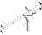
以下、本発明を実施するための形態について図を参照しながら説明する。本発明の締結ブラケット2は、例えば図1に見られるように、デッキクロスメンバ3の運転席側端部31及び助手席側端部32それぞれに溶接により接合され、ステアリング支持フレーム1を構成する。本例のデッキクロスメンバ3は、基本的に断面円形の金属製直管であるが、運転席側が大径、助手席側が小径とした両端異形管であり、大径である運転席側に中間ステー11、コラムブラケット12が取り付けられている。運転席側及び助手席側の締結ブラケット2は、全く同じ仕様である(つまり、左右共通)が、デッキクロスメンバ3が両端異形管であるため、後述するように、各締結ブラケット2に対する運転席側端部31及び助手席側端部32の接合関係が異なる。
Hereinafter, embodiments for carrying out the present invention will be described with reference to the drawings. For example, as shown in FIG. 1, the
本例の締結ブラケット2は、図2〜図5に見られるように、例えばデッキクロスメンバ3の助手席側端部32を接続する本体板21に対し、締結ナット221を固着した接面板22を、前記本体板21と接面板22との接続方向(本例は上下方向)に直交する幅(本例は左右方向の幅)が接面板22以下である接続板23を介して接続し、前記接続板23を除く本体板21と接面板22との間に区画スリット24を形成している。本例の締結ブラケット2は、左右共通の部材であり、運転席側及び助手席側それぞれに鏡面対称の関係(互いが正面を向く関係)でデッキクロスメンバ3の左右両端に接合される。
As shown in FIGS. 2 to 5, the
本体板21は、周縁を正面方向(図2及び中右方向、図4及び図5中図面手前方向)に折り曲げて環状フランジを形成し、全体として剛性を高めた正面視長方形外形の板材で、前記環状フランジに囲まれた平面の範囲で、上下対称に一対の接面板22を設けている。本体板21は、接続板23が弾性変形又は塑性変形する際の基部になる部材で、助手席側の車体フレーム4に接面板22を締結した段階で前記車対フレーム4に対して隙間を残して宙に浮いた状態になる(図9参照)ことから、前記接続板23に対して変形せず、平面が形状を保つ程度の剛性が求められる。このため、本体板21は、本例のように周縁に環状フランジを設けたり、前記環状フランジと別に又は併せて平面内にビードを形成して断面係数を大きくしたりして、剛性を高める。
The
接面板22は、接続板23を構成する中間板231から延びる架橋板233を除いた周囲が区画スリット24に囲まれた正面視正方形状の板材である。本例の本体板21、接面板22及び接続板23(中間板231及び一対の架橋板233)は、連続した一枚の板材から構成されているので、例えばプレス加工に際して区画スリット24及び中間スリット232を打ち抜くことによりそれぞれを一度に形成する。このため、接続板23が弾性変形又は塑性変形しない段階では、本体板21、接面板22及び接続板23が同一平面上に揃っている。接面板22の正面視形状は自由であるが、車体フレーム4に安定して接面するだけの大きさを有することが望まれる。
The
本例の接面板22は、ボルト43の締め付けにより接続板23を弾性変形又は塑性変形させ、車体フレーム4に接面させる(図9参照)際、前記ボルト43の締め付けによる負荷が接続板23に近い位置で加わるように、中心から前記架橋板233に寄った位置に貫通孔222を設け、前記貫通孔222に連通して正面側に締結ナット221を溶接により固着している。貫通孔222を架橋板233に寄った位置に設けた理由は、ボルト43の締め付けによる負荷が接続板23の弾性変形又は組成変形を導きやすくし、対して接続板23が弾性変形又は組成変形しないために接面板22が座屈することを防止するためである。接面板22の座屈を防止するため、接面板22にビードを設けて剛性を高めてもよい。
In the
接続板23は、接面板22の左右方向に延びる辺に平行な長孔状の変形スリット232を相似に囲む中間板231と、本体板21及び接面板22とを、接面板22の左右方向の幅より狭く、区画スリット24の両端に挟まれて括れた一対の架橋板233,233により繋いで構成される。本例の接続板23は、後述するように、同じ締結ブラケット2を用いながらデッキクロスメンバ3の運転席側端部31又は助手席側端部32の接合態様を変え、接面板22の拘束(運転席側端部31)及び非拘束(助手席側端部32)を分けるため、接面板22を挟んでデッキクロスメンバ3の運転席側端部31又は助手席側端部32を接続する本体板21の中心から反対側に設けられている。
The connecting
これにより、助手席側の締結ブラケット2は、図4に見られるように、デッキクロスメンバ3の助手席側端部32が本体板21にのみ接合され、接面板22が車体フレーム4の取付部位に接近離反する方向に架橋板233又は中間板231が弾性変形又は塑性変形して接面板22と前記取付部位との隙間をなくしたり、後述するように、前記取付部位と平行な面方向に架橋板233又は中間板231が弾性変形又は塑性変形して、接面板22に固着した締結ナット221とボルト孔41との位置ズレをなくすことができる。これは、助手席側端部32の強度が、本体板21の剛性にのみ頼っていることを意味する。
As a result, the
これに対し、運転席側の締結ブラケット2は、図5に見られるように、デッキクロスメンバ3の運転手側端部31が本体板21及び接面板22にわたって接合され、上述のような接続板22の弾性変形又は塑性変形が規制され、接面板22が車体フレーム4の取付部位に接近したり、前記取付部位と平行な面方向に変位したりしない。これは、運転席側端部31の強度は、本体板21の剛性のみならず、運転席側端部31を介して結合される本体板21及び接面板22を連結し、互いが相手の変形を抑制することにより向上していることを意味する。こうして、左右共通の締結ブラケット2を用いながら、運転席側の締結ブラケット2の強度を、助手席側の締結ブラケット2の強度に比べて相対的に高くできる。
On the other hand, the
本例の締結ブラケット2は、既述したように、接続板23が弾性変形又は塑性変形することにより、車体フレーム4の取付部位との隙間をなくしたり、締結ナット221とボルト孔41との位置ズレをなくす。従来同種のブラケットも、車体フレーム4の取付部位との隙間をなくすことができたが、本発明の締結ブラケット2は、前記取付部位と平行な面方向に接続板23が弾性変形又は塑性変形して、締結ナット221とボルト孔41との位置ズレをなくすことができる点に特徴を有する。具体的には、図6に見られるように、接続板23は、変形スリット232を広げたり(図6中上の接続板23参照)、潰したりして中間板231を変形させ、接面板22を上下方向に変位させ、また一対の架橋板233の一方又は双方を曲げて(図6中下の接続板23参照)、接面板22を左右方向に変位させることにより、締結ナット221とボルト孔41との位置ズレをなくす。
As described above, the
ステアリング支持フレーム1は、図7に見られるように、車体フレーム4の運転席側では、締結ブラケット2の本体板21、接面板22及び接続板23をすべて取付部位(車体フレーム4を構成する部材の内壁面)に接面させ、圧潰防止のために介装したスペーサ42を通してボルト孔41から左方向に突出させたボルト43を締結ナット221に捩じ込んで、接合する。これから理解されるように、運転席側の締結ブラケット2には弾性変形又は塑性変形する接続板23は不要であり、区画スリット24や接続板23を設けたことが強度低下をもたらしている。そこで、本例は、締結ブラケット2を左右共通に使用しながら、デッキクロスメンバ3の運転席側端部31を本体板21及び接面板22に跨がって溶接することにより、前記区画スリット24や接続板23を設けたことによる強度の低下を防止し、相対的に助手席側の締結ブラケット2との強度差を実現している。
As shown in FIG. 7, the steering support frame 1 is configured such that the
車体フレーム4の取付部位に対する位置ズレは、専ら車体フレーム4の助手席側で調整される。車体フレーム4の運転席側の接合を終えたステアリング支持フレーム1は、図8に見られるように、車体フレーム4の助手席側の取付部位に対し、締結ブラケット2の本体板21、接面板22及び接続板23を同一平面上に揃えた状態で、上下の接面板22それぞれに設けられた各貫通孔222に、スペーサ42を通してボルト孔41から右方向に突出させたボルト43を締結ナット221に螺合させる。この段階で、締結ナット221とボルト孔41とに大きな位置ズレがあれば、接続板23が中間板231を変形させたり、架橋板233を取付部位と平行な面方向に曲げたりして(図6参照)前記位置ズレを解消する。また、締結ナット221とボルト孔41との位置ズレが小さければ、ボルト43を締結ナット221に捩じ込んでいく過程で、接続板23が中間板231を変形させたり、架橋板233を取付部位と平行な面方向に曲げたりして(図6参照)前記位置ズレを解消する。
The positional shift of the
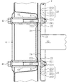
締結ナット221に螺合させたボルト43を捩じ込んでいくと、図9に見られるように、ボルト43は車体フレーム4に頭の移動が規制されているため、相対的に締結ナット221が車体フレーム4に接近するように移動し始め、接面板22を車体フレーム4の取付部位に押し付けることになる。このとき、接面板22は、接続板23の中間板231を変形させたり、架橋板233を接面板22が取付部位に接近離反する方向に曲げたりしながら、取付部位に接近する。このように、取付部位に対する接面板22の接近は、接続板23の弾性変形又は塑性変形による。本体板21は、デッキクロスメンバ3の助手席側端部32が接続されているため、接続板23の弾性変形又は塑性変形の影響を受けることなく、取付部位に対して隙間を残して離れたままになる。この結果、助手席側の締結ブラケット2の強度は、運転席側の締結ブラケット2に比べて相対的に弱くなる。
When the
既述したように、ボルト43を締結ナット221に螺合させた段階で、締結ナット221とボルト孔41とに位置ズレがあっても、接続板23が中間板231を変形させたり、架橋板233を取付部位と平行な面方向に曲げたりして前記位置ズレを解消させるが、締結ナット2に捩じ込むボルト43が傾く虞がある。そこで、図10〜図18に見られるように、車体フレーム4の取付部位に設けられたボルト孔41に嵌まり込むカラー223,225,227を接面板22に設けるとよい。これにより、カラー223,225,227が先行してボルト孔41(正確にはボルト孔41に連通するスペーサ42)に嵌まり込み、取付部位に対して接面板22が平行状態を保ったまま接近し、かつ締結ナット221とボルト孔41とを一致させやすくなる。
As described above, even when the
カラー223は、例えば図10に見られるように、締結ナット221のネジ孔(雌ネジ)に連通する接面板22の貫通孔222を設けるバーリング加工による円筒状フランジにより形成する。バーリング加工は、貫通孔222及びカラー223を同時に形成できる利点がある。本例のカラー223は、先端縁外周を面取りし、ボルト孔41に嵌まり込みやすくしている。カラー223を設けた締結ブラケット2は、取付部位のボルト孔41から突出させたボルト43を締結ナット221に螺合させとき、図11に見られるように、カラー223をボルト孔41に対向させている。そして、ボルト43を締結ナット221に捩じ込んでいくと、カラー223がボルト孔41に嵌まり込んで取付部位に対する接面板22の姿勢や接近方向を規制し、図12に見られるように、接面板22を取付部位に押し付ける。
As shown in FIG. 10, for example, the
バーリング加工によるカラー223に代えて、図13に見られるように、ブッシュ224に設けられた円筒状フランジをカラー225として用い、締結ナット221のネジ孔(雌ネジ)に連通する接面板22の貫通孔222に前記カラー225を嵌合させ、接面板22から突出させてもよい。ブッシュ224は、締結ブラケット2と別部材であるが、締結ナット221と共に予め接面板22に固着される(説明の便宜上、図13中、上段のブッシュ224、締結ナット221を分解して図示している)ため、カラー225の周りに貫通孔222が見える以外、バーリング加工によるカラー223と外観上変わらない(図13中下段参照)。
As shown in FIG. 13, instead of the
本例のカラー225も、先端縁外周を面取りし、ボルト孔41に嵌まり込みやすくしている。カラー225を貫通孔222から突出させた締結ブラケット2は、取付部位のボルト孔41から突出させたボルト43を締結ナット221に螺合させとき、図14に見られるように、カラー225をボルト孔41に対向させ、ボルト43を締結ナット221に捩じ込んでいくと、カラー225がボルト孔41に嵌まり込んで取付部位に対する接面板22の姿勢や接近方向を規制し、図15に見られるように、接面板22を取付部位に押し付ける。ブッシュ224の併用は、部分的に接面板22を肉厚にし、剛性を向上させる利点もある。
The
また、バーリング加工によるカラー223に代えて、図16に見られるように、締結ナット221自体に設けられた円筒状フランジをカラー227として用い、締結ナット221のネジ孔(雌ネジ)に連通する接面板22の貫通孔222に前記カラー227を嵌合させ、接面板22から突出させてもよい。締結ナット221は、予め接面板22に固着される(説明の便宜上、図13中、上段の締結ナット221を分解して図示している)ため、カラー227の周りに貫通孔222が見える以外、バーリング加工によるカラー223と外観上変わらない(図16中下段参照)。カラー227は、締結ナット221の外周に設けた接面フランジ226から突出させ、前記接面フランジ226の外周を接面板22に溶接する。
Further, in place of the
本例のカラー227も、先端縁外周を面取りし、ボルト孔41に嵌まり込みやすくしている。カラー227を貫通孔222から突出させた締結ブラケット2は、取付部位のボルト孔41から突出させたボルト43を締結ナット221に螺合させとき、図17に見られるように、カラー227をボルト孔41に対向させ、ボルト43を締結ナット221に捩じ込んでいくと、カラー227がボルト孔41に嵌まり込んで取付部位に対する接面板22の姿勢や接近方向を規制し、図18に見られるように、接面板22を取付部位に押し付ける。接面フランジ226は、部分的に接面板22を肉厚にし、剛性を向上させる。
The
本例(図1〜図9)以外の接続板25は、例えば図19に見られるように、本体板21に設けた本体スリット251と区画スリット24とに挟まれて形成される変形梁252と、前記変形梁252から延びて接面板22に繋がれる架橋板253とから構成できる。本体板21、接面板22及び接続板25(変形梁252、架橋板253)は、連続した一枚の板材から構成されているので、上述同様、例えばプレス加工に際して区画スリット24及び本体スリット24を打ち抜くことによりそれぞれを一度に形成でき、接続板23が弾性変形又は塑性変形しない段階では本体板21、接面板22及び接続板25が同一平面上に揃っている。
The
本体スリット251は、接続板23による本体板21及び接続板23の接続方向に直交し、架橋板253の左右方向の幅より長く、接続板23を囲む区画スリット24の最大外形幅(左右方向の外周縁の間隔)より短く設けている。これにより、変形梁252は架橋板253より左右方向に長く、また接続板23を囲む区画スリット24の最大外形幅より短くなり、本体板21の構造強度の低下を抑えながら、変形梁252が十分に弾性変形又は塑性変形できる。具体的には、接面板22が車体フレーム4の取付部位に接近離反する方向に架橋板253を弾性変形又は塑性変形させたり、本体スリット251を拡大又は縮小するように変形梁25を上下方向に湾曲するように弾性変形又は塑性変形させたり、そして前記取付部位と平行な面方向に架橋板233又は中間板231を弾性変形又は塑性変形させたりして、接面板22と取付部位との隙間をなくし、接面板22に固着した締結ナット221とボルト孔41との位置ズレをなくす。
The main body slit 251 is orthogonal to the connection direction of the
また、別例の接続板26は、図20に見られるように、左右の幅方向に一様で、厚み方向に屈曲した架橋板261から構成できる。左右の幅方向に一様で、厚み方向に屈曲した架橋板261は、一端が本体板21に、他端が接面板22に繋がれる。本体板21、接面板22及び接続板25(架橋板261)は、連続した一枚の板材から構成されているので、上述同様、例えばプレス加工に際して区画スリット24を打ち抜くことによりそれぞれを一度に形成できる。厚み方向に屈曲した架橋板261は、前記プレス加工と同時に、型に倣って変形させるか、プレス加工による打ち抜き後、別のプレス加工等により変形させる。
In addition, as shown in FIG. 20, the
左右の幅方向に一様で、厚み方向に屈曲した架橋板261から構成される接続板26は、上述までの接続板23(図1〜図9)又は接続板25(図19)と異なり、架橋板261の屈曲断面を弾性変形又は塑性変形させて、接面板22と取付部位との隙間をなくす。このとき、前記架橋板261の左右方向で屈曲断面の変形具合が異なると、接続板26が左右方向に曲がる格好となり、接面板22に固着した締結ナット221とボルト孔41との位置ズレをなくすことができる。この場合、例えば図21に見られるように、厚み方向に屈曲した架橋板271を左右一対設けて接続板27を構成すると、各架橋板271が独立して弾性変形又は塑性変形するので、接続板27を左右方向に曲げやすくなり、接面板22に固着した締結ナット221とボルト孔41との位置ズレを解消しやすくできる。
The
1 ステアリング支持フレーム
2 締結ブラケット
21 本体板
22 接面板
221 締結ナット
222 貫通孔
23 接続板
231 中間板
232 変形スリット
233 一対の架橋板
24 区画スリット
3 デッキクロスメンバ
31 運転席側端部
32 助手席側端部
4 車体フレーム
41 ボルト孔
42 スペーサ
43 ボルト
1
21 Main plate
22 Contact plate
221 Fastening nut
222 Through hole
23 Connection board
231 Intermediate plate
232 Deformation slit
233 Pair of bridge plates
24 division slit 3 deck cross member
31 Driver's side edge
32
41 Bolt hole
42 Spacer
43 bolts
Claims (6)
デッキクロスメンバの端部を接続する本体板に対し、締結ナットを固着した接面板を、前記本体板と接面板との接続方向に直交する幅が接面板以下である接続板を介して接続し、前記接続板を除く本体板と接面板との間に区画スリットを形成し、
接続板は、変形スリットを設けた中間板と、前記中間板より幅が狭く、本体板及び接面板と中間板と繋ぐ一対の架橋板とから構成されることを特徴とするデッキクロスメンバの締結ブラケット。 In the fastening bracket that fastens the left and right ends of the deck cross member to the mounting part of the body frame,
Connect the contact plate to which the fastening nut is fixed to the main body plate connecting the end of the deck cross member via the connection plate whose width perpendicular to the connection direction of the main body plate and the contact plate is equal to or less than the contact plate. , Forming a partition slit between the body plate and the contact plate excluding the connection plate ,
Fastening of the deck cross member characterized in that the connection plate is composed of an intermediate plate provided with a deformation slit and a pair of bridge plates that are narrower than the intermediate plate and connect to the main body plate, the contact surface plate and the intermediate plate. bracket.
Priority Applications (2)
| Application Number | Priority Date | Filing Date | Title |
|---|---|---|---|
| JP2010094821A JP5599218B2 (en) | 2010-04-16 | 2010-04-16 | Deck cross member fastening bracket |
| US13/088,952 US8302918B2 (en) | 2010-04-16 | 2011-04-18 | Fastening bracket of deck cross member |
Applications Claiming Priority (1)
| Application Number | Priority Date | Filing Date | Title |
|---|---|---|---|
| JP2010094821A JP5599218B2 (en) | 2010-04-16 | 2010-04-16 | Deck cross member fastening bracket |
Publications (3)
| Publication Number | Publication Date |
|---|---|
| JP2010215231A JP2010215231A (en) | 2010-09-30 |
| JP2010215231A5 JP2010215231A5 (en) | 2013-05-23 |
| JP5599218B2 true JP5599218B2 (en) | 2014-10-01 |
Family
ID=42974508
Family Applications (1)
| Application Number | Title | Priority Date | Filing Date |
|---|---|---|---|
| JP2010094821A Expired - Fee Related JP5599218B2 (en) | 2010-04-16 | 2010-04-16 | Deck cross member fastening bracket |
Country Status (2)
| Country | Link |
|---|---|
| US (1) | US8302918B2 (en) |
| JP (1) | JP5599218B2 (en) |
Families Citing this family (3)
| Publication number | Priority date | Publication date | Assignee | Title |
|---|---|---|---|---|
| DE102016118138B4 (en) * | 2016-09-26 | 2020-04-16 | Benteler Automobiltechnik Gmbh | Tolerance compensation element for compensating a distance between an instrument carrier and a body component of a vehicle |
| CN106545177B (en) * | 2016-11-17 | 2019-02-19 | 山东普瑞玛模板有限公司 | A kind of quick-locking device applied to connection pillar |
| US11148213B2 (en) * | 2019-01-03 | 2021-10-19 | Kennametal Inc. | Hardware fastener with movable threaded element and one or more spring-like members |
Family Cites Families (7)
| Publication number | Priority date | Publication date | Assignee | Title |
|---|---|---|---|---|
| JP3778762B2 (en) | 2000-03-10 | 2006-05-24 | ダイハツ工業株式会社 | Vehicle frame connection structure |
| JP2002029452A (en) * | 2000-07-19 | 2002-01-29 | Denso Corp | Mounting structure for vehicular beam member |
| JP2006199050A (en) * | 2005-01-17 | 2006-08-03 | Unipres Corp | Attachment structure for steering member |
| JP4119919B2 (en) * | 2006-01-27 | 2008-07-16 | 株式会社アステア | Steering column bracket |
| JP5244565B2 (en) * | 2008-12-01 | 2013-07-24 | カルソニックカンセイ株式会社 | Body strength member structure |
| JP5533436B2 (en) * | 2010-08-25 | 2014-06-25 | スズキ株式会社 | Steering support member structure |
| US8646626B2 (en) * | 2010-12-31 | 2014-02-11 | Globe Union Industrial Corp. | Wall mounting bath accessory assembly |
-
2010
- 2010-04-16 JP JP2010094821A patent/JP5599218B2/en not_active Expired - Fee Related
-
2011
- 2011-04-18 US US13/088,952 patent/US8302918B2/en not_active Expired - Fee Related
Also Published As
| Publication number | Publication date |
|---|---|
| US8302918B2 (en) | 2012-11-06 |
| US20110253857A1 (en) | 2011-10-20 |
| JP2010215231A (en) | 2010-09-30 |
Similar Documents
| Publication | Publication Date | Title |
|---|---|---|
| JP5508109B2 (en) | Steering support frame | |
| US6702324B2 (en) | Knee bolster | |
| JP6278030B2 (en) | Vehicle front structure | |
| JP2015168364A (en) | Front structure of vehicle body | |
| WO2014167638A1 (en) | Vehicle seat and seat frame for same | |
| JP5599218B2 (en) | Deck cross member fastening bracket | |
| CN107972646B (en) | Brake pedal apparatus for vehicle | |
| US9802637B2 (en) | Steering device | |
| US7699285B2 (en) | Automotive mirror mounting system | |
| JPH09272448A (en) | Shock absorbing type steering column device | |
| JP2016037084A (en) | Fitting structure of instrument panel reinforcement | |
| JP2001260902A (en) | Energy absorbing steering device | |
| WO2018181082A1 (en) | Steering device | |
| JP2017154558A (en) | Steering device | |
| KR101885022B1 (en) | Steering Column for Vehicle | |
| JPH0891154A (en) | Bumper stay | |
| JP2020029219A (en) | Mirror fitting structure | |
| JP4687365B2 (en) | Vehicle door structure | |
| KR20130109584A (en) | A bumper beam unit for vehicles | |
| JP6299118B2 (en) | Side door | |
| KR102200172B1 (en) | Cross member for car | |
| JP4835988B2 (en) | Mounting bracket | |
| JP4192010B2 (en) | Tilt steering column support device | |
| JP2000168616A (en) | Body cross member | |
| JP2017105331A (en) | Airbag device |
Legal Events
| Date | Code | Title | Description |
|---|---|---|---|
| A521 | Written amendment |
Free format text: JAPANESE INTERMEDIATE CODE: A821 Effective date: 20100707 |
|
| A521 | Written amendment |
Free format text: JAPANESE INTERMEDIATE CODE: A523 Effective date: 20130404 |
|
| A621 | Written request for application examination |
Free format text: JAPANESE INTERMEDIATE CODE: A621 Effective date: 20130404 |
|
| A977 | Report on retrieval |
Free format text: JAPANESE INTERMEDIATE CODE: A971007 Effective date: 20140217 |
|
| A131 | Notification of reasons for refusal |
Free format text: JAPANESE INTERMEDIATE CODE: A131 Effective date: 20140225 |
|
| A521 | Written amendment |
Free format text: JAPANESE INTERMEDIATE CODE: A523 Effective date: 20140416 |
|
| TRDD | Decision of grant or rejection written | ||
| A01 | Written decision to grant a patent or to grant a registration (utility model) |
Free format text: JAPANESE INTERMEDIATE CODE: A01 Effective date: 20140729 |
|
| A61 | First payment of annual fees (during grant procedure) |
Free format text: JAPANESE INTERMEDIATE CODE: A61 Effective date: 20140812 |
|
| R150 | Certificate of patent or registration of utility model |
Ref document number: 5599218 Country of ref document: JP Free format text: JAPANESE INTERMEDIATE CODE: R150 |
|
| R250 | Receipt of annual fees |
Free format text: JAPANESE INTERMEDIATE CODE: R250 |
|
| R250 | Receipt of annual fees |
Free format text: JAPANESE INTERMEDIATE CODE: R250 |
|
| LAPS | Cancellation because of no payment of annual fees |