JP5598065B2 - Sealing structure - Google Patents
Sealing structure Download PDFInfo
- Publication number
- JP5598065B2 JP5598065B2 JP2010092289A JP2010092289A JP5598065B2 JP 5598065 B2 JP5598065 B2 JP 5598065B2 JP 2010092289 A JP2010092289 A JP 2010092289A JP 2010092289 A JP2010092289 A JP 2010092289A JP 5598065 B2 JP5598065 B2 JP 5598065B2
- Authority
- JP
- Japan
- Prior art keywords
- gasket
- reinforcing ring
- annular groove
- members
- annular
- Prior art date
- Legal status (The legal status is an assumption and is not a legal conclusion. Google has not performed a legal analysis and makes no representation as to the accuracy of the status listed.)
- Active
Links
Images


Description
本発明は、ガスケットを備えた密封構造に関するものである。 The present invention relates to a sealing structure provided with a gasket.
従来、2部材のうちの一方の部材に設けられた環状溝に装着され、これら2部材の対向面間の隙間を封止する環状のガスケットが知られている。例えば、自動車に備えられたインテークマニホールドとシリンダーブロックとの対向面間の隙間を封止するために環状のガスケットが用いられる。 Conventionally, an annular gasket that is mounted in an annular groove provided in one of two members and seals a gap between opposing surfaces of these two members is known. For example, an annular gasket is used to seal a gap between opposed surfaces of an intake manifold and a cylinder block provided in an automobile.
かかるガスケットは、2部材により圧縮されることで、その反発力によってシール性を発揮する。ここで、2部材のうちの少なくとも一方が樹脂材で構成されるような場合には、成形時のうねりやクリープ等の影響で、寸法精度がそれほど高くない場合がある。そのため、寸法がばらついているような場合でもシール性能を発揮できる必要がある。また、スペースの関係上、ガスケットが装着される環状溝の断面形状が縦長断面となる場合がある。以上のような場合には、ガスケットの断面も縦長断面としなければならず、環状溝内において、ガスケットの倒れや座屈が発生し易いという問題がある。このような問題の対策として、従来、ガスケットの外周側と内周側に、ガスケットの倒れを抑制するための突起を、周方向に各々間隔を空けて複数設ける技術が知られている。 Such a gasket is compressed by two members, and exhibits a sealing property by its repulsive force. Here, when at least one of the two members is made of a resin material, the dimensional accuracy may not be so high due to the influence of waviness or creep during molding. Therefore, it is necessary to be able to exhibit the sealing performance even when the dimensions vary. In addition, because of the space, the cross-sectional shape of the annular groove in which the gasket is mounted may be a vertically long cross section. In such a case, the cross section of the gasket must also be a vertically long cross section, and there is a problem that the gasket is liable to collapse or buckle in the annular groove. As a countermeasure against such a problem, a technique is conventionally known in which a plurality of protrusions for suppressing the collapse of the gasket are provided on the outer peripheral side and the inner peripheral side of the gasket at intervals in the circumferential direction.
このように構成された従来例に係るガスケットについて図8を参照して説明する。図8は従来例に係るガスケットの装着時の様子を示す模式的断面図である。なお、この従来例に係るガスケット500は、インテークマニホールド200に設けられた環状溝201に装着されて、インテークマニホールド200とシリンダーブロック300との対向面間の隙間を封止するために用いられる。
A conventional gasket having such a configuration will be described with reference to FIG. FIG. 8 is a schematic cross-sectional view showing a state when the gasket according to the conventional example is mounted. The
図示のように、ガスケット500は、断面が縦長形状のガスケット本体部510と、環状溝201の溝底面に密着する第1シール突起部511と、シリンダーブロック300の取付面301に密着する第2シール突起部512とを備えている。また、ガスケット本体部510の外周側と内周側には、環状溝201内においてガスケット本体部510が倒れることを抑制する突起521,522が、周方向に各々間隔を空けて複数設けられている。なお、図8はこれらの突起521,522が設けられている部分において、ガスケット500の長手方向に対して垂直な方向に切断した断面図である。
As shown in the drawing, the
ここで、一般的に、インテークマニホールド200とシリンダーブロック300は、これらの対向面に垂直な方向(図8中、矢印X方向)に組み付けられる。これに伴い、上記のように構成されたガスケット500は、図示の断面において幅方向(左右方向)の中心に対して略対称的な状態を保ったまま圧縮する。これにより、第1シール突起部511が環状溝201の溝底面に密着し、かつ第2シール突起部512がシリンダーブロック300の取付面301に密着することでシール性能が発揮される。また、ガスケット本体部510は縦長断面で構成されており、本来的には環状溝201内で倒れたり座屈したりし易いものの、ガスケット500の圧縮に伴い突起521,522が環状溝201の両側面にそれぞれ突き当たることで、倒れや座屈が抑制される。
Here, in general,
しかしながら、インテークマニホールド200とシリンダーブロック300が、これらの対向面に垂直な方向に対して傾いた方向に組み付けられるように構成される場合がある。例えば、図8中の矢印Y方向に組み付けられる場合がある。この場合、ガスケット500における第2シール突起部512には、前記対向面に垂直な方向に対して傾いた方向に
力が加わるため、第2シール突起部512は倒れるように変形してしまう。そのため、ガスケット500は、図示の断面において幅方向(左右方向)の中心に対して略対称的な状態を保ったまま圧縮することができず、当該中心に対して非対称的な状態で圧縮してしまう。また、ガスケット500は環状であることから、第2シール突起部512に加えられる力の方向は、力が与えられる部位によって異なるため、変形の仕方も部位により異なる。従って、シール性能が不安定になってしまう。
However, the
また、第2シール突起部512の変形の仕方によっては、図9に示すように、第2シール突起部512の先端付近Zが、インテークマニホールド200における環状溝201の開口端縁付近と、シリンダーブロック300の取付面301との間に噛み込まれてしまうことも考えられる。この場合には、先端付近Zに亀裂が生じたり、欠けが生じたりして、シール機能が損なわれてしまうおそれがある。
Further, depending on how the
本発明の目的は、装着溝内におけるガスケットの倒れを抑制する密封構造を提供することにある。 The objective of this invention is providing the sealing structure which suppresses the fall of the gasket in a mounting groove.
本発明は、上記課題を解決するために以下の手段を採用した。 The present invention employs the following means in order to solve the above problems.
すなわち、本発明の密封構造は、
互いに組み付けられる2部材と、
これら2部材のうちの一方の部材に設けられる環状溝と、
前記環状溝に装着され、前記2部材の対向面間の隙間を封止する環状のガスケットと、を備え、
前記2部材は前記対向面に垂直な方向に対して傾いた方向に組み付けられ、これら2部材により前記ガスケットが圧縮されるように構成された密封構造であって、
前記ガスケットは、
環状の補強環と、
該補強環に一体的に設けられ、かつその断面形状が前記環状溝への装着方向の長さの方が幅方向の長さよりも長い縦長のゴム状弾性体製のガスケット本体と、を備えており、
前記環状溝には、前記補強環が突き当たることで、該補強環の傾きを制限する位置規制部が設けられていることを特徴とする。
That is, the sealing structure of the present invention is
Two members assembled together;
An annular groove provided in one of these two members;
An annular gasket mounted in the annular groove and sealing a gap between the opposing surfaces of the two members,
The two members are assembled in a direction inclined with respect to a direction perpendicular to the facing surface, and the gasket is configured to be compressed by the two members,
The gasket is
An annular reinforcing ring,
A gasket main body made of a vertically long rubber-like elastic body that is provided integrally with the reinforcing ring and whose cross-sectional shape is longer in the mounting direction in the annular groove than in the width direction. And
The annular groove is provided with a position restricting portion that restricts the inclination of the reinforcing ring by abutting the reinforcing ring.
本発明によれば、補強環によってガスケット本体の変形が抑制され、かつ環状溝に設けられた位置規制部によって補強環の傾きが制限されるので、環状溝内におけるガスケットの倒れが抑制される。また、これに伴い、ガスケット本体の先端が、環状溝の外側に飛び出してしまうことも抑制できる。これらのことから、安定したシール性能が発揮される。 According to the present invention, the deformation of the gasket main body is suppressed by the reinforcing ring, and the inclination of the reinforcing ring is limited by the position restricting portion provided in the annular groove, so that the fall of the gasket in the annular groove is suppressed. Further, along with this, it is possible to suppress the tip of the gasket body from jumping out of the annular groove. From these things, the stable sealing performance is exhibited.
ここで、前記補強環は中心に孔の空いた円板状の部材で構成されており、
前記環状溝における側面側の周面と、前記補強環の側面側の周面との間に隙間を有した状態で、前記ガスケットが前記環状溝に装着されるように構成されており、
前記ガスケットが前記環状溝に対して傾くと、前記補強環の前記周面における端縁の少なくとも一部が前記環状溝における前記周面に突き当たることで、前記補強環の傾きが制
限されるとよい。
Here, the reinforcing ring is composed of a disk-shaped member having a hole in the center,
The gasket is configured to be attached to the annular groove with a gap between the peripheral surface on the side surface side of the annular groove and the peripheral surface on the side surface side of the reinforcing ring,
When the gasket is tilted with respect to the annular groove, at least a part of an edge of the circumferential surface of the reinforcing ring abuts against the circumferential surface of the annular groove, so that the inclination of the reinforcing ring is limited. .
これにより、簡易的な構成で、補強環の傾きを制限できる。 Thereby, the inclination of a reinforcement ring can be restrict | limited with a simple structure.
また、前記補強環は、
中心に孔が空き、かつその一部が前記ガスケット本体の内部に埋め込まれた状態にある円板部と、
該円板部の端部から折れ曲がった円筒部と、を備えており、
前記環状溝は、前記円筒部の先端側が遊びを持った状態で嵌合される遊嵌溝を備えていることも好適である。
The reinforcing ring is
A disc having a hole in the center and a part of which is embedded in the gasket body;
A cylindrical portion bent from an end of the disc portion, and
It is also preferable that the annular groove includes a loose fitting groove that is fitted in a state in which the tip side of the cylindrical portion has play.
これにより、補強環の傾きをより確実に制限できる。 Thereby, the inclination of a reinforcement ring can be restrict | limited more reliably.
以上説明したように、本発明によれば、装着溝内においてガスケットの倒れを抑制でき、安定した密封性能を維持することができる。 As described above, according to the present invention, the gasket can be prevented from falling in the mounting groove, and a stable sealing performance can be maintained.
以下に図面を参照して、この発明を実施するための形態を、実施例に基づいて例示的に詳しく説明する。ただし、この実施例に記載されている構成部品の寸法、材質、形状、その相対配置などは、特に特定的な記載がない限りは、この発明の範囲をそれらのみに限定する趣旨のものではない。 DESCRIPTION OF EMBODIMENTS Hereinafter, embodiments for carrying out the present invention will be exemplarily described in detail with reference to the drawings. However, the dimensions, materials, shapes, relative arrangements, and the like of the components described in this embodiment are not intended to limit the scope of the present invention only to those unless otherwise specified. .
(実施例1)
図1〜図4を参照して、本発明の実施例1に係る密封構造について説明する。なお、本実施例においては、密封構造を構成する2部材が、インテークマニホールドとシリンダーブロックである場合を例にして説明する。
Example 1
With reference to FIGS. 1-4, the sealing structure which concerns on Example 1 of this invention is demonstrated. In the present embodiment, the case where the two members constituting the sealing structure are an intake manifold and a cylinder block will be described as an example.
<密封構造>
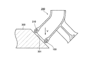
特に、図1を参照して、本発明の実施例1に係る密封構造全体の構成について説明する。図1は本発明の実施例1に係る密封構造の模式的断面図である。インテークマニホールド200とシリンダーブロック300は、図1中の矢印V方向に組み付けられるように構
成されている。ここで、これらの組み付け方向Vは、図1から明らかなように、これらの対向面に垂直な方向に対して傾いた方向である。
<Sealing structure>
In particular, with reference to FIG. 1, the configuration of the entire sealing structure according to the first embodiment of the present invention will be described. FIG. 1 is a schematic cross-sectional view of a sealing structure according to Embodiment 1 of the present invention.
また、インテークマニホールド200におけるシリンダーブロック300との対向面側には環状溝210が設けられている。この環状溝210に、ガスケット100が装着される。このガスケット100は、インテークマニホールド200とシリンダーブロック300との対向面間の隙間を封止するために用いられる。なお、図1においては、ガスケット100と環状溝210の構成は簡易的に示している。
An
本実施例に係るインテークマニホールド200は、V型構造であり、吸気管がV字状に分岐する構成となっている。これに伴い、吸気管の先端が突き当たるシリンダーブロック300の取付面301は傾斜面によって構成されている。
The
<ガスケット>
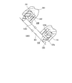
特に、図2〜図4を参照して、ガスケット100と、ガスケット100の倒れを抑制する構造について説明する。なお、図2はガスケット100の平面図であり、図3,4は密封構造の模式的拡大断面図である。図3,4におけるガスケットは図2中のAA断面に相当する。また、図3はインテークマニホールド200とシリンダーブロック300を組み付ける前の状態を示し、図4はこれらを組み付けた後の状態を示している。
<Gasket>
In particular, with reference to FIG. 2 to FIG. 4, the
ガスケット100は、金属製の補強環120と、補強環120の内周端側に一体的に設けられたゴム状弾性体製のガスケット本体110とから構成される。このガスケット100は、補強環120をインサート部品として、インサート成形によって製造することができる。
The
補強環120は、中心に孔の空いた円板状の部材で構成されている。補強環120の材質としては、鉄系、アルミニウム系、ステンレス系などの各種金属や、硬質の樹脂材を適用できる。
The reinforcing
ガスケット本体110は、円環状の部材で構成されている。また、ガスケット本体110の断面形状(円周方向に対して垂直な断面の形状)は、環状溝210への装着方向の長さの方が幅方向よりも長い縦長形状となっている。そして、この縦長の両端のシール突起部が、インテークマニホールド200とシリンダーブロック300にそれぞれ密着するように構成されている。また、上記の両端のシール突起部は、先細り形状となるように構成されている。
The
環状溝210は、ガスケット本体110が装着される深溝部211と、補強環120が入り込む浅溝部212とを備える段付き溝である。そして、浅溝部212における内周面212aの内径は、補強環120の外径よりも僅かに大きく設定されている。これにより、ガスケット100が環状溝210に装着される場合には、環状溝210における内周面212aと、補強環120の外周面との間に微小隙間を有した状態で、ガスケット100が環状溝210に装着される。これにより、ガスケット100を簡単に環状溝210に装着することができる。なお、ガスケット本体110のつぶし代を確保するために、浅溝部212の溝底部分と補強環120との間には、図3に示すように、適度な隙間が設けられる。
The
また、ガスケット100が環状溝210に対して傾くと、補強環120の外周面における端縁の少なくとも一部が環状溝210の内周面212aに突き当たることで、補強環120の傾きは制限されるように構成されている。これにより、環状溝210内でのガスケット100の倒れが抑制される。なお、環状溝210における内周面212aは、補強環
120の傾きを制限する位置規制部として機能している。
Further, when the
<本実施例に係る密封構造の優れた点>
本実施例に係る密封構造によれば、インテークマニホールド200とシリンダーブロック300を図3中矢印V方向に組み付ける過程で、ガスケット本体110の先端がシリンダーブロック300の取付面301からの力を受ける。この力を受ける方向は、ガスケット本体110の圧縮方向に対して傾いている。そのため、ガスケット100には、環状溝210内において、図4中矢印M方向に回転する方向に力が作用する。
<Excellent point of sealing structure according to this embodiment>
According to the sealing structure of the present embodiment, the tip of the
しかしながら、上記の通り、本実施例に係るガスケット100は、補強環120を備えており、補強環120自体は殆ど変形しないため、ガスケット本体110の変形も抑制される。また、補強環120の外周面における端縁の少なくとも一部が環状溝210の内周面212aに突き当たることで、補強環120の傾きは制限される。すなわち、図4に示すように、補強環120における上方側において、外周面における下側の端縁が環状溝210の内周面212aに突き当たる。また、補強環120における下方側において、外周面における上側の端縁が環状溝210の内周面212aに突き当たる。これにより、補強環120の傾きが制限されて、環状溝210内におけるガスケット100の傾き(倒れ)が抑制される。
However, as described above, the
これらのことから、環状溝210内におけるガスケット100の姿勢を安定させることができる。また、これに伴い、ガスケット本体110の先端のシール突起部が、環状溝210の外側に飛び出してしまうことも抑制できる。なお、本実施例においては、当該シール突起部を先細り形状としたことによって、環状溝210の外側への飛び出しを、より抑制できるようにしている。ここで、環状溝210における内周端縁(深溝部211の内周端縁)にC面やR面などの面取りを設けることによって、シール突起部の環状溝210の外側への飛び出しを、より抑制できるようにしてもよい。
From these things, the attitude | position of the
(実施例2)
図5には、本発明の実施例2が示されている。上記実施例1では、ガスケットを、補強環と、補強環の内周端側に一体的に設けられたガスケット本体とから構成される場合を示した。これに対し、本実施例においては、ガスケットを、補強環と、補強環の外周端側に一体的に設けられたガスケット本体とから構成される場合を示す。
(Example 2)
FIG. 5 shows a second embodiment of the present invention. In the said Example 1, the case where a gasket was comprised from the reinforcement ring and the gasket main body integrally provided in the inner peripheral end side of the reinforcement ring was shown. On the other hand, in the present embodiment, a case is shown in which the gasket is composed of a reinforcing ring and a gasket body integrally provided on the outer peripheral end side of the reinforcing ring.
その他の構成および作用については実施例1と同一なので、同一の構成部分については同一の符号を付して、その説明は省略する。 Since other configurations and operations are the same as those in the first embodiment, the same components are denoted by the same reference numerals and description thereof is omitted.
本実施例に係るガスケット101は、金属製の補強環121と、補強環121の外周端側に一体的に設けられたゴム状弾性体製のガスケット本体111とから構成される。
The
ガスケット101の製造方法、補強環121の形状や材料の例、ガスケット本体111の形状等については、補強環121とガスケット本体111との位置関係が異なること以外は、上記実施例1と同様であるので、その説明は省略する。
The manufacturing method of the
環状溝220は、ガスケット本体111が装着される深溝部221と、補強環121が入り込む浅溝部222とを備える段付き溝である。そして、浅溝部222における外周面222aの外径は、補強環121の内径よりも僅かに小さく設定されている。これにより、ガスケット101が環状溝220に装着される場合には、環状溝220における外周面222aと、補強環121の内周面との間に微小隙間を有した状態で、ガスケット101が環状溝220に装着される。これにより、ガスケット101を簡単に環状溝220に装着することができる。なお、ガスケット本体111のつぶし代を確保するために、浅溝部
222の溝底部分と補強環121との間には、図5に示すように、適度な隙間が設けられる。
The
また、ガスケット101が環状溝220に対して傾くと、補強環121の内周面における端縁の少なくとも一部が環状溝220の外周面222aに突き当たることで、補強環121の傾きは制限されるように構成されている。これにより、環状溝220内でのガスケット101の倒れが抑制される。なお、環状溝220における外周面222aは、補強環121の傾きを制限する位置規制部として機能している。なお、インテークマニホールド200とシリンダーブロック300を図5中矢印V方向に組み付ける過程で、ガスケット101には、環状溝220内において、図5中矢印M方向に回転する方向に力が作用する。
Further, when the
以上の構成により、本実施例に係る密封構造においても、上記実施例1の場合と同様の効果を得ることができる。また、本実施例においても、環状溝220における外周端縁(深溝部221の外周端縁)にC面やR面などの面取りを設けることによって、シール突起部の環状溝220の外側への飛び出しを、より抑制できるようにしてもよい。
With the above configuration, even in the sealing structure according to the present embodiment, the same effect as that of the first embodiment can be obtained. Also in this embodiment, by providing a chamfer such as a C surface or an R surface at the outer peripheral edge of the annular groove 220 (the outer peripheral edge of the deep groove portion 221), the seal protrusion protrudes outside the
(実施例3)
図6には、本発明の実施例3が示されている。上記実施例1,2では、中心に孔の空いた円板状の部材で構成された補強環を用い、この補強環の周面(実施例1では外周面、実施例2では内周面)における端縁の少なくとも一部が環状溝の周面(実施例1では内周面、実施例2では外周面)に突き当たることで、補強環の傾きを制限させる場合を示した。これに対し、本実施例においては、中心に孔の空いた円板部と、円板部の端部から折れ曲がった円筒部とを備える補強環を用い、円筒部が遊嵌溝に遊嵌する(遊びを持った状態で嵌合する)ことで補強環の傾きを制限させる場合の構成を示す。
(Example 3)
FIG. 6 shows a third embodiment of the present invention. In the said Example 1, 2, the reinforcement ring comprised by the disk-shaped member with a hole in the center was used, and the peripheral surface of this reinforcement ring (in Example 1, an outer peripheral surface, in Example 2, an internal peripheral surface) The case where the inclination of the reinforcing ring is limited by at least a part of the edge of the ring abutting against the circumferential surface of the annular groove (the inner circumferential surface in Example 1 and the outer circumferential surface in Example 2) is shown. On the other hand, in the present embodiment, a reinforcing ring including a disc portion having a hole in the center and a cylindrical portion bent from an end portion of the disc portion is used, and the cylindrical portion is loosely fitted in the loose fitting groove. A configuration in the case where the inclination of the reinforcing ring is limited by (fitting with play) is shown.
その他の構成および作用については実施例1と同一なので、同一の構成部分については同一の符号を付して、その説明は省略する。 Since other configurations and operations are the same as those in the first embodiment, the same components are denoted by the same reference numerals and description thereof is omitted.
本実施例に係るガスケット102は、金属製の補強環122と、補強環122の内周端側に一体的に設けられたゴム状弾性体製のガスケット本体112とから構成される。このガスケット102は、補強環122をインサート部品として、インサート成形によって製造することができる。
The
補強環122は、中心に孔が空き、かつその一部(内周端部)がガスケット本体112の内部に埋め込まれた状態にある円板部122aと、円板部122aの外周端部から折れ曲がった円筒部122bと、から構成されている。補強環122の材質としては、鉄系、アルミニウム系、ステンレス系などの各種金属や、硬質の樹脂材を適用できる。
The reinforcing
ガスケット本体112は、円環状の部材で構成されている。また、ガスケット本体112の断面形状(円周方向に対して垂直な断面の形状)は、環状溝230への装着方向の長さの方が幅方向よりも長い縦長形状となっている。そして、この縦長の両端のシール突起部が、インテークマニホールド200とシリンダーブロック300にそれぞれ密着するように構成されている。また、上記の両端のシール突起部は、先細り形状となるように構成されている。
The
また、本実施例に係る環状溝230は、ガスケット本体112が装着される装着溝部231と、補強環122における円筒部122bの先端側が遊びを持った状態で嵌合される遊嵌溝部232とを備えている。このように、本実施例においては、ガスケット102が環状溝230に装着される場合には、補強環122における円筒部122bが遊びを持っ
た状態で、遊嵌溝部232に嵌合されるので、ガスケット102を簡単に環状溝230に装着することができる。なお、ガスケット本体112のつぶし代を確保するために、遊嵌溝部232の溝底部分と補強環122における円筒部122bの先端との間には、図6に示すように、適度な隙間が設けられる。
Further, the
また、ガスケット102が環状溝230に対して傾くと、補強環122における円筒部122bが遊嵌溝部232の内周面や外周面に突き当たることで、補強環122の傾きは制限されるように構成されている。つまり、補強環122は、遊嵌溝部232に対する円筒部122bの遊び分だけしかがたつかない。これにより、環状溝230内でのガスケット102の倒れが抑制される。なお、遊嵌溝部232の内周面及び外周面は、補強環122の傾きを制限する位置規制部として機能している。
Further, when the
以上の構成により、本実施例に係る密封構造においても、上記実施例1,2の場合と同様の効果を得ることができる。なお、本実施例の場合の方が、遊びの調整によって、補強環122の傾きを簡単に制限できるので、実施例1,2に比べて、補強環122の傾きをより確実に抑制し易い。また、本実施例においても、環状溝230における内周端縁(装着溝部231の内周端縁)にC面やR面などの面取りを設けることによって、シール突起部の環状溝230の外側への飛び出しを、より抑制できるようにしてもよい。
With the above configuration, the same effects as those of the first and second embodiments can be obtained in the sealing structure according to the present embodiment. In the case of the present embodiment, since the inclination of the reinforcing
(実施例4)
図7には、本発明の実施例4が示されている。上記実施例3では、ガスケット本体を、補強環の内周端側に一体的に設ける場合の構成を示した。これに対し、本実施例においては、ガスケット本体を補強環の外周端側に一体的に設ける場合の構成を示す。
Example 4
FIG. 7 shows a fourth embodiment of the present invention. In the said Example 3, the structure in the case of providing a gasket main body integrally in the inner peripheral end side of a reinforcement ring was shown. On the other hand, in a present Example, the structure in the case of providing a gasket main body integrally in the outer peripheral end side of a reinforcement ring is shown.
その他の構成および作用については実施例3と同一なので、同一の構成部分については同一の符号を付して、その説明は省略する。 Since other configurations and operations are the same as those of the third embodiment, the same components are denoted by the same reference numerals and description thereof is omitted.
本実施例に係るガスケット103は、金属製の補強環123と、補強環123の外周端側に一体的に設けられたゴム状弾性体製のガスケット本体113とから構成される。
The
補強環123は、中心に孔が空き、かつその一部(外周端部)がガスケット本体113の内部に埋め込まれた状態にある円板部123aと、円板部123aの内周端部から折れ曲がった円筒部123bと、から構成されている。
The reinforcing
ガスケット103の製造方法、補強環の材料の例、ガスケット本体113の形状等については、補強環123とガスケット本体113との位置関係が異なること以外は、上記実施例3と同様であるので、その説明は省略する。
The manufacturing method of the
また、本実施例に係る環状溝240は、ガスケット本体113が装着される装着溝部241と、補強環123における円筒部123bの先端側が遊びを持った状態で嵌合される遊嵌溝部242とを備えている。このように、本実施例においては、ガスケット103が環状溝240に装着される場合には、補強環123における円筒部123bが遊びを持った状態で、遊嵌溝部242に嵌合されるので、ガスケット103を簡単に環状溝240に装着することができる。なお、ガスケット本体113のつぶし代を確保するために、遊嵌溝部242の溝底部分と補強環123における円筒部123bの先端との間には、図7に示すように、適度な隙間が設けられる。
Further, the
以上のような構成により、本実施例の場合においても、補強環123は、遊嵌溝部242に対する円筒部123bの遊び分だけしかがたつかない。従って、上記実施例3の場合と同様の効果を得ることができる。また、本実施例においても、環状溝240における外
周端縁(装着溝部241の外周端縁)にC面やR面などの面取りを設けることによって、シール突起部の環状溝240の外側への飛び出しを、より抑制できるようにしてもよい。
With the configuration as described above, even in the case of the present embodiment, the reinforcing
100,101,102,103 ガスケット
110,111,112,113 ガスケット本体
120,121,122,123 補強環
122a,123a 円板部
122b,123b 円筒部
200 インテークマニホールド
210,220,230,240 環状溝
211,221 深溝部
212,222 浅溝部
212a 内周面
222a 外周面
231,241 装着溝部
232,242 遊嵌溝部
300 シリンダーブロック
301 取付面
100, 101, 102, 103
Claims (2)
これら2部材のうちの一方の部材に設けられる環状溝と、
前記環状溝に装着され、前記2部材の対向面間の隙間を封止する環状のガスケットと、を備え、
前記2部材は前記対向面に垂直な方向に対して傾いた方向に組み付けられ、これら2部材により前記ガスケットが圧縮されるように構成された密封構造であって、
前記ガスケットは、
環状の補強環と、
該補強環に一体的に設けられ、かつその断面形状が前記環状溝への装着方向の長さの方が幅方向の長さよりも長い縦長のゴム状弾性体製のガスケット本体と、を備えており、
前記環状溝には、前記補強環が突き当たることで、該補強環の傾きを制限する位置規制部が設けられていると共に、
前記補強環は中心に孔の空いた円板状の部材で構成されており、
前記環状溝における側面側の周面と、前記補強環の側面側の周面との間に隙間を有した状態で、前記ガスケットが前記環状溝に装着されるように構成されており、
前記ガスケットが前記環状溝に対して傾くと、前記補強環の前記周面における端縁の少なくとも一部が前記環状溝における前記周面に突き当たることで、前記補強環の傾きが制限されることを特徴とする密封構造。 Two members assembled together;
An annular groove provided in one of these two members;
An annular gasket mounted in the annular groove and sealing a gap between the opposing surfaces of the two members,
The two members are assembled in a direction inclined with respect to a direction perpendicular to the facing surface, and the gasket is configured to be compressed by the two members,
The gasket is
An annular reinforcing ring,
A gasket main body made of a vertically long rubber-like elastic body that is provided integrally with the reinforcing ring and whose cross-sectional shape is longer in the mounting direction in the annular groove than in the width direction. And
The annular groove is provided with a position restricting portion that restricts the inclination of the reinforcing ring by striking the reinforcing ring ,
The reinforcing ring is composed of a disk-shaped member having a hole in the center,
The gasket is configured to be attached to the annular groove with a gap between the peripheral surface on the side surface side of the annular groove and the peripheral surface on the side surface side of the reinforcing ring,
When the gasket is inclined with respect to the annular groove, at least a part of the edge of the peripheral surface of the reinforcing ring abuts on the peripheral surface of the annular groove, thereby limiting the inclination of the reinforcing ring. Characteristic sealing structure.
これら2部材のうちの一方の部材に設けられる環状溝と、
前記環状溝に装着され、前記2部材の対向面間の隙間を封止する環状のガスケットと、を備え、
前記2部材は前記対向面に垂直な方向に対して傾いた方向に組み付けられ、これら2部材により前記ガスケットが圧縮されるように構成された密封構造であって、
前記ガスケットは、
環状の補強環と、
該補強環に一体的に設けられ、かつその断面形状が前記環状溝への装着方向の長さの方が幅方向の長さよりも長い縦長のゴム状弾性体製のガスケット本体と、を備えており、
前記環状溝には、前記補強環が突き当たることで、該補強環の傾きを制限する位置規制
部が設けられていると共に、
前記補強環は、
中心に孔が空き、かつその一部が前記ガスケット本体の内部に埋め込まれた状態にある円板部と、
該円板部の端部から折れ曲がった円筒部と、を備えており、
前記環状溝は、前記円筒部の先端側が遊びを持った状態で嵌合される遊嵌溝を備えていることを特徴とする密封構造。 Two members assembled together;
An annular groove provided in one of these two members;
An annular gasket mounted in the annular groove and sealing a gap between the opposing surfaces of the two members,
The two members are assembled in a direction inclined with respect to a direction perpendicular to the facing surface, and the gasket is configured to be compressed by the two members,
The gasket is
An annular reinforcing ring,
A gasket main body made of a vertically long rubber-like elastic body that is provided integrally with the reinforcing ring and whose cross-sectional shape is longer in the mounting direction in the annular groove than in the width direction. And
The annular groove is provided with a position restricting portion that restricts the inclination of the reinforcing ring by striking the reinforcing ring ,
The reinforcing ring is
A disc having a hole in the center and a part of which is embedded in the gasket body;
A cylindrical portion bent from an end of the disc portion, and
The said annular groove is provided with the loose fitting groove | channel fitted with the front end side of the said cylindrical part with a play, The sealing structure characterized by the above-mentioned.
Priority Applications (1)
| Application Number | Priority Date | Filing Date | Title |
|---|---|---|---|
| JP2010092289A JP5598065B2 (en) | 2010-04-13 | 2010-04-13 | Sealing structure |
Applications Claiming Priority (1)
| Application Number | Priority Date | Filing Date | Title |
|---|---|---|---|
| JP2010092289A JP5598065B2 (en) | 2010-04-13 | 2010-04-13 | Sealing structure |
Publications (2)
| Publication Number | Publication Date |
|---|---|
| JP2011220487A JP2011220487A (en) | 2011-11-04 |
| JP5598065B2 true JP5598065B2 (en) | 2014-10-01 |
Family
ID=45037717
Family Applications (1)
| Application Number | Title | Priority Date | Filing Date |
|---|---|---|---|
| JP2010092289A Active JP5598065B2 (en) | 2010-04-13 | 2010-04-13 | Sealing structure |
Country Status (1)
| Country | Link |
|---|---|
| JP (1) | JP5598065B2 (en) |
Family Cites Families (2)
| Publication number | Priority date | Publication date | Assignee | Title |
|---|---|---|---|---|
| JP4611544B2 (en) * | 2001-02-19 | 2011-01-12 | 内山工業株式会社 | Gasket mounting structure |
| JP4292924B2 (en) * | 2003-09-11 | 2009-07-08 | Nok株式会社 | gasket |
-
2010
- 2010-04-13 JP JP2010092289A patent/JP5598065B2/en active Active
Also Published As
| Publication number | Publication date |
|---|---|
| JP2011220487A (en) | 2011-11-04 |
Similar Documents
| Publication | Publication Date | Title |
|---|---|---|
| EP2341268B1 (en) | Gasket | |
| JP4824351B2 (en) | gasket | |
| JP5151241B2 (en) | Sealing structure | |
| JP5692504B2 (en) | gasket | |
| US20080247815A1 (en) | Fastener | |
| EP2634458A1 (en) | Gasket | |
| US20080150240A1 (en) | Sealing Structure Using Gasket | |
| JP2006242373A (en) | Sealing device | |
| JP5835836B2 (en) | Sealing structure | |
| JP2008144784A (en) | Packing and sealing system | |
| JP4377434B2 (en) | Stabilizer bush | |
| JP6532242B2 (en) | Sealing material | |
| JPWO2020026893A1 (en) | Sealing device and gasket | |
| JP5434681B2 (en) | Gasket and sealing structure | |
| US7523945B2 (en) | Sealing apparatus | |
| JP5598065B2 (en) | Sealing structure | |
| JP2009030773A (en) | Sealing structure | |
| JP2006029364A (en) | Gasket | |
| JP2008275089A (en) | Seal ring and its manufacturing method | |
| JP2006200649A (en) | Sealing structure and mounting groove for gasket | |
| JP6017282B2 (en) | Sealing structure | |
| JP6256030B2 (en) | Buffering | |
| JP2004332864A (en) | Gasket | |
| JP6579813B2 (en) | piston ring | |
| JP6534550B2 (en) | Valve stem seal |
Legal Events
| Date | Code | Title | Description |
|---|---|---|---|
| A621 | Written request for application examination |
Free format text: JAPANESE INTERMEDIATE CODE: A621 Effective date: 20130312 |
|
| A977 | Report on retrieval |
Free format text: JAPANESE INTERMEDIATE CODE: A971007 Effective date: 20131129 |
|
| A131 | Notification of reasons for refusal |
Free format text: JAPANESE INTERMEDIATE CODE: A131 Effective date: 20131203 |
|
| A521 | Request for written amendment filed |
Free format text: JAPANESE INTERMEDIATE CODE: A523 Effective date: 20140117 |
|
| TRDD | Decision of grant or rejection written | ||
| A01 | Written decision to grant a patent or to grant a registration (utility model) |
Free format text: JAPANESE INTERMEDIATE CODE: A01 Effective date: 20140715 |
|
| A61 | First payment of annual fees (during grant procedure) |
Free format text: JAPANESE INTERMEDIATE CODE: A61 Effective date: 20140728 |
|
| R150 | Certificate of patent or registration of utility model |
Ref document number: 5598065 Country of ref document: JP Free format text: JAPANESE INTERMEDIATE CODE: R150 |
|
| R250 | Receipt of annual fees |
Free format text: JAPANESE INTERMEDIATE CODE: R250 |
|
| R250 | Receipt of annual fees |
Free format text: JAPANESE INTERMEDIATE CODE: R250 |
|
| R250 | Receipt of annual fees |
Free format text: JAPANESE INTERMEDIATE CODE: R250 |
|
| R250 | Receipt of annual fees |
Free format text: JAPANESE INTERMEDIATE CODE: R250 |