JP5597632B2 - Small manual sprayer - Google Patents
Small manual sprayer Download PDFInfo
- Publication number
- JP5597632B2 JP5597632B2 JP2011521016A JP2011521016A JP5597632B2 JP 5597632 B2 JP5597632 B2 JP 5597632B2 JP 2011521016 A JP2011521016 A JP 2011521016A JP 2011521016 A JP2011521016 A JP 2011521016A JP 5597632 B2 JP5597632 B2 JP 5597632B2
- Authority
- JP
- Japan
- Prior art keywords
- trigger
- button
- sprayer
- main body
- locking
- Prior art date
- Legal status (The legal status is an assumption and is not a legal conclusion. Google has not performed a legal analysis and makes no representation as to the accuracy of the status listed.)
- Expired - Fee Related
Links
Images


Classifications
-
- B—PERFORMING OPERATIONS; TRANSPORTING
- B05—SPRAYING OR ATOMISING IN GENERAL; APPLYING FLUENT MATERIALS TO SURFACES, IN GENERAL
- B05B—SPRAYING APPARATUS; ATOMISING APPARATUS; NOZZLES
- B05B11/00—Single-unit hand-held apparatus in which flow of contents is produced by the muscular force of the operator at the moment of use
- B05B11/01—Single-unit hand-held apparatus in which flow of contents is produced by the muscular force of the operator at the moment of use characterised by the means producing the flow
- B05B11/10—Pump arrangements for transferring the contents from the container to a pump chamber by a sucking effect and forcing the contents out through the dispensing nozzle
- B05B11/1042—Components or details
- B05B11/1059—Means for locking a pump or its actuation means in a fixed position
- B05B11/106—Means for locking a pump or its actuation means in a fixed position in a retracted position, e.g. in an end-of-dispensing-stroke position
-
- B—PERFORMING OPERATIONS; TRANSPORTING
- B05—SPRAYING OR ATOMISING IN GENERAL; APPLYING FLUENT MATERIALS TO SURFACES, IN GENERAL
- B05B—SPRAYING APPARATUS; ATOMISING APPARATUS; NOZZLES
- B05B11/00—Single-unit hand-held apparatus in which flow of contents is produced by the muscular force of the operator at the moment of use
- B05B11/01—Single-unit hand-held apparatus in which flow of contents is produced by the muscular force of the operator at the moment of use characterised by the means producing the flow
- B05B11/10—Pump arrangements for transferring the contents from the container to a pump chamber by a sucking effect and forcing the contents out through the dispensing nozzle
- B05B11/1001—Piston pumps
- B05B11/1009—Piston pumps actuated by a lever
- B05B11/1011—Piston pumps actuated by a lever without substantial movement of the nozzle in the direction of the pressure stroke
-
- B—PERFORMING OPERATIONS; TRANSPORTING
- B05—SPRAYING OR ATOMISING IN GENERAL; APPLYING FLUENT MATERIALS TO SURFACES, IN GENERAL
- B05B—SPRAYING APPARATUS; ATOMISING APPARATUS; NOZZLES
- B05B11/00—Single-unit hand-held apparatus in which flow of contents is produced by the muscular force of the operator at the moment of use
- B05B11/01—Single-unit hand-held apparatus in which flow of contents is produced by the muscular force of the operator at the moment of use characterised by the means producing the flow
- B05B11/10—Pump arrangements for transferring the contents from the container to a pump chamber by a sucking effect and forcing the contents out through the dispensing nozzle
- B05B11/1042—Components or details
- B05B11/1052—Actuation means
- B05B11/1056—Actuation means comprising rotatable or articulated levers
- B05B11/1057—Triggers, i.e. actuation means consisting of a single lever having one end rotating or pivoting around an axis or a hinge fixedly attached to the container, and another end directly actuated by the user
Description
本発明は、少容量の内容物を噴霧するための小型手動式噴霧器に関し、より詳細には、噴霧器の外部を形成する本体、ここで本体は、内容物を保持する容器の頂部にカップリングされている;ボタンの上下運動によって内容物を容器から外へ吸い出すために、本体の内部に搭載された手動式ポンプ;ボタンが、手動式ポンプと連通するように、手動式ポンプの頂部上に搭載された、中空構造を有するボタン、ここでボタンは、手動式ポンプと連通する垂直な溝、および垂直な溝から延びる水平な溝を含んでいる;ボタンにおける水平溝中に搭載された噴霧ノズル;噴霧ノズルを含むボタンの前端部分がそこで露出される一方の側、および本体と回転可能にカップリングされている他方の側を有するトリガー;およびトリガーおよび本体の回転カップリング部分に備えられたロッキング装置;を含む小型手動式噴霧器に関する。 The present invention relates to a miniature manual sprayer for spraying small volumes of content, and more particularly a body forming the exterior of the sprayer, where the body is coupled to the top of a container holding the contents. A manual pump mounted inside the body to draw the contents out of the container by moving the button up and down; mounted on the top of the manual pump so that the button communicates with the manual pump A button having a hollow structure, wherein the button includes a vertical groove communicating with the manual pump and a horizontal groove extending from the vertical groove; a spray nozzle mounted in the horizontal groove in the button; A trigger having one side where the front end portion of the button containing the spray nozzle is exposed and the other side rotatably coupled to the body; and rotation of the trigger and body Locking device provided in Ppuringu moiety; relates to a small hand-operated sprayer including.
手動式噴霧器は、ポンプ操作毎に、容器中に貯蔵された液体内容物の特定の容量を投与するのに役立つ。そのような手動式噴霧器は、浴用剤または防虫剤のような液体内容物を貯蔵する容器にしばしば適用される。 A manual nebulizer serves to dispense a specific volume of liquid contents stored in a container with each pump operation. Such manual sprayers are often applied to containers that store liquid contents, such as bathing agents or insect repellents.
特に、小型手動式噴霧器は、手動式噴霧器が容器中に貯蔵された液体内容物を小容量の単位で容易に噴霧させうるため、化粧品または香水の容器用に広く使用されており、そして当該技術が着実に開発されてきた。 In particular, small manual sprayers are widely used for cosmetic or perfume containers because the manual sprayers can easily spray the liquid contents stored in the container in small volume units, and the art Has been steadily developed.
従来の小型手動式噴霧器は主として、噴霧器の外部を形成する本体;本体内部のボタンの上下運動によって内容物を吸い出すためのポンプ;その中に形成され、そしてポンプの頂部上に搭載されている、噴霧ノズルを含むボタン;およびボタンの前端部分がそこで露出される一方の側を有するトリガー、ここで、トリガーのハンドルが引っ張ることができるように、トリガーが本体にカップリングされている;を含む。 A conventional small manual sprayer mainly comprises a body forming the exterior of the sprayer; a pump for sucking out the contents by the up and down movement of a button inside the body; formed therein and mounted on the top of the pump. A button including a spray nozzle; and a trigger having a side where the front end portion of the button is exposed, wherein the trigger is coupled to the body so that the handle of the trigger can be pulled.
しかしながら、この従来の小型手動式噴霧器は、トリガーが押し下げられるや否や内容物が投与されるという点で問題がある。つまり、使用者が噴霧器を落としたため、またはトリガーに故意でなく外力がかけられたため、トリガーが故意でなく押し下げられたときに、噴霧器が直ちに作動して内容物が放出される。 However, this conventional small manual sprayer has a problem in that the contents are administered as soon as the trigger is depressed. In other words, when the user drops the sprayer or an unintentional external force is applied to the trigger, when the trigger is unintentionally pushed down, the sprayer immediately operates to release the contents.
そのような、噴霧器の故意でない作動を防ぐために、キャップが噴霧器のノズルに取り付けられ得る。しかしながら、これには、噴霧器が使用される時に、キャップを取り除いて別の位置に置くという追加の煩わしいプロセスが必要となる。また、キャップは失くされ易い。 To prevent such unintentional actuation of the nebulizer, a cap can be attached to the nebulizer nozzle. However, this requires an additional cumbersome process of removing the cap and placing it in another position when the nebulizer is used. Also, the cap is easily lost.
これらの課題を克服するために、キャップをノズル上に一体化して搭載し得る。しかしながら、キャップを外した後噴霧器を作動させるときに、キャップがノズルの近くに置かれているため、キャップが噴霧の邪魔になり得る。 In order to overcome these problems, the cap may be integrated and mounted on the nozzle. However, when the sprayer is activated after the cap is removed, the cap can be in the way of spraying because the cap is placed near the nozzle.
そのような問題を克服するために、種々の構造を有する小型手動式噴霧器が開発されてきたものの、現在のところ、満足できる結果を供する実用的な小型手動式噴霧器は全くない。 In order to overcome such problems, small manual sprayers having various structures have been developed, but at present there are no practical small manual sprayers that provide satisfactory results.
従って、本発明は上記問題を考慮してなされ、そして本発明の目的は、噴霧器を落とす、またはトリガーに故意でなく外力がかけられたことによる、トリガーが故意でなく押し下げられることを防ぐために、噴霧の邪魔をしない位置にロッキング装置を備えた小型手動式噴霧器を供することである。 Therefore, the present invention has been made in view of the above problems, and the object of the present invention is to prevent the trigger from being unintentionally depressed due to dropping the sprayer or unintentional external force being applied to the trigger. It is to provide a small manual sprayer with a locking device at a position that does not disturb spraying.
本発明の態様によると、上記および他の目的は、少量の内容物を噴霧するための小型手動式噴霧器を供することによって達成でき、その噴霧器は(a)噴霧器の外部を形成する本体、ここで本体は、内容物を保持する容器の頂部にカップリングされている;(b)ボタンの上下運動によって内容物を容器から外へ吸い出すために、本体の内部に搭載された手動式ポンプ;(c)ボタンが、手動式ポンプと連通するように、手動式ポンプの頂部上に搭載された、中空構造を有するボタン、ここで、ボタンは、手動式ポンプと連通する垂直な溝、および垂直な溝から延びる水平な溝を含む;(d)ボタンにおける水平溝中に搭載された噴霧ノズル;(e)噴霧ノズルを含むボタンの前端部分がそこで露出される一方の側、およびトリガーのハンドルが引かれたときに、トリガーがボタンを下方に押し、そしてハンドルが開放されたときに、トリガーが復元力のために元の位置に戻るように、本体と回転可能にカップリングされる他方の側を有するトリガー;および(f)トリガーおよび本体の回転カップリング部分に備えられたロッキング装置、ここでロッキング装置は、必要に応じて本体に対してトリガーの操作を可能または不可能ならしめる;を含み、トリガー上の、回転カップリング部分の前方部分に、下方に延びる内部リブが形成され、本体の内部の、内部リブに対応する位置に、上方に延びる突き出し部分が形成され、内部リブと突き出し部分が、それらの間に空隙を形成するように、互いから離れて間隔を開けられ、トリガーのハンドルが引かれたときに、空隙によってトリガーが本体に対して回転でき、トリガーがロックされた状態にあるときに、ロッキング装置の前端部分が、内部リブと突き出し部分の間の空隙内に挿入される。
According to an aspect of the present invention, the above and other objects, a small amount of the contents of the small hand-operated sprayer Thus achieved in providing for spraying, the sprayer body defining an external (a) nebulizer, wherein The body is coupled to the top of the container holding the contents; (b) a manual pump mounted inside the body to draw the contents out of the container by the up and down movement of the button; c) a button having a hollow structure mounted on the top of the manual pump such that the button is in communication with the manual pump, wherein the button is a vertical groove in communication with the manual pump, and a vertical Including a horizontal groove extending from the groove; (d) a spray nozzle mounted in the horizontal groove in the button; (e) one side where the front end portion of the button including the spray nozzle is exposed, and a trigger hand When the is pulled, the trigger pushes the button down, and when the handle is released, the other is rotatably coupled with the body so that the trigger returns to its original position for restoring force. A trigger having a side; and (f) a locking device provided on the trigger and the rotational coupling portion of the body, wherein the locking device enables or disables operation of the trigger relative to the body as required. An internal rib extending downward is formed in the front portion of the rotary coupling portion on the trigger, and an upward protruding portion is formed in the body at a position corresponding to the internal rib, protruding from the internal rib. When the parts are spaced apart from each other and the trigger handle is pulled to form a gap between them, the gap is Gar can be rotated relative to the body, when the trigger is in the locked state, the front end portion of the locking device is inserted into the gap between the inner rib and the protruding part.
上記構造を有する本発明の小型手動式噴霧器において、使用者が噴霧器を使用したくないときに、トリガーの操作を不可能ならしめるために、使用者はトリガーおよび本体の回転カップリング部分に置かれたロッキング装置を下方に押し得て、そして使用者が噴霧器を使用したいときに、容器中に貯蔵された内容物を望まれる位置へ投与するべく、トリガーの操作を可能ならしめるために、使用者はロッキング装置を上方に動かし得る。 In the small manual sprayer of the present invention having the above structure, when the user does not want to use the sprayer, the user is placed on the rotary coupling portion of the trigger and the main body in order to make the operation of the trigger impossible. The user can push the locking device down and allow the user to operate the trigger to dispense the contents stored in the container to the desired location when the user wants to use the nebulizer. Can move the locking device upward.
噴霧器が作動されるときに、ロッキング装置がトリガーおよび本体の間の回転カップリング部分に置かれている故に、ノズルは、ロッキング装置によって制約されることなく、吸い出された内容物を容器から望まれる位置へ噴霧することができる。 Since the locking device is placed in the rotating coupling portion between the trigger and the body when the nebulizer is activated, the nozzle wants the aspirated contents out of the container without being constrained by the locking device. Can be sprayed to the position.
好ましい実施態様において、下方に延びる内部リブは、回転カップリング部分の前方部分でトリガー上に形成され、上方に延びる突き出し部分は、内部リブに対応する位置で本体の内部に形成され、内部リブおよび突き出し部分は、それらの間に空隙を形成するように、互いから離れて間隔を開けられ、ここで、トリガーのハンドルが引かれたときに、空隙によってトリガーが本体に対して回転でき、そしてトリガーがロックされた状態にあるときに、ロッキング装置の前端部分が、内部リブおよび突き出し部分の間の空隙内に挿入される。 In a preferred embodiment, a downwardly extending internal rib is formed on the trigger at a forward portion of the rotary coupling portion, and an upwardly extending protruding portion is formed within the body at a location corresponding to the internal rib, and the internal rib and The protruding parts are spaced apart from each other to form a gap between them, where the gap allows the trigger to rotate relative to the body when the trigger handle is pulled, and the trigger When is locked, the front end portion of the locking device is inserted into the gap between the internal rib and the protruding portion.
小型手動式噴霧器は、トリガーのハンドルが引かれたときに、ボタンを押し下げて内容物を投与するために、トリガーがある角度だけ下方に回転されるという原理に基づいて作動する。そのような作動を制約するためにロッキング装置が押し下げられるときに、ロッキング装置の前端部分が、トリガーの内面上に形成される内部リブと、内部リブに対応する位置で本体中に形成される、上方に延びる突き出し部分の間の間隙内に挿入される。 Small manual nebulizers operate on the principle that when the trigger handle is pulled, the trigger is rotated downward by a certain angle to push the button down and dispense the contents. When the locking device is depressed to constrain such actuation, a front end portion of the locking device is formed in the body at an inner rib formed on the inner surface of the trigger and at a position corresponding to the inner rib. It is inserted into the gap between the protruding portions extending upward.
従って、トリガーの内部リブと、本体中の突き出し部分の間の空隙内に、ロッキング装置が挿入されまたはそこから取り除かれる故に、トリガーの操作は容易に可能または不可能ならしめることができる。 Thus, because the locking device is inserted into or removed from the gap between the internal rib of the trigger and the protruding portion in the body, manipulation of the trigger can be easily or impossible.
この場合、ロッキング装置は、トリガーの操作を不可能または可能ならしめるために、空隙内に挿入されまたはそこから取り除かれるロッキング部分;および、噴霧器から露出されながらロッキング部分から延びている操作部分を含む、ここで操作部分は、ロッキング部分が空隙内に挿入されまたはそこから取り除かれるように操作されている。 In this case, the locking device includes a locking portion that is inserted into or removed from the gap to disable or enable operation of the trigger; and an operating portion that extends from the locking portion while being exposed from the sprayer Here, the operating part is operated such that the locking part is inserted into or removed from the gap.
ロッキング装置のこの構造によると、トリガーの内部リブ、および本体中の突き出し部分の間の空隙にロッキング部分が挿入される故に、ロッキング装置は、噴霧器を落としたりまたはトリガーに故意でなく外力がかけられたことによる、トリガーが故意でなく押し下げられることを防ぐことができる。ロッキング部分もまた、ロッキング部分から延び、そして噴霧器から露出される操作部分を用いて、空隙内に容易に挿入され、そしてそこから取り除くことができる。 According to this structure of the locking device, since the locking portion is inserted into the gap between the internal rib of the trigger and the protruding portion in the body, the locking device can drop the sprayer or unintentionally apply external force to the trigger. It is possible to prevent the trigger from being pushed down unintentionally. The locking portion also extends from the locking portion and can be easily inserted into and removed from the gap using an operating portion exposed from the sprayer.
操作部分は、ロッキング部分にヒンジ状に接続される支持部を含み得る。 The operating portion may include a support portion that is hingedly connected to the locking portion.
従って、操作部分が上方に動かされるときに、ロッキング部分が、トリガーの内部リブ、および突き出し部分の間の空隙から容易に取り除くことができるように、ロッキング部分にヒンジ状に接続された支持部が曲げられる。 Accordingly, there is a support hinged to the locking portion so that when the operating portion is moved upward, the locking portion can be easily removed from the internal ribs of the trigger and the gap between the protruding portions. Bend.
別の例において、ロッキング部分が下方に動かされるときにトリガーを固定するために、支持部が内部リブと接触するようになるように、そしてロッキング部分が下方に動かされるときに支持部が上方に動かされるようにロッキング装置は構成され得る。 In another example, to secure the trigger when the locking part is moved downward, the support comes into contact with the internal rib, and the support is upward when the locking part is moved downward. The locking device can be configured to be moved.
上述の通り、ロッキング部分および支持部はジョイントで互いに接続される。例えば、ロッキング部分および支持部がジョイントで容易に曲がることができるように、ロッキング部分および支持部の間のジョイントの下方部分に溝が形成され得る。 As described above, the locking portion and the support portion are connected to each other by a joint. For example, a groove may be formed in the lower portion of the joint between the locking portion and the support portion so that the locking portion and the support portion can be easily bent at the joint.
好ましくは、操作部分が上方向に操作される(または動かされる)ときに、支持部が本体の上方内面と密に接触した状態になるように、支持部は本体の上方部分に対応する形状を有する。 Preferably, the support portion has a shape corresponding to the upper portion of the main body so that the support portion is in close contact with the upper inner surface of the main body when the operation portion is operated (or moved) upward. Have.
ロッキング部分がトリガーの内部リブとの接触状態を保持しながらトリガーの回転を容易に制御できるならば、ロッキング部分の形状は特に制限されない。例えば、ロッキング部分は水平の板形状に(つまり、上方から見たときに板の形状に)形成され得る。 The shape of the locking portion is not particularly limited as long as the rotation of the trigger can be easily controlled while maintaining the contact state between the locking portion and the inner rib of the trigger. For example, the locking portion may be formed in a horizontal plate shape (ie, in the shape of a plate when viewed from above).
使用者が操作部分を容易に押し下げることができるならば、ロッキング装置の操作部分の形状は特に制限されない。例えば、使用者が指で操作部分を容易に押し下げることができるように、本体から露出している操作部分の一部が、水平の半円形(つまり、上方から見たときに半円形)に形成され得る。 If the user can easily push down the operation part, the shape of the operation part of the locking device is not particularly limited. For example, a part of the operation part exposed from the main body is formed in a horizontal semicircle (that is, a semicircle when viewed from above) so that the user can easily push down the operation part with a finger. Can be done.
噴霧ノズルは、噴霧ノズルの外面上に形成された複数のリブを含み得て、そして容器中の内容物が、噴霧ノズルのリブおよびボタンの内面の間に形成された流路を通して投与され得る。例えば、リブは放射線状にまたは対称的に形成され得る。このことによって、容器中に貯蔵された内容物が、噴霧ノズルのリブを通過する際に、広く分散され得るようになる。 The spray nozzle can include a plurality of ribs formed on the outer surface of the spray nozzle, and the contents in the container can be dispensed through a flow path formed between the ribs of the spray nozzle and the inner surface of the button. For example, the ribs can be formed radially or symmetrically. This allows the contents stored in the container to be widely dispersed as it passes through the ribs of the spray nozzle.
本発明の上記およびその他の目的、特徴および利点は、添付図面と関連付けて、以下の詳細な記述からより明らかに理解されるであろう: The above and other objects, features and advantages of the present invention will be more clearly understood from the following detailed description in conjunction with the accompanying drawings:
本発明の実施態様を、図面を参照して述べる。尚、実施態様の記述は単に本発明のより良い理解のために与えられるのであり、そして本発明の範囲は実施態様によって制限されるものではない。 Embodiments of the present invention will be described with reference to the drawings. It should be noted that the descriptions of the embodiments are merely given for better understanding of the present invention, and the scope of the present invention is not limited by the embodiments.
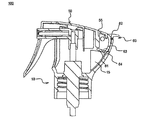
図1は、本発明の実施態様に記載の小型手動式噴霧器の模式的な断面図である。 FIG. 1 is a schematic cross-sectional view of a small manual sprayer according to an embodiment of the present invention.
図1において示される如く、小型手動式噴霧器100は本体10、手動式ポンプ20、ボタン30、噴霧ノズル40、トリガー50、およびロッキング装置60を含む。本体10は小型手動式噴霧器100の外部を形成し、そして内容物を保有する容器(示されていない)の頂部にカップリングされる。手動式ポンプ20は本体10の内部に搭載され、そしてボタン30の上下運動によって内容物を容器から外へ吸い出す。ボタン30は中空構造を有し、そしてボタン30が手動式ポンプ20と連通するように、手動式ポンプ20の頂部上に搭載される。噴霧ノズル40は、ボタン30内に形成される水平溝中に搭載される。噴霧ノズル40を含むボタン30の前端部分は、トリガー50の一方の側に露出され、一方、トリガー50の他方の側は本体10に回転可能にカップリングされる。ロッキング装置60は、トリガー50および本体10が互いに回転可能にカップリングされる回転カップリング部分に置かれている。
As shown in FIG. 1, the small
図1は、ロックされた状態における小型手動式噴霧器100のロッキング装置60を説明しており、ここでロッキング装置60が、内部リブ55との接触状態を保持しながら、トリガー50の内部リブ55および本体10の突起部分15の間に挿入され、このことによってトリガー50の下方への回転が防がれる。
FIG. 1 illustrates the
図2は図1の本体の模式的な斜視図であり、そして図3は図2の本体の模式的な垂直断面図である。 2 is a schematic perspective view of the main body of FIG. 1, and FIG. 3 is a schematic vertical sectional view of the main body of FIG.
図1と組合せて、図2および3を参照すると、本体10は、開放頂部12を持つ実質的に円筒状の本体11を有する。
Referring to FIGS. 2 and 3 in combination with FIG. 1, the
本体10は、前方部分13を通して本体10の内部が露出されるように、U形に切り出される前方部分13を有する。このことによってトリガー50のハンドルの下方への回転のために必要なスペースが確保される。
The
本体10の後方部分14は、ロッキング装置60のアーチ形支持部が本体の後方部分14の内面と密接できるように、円筒体11の外面の中間部分から頂部へとサイズが徐々に増す、外側に突き出した形を有する。突起部分15は、突起部分15がロッキング装置60の構成部品であるロッキング部分と接触するように、後方部分14の内面上に形成される。
The
本体10はその底部でカップリング溝16を有する。カップリング溝16は、内容物を保持する容器へのカップリングのための良好なシールを供するためにきつくねじ込まれる。本体10もまた、その上方部分で凹状の溝17を有する。
The
図4は図1のボタンの模式的な斜視図であり、そして図5は図1の噴霧ノズルの模式的な斜視図である。 4 is a schematic perspective view of the button of FIG. 1, and FIG. 5 is a schematic perspective view of the spray nozzle of FIG.
図1と組合せて、図4および5を参照すると、ボタン30は垂直溝31、水平溝32、および突起33を含む。垂直溝31および水平溝32の各々は中空の円筒状構造を有する。水平溝32は垂直溝31から延び、そして外側に突き出る突起33は、垂直溝31および水平溝32の間の曲がったジョイント上に形成される。
4 and 5 in combination with FIG. 1, the
噴霧ノズル40は、円筒状シャフト41、および円筒状シャフト41の外面上に放射状に形成されるリブ42を含む。噴霧ノズル40は、放射状の流路がリブ42、および水平溝32の内面の間に形成されるように、ボタン30の水平溝32の内部に搭載される。トリガー50のハンドルが引かれるときに、内容物が最初に垂直溝31を通過し、そして次に水平溝32および噴霧ノズルのリブ42の間に形成される放射状流路を通過する際に、広く分散される。
The
図6は、図1のトリガーの模式的な断面図である。 FIG. 6 is a schematic cross-sectional view of the trigger of FIG.
図1および3を組合せて、図6を参照すると、トリガー50は、本体10の頂部に置かれたカバー51、および噴霧器を作動させるためのハンドル52を含む。
Referring to FIG. 6 in combination with FIGS. 1 and 3, the
カバー51はアーチ形状をしており、そして本体10の開放頂部を覆う。カバー51はボタン30を押し下げるためのボタン押し下げ部分53、トリガーガイド54、内部リブ55、およびカバー51を本体10に回転可能にカップリングさせるためのカップリング部分56を含む。
The
ボタン押し下げ部分53は、ボタン30に対応する位置で、カバー51の内面上に形成される。ボタン押し下げ部分53は、トリガー50が下方に回転されるときに、ボタン押し下げ部分53がボタン30を下方に押すことができるように、ボタン30を押し下げるためのある高さで突き出ている。内部リブ55はカバー51の後方内面から下方に延びる。上方に延びる突起部分15は、トリガー50の内部リブ55に対応する位置で、本体10の内部に形成される。
The button push-
内部リブ55および突起部分15は、その間で空隙を形成し、それによって、トリガー50のハンドル52が引かれたときに、本体10に対してトリガー50の回転が可能となるように、互いから離れて間隔を開けられている。トリガー50がロックされた状態にあるときに、内部リブ55および突起部分15の間の空隙内にロッキング装置60の前端部分が挿入される。
The
カップリング部分56はトリガー50の内部リブ55の後方側に置かれ、そして円形の突起の形で形成される。カップリング部分56は、本体10をトリガー50にカップリングさせるために、凹状の溝17中に挿入される。
Coupling
トリガー50のハンドル52は、ハンドル52が指で容易に掴むことができるように、カバー51の左側から下方にある長さまで延びる。放射状の流路の出口57はハンドル52の上方部分で露出される。
The
図7は、図1のロッキング装置の模式的な斜視図である。 FIG. 7 is a schematic perspective view of the locking device of FIG.
図1および6を組合せて、図7を参照すると、ロッキング装置60は、トリガー50の操作を可能または不可能ならしめるためのロッキング部分61、およびロッキング装置60を上方または下方に操作するために、噴霧器100の外側に露出される操作部分62を含む。
Referring to FIG. 7 in combination with FIGS. 1 and 6, the locking
ロッキング部分61は、ロッキング部分61がトリガー50の内部リブ55および本体10の突起部分15の間の空隙内に容易に挿入されまたはそこから取り除かれるように、水平の板の形に(つまり、上方から見たときに板の形に)形成されている。ロッキング部分61が下方に動かされるときに、ロッキング部分61は、トリガー50を固定するために、トリガー50の内部リブ55と接触するようになる。
The locking
操作部分62の一部は、小型手動式噴霧器100の外側に露出されている。操作部分62の露出された部分は、水平の半円形(つまり、上方から見たときに半円形)をしており、そして操作部分62の底は支持部63に接続されている。
A part of the
支持部63の底部は、ロッキング部分にヒンジ状に接続されている。溝64は、ジョイントで曲がることを助けるために、ロッキング部分61および支持部63の間のジョイントの下方部分に形成される。
The bottom part of the
支持部63は、支持部が本体10の上方部分に対応する形状を有し、そして操作部分62が上方向に操作されるときに、本体10の上方内面と密接した状態になる。
The
図8は、図1のロッキング装置がロックされていない状態にあるときの、小型手動式噴霧器の模式的な断面図であり、そして図9は、図8の状態においてトリガーが引かれたときの、小型手動式噴霧器の模式的な断面図である。 FIG. 8 is a schematic cross-sectional view of a miniature manual sprayer when the locking device of FIG. 1 is in an unlocked state, and FIG. 9 is when the trigger is pulled in the state of FIG. It is typical sectional drawing of a small manual sprayer.
図8において示される如く、ロッキング装置60の操作部分62が上方に動かされるときに、トリガーの操作が可能になる。操作部分62が上方に動かされるにつれて、ロッキング部分61および支持部63も上方に動かされ、一方、ロッキング部分61は、トリガー50の内部リブ55および本体10の突起部分15の間から取り除かれる。支持部63およびロッキング部分61の間のジョイントは、ロッキング装置60が上方に動かされるときに、ロッキング装置60がジョイントで容易に曲がるように、ヒンジ構造64を有する。本体10の内面と密接した状態を保持しながら、そのことによって、トリガー50の内部リブ55および本体10の突起部分15の間の空隙を開けながら、支持部63は上方に動かされる。
As shown in FIG. 8, when the operating
従って、図9において示される如く、トリガー50は、ロッキング装置60のロッキング部分61がトリガー50の内部リブ55と接触するようになるまで、下方に回転される。ここで、トリガー50のハンドル52は、本体10の凹状の溝(示されていない)およびトリガー50のカップリング部分56の両方に対応する軸の周りに回転される。
Accordingly, as shown in FIG. 9, the
トリガー50が下方に回転される間、トリガー50のトリガーガイド54はボタン30を下方に押す。このことによって手動式ポンプ20は容器(示されていない)中の内容物を吸い出すことが可能となる。吸い出された内容物はボタン30の垂直溝31および水平溝32を通過し、そして次に噴霧器から放出される。
While the
図10は、図1の小型手動式噴霧器の操作シーケンスを説明するための模式的な斜視図である。 FIG. 10 is a schematic perspective view for explaining an operation sequence of the small manual sprayer of FIG.
図10において示される如く、最初に、ロックされた状態にあるロッキング装置60の操作部分62が上方に動かされる。次いで、U形状に開かれている本体10の前方部分13を通してハンドル52が下方に回転されるように、トリガー50のハンドル52が引かれる。このことによって、トリガー50がボタン(示されていない)を押し下げることが可能となり、容器(示されていない)中に貯蔵された内容物をポンプが吸い出すことになる。その結果、内容物が噴霧器の外側の望まれる位置へ均一に噴霧される。
As shown in FIG. 10, first, the operating
本発明に記載の小型手動式噴霧器は、噴霧器を落としたりまたはトリガーに故意でなく外力がかけられたことによる、トリガーが故意でなく押し下げられることを防ぎ、そのことによって、ロッキング装置が噴霧を邪魔しない位置に供される故に、内容物の損失を防ぐ。 The small manual sprayer according to the present invention prevents the trigger from being pushed down unintentionally due to dropping the sprayer or unintentional external force being applied to the trigger, so that the locking device prevents the spraying. Since it is provided in a position where it is not, loss of contents is prevented.
本発明の好ましい実施態様が説明目的のために開示されているものの、当業者は、付随の請求項に開示された本発明の範囲および精神から逸脱することなく、種々の修正、追加および置換が可能であると理解するであろう。 While preferred embodiments of the present invention have been disclosed for purposes of illustration, those skilled in the art may make various modifications, additions and substitutions without departing from the scope and spirit of the invention as disclosed in the appended claims. You will understand that it is possible.
Claims (7)
(a)前記噴霧器の外部を形成し、内容物を保持する容器の頂部にカップリングされている本体;
(b)前記本体の内部に搭載された、ボタンの上下運動によって内容物を前記容器から外へ吸い出すための手動式ポンプ;
(c)前記手動式ポンプの頂部上に搭載され、前記手動式ポンプと連通するように中空構造を有するボタンであって、前記手動式ポンプと連通する垂直な溝および前記垂直な溝から延びる水平な溝を含むボタン;
(d)前記ボタンにおける前記水平溝中に搭載された噴霧ノズル;
(e)一方の側で、前記噴霧ノズルを含む前記ボタンの前端部分が露出し、他方の側で、前記本体と回転可能にカップリングされるトリガーであって、前記トリガーのハンドルが引かれると、前記トリガーが前記ボタンを下方に押し、前記ハンドルが開放されると、前記トリガーが復元力のために元の位置に戻るトリガー;および
(f)前記トリガーと前記本体の回転カップリング部分に備えられ、必要に応じて前記本体に対する前記トリガーの操作を可能または不可能ならしめるロッキング装置
を含み、
前記トリガー上の、前記回転カップリング部分の前方部分に、下方に延びる内部リブが形成され、
前記本体の内部の、前記内部リブに対応する位置に、上方に延びる突き出し部分が形成され、
前記内部リブと突き出し部分が、それらの間に空隙を形成するように、互いから離れて間隔を開けられ、
前記トリガーのハンドルが引かれたときに、前記空隙によって前記トリガーが前記本体に対して回転でき、
前記トリガーがロックされた状態にあるときに、前記ロッキング装置の前端部分が、前記内部リブと前記突き出し部分の間の前記空隙内に挿入される
ことを特徴とする噴霧器。 A small-sized manual sprayer for spraying a small amount of contents, the following (a) to (f):
(A) a body that forms the exterior of the sprayer and is coupled to the top of a container that holds the contents;
(B) a manual pump mounted inside the main body for sucking the contents out of the container by moving the button up and down;
(C) a button mounted on the top of the manual pump and having a hollow structure so as to communicate with the manual pump, the vertical groove communicating with the manual pump and the horizontal extending from the vertical groove Button with a groove;
(D) a spray nozzle mounted in the horizontal groove in the button;
(E) On one side, a front end portion of the button including the spray nozzle is exposed, and on the other side, a trigger that is rotatably coupled to the main body, the handle of the trigger being pulled A trigger that pushes the button down and the trigger returns to its original position for restoring force when the handle is released; and (f) a rotary coupling portion of the trigger and the body. A locking device that enables or disables operation of the trigger on the body as required ,
An internal rib extending downward is formed in the front portion of the rotary coupling portion on the trigger,
A protruding portion extending upward is formed in a position corresponding to the internal rib in the main body,
The inner rib and the protruding portion are spaced apart from each other so as to form a gap therebetween;
When the trigger handle is pulled, the gap allows the trigger to rotate relative to the body,
When the trigger is in a locked state, the front end portion of the locking device is inserted into the gap between the inner rib and the protruding portion.
A nebulizer characterized by that.
前記トリガーの操作を不可能ならしめる、または可能ならしめるために、前記空隙内に挿入され、またはそこから取り除かれるロッキング部分;および
前記噴霧器から露出しながら前記ロッキング部分から延び、前記ロッキング部分が前記空隙内に挿入されまたはそこから取り除かれるように操作される操作部分;
を含むことを特徴とする請求項1に記載の噴霧器。 Said locking device;
A locking portion that is inserted into or removed from the gap to make operation of the trigger impossible or possible; and extends from the locking portion while being exposed from the sprayer, the locking portion being An operating part operated to be inserted into or removed from the gap;
The nebulizer according to claim 1 , comprising:
Applications Claiming Priority (3)
| Application Number | Priority Date | Filing Date | Title |
|---|---|---|---|
| KR2020080010167U KR200449781Y1 (en) | 2008-07-30 | 2008-07-30 | Small Hand-Operated Sprayer |
| KR20-2008-0010167 | 2008-07-30 | ||
| PCT/KR2009/004000 WO2010013908A2 (en) | 2008-07-30 | 2009-07-20 | Small manual sprayer |
Publications (2)
| Publication Number | Publication Date |
|---|---|
| JP2011529393A JP2011529393A (en) | 2011-12-08 |
| JP5597632B2 true JP5597632B2 (en) | 2014-10-01 |
Family
ID=41610820
Family Applications (1)
| Application Number | Title | Priority Date | Filing Date |
|---|---|---|---|
| JP2011521016A Expired - Fee Related JP5597632B2 (en) | 2008-07-30 | 2009-07-20 | Small manual sprayer |
Country Status (6)
| Country | Link |
|---|---|
| US (1) | US8556126B2 (en) |
| EP (1) | EP2319627A4 (en) |
| JP (1) | JP5597632B2 (en) |
| KR (1) | KR200449781Y1 (en) |
| CN (1) | CN102112237B (en) |
| WO (1) | WO2010013908A2 (en) |
Families Citing this family (11)
| Publication number | Priority date | Publication date | Assignee | Title |
|---|---|---|---|---|
| KR200449781Y1 (en) * | 2008-07-30 | 2010-08-10 | 주식회사 종우실업 | Small Hand-Operated Sprayer |
| USD676760S1 (en) | 2011-03-03 | 2013-02-26 | S.C. Johnson & Son, Inc. | Combined trigger and bottle |
| USD661187S1 (en) | 2011-03-03 | 2012-06-05 | S.C. Johnson & Son, Inc. | Trigger |
| DE102014009155A1 (en) * | 2013-10-18 | 2015-04-23 | Aptar Dortmund Gmbh | pump |
| MX2018000868A (en) * | 2015-07-23 | 2018-07-06 | J Schalitz William | Disposable soap dispenser. |
| WO2017111037A1 (en) * | 2015-12-24 | 2017-06-29 | 花王株式会社 | Liquid-discharging container |
| JP6670671B2 (en) * | 2016-04-28 | 2020-03-25 | 株式会社吉野工業所 | Dispenser |
| CN106697607B (en) * | 2017-02-18 | 2019-03-15 | 中山市美捷时包装制品有限公司 | A kind of rotary self-locking type aerosol actuator |
| EP3686122B1 (en) * | 2017-09-20 | 2024-04-17 | Yoshino Kogyosho Co., Ltd. | Discharger |
| CN108820586B (en) * | 2018-08-08 | 2023-11-03 | 广东好顺欧迪斯科技股份有限公司 | Spray head and insect-expelling spray bottle |
| CN113042245B (en) * | 2021-03-09 | 2022-05-17 | 宁波圣捷喷雾泵有限公司 | Spray gun |
Family Cites Families (24)
| Publication number | Priority date | Publication date | Assignee | Title |
|---|---|---|---|---|
| US4082223A (en) * | 1975-12-06 | 1978-04-04 | Yoshino Kogyosho Co., Ltd. | Trigger type spraying device |
| US4159067A (en) * | 1977-06-06 | 1979-06-26 | Akers Edward G | Dispensing pump for container |
| US4245759A (en) * | 1979-05-02 | 1981-01-20 | Nordson Corporation | Adhesive hand gun with swivel connector and safety mechanism |
| US4427134A (en) * | 1981-07-01 | 1984-01-24 | Almouli Albert A | Aerosol dispenser container and actuator therefor |
| IE53550B1 (en) * | 1981-08-10 | 1988-12-07 | Bespak Industries Ltd | Handle assembly for a pressurised dispensing container |
| FR2528328B1 (en) * | 1982-06-11 | 1985-11-22 | Valve Precision Sarl | SPRAYING DEVICE FOR LIQUIDS |
| JPH0639810Y2 (en) * | 1987-10-20 | 1994-10-19 | 株式会社吉野工業所 | Atomizer |
| US4880143A (en) * | 1988-10-20 | 1989-11-14 | Insta-Foam Products | Dispenser and components for high viscosity foam products |
| JPH08196955A (en) * | 1995-01-30 | 1996-08-06 | Yoshino Kogyosho Co Ltd | Pressure accumulation type sprayer fitted with trigger |
| JP3503780B2 (en) * | 1995-08-18 | 2004-03-08 | 株式会社吉野工業所 | Ejector with trigger |
| JPH09192552A (en) | 1996-01-24 | 1997-07-29 | Jun Yanagida | Sprayer |
| US5839616A (en) * | 1997-08-14 | 1998-11-24 | The Procter & Gamble Company | Blow molded container having pivotal connector for an actuation lever |
| US6286723B1 (en) * | 2000-03-06 | 2001-09-11 | Saint-Gobain Calmar Inc. | Self-resetting child-resistant trigger sprayer |
| KR20000063513A (en) * | 2000-07-19 | 2000-11-06 | 김상근 | sprayer |
| US20040182884A1 (en) * | 2002-09-11 | 2004-09-23 | Tetsuya Tada | Auxiliary cover for pump dispenser and vessel attached with pump dispenser |
| JP2004122123A (en) * | 2002-09-11 | 2004-04-22 | Canyon Corp | Auxiliary cover for pump dispenser, and vessel with pump dispenser |
| JP4079261B2 (en) * | 2002-12-27 | 2008-04-23 | 株式会社吉野工業所 | Liquid ejector |
| FR2864823B1 (en) * | 2004-01-05 | 2006-08-18 | Oreal | LOCKING DISTRIBUTION HEAD |
| JP2005219003A (en) * | 2004-02-06 | 2005-08-18 | Canyon Corp | Pump dispenser with trigger |
| JP4502188B2 (en) * | 2004-05-31 | 2010-07-14 | 株式会社吉野工業所 | Foam spout container with trigger |
| US20060138176A1 (en) * | 2004-11-29 | 2006-06-29 | L'oreal | Device for packaging and dispensing a product |
| JP2008030798A (en) * | 2006-07-28 | 2008-02-14 | Mitani Valve Co Ltd | Injection device, pump sprayer, and aerosol sprayer |
| US8225964B2 (en) * | 2008-06-13 | 2012-07-24 | Nordson Corporation | Self-locking handheld adhesive dispensers and methods of using such adhesive dispensers |
| KR200449781Y1 (en) * | 2008-07-30 | 2010-08-10 | 주식회사 종우실업 | Small Hand-Operated Sprayer |
-
2008
- 2008-07-30 KR KR2020080010167U patent/KR200449781Y1/en not_active IP Right Cessation
-
2009
- 2009-07-20 US US13/001,241 patent/US8556126B2/en not_active Expired - Fee Related
- 2009-07-20 JP JP2011521016A patent/JP5597632B2/en not_active Expired - Fee Related
- 2009-07-20 WO PCT/KR2009/004000 patent/WO2010013908A2/en active Application Filing
- 2009-07-20 CN CN200980129740.2A patent/CN102112237B/en not_active Expired - Fee Related
- 2009-07-20 EP EP09803113A patent/EP2319627A4/en not_active Withdrawn
Also Published As
| Publication number | Publication date |
|---|---|
| JP2011529393A (en) | 2011-12-08 |
| US8556126B2 (en) | 2013-10-15 |
| CN102112237B (en) | 2015-05-20 |
| US20110155764A1 (en) | 2011-06-30 |
| CN102112237A (en) | 2011-06-29 |
| EP2319627A2 (en) | 2011-05-11 |
| KR20100001398U (en) | 2010-02-09 |
| WO2010013908A2 (en) | 2010-02-04 |
| EP2319627A4 (en) | 2012-05-09 |
| KR200449781Y1 (en) | 2010-08-10 |
| WO2010013908A3 (en) | 2010-03-25 |
Similar Documents
| Publication | Publication Date | Title |
|---|---|---|
| JP5597632B2 (en) | Small manual sprayer | |
| JP4679142B2 (en) | Lockable dispensing head | |
| US20180127194A1 (en) | Aerosol actuators, devices and methods of making and using the same | |
| EP1197266B1 (en) | Actuation device for manually operated pump sprayer | |
| CN104364168A (en) | Trigger operated aerosol dispenser | |
| TWI358325B (en) | Nebuliser micro-pump provideo with an element for | |
| CN101578057A (en) | Nozzle retractable dispenser | |
| JP2014507346A (en) | Spray actuator | |
| CZ20041046A3 (en) | Child-resistant trigger actuated liquid sprayer and method for operating the same | |
| JP5378177B2 (en) | Mixed dispenser | |
| JP2008114103A (en) | Trigger spray and spray container equipped with the same | |
| TW202325410A (en) | A spray gun handle and trigger attachment | |
| JP5530224B2 (en) | Cap for aerosol container | |
| US7690854B2 (en) | Device for packaging and applying a product, in particular a cosmetic product | |
| JP2004122123A (en) | Auxiliary cover for pump dispenser, and vessel with pump dispenser | |
| JP6640447B2 (en) | Delivery devices and packaging with such devices | |
| JP5047498B2 (en) | Two-component sprayer | |
| JP7307496B2 (en) | Content injection unit | |
| WO2006032036A1 (en) | Actuator cap and product refill for a housing | |
| JP4767527B2 (en) | Spray structure | |
| NL2018736B1 (en) | Cap for a pressurized container with a dispensing unit | |
| JP2019182470A (en) | Jet pump and jet container | |
| JP4417097B2 (en) | Aerosol injection device | |
| JPH09299837A (en) | Atomizer | |
| JPH09142553A (en) | Push-button device of aerosol container |
Legal Events
| Date | Code | Title | Description |
|---|---|---|---|
| A621 | Written request for application examination |
Free format text: JAPANESE INTERMEDIATE CODE: A621 Effective date: 20120523 |
|
| A977 | Report on retrieval |
Free format text: JAPANESE INTERMEDIATE CODE: A971007 Effective date: 20131121 |
|
| A131 | Notification of reasons for refusal |
Free format text: JAPANESE INTERMEDIATE CODE: A131 Effective date: 20131203 |
|
| A521 | Request for written amendment filed |
Free format text: JAPANESE INTERMEDIATE CODE: A523 Effective date: 20140228 |
|
| A131 | Notification of reasons for refusal |
Free format text: JAPANESE INTERMEDIATE CODE: A131 Effective date: 20140325 |
|
| A521 | Request for written amendment filed |
Free format text: JAPANESE INTERMEDIATE CODE: A523 Effective date: 20140624 |
|
| TRDD | Decision of grant or rejection written | ||
| A01 | Written decision to grant a patent or to grant a registration (utility model) |
Free format text: JAPANESE INTERMEDIATE CODE: A01 Effective date: 20140722 |
|
| A61 | First payment of annual fees (during grant procedure) |
Free format text: JAPANESE INTERMEDIATE CODE: A61 Effective date: 20140811 |
|
| R150 | Certificate of patent or registration of utility model |
Ref document number: 5597632 Country of ref document: JP Free format text: JAPANESE INTERMEDIATE CODE: R150 |
|
| LAPS | Cancellation because of no payment of annual fees |