JP5596870B2 - Measuring probe - Google Patents
Measuring probe Download PDFInfo
- Publication number
- JP5596870B2 JP5596870B2 JP2013548689A JP2013548689A JP5596870B2 JP 5596870 B2 JP5596870 B2 JP 5596870B2 JP 2013548689 A JP2013548689 A JP 2013548689A JP 2013548689 A JP2013548689 A JP 2013548689A JP 5596870 B2 JP5596870 B2 JP 5596870B2
- Authority
- JP
- Japan
- Prior art keywords
- fiber
- light receiving
- measurement
- illumination
- light
- Prior art date
- Legal status (The legal status is an assumption and is not a legal conclusion. Google has not performed a legal analysis and makes no representation as to the accuracy of the status listed.)
- Active
Links
Images


Classifications
-
- A—HUMAN NECESSITIES
- A61—MEDICAL OR VETERINARY SCIENCE; HYGIENE
- A61B—DIAGNOSIS; SURGERY; IDENTIFICATION
- A61B1/00—Instruments for performing medical examinations of the interior of cavities or tubes of the body by visual or photographical inspection, e.g. endoscopes; Illuminating arrangements therefor
- A61B1/06—Instruments for performing medical examinations of the interior of cavities or tubes of the body by visual or photographical inspection, e.g. endoscopes; Illuminating arrangements therefor with illuminating arrangements
- A61B1/07—Instruments for performing medical examinations of the interior of cavities or tubes of the body by visual or photographical inspection, e.g. endoscopes; Illuminating arrangements therefor with illuminating arrangements using light-conductive means, e.g. optical fibres
-
- A—HUMAN NECESSITIES
- A61—MEDICAL OR VETERINARY SCIENCE; HYGIENE
- A61B—DIAGNOSIS; SURGERY; IDENTIFICATION
- A61B1/00—Instruments for performing medical examinations of the interior of cavities or tubes of the body by visual or photographical inspection, e.g. endoscopes; Illuminating arrangements therefor
- A61B1/00163—Optical arrangements
- A61B1/00165—Optical arrangements with light-conductive means, e.g. fibre optics
-
- A—HUMAN NECESSITIES
- A61—MEDICAL OR VETERINARY SCIENCE; HYGIENE
- A61B—DIAGNOSIS; SURGERY; IDENTIFICATION
- A61B1/00—Instruments for performing medical examinations of the interior of cavities or tubes of the body by visual or photographical inspection, e.g. endoscopes; Illuminating arrangements therefor
- A61B1/012—Instruments for performing medical examinations of the interior of cavities or tubes of the body by visual or photographical inspection, e.g. endoscopes; Illuminating arrangements therefor characterised by internal passages or accessories therefor
- A61B1/0125—Endoscope within endoscope
-
- A—HUMAN NECESSITIES
- A61—MEDICAL OR VETERINARY SCIENCE; HYGIENE
- A61B—DIAGNOSIS; SURGERY; IDENTIFICATION
- A61B1/00—Instruments for performing medical examinations of the interior of cavities or tubes of the body by visual or photographical inspection, e.g. endoscopes; Illuminating arrangements therefor
- A61B1/012—Instruments for performing medical examinations of the interior of cavities or tubes of the body by visual or photographical inspection, e.g. endoscopes; Illuminating arrangements therefor characterised by internal passages or accessories therefor
- A61B1/018—Instruments for performing medical examinations of the interior of cavities or tubes of the body by visual or photographical inspection, e.g. endoscopes; Illuminating arrangements therefor characterised by internal passages or accessories therefor for receiving instruments
-
- A—HUMAN NECESSITIES
- A61—MEDICAL OR VETERINARY SCIENCE; HYGIENE
- A61B—DIAGNOSIS; SURGERY; IDENTIFICATION
- A61B5/00—Measuring for diagnostic purposes; Identification of persons
- A61B5/0059—Measuring for diagnostic purposes; Identification of persons using light, e.g. diagnosis by transillumination, diascopy, fluorescence
- A61B5/0082—Measuring for diagnostic purposes; Identification of persons using light, e.g. diagnosis by transillumination, diascopy, fluorescence adapted for particular medical purposes
- A61B5/0084—Measuring for diagnostic purposes; Identification of persons using light, e.g. diagnosis by transillumination, diascopy, fluorescence adapted for particular medical purposes for introduction into the body, e.g. by catheters
-
- G—PHYSICS
- G02—OPTICS
- G02B—OPTICAL ELEMENTS, SYSTEMS OR APPARATUS
- G02B6/00—Light guides; Structural details of arrangements comprising light guides and other optical elements, e.g. couplings
- G02B6/04—Light guides; Structural details of arrangements comprising light guides and other optical elements, e.g. couplings formed by bundles of fibres
- G02B6/06—Light guides; Structural details of arrangements comprising light guides and other optical elements, e.g. couplings formed by bundles of fibres the relative position of the fibres being the same at both ends, e.g. for transporting images
-
- A—HUMAN NECESSITIES
- A61—MEDICAL OR VETERINARY SCIENCE; HYGIENE
- A61B—DIAGNOSIS; SURGERY; IDENTIFICATION
- A61B1/00—Instruments for performing medical examinations of the interior of cavities or tubes of the body by visual or photographical inspection, e.g. endoscopes; Illuminating arrangements therefor
- A61B1/005—Flexible endoscopes
Description
本発明は、生体組織の光学特性を測定する生体光学測定装置に接続される測定プローブに関する。 The present invention relates to a measurement probe connected to a biological optical measurement device that measures optical characteristics of biological tissue.
近年、生体組織に照明光を照射し、生体組織から反射または散乱された検出光の測定値に基づいて、生体組織の性状を推定する生体光学測定装置が知られている。生体光学測定装置は、消化器等の臓器を観察する内視鏡と組み合わせて使用される。このような生体光学測定装置として、空間コヒーレンス長の短い低コヒーレントの白色光を測定プローブの照明ファイバ先端から生体組織に照射し、複数の角度の散乱光の強度分布を複数の受光ファイバを用いて測定することによって、生体組織の性状を検出するLEBS(Low-Coherence Enhanced Backscattering)を用いた生体光学測定装置が提案されている(特許文献1〜3参照)。
2. Description of the Related Art In recent years, there are known bio-optical measurement apparatuses that irradiate a living tissue with illumination light and estimate the properties of the living tissue based on measured values of detection light reflected or scattered from the living tissue. The bio-optical measurement device is used in combination with an endoscope for observing an organ such as a digestive organ. As such a bio-optical measurement device, low coherence white light with a short spatial coherence length is irradiated onto the living tissue from the tip of the illumination fiber of the measurement probe, and the intensity distribution of scattered light at a plurality of angles is measured using a plurality of light receiving fibers. A bio-optical measurement device using LEBS (Low-Coherence Enhanced Backscattering) that detects the properties of a living tissue by measurement has been proposed (see
しかしながら、上述した技術では、測定プローブが内視鏡装置の処置具チャンネルに挿入できるほど細径化されていなかった。このため、内視鏡装置で診断した後に、測定プローブを被検体内に挿入して検査を行わなければならず、患者に大きな負担がかかるという問題点があった。 However, in the above-described technique, the measurement probe has not been reduced in diameter so that it can be inserted into the treatment instrument channel of the endoscope apparatus. For this reason, after diagnosing with the endoscope apparatus, the measurement probe has to be inserted into the subject to perform an examination, and there is a problem that a heavy burden is placed on the patient.
この課題を解決するために、内視鏡装置の処置具チャンネルに対して、挿入可能な程度まで測定プローブの細径化することが考えられる。しかしながら、適切な細径化を行わないと正確な測定を行うことができないという問題点があった。 In order to solve this problem, it is conceivable to reduce the diameter of the measurement probe to such an extent that it can be inserted into the treatment instrument channel of the endoscope apparatus. However, there has been a problem that accurate measurement cannot be performed unless appropriate diameter reduction is performed.
本発明は、上記に鑑みてなされたものであって、内視鏡装置の処置具チャンネルに挿入可能であるとともに、正確な測定を行うことができる測定プローブを提供することを目的とする。 The present invention has been made in view of the above, and an object of the present invention is to provide a measurement probe that can be inserted into a treatment instrument channel of an endoscope apparatus and can perform accurate measurement.
上述した課題を解決し、目的を達成するために、本発明にかかる測定プローブは、生体組織に対して光学測定を行う生体光学測定装置に着脱自在に接続される測定プローブであって、前記生体組織に照明光を照射する照明ファイバと、前記生体組織で反射および/または散乱した照明光の戻り光を受光する複数の受光ファイバと、を備え、前記照明ファイバおよび前記受光ファイバは、以下の条件式を満たすことを特徴とする。
0.10<NA<0.30 ・・・(1)
15μm<Dcore<45μm ・・・(2)
0.40<Dcore/Dclad<0.80 ・・・(3)
ただし、NAは、前記照明ファイバおよび前記受光ファイバそれぞれの開口数を表し、Dcoreは、前記照明ファイバおよび前記受光ファイバそれぞれのコア径を表し、Dcladは、前記照明ファイバおよび前記受光ファイバそれぞれのクラッド径を表す。In order to solve the above-described problems and achieve the object, a measurement probe according to the present invention is a measurement probe that is detachably connected to a biological optical measurement device that performs optical measurement on biological tissue, An illumination fiber that irradiates the tissue with illumination light, and a plurality of light receiving fibers that receive return light of the illumination light reflected and / or scattered by the living tissue. The illumination fiber and the light reception fiber satisfy the following conditions: It is characterized by satisfying the formula.
0.10 <NA <0.30 (1)
15 μm <Dcore <45 μm (2)
0.40 <Dcore / Dclad <0.80 (3)
However, NA represents the numerical aperture of each of the illumination fiber and the light receiving fiber, Dcore represents the core diameter of each of the illumination fiber and the light receiving fiber, and Dclad represents the cladding diameter of each of the illumination fiber and the light receiving fiber. Represents.
また、本発明にかかる測定プローブは、上記発明において、前記照明ファイバおよび前記受光ファイバは、ステップインデックス型シングルコアファイバであることを特徴とする。 In the measurement probe according to the present invention as set forth in the invention described above, the illumination fiber and the light receiving fiber are step index type single core fibers.
また、本発明にかかる測定プローブは、上記発明において、当該測定プローブの先端部に設けられ、長手方向に対して斜めに切り欠かれた傾斜面を有し、前記照明ファイバが出射する光を中継して前記生体組織に照射する光学素子をさらに備え、前記光学素子の当該測定プローブの長手方向の長さDRは、以下の条件式を満たすことを特徴とする。
1mm<DR<10mm ・・・(4)Further, the measurement probe according to the present invention is the above-described invention, wherein the measurement probe has an inclined surface that is provided at the distal end of the measurement probe and is obliquely cut out with respect to the longitudinal direction, and relays light emitted from the illumination fiber. further comprising an optical element which to irradiate the living body tissue, the longitudinal length D R of the measuring probe of the optical element, and satisfies the following conditional expression.
1 mm <D R <10 mm (4)
また、本発明にかかる測定プローブは、上記発明において、前記光学素子のd線に対する屈折率Ndは、以下の条件式を満たすことを特徴とする。
1.5<Nd<1.6 ・・・(5)In the measurement probe according to the present invention as set forth in the invention described above, the refractive index Nd for the d-line of the optical element satisfies the following conditional expression.
1.5 <Nd <1.6 (5)
また、本発明にかかる測定プローブは、上記発明において、当該測定プローブの先端部の最大外径Doutは、以下の条件式を満たすことを特徴とする。
0.50mm<Dout<2.80mm ・・・(6)In the measurement probe according to the present invention, the maximum outer diameter Dout of the distal end portion of the measurement probe satisfies the following conditional expression.
0.50 mm <Dout <2.80 mm (6)
本発明にかかる測定プローブによれば、内視鏡装置の処置具チャンネルに挿入可能であるとともに、正確な測定を行うことができるという効果を奏する。 The measurement probe according to the present invention can be inserted into the treatment instrument channel of the endoscope apparatus, and has an effect that an accurate measurement can be performed.
以下、図面を参照して、本発明にかかる測定プローブの好適な実施の形態を詳細に説明する。なお、この実施の形態によってこの発明が限定されるものではない。また、図面の記載において、同一の部分には同一の符号を付して説明する。また、図面は、模式的なものであり、各部材の厚みと幅との関係、各部材の比率等は、現実と異なることに留意する必要がある。また、図面の相互間においても、互いの寸法の関係や比率が異なる部分が含まれる。 Hereinafter, preferred embodiments of a measurement probe according to the present invention will be described in detail with reference to the drawings. The present invention is not limited to the embodiments. In the description of the drawings, the same portions are denoted by the same reference numerals for description. Further, the drawings are schematic, and it is necessary to note that the relationship between the thickness and width of each member, the ratio of each member, and the like are different from actual ones. Moreover, the part from which the relationship and ratio of a mutual dimension differ also in between drawings is contained.
図1は、本発明の一実施の形態にかかる生体光学測定システムの構成を模式的に示すブロック図である。図1に示す生体光学測定システム1は、散乱体である生体組織等の測定対象物に対して光学測定を行って測定対象物の性状(特性)を検出する生体光学測定装置2と、生体光学測定装置2に着脱自在であり、被検体内に挿入される測定用の測定プローブ3と、を備える。
FIG. 1 is a block diagram schematically showing a configuration of a biological optical measurement system according to an embodiment of the present invention. A
まず、生体光学測定装置2について説明する。生体光学測定装置2は、電源21と、光源部22と、接続部23と、受光部24と、入力部25と、出力部26と、記録部27と、制御部28と、を備える。電源21は、生体光学測定装置2の各構成要素に電力を供給する。
First, the
光源部22は、白色LED(Light Emitting Diode)、キセノンランプ、タングステンランプおよびハロゲンランプのようなインコヒーレント光源と、必要に応じて一または複数のレンズ、たとえば集光レンズやコリメートレンズ等を用いて実現される。光源部22は、接続部23を介して測定対象物へ照射する少なくとも一つのスペクトル成分を有するインコヒーレント光を測定プローブ3に出力する。
The light source unit 22 uses an incoherent light source such as a white LED (Light Emitting Diode), a xenon lamp, a tungsten lamp, and a halogen lamp, and one or a plurality of lenses, for example, a condensing lens or a collimating lens, as necessary. Realized. The light source unit 22 outputs to the
接続部23は、測定プローブ3のコネクタ部31を生体光学測定装置2に着脱自在に接続する。接続部23は、光源部22が発する光を測定プローブ3に出力するとともに、測定プローブ3から出射され測定対象物で反射および/または散乱した照明光の戻り光を受光部24に出力する。接続部23は、測定プローブ3の接続の有無に関する情報を制御部28へ出力する。
The
受光部24は、測定プローブ3から出射された照明光であって測定対象物で反射および/または散乱した照明光の戻り光を受光して測定する。受光部24は、複数の分光測定器や受光センサ等を用いて実現される。具体的には、受光部24は、分光測定器が後述する測定プローブ3の受光ファイバの数に応じて設けられる。受光部24は、測定プローブ3から入射された散乱光のスペクトル成分および強度分布を測定して、各波長の測定を行う。受光部24は、測定結果を制御部28へ出力する。
The light receiving unit 24 receives and measures the return light of the illumination light emitted from the
入力部25は、プッシュ式のスイッチやタッチパネル等を用いて実現され、生体光学測定装置2の起動を指示する指示信号または他の各種の動作を指示する指示信号の入力を受け付けて制御部28へ出力する。
The
出力部26は、液晶または有機EL(Electro Luminescence)の表示ディスプレイおよびスピーカ等を用いて実現され、生体光学測定装置2における各種処理に関する情報を出力する。
The
記録部27は、揮発性メモリや不揮発性メモリを用いて実現され、生体光学測定装置2を動作させるための各種プログラム、光学測定処理に使用される各種データや各種パラメータを記録する。記録部27は、生体光学測定装置2の処理中の情報を一時的に記録する。また、記録部27は、生体光学測定装置2の測定結果を記録する。なお、記録部27は、生体光学測定装置2の外部から装着されるメモリカード等を用いて構成されてもよい。
The
制御部28は、CPU(Central Processing Unit)等を用いて構成される。制御部28は、生体光学測定装置2の各部の処理動作を制御する。制御部28は、生体光学測定装置2の各部に対応する指示情報やデータの転送等を行うことによって、生体光学測定装置2の動作を制御する。制御部28は、受光部24による測定結果を記録部27に記録する。制御部28は、演算部28aを有する。
The
演算部28aは、受光部24による測定結果に基づいて、複数の演算処理を行い、測定対象物の性状に関する特性値を演算する。この特性値の種別は、たとえば入力部25が受け付けた指示信号にしたがって設定される。
The
つぎに、測定プローブ3について説明する。複数の光ファイバを内部に配設して実現される。具体的には、測定プローブ3は、測定対象物に照明光を出射する照明ファイバと、測定対象物で反射および/または散乱した照明光の戻り光が異なる角度で入射する複数の受光ファイバとを用いて実現される。測定プローブ3は、生体光学測定装置2の接続部23に着脱自在に接続されるコネクタ部31と、可撓性を有する可撓部32と、光源部22から供給された照明光を照射するとともに、測定対象物からの戻り光を受光する先端部33と、先端部33に設けられた光学素子34と、を備える。
Next, the
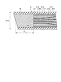
ここで、光学素子34を含む測定プローブ3の先端部33の構成について詳細に説明する。図2は、光学素子34を含む測定プローブ3の先端部33を長手方向に沿って切断した断面を模式的に示す図である。
Here, the configuration of the
図2に示すように、測定プローブ3は、測定対象物に照明光を照射する照明ファイバ311と、測定対象物で反射および/または散乱した照明光の戻り光が入射する第1受光ファイバ312(第1受光チャンネル)、第2受光ファイバ313(第2受光チャンネル)および第3受光ファイバ314(第3受光チャンネル)と、照明ファイバ311、第1受光ファイバ312、第2受光ファイバ313および第3受光ファイバ314それぞれの傷防止や位置を固定するガラス又は樹脂等の被覆部材315と、光学素子34および被覆部材315を外力から保護するガラス又は真鍮等の保護部316と、SUS等のプローブ外皮317と、を備える。
As shown in FIG. 2, the
照明ファイバ311は、ステップインデックス型シングルコアファイバを用いて構成される。照明ファイバ311は、光源部22から出力された照明光を伝播し、光学素子34を介して測定対象物に照明光を照射する。なお、照明ファイバ311の数は、検査項目または測定対象物の種類、たとえば血流や部位に応じて適宜変更することができる。
The
第1受光ファイバ312、第2受光ファイバ313および第3受光ファイバ314は、それぞれステップインデックス型シングルコアファイバを用いて構成される。第1受光ファイバ312、第2受光ファイバ313および第3受光ファイバ314は、光学素子34を介してそれぞれの先端から入射した測定対象物で反射および/または散乱した照明光の戻り光を伝播し、生体光学測定装置2の受光部24に出力する。なお、受光ファイバの数は、検査項目または測定対象物の種類、たとえば血流や部位に応じて適宜変更することができる。
The first
光学素子34は、円柱状をなし、所定の屈折率を有する透過性のガラスを用いて構成される。光学素子34は、測定プローブ3の長手方向に対して斜めに切り欠かれた傾斜面を有する。また、光学素子34は、照明ファイバ311と測定対象物までの距離を固定し、空間コヒーレント長を確実に一定化させた状態で光を照射可能に形成されている。また、光学素子34は、第1受光ファイバ312と測定対象物との距離、第2受光ファイバ313と測定対象物との距離および第3受光ファイバ314と測定対象物との距離をそれぞれ固定し、所定の散乱角度の戻り光を安定して受光可能に形成されている。さらに、光学素子34の端面で測定対象物の表面を平坦化させているため、測定対象物の表面の凹凸形状の影響を受けずに測定対象物の測定を行うことができる。
The
以上のように構成された生体光学測定システム1は、図3に示すように、内視鏡システム100の内視鏡装置110(内視鏡スコープ)に設けられた処置具チャンネル111を介して測定プローブ3が被検体内に挿入され、照明ファイバ311が測定対象物に照明光を照射し、第1受光ファイバ312、第2受光ファイバ313および第3受光ファイバ314がそれぞれ測定対象物で反射および/または散乱した照明光の戻り光を異なる散乱角度で受光して生体光学測定装置2の受光部24に伝播する。その後、演算部28aは、受光部24の測定結果に基づいて、測定対象物の性状の特性値を演算する。
The
上述した生体光学測定システム1で行うLEBSは、干渉光を用いた診断方法であるため、診断方法を変えずに測定プローブ3の細径化を行うためには測定対象物へ照射する光の空間コヒーレント長を一定にする必要がある。このため、照明ファイバ311、第1受光ファイバ312、第2受光ファイバ313および第3受光ファイバ314は、以下の条件式を満たす。
0.10<NA<0.30 ・・・(1)
15μm<Dcore<45μm ・・・(2)
0.40<Dcore/Dclad<0.80 ・・・(3)
ただし、NAは、照明ファイバ311および第1受光ファイバ312〜第3受光ファイバ314それぞれの開口数を表し、Dcoreは、照明ファイバ311および第1受光ファイバ312〜第3受光ファイバ314それぞれのコア径を表し、Dcladは、照明ファイバ311および第1受光ファイバ312〜第3受光ファイバ314それぞれのクラッド径を表す(図4を参照)。
式(1)において、好ましくは、
0.15<NA<0.25 ・・・(1)’
であり、より好ましくは、
0.21<NA<0.23 ・・・(1)”
である。
また、式(2)において、好ましくは、
20μm<Dcore<30μm ・・・(2)’
であり、より好ましくは、
25μm<Dcore<27μm ・・・(2)”
である。
また、式(3)においては、好ましくは、
0.50<Dcore/Dclad<0.75 ・・・(3)’
であり、より好ましくは、
0.70<Dcore/Dclad<0.73 ・・・(3)”
である。The LEBS performed in the above-described
0.10 <NA <0.30 (1)
15 μm <Dcore <45 μm (2)
0.40 <Dcore / Dclad <0.80 (3)
However, NA represents the numerical aperture of each of the
In the formula (1), preferably,
0.15 <NA <0.25 (1) ′
And more preferably
0.21 <NA <0.23 (1) "
It is.
In the formula (2), preferably,
20 μm <Dcore <30 μm (2) ′
And more preferably
25 μm <Dcore <27 μm (2) ”
It is.
In the formula (3), preferably,
0.50 <Dcore / Dclad <0.75 (3) ′
And more preferably
0.70 <Dcore / Dclad <0.73 (3) "
It is.
また、測定プローブ3は、光学素子34の測定プローブ3の長手方向の長さDR(図2を参照)が以下の条件式を満たす。
1mm<DR<10mm ・・・(4)
好ましくは、
3mm<DR<8mm ・・・(4)’
であり、より好ましくは、
5mm<DR<8mm ・・・(4)”
である。In the
1 mm <D R <10 mm (4)
Preferably,
3 mm <D R <8 mm (4) ′
And more preferably
5 mm <D R <8 mm (4) ”
It is.
また、測定プローブ3は、光学素子34のd線(波長587.56nm)に対する屈折率Ndが以下の条件式を満たす。
1.5<Nd<1.6 ・・・(5)In the
1.5 <Nd <1.6 (5)
また、測定プローブ3の先端部33の最大外径Dout(図2参照)は、以下の条件式を満たす。
0.50mm<Dout<2.80mm ・・・(6)
であり、好ましくは、
1.50mm<Dout<2.78mm ・・・(6)’
であり、より好ましくは、
2.50mm<Dout<2.75mm ・・・(6)”
である。Further, the maximum outer diameter Dout (see FIG. 2) of the
0.50 mm <Dout <2.80 mm (6)
And preferably
1.50 mm <Dout <2.78 mm (6) ′
And more preferably
2.50 mm <Dout <2.75 mm (6) "
It is.
また、生体光学測定システム1で行うLEBS法は、以下の式を満たす。
LSC=((λ/Nd)/πDcore)DR ・・・(7)
なお、LSCは、照明光の干渉性を表す定数である。また、λは、照明光の波長を表し、Ndは、光学素子34のd線に対する屈折率を表し、DRは、光学素子34の基端側の端面の中心から先端側の端面の中心までの長さを表す(図2を参照)。このため、上述した条件式(1)〜(6)を満たし、かつ、LSCを一定とする場合、λおよびNdが同じであれば、照明ファイバ311のコア径Dcoreを小さくするほど、測定プローブ3の硬質部分である光学素子34の長さDRを小さくすることができる。この結果、測定プローブ3は、内視鏡装置110の処置具チャンネル111に容易に挿入することができる。Further, the LEBS method performed by the
LSC = ((λ / Nd) / πDcore) D R (7)
Note that LSC is a constant representing the coherence of illumination light. Further, λ represents the wavelength of the illumination light, Nd represents the refractive index with respect to the d-line of the
図5は、本願の照明ファイバ311と従来の光ファイバとを用いて比較した際の波長と透過率との関係を示す図である。図5において、横軸が波長を示し、縦軸が透過率を示す。また、曲線L1が本願の照明ファイバ311の特性を示し、曲線L2が従来の光ファイバの特性を示す。
FIG. 5 is a diagram showing the relationship between the wavelength and the transmittance when compared using the
図5においては、照明ファイバ311として、Dcore=26μm,Dclad=36μm、NA=0.22およびDout=2.7mmとした。さらに、光学素子34のサンプルをDR=5.2mmおよびNd=1.516とした。よって、Dcore/Dclad=0.72である。In FIG. 5, the
また、従来の光ファイバとして、Dcore=25μm,Dclad=30μm、NA=0.22およびDout=2.7mmとした。よって、Dcore/Dclad=0.83である。 As a conventional optical fiber, Dcore = 25 μm, Dclad = 30 μm, NA = 0.22, and Dout = 2.7 mm. Therefore, Dcore / Dclad = 0.83.
また、図5におけるファイバの透過率測定を以下の方法で行った。
(a)リファレンス光の測定のためにXe光源に200μmオプティカルパッチコードを接続し、200μmオプティカルパッチコードからの出射光を分光光量計で測定して測定結果Aを取得する。
(b)リファレンス光の測定のためにXe光源に200μmオプティカルパッチコードおよび26μmコアの光ファイバの順に接続し、この光ファイバからの出射光を分光光量計で測定して測定結果Bを取得する。
(c)以下の式によって透過率を算出する。
透過率=(測定結果B/測定結果A)×(200μmオプティカルパッチコードのコア面積/26μmコアの光ファイバのコア面積) ・・・(8)Moreover, the transmittance | permeability measurement of the fiber in FIG. 5 was performed with the following method.
(A) A 200 μm optical patch cord is connected to the Xe light source for measuring the reference light, and the measurement light A is obtained by measuring the emitted light from the 200 μm optical patch cord with a spectrophotometer.
(B) For measurement of reference light, a 200 μm optical patch cord and a 26 μm core optical fiber are connected in order to a Xe light source, and the measurement light B is obtained by measuring the emitted light from this optical fiber with a spectrophotometer.
(C) The transmittance is calculated by the following equation.
Transmittance = (measurement result B / measurement result A) × (core area of 200 μm optical patch cord / core area of optical fiber of 26 μm core) (8)
図5の曲線L1からも明らかなように、本実施の形態の照明ファイバ311は、透過率の波長依存性が小さい。これに対して、曲線L2からも明らかなように、従来の光ファイバは、透過率の波長依存性が大きい。
As is clear from the curve L1 in FIG. 5, the
以上説明した本発明の一実施の形態によれば、照明ファイバ311、第1受光ファイバ312、第2受光ファイバ313および第3受光ファイバ314が上述した条件式(1)〜(3)を満たすことで、内視鏡装置110の処置具チャンネル111に挿入可能であるとともに、正確な測定を行うことができる。
According to the embodiment of the present invention described above, the
また、本発明の一実施の形態によれば、測定プローブ3が生体光学測定装置2に対して着脱自在であるので、測定プローブ3をディスポーザブルにすることが可能であり、医療施設で測定プローブ3を滅菌する必要がなくなるうえ、耐久性が比較的乏しくても構わないため測定プローブ3のコストを削減することができる。
Further, according to the embodiment of the present invention, since the
また、本発明の一実施の形態によれば、照明ファイバ311の開口数(NA)が条件式(1)を満たすことにより、照明ファイバ311の出射光の角度を最適にしているので、測定対象物としての被写体に当たる光の密度や照射範囲を良好にすることができるとともに、ファイバ透過率の波長依存性を小さくすることができる。さらにLEBS法での干渉信号の測定を容易に行うことができる。
In addition, according to the embodiment of the present invention, since the numerical aperture (NA) of the
また、本発明の一実施の形態によれば、照明ファイバ311、第1受光ファイバ312、第2受光ファイバ313および第3受光ファイバ314それぞれのコア径およびコア・クラッド比が条件式(2),(3)を満たすので、小さなコア径の場合であっても、良好な透過率を得ることができる。特に600nm以上の長波長領域で透過率が良好である。さらに、クラッドを厚くすることなく、照明ファイバ311、第1受光ファイバ312、第2受光ファイバ313および第3受光ファイバ314それぞれの間隔を小さくすることができるので検出感度を良好に保つことができる。
Further, according to one embodiment of the present invention, the core diameter and the core / cladding ratio of the
また、本発明の一実施の形態によれば、照明ファイバ311、第1受光ファイバ312、第2受光ファイバ313および第3受光ファイバ314それぞれがステップインデックス型シングルコアファイバで構成されることで、入手性が確保され、コストに優れた測定プローブ3を作製することが可能である。さらに、マルチコアファイバに比べて細径化することができる。
In addition, according to the embodiment of the present invention, the
また、本発明の一実施の形態によれば、光学素子34が条件式(4)を満たすことにより、測定プローブ3の硬質部(光学素子34)を小さくすることができ、内視鏡装置110の処置具チャンネル111の挿入時にスムーズに挿入することができる。さらに、光学素子34のエッジに照明光が直接当たらないので、迷光が発生することを防止することができる。さらにまた、空間コヒーレンス長を適正な長さにすることができる。
Further, according to the embodiment of the present invention, when the
また、本発明の一実施の形態によれば、光学素子34が条件式(5)を満たすことにより、空間コヒーレンス長を適切な長さにすることができる。
In addition, according to the embodiment of the present invention, when the
また、本発明の一実施の形態によれば、測定プローブ3が条件式(6)を満たすことにより、内視鏡装置110の処置具チャンネル111にスムーズに挿入することができる。さらに、挿入時の耐久性を向上させることができる。
Further, according to the embodiment of the present invention, the
1 生体光学測定システム
2 生体光学測定装置
3 測定プローブ
21 電源
22 光源部
23 接続部
24 受光部
25 入力部
26 出力部
27 記録部
28 制御部
28a 演算部
31 コネクタ部
32 可撓部
33 先端部
34 光学素子
100 内視鏡システム
110 内視鏡装置
111 処置具チャンネル
311 照明ファイバ
312 第1受光ファイバ
313 第2受光ファイバ
314 第3受光ファイバ
315 被覆部材
316 保護部
317 接着部材DESCRIPTION OF
Claims (5)
前記生体組織に照明光を照射する照明ファイバと、
前記生体組織で反射および/または散乱した照明光の戻り光を受光する複数の受光ファイバと、
を備え、
前記照明ファイバおよび前記受光ファイバは、以下の条件式を満たすことを特徴とする測定プローブ。
0.21<NA<0.30 ・・・(1)
15μm<Dcore<45μm ・・・(2)
0.50<Dcore/Dclad<0.80 ・・・(3)
ただし、NAは、前記照明ファイバおよび前記受光ファイバそれぞれの開口数を表し、Dcoreは、前記照明ファイバおよび前記受光ファイバそれぞれのコア径を表し、Dcladは、前記照明ファイバおよび前記受光ファイバそれぞれのクラッド径を表す。 A measurement probe that is detachably connected to a biological optical measurement device that performs optical measurement on biological tissue,
An illumination fiber for illuminating the living tissue with illumination light;
A plurality of light receiving fibers for receiving return light of the illumination light reflected and / or scattered by the biological tissue;
With
The illumination probe and the light receiving fiber satisfy the following conditional expression:
0.21 <NA <0.30 (1)
15 μm <Dcore <45 μm (2)
0.50 <Dcore / Dclad <0.80 (3)
However, NA represents the numerical aperture of each of the illumination fiber and the light receiving fiber, Dcore represents the core diameter of each of the illumination fiber and the light receiving fiber, and Dclad represents the cladding diameter of each of the illumination fiber and the light receiving fiber. Represents.
前記光学素子の前記長手方向の長さDRは、以下の条件式を満たすことを特徴とする請求項1に記載の測定プローブ。
1mm<DR<10mm ・・・(4) An optical element that is provided at the distal end of the measurement probe, has an inclined surface that is notched obliquely with respect to the longitudinal direction of the measurement probe, and relays light emitted from the illumination fiber to irradiate the living tissue Further comprising
The longitudinal length D R, the measurement probe according to claim 1, characterized by satisfying the following condition of the optical element.
1 mm <D R <10 mm (4)
1.5<Nd<1.6 ・・・(5) The measurement probe according to claim 3, wherein the refractive index Nd of the optical element with respect to d-line satisfies the following conditional expression.
1.5 <Nd <1.6 (5)
0.50mm<Dout<2.80mm ・・・(6) The measurement probe according to claim 1, wherein the maximum outer diameter Dout of the distal end portion of the measurement probe satisfies the following conditional expression.
0.50 mm <Dout <2.80 mm (6)
Applications Claiming Priority (3)
| Application Number | Priority Date | Filing Date | Title |
|---|---|---|---|
| US201261651843P | 2012-05-25 | 2012-05-25 | |
| US61/651,843 | 2012-05-25 | ||
| PCT/JP2013/060556 WO2013175879A1 (en) | 2012-05-25 | 2013-04-05 | Measuring probe |
Publications (2)
| Publication Number | Publication Date |
|---|---|
| JP5596870B2 true JP5596870B2 (en) | 2014-09-24 |
| JPWO2013175879A1 JPWO2013175879A1 (en) | 2016-01-12 |
Family
ID=49623583
Family Applications (1)
| Application Number | Title | Priority Date | Filing Date |
|---|---|---|---|
| JP2013548689A Active JP5596870B2 (en) | 2012-05-25 | 2013-04-05 | Measuring probe |
Country Status (5)
| Country | Link |
|---|---|
| US (1) | US20140142391A1 (en) |
| EP (1) | EP2856921A4 (en) |
| JP (1) | JP5596870B2 (en) |
| CN (1) | CN104219988A (en) |
| WO (1) | WO2013175879A1 (en) |
Family Cites Families (12)
| Publication number | Priority date | Publication date | Assignee | Title |
|---|---|---|---|---|
| JPH06160735A (en) * | 1992-11-16 | 1994-06-07 | Mitsubishi Cable Ind Ltd | Contact type endoscope |
| US6301420B1 (en) * | 1998-05-01 | 2001-10-09 | The Secretary Of State For Defence In Her Britannic Majesty's Government Of The United Kingdom Of Great Britain And Northern Ireland | Multicore optical fibre |
| CN1341209A (en) * | 1999-01-25 | 2002-03-20 | 牛顿实验室公司 | Imaging of tissue using polarized light |
| JP2002316833A (en) * | 2001-04-12 | 2002-10-31 | Asahi Optical Co Ltd | Optical parts for endoscope, endoscopic lens system and endoscope |
| WO2003062798A1 (en) * | 2002-01-18 | 2003-07-31 | Newton Laboratories, Inc. | Spectroscopic diagnostic methods and system |
| US7647092B2 (en) * | 2002-04-05 | 2010-01-12 | Massachusetts Institute Of Technology | Systems and methods for spectroscopy of biological tissue |
| EP1369731A3 (en) * | 2002-06-07 | 2008-02-13 | FUJIFILM Corporation | Exposure head and exposure apparatus |
| JP2004062156A (en) * | 2002-06-07 | 2004-02-26 | Fuji Photo Film Co Ltd | Exposure head and exposure apparatus |
| WO2005057244A2 (en) * | 2003-08-19 | 2005-06-23 | Cornell Research Foundation, Inc. | Optical fiber delivery and collection system for biological applications |
| US7417740B2 (en) | 2004-11-12 | 2008-08-26 | Medeikon Corporation | Single trace multi-channel low coherence interferometric sensor |
| JP4747321B2 (en) * | 2005-02-21 | 2011-08-17 | 独立行政法人 日本原子力研究開発機構 | Ileus tube type small intestine endoscope that can be laser-examined and treated |
| WO2007041542A2 (en) * | 2005-09-30 | 2007-04-12 | Cornova, Inc. | Systems and methods for analysis and treatment of a body lumen |
-
2013
- 2013-04-05 CN CN201380017637.5A patent/CN104219988A/en active Pending
- 2013-04-05 JP JP2013548689A patent/JP5596870B2/en active Active
- 2013-04-05 WO PCT/JP2013/060556 patent/WO2013175879A1/en active Application Filing
- 2013-04-05 EP EP13793680.3A patent/EP2856921A4/en not_active Withdrawn
- 2013-11-08 US US14/075,473 patent/US20140142391A1/en not_active Abandoned
Also Published As
| Publication number | Publication date |
|---|---|
| EP2856921A1 (en) | 2015-04-08 |
| JPWO2013175879A1 (en) | 2016-01-12 |
| WO2013175879A1 (en) | 2013-11-28 |
| EP2856921A4 (en) | 2016-03-09 |
| US20140142391A1 (en) | 2014-05-22 |
| CN104219988A (en) | 2014-12-17 |
Similar Documents
| Publication | Publication Date | Title |
|---|---|---|
| JP6173325B2 (en) | Measuring probe and bio-optical measurement system | |
| JP5478639B2 (en) | apparatus | |
| JP5485480B1 (en) | Fiber unit | |
| US9329124B2 (en) | Scattered light measurement apparatus | |
| US10684417B2 (en) | Probe apparatus for measuring depth-limited properties with low-coherence enhanced backscattering | |
| JP6000957B2 (en) | Optical measuring apparatus and calibration method | |
| US20130310645A1 (en) | Optical sensing for relative tracking of endoscopes | |
| US9883802B2 (en) | Measurement probe | |
| US9211053B2 (en) | Medical apparatus, disposable medical device, and medical system | |
| JP5596870B2 (en) | Measuring probe | |
| JP5439631B1 (en) | Bio-optical measurement device and measurement probe | |
| JP5469291B1 (en) | Optical measuring apparatus and optical measuring system | |
| WO2013140690A1 (en) | Measurement probe and bio-optical measurement system | |
| WO2015174543A1 (en) | Measurement probe and optical measurement system |
Legal Events
| Date | Code | Title | Description |
|---|---|---|---|
| TRDD | Decision of grant or rejection written | ||
| A01 | Written decision to grant a patent or to grant a registration (utility model) |
Free format text: JAPANESE INTERMEDIATE CODE: A01 Effective date: 20140708 |
|
| A61 | First payment of annual fees (during grant procedure) |
Free format text: JAPANESE INTERMEDIATE CODE: A61 Effective date: 20140807 |
|
| R151 | Written notification of patent or utility model registration |
Ref document number: 5596870 Country of ref document: JP Free format text: JAPANESE INTERMEDIATE CODE: R151 |
|
| S111 | Request for change of ownership or part of ownership |
Free format text: JAPANESE INTERMEDIATE CODE: R313111 |
|
| R350 | Written notification of registration of transfer |
Free format text: JAPANESE INTERMEDIATE CODE: R350 |
|
| S531 | Written request for registration of change of domicile |
Free format text: JAPANESE INTERMEDIATE CODE: R313531 |
|
| R350 | Written notification of registration of transfer |
Free format text: JAPANESE INTERMEDIATE CODE: R350 |
|
| R250 | Receipt of annual fees |
Free format text: JAPANESE INTERMEDIATE CODE: R250 |
|
| R250 | Receipt of annual fees |
Free format text: JAPANESE INTERMEDIATE CODE: R250 |
|
| R250 | Receipt of annual fees |
Free format text: JAPANESE INTERMEDIATE CODE: R250 |
|
| R250 | Receipt of annual fees |
Free format text: JAPANESE INTERMEDIATE CODE: R250 |
|
| R250 | Receipt of annual fees |
Free format text: JAPANESE INTERMEDIATE CODE: R250 |