JP5596855B2 - Cooler device for a vehicle powered by a supercharged combustion engine - Google Patents
Cooler device for a vehicle powered by a supercharged combustion engine Download PDFInfo
- Publication number
- JP5596855B2 JP5596855B2 JP2013512574A JP2013512574A JP5596855B2 JP 5596855 B2 JP5596855 B2 JP 5596855B2 JP 2013512574 A JP2013512574 A JP 2013512574A JP 2013512574 A JP2013512574 A JP 2013512574A JP 5596855 B2 JP5596855 B2 JP 5596855B2
- Authority
- JP
- Japan
- Prior art keywords
- cooler
- coolant
- cooling circuit
- cooling
- medium
- Prior art date
- Legal status (The legal status is an assumption and is not a legal conclusion. Google has not performed a legal analysis and makes no representation as to the accuracy of the status listed.)
- Expired - Fee Related
Links
Images


Classifications
-
- F—MECHANICAL ENGINEERING; LIGHTING; HEATING; WEAPONS; BLASTING
- F01—MACHINES OR ENGINES IN GENERAL; ENGINE PLANTS IN GENERAL; STEAM ENGINES
- F01P—COOLING OF MACHINES OR ENGINES IN GENERAL; COOLING OF INTERNAL-COMBUSTION ENGINES
- F01P3/00—Liquid cooling
- F01P3/20—Cooling circuits not specific to a single part of engine or machine
-
- F—MECHANICAL ENGINEERING; LIGHTING; HEATING; WEAPONS; BLASTING
- F01—MACHINES OR ENGINES IN GENERAL; ENGINE PLANTS IN GENERAL; STEAM ENGINES
- F01P—COOLING OF MACHINES OR ENGINES IN GENERAL; COOLING OF INTERNAL-COMBUSTION ENGINES
- F01P7/00—Controlling of coolant flow
- F01P7/14—Controlling of coolant flow the coolant being liquid
- F01P7/16—Controlling of coolant flow the coolant being liquid by thermostatic control
- F01P7/165—Controlling of coolant flow the coolant being liquid by thermostatic control characterised by systems with two or more loops
-
- F—MECHANICAL ENGINEERING; LIGHTING; HEATING; WEAPONS; BLASTING
- F02—COMBUSTION ENGINES; HOT-GAS OR COMBUSTION-PRODUCT ENGINE PLANTS
- F02B—INTERNAL-COMBUSTION PISTON ENGINES; COMBUSTION ENGINES IN GENERAL
- F02B29/00—Engines characterised by provision for charging or scavenging not provided for in groups F02B25/00, F02B27/00 or F02B33/00 - F02B39/00; Details thereof
- F02B29/04—Cooling of air intake supply
- F02B29/0406—Layout of the intake air cooling or coolant circuit
- F02B29/0412—Multiple heat exchangers arranged in parallel or in series
-
- F—MECHANICAL ENGINEERING; LIGHTING; HEATING; WEAPONS; BLASTING
- F02—COMBUSTION ENGINES; HOT-GAS OR COMBUSTION-PRODUCT ENGINE PLANTS
- F02G—HOT GAS OR COMBUSTION-PRODUCT POSITIVE-DISPLACEMENT ENGINE PLANTS; USE OF WASTE HEAT OF COMBUSTION ENGINES; NOT OTHERWISE PROVIDED FOR
- F02G5/00—Profiting from waste heat of combustion engines, not otherwise provided for
- F02G5/02—Profiting from waste heat of exhaust gases
- F02G5/04—Profiting from waste heat of exhaust gases in combination with other waste heat from combustion engines
-
- F—MECHANICAL ENGINEERING; LIGHTING; HEATING; WEAPONS; BLASTING
- F01—MACHINES OR ENGINES IN GENERAL; ENGINE PLANTS IN GENERAL; STEAM ENGINES
- F01P—COOLING OF MACHINES OR ENGINES IN GENERAL; COOLING OF INTERNAL-COMBUSTION ENGINES
- F01P3/00—Liquid cooling
- F01P3/18—Arrangements or mounting of liquid-to-air heat-exchangers
- F01P2003/187—Arrangements or mounting of liquid-to-air heat-exchangers arranged in series
-
- F—MECHANICAL ENGINEERING; LIGHTING; HEATING; WEAPONS; BLASTING
- F01—MACHINES OR ENGINES IN GENERAL; ENGINE PLANTS IN GENERAL; STEAM ENGINES
- F01P—COOLING OF MACHINES OR ENGINES IN GENERAL; COOLING OF INTERNAL-COMBUSTION ENGINES
- F01P2060/00—Cooling circuits using auxiliaries
- F01P2060/02—Intercooler
-
- F—MECHANICAL ENGINEERING; LIGHTING; HEATING; WEAPONS; BLASTING
- F01—MACHINES OR ENGINES IN GENERAL; ENGINE PLANTS IN GENERAL; STEAM ENGINES
- F01P—COOLING OF MACHINES OR ENGINES IN GENERAL; COOLING OF INTERNAL-COMBUSTION ENGINES
- F01P2060/00—Cooling circuits using auxiliaries
- F01P2060/16—Outlet manifold
-
- F—MECHANICAL ENGINEERING; LIGHTING; HEATING; WEAPONS; BLASTING
- F02—COMBUSTION ENGINES; HOT-GAS OR COMBUSTION-PRODUCT ENGINE PLANTS
- F02G—HOT GAS OR COMBUSTION-PRODUCT POSITIVE-DISPLACEMENT ENGINE PLANTS; USE OF WASTE HEAT OF COMBUSTION ENGINES; NOT OTHERWISE PROVIDED FOR
- F02G2260/00—Recuperating heat from exhaust gases of combustion engines and heat from cooling circuits
-
- Y—GENERAL TAGGING OF NEW TECHNOLOGICAL DEVELOPMENTS; GENERAL TAGGING OF CROSS-SECTIONAL TECHNOLOGIES SPANNING OVER SEVERAL SECTIONS OF THE IPC; TECHNICAL SUBJECTS COVERED BY FORMER USPC CROSS-REFERENCE ART COLLECTIONS [XRACs] AND DIGESTS
- Y02—TECHNOLOGIES OR APPLICATIONS FOR MITIGATION OR ADAPTATION AGAINST CLIMATE CHANGE
- Y02T—CLIMATE CHANGE MITIGATION TECHNOLOGIES RELATED TO TRANSPORTATION
- Y02T10/00—Road transport of goods or passengers
- Y02T10/10—Internal combustion engine [ICE] based vehicles
- Y02T10/12—Improving ICE efficiencies
Description
本発明は、請求項1の前提部分による、過給燃焼エンジンによって動力供給される車両のための冷却器装置に関する。
The present invention relates to a cooler device for a vehicle powered by a supercharged combustion engine according to the preamble of
燃焼エンジンの性能が発展することにより、またそれらの排ガス内の排出物質を減少させることが要求されることにより、車両内の冷却要件がますます増大している。燃焼エンジンに送られる空気は、燃焼エンジンに送られる前に高圧に圧縮される。空気を圧縮することにより温度が上昇するが、この温度上昇は圧縮の程度に関連する。圧縮空気は、その体積を減少させるために、エンジンに送られる前に1つ又は複数の給気冷却器内で冷却される。EGR(排ガス再循環)と呼ばれる技術は、燃焼エンジンの排ガスの一部を戻す既知の手法である。空気に排ガスを追加することにより燃焼温度が低下し、とりわけ排ガス中の窒素酸化物NOXの含有量が低下する。燃焼エンジンからの排ガスは高温である可能性がある。再循環する排ガスの体積を減少させるために、排ガスは、空気と混合されてエンジンに送られる前に、1つ又は複数のEGR冷却器内で冷却される。圧縮空気を効果的に冷却し、排ガスを再循環させることにより、大量の空気及び排ガスをエンジンに送ることが可能となる。燃焼エンジンの性能が向上すると、供給される空気及び再循環排ガスの量が増加する。 As the performance of combustion engines evolves and the requirement to reduce emissions in their exhaust gases, the cooling requirements in vehicles are increasing. Air sent to the combustion engine is compressed to high pressure before being sent to the combustion engine. Compressing air raises the temperature, and this temperature rise is related to the degree of compression. The compressed air is cooled in one or more charge air coolers before being sent to the engine to reduce its volume. A technique called EGR (exhaust gas recirculation) is a known technique for returning a part of exhaust gas from a combustion engine. By adding exhaust gas to the air, the combustion temperature is lowered, and in particular, the content of nitrogen oxide NO X in the exhaust gas is reduced. The exhaust gas from the combustion engine can be hot. In order to reduce the volume of recirculated exhaust gas, the exhaust gas is cooled in one or more EGR coolers before being mixed with air and sent to the engine. By effectively cooling the compressed air and recirculating the exhaust gas, a large amount of air and exhaust gas can be sent to the engine. As the performance of the combustion engine improves, the amount of air and recirculated exhaust gas supplied increases.
米国特許出願公開第2009/0211253号は、循環媒体が、とりわけ給気冷却器及びEGR冷却器の形態の複数の熱交換器から熱エネルギーを吸収するエネルギー回収装置に言及している。この媒体は、吸収される熱エネルギーによって、蒸発する温度まで温められる。蒸発した媒体は温度が上昇することに加えて圧力も増加する。次いでこの媒体はタービンを通るように誘導される。吸収された熱エネルギーの一部はタービンにより機械的エネルギーに変換される。次いで、媒体は復水器(コンデンサ)に送られ、そこで冷却空気流れによって凝結温度まで冷却される。得られた液体媒体は復水器から上記冷却器に戻るように循環され、熱エネルギーを再び吸収してその結果蒸発する。 US 2009/0211253 refers to an energy recovery device in which the circulating medium absorbs thermal energy from a plurality of heat exchangers, in particular in the form of charge air coolers and EGR coolers. This medium is warmed to the temperature at which it evaporates by the absorbed thermal energy. The vaporized medium increases in pressure in addition to increasing in temperature. This medium is then directed through the turbine. Part of the absorbed thermal energy is converted into mechanical energy by the turbine. The medium is then sent to a condenser where it is cooled to the condensation temperature by a cooling air stream. The resulting liquid medium is circulated back from the condenser to the cooler, again absorbing heat energy and evaporating as a result.
本発明の目的は、過給燃焼エンジンによって動力供給される車両の燃料消費を低減することである。 The object of the present invention is to reduce the fuel consumption of a vehicle powered by a supercharged combustion engine.
この目的は、導入部で言及した種類の冷却器装置を用いて達成され、これは請求項1の特徴部分に示される特徴によって特徴付けられる。燃焼エンジンに送られる空気の量はエンジンの性能及び燃料消費に関連する。この場合、異なる温度の冷却剤を含む3つの冷却回路を有する冷却器装置が使用される。最も低い温度を有する第3の冷却回路は、ここでは、給気冷却器内の圧縮空気を冷却するのに使用され得る。したがって、圧縮空気は燃焼エンジンに送られる前に非常に低温になるまで冷却され得る。このように冷却することにより、燃焼エンジンに大量の空気を送ることが可能となり、燃料消費が低減される。燃料消費をさらに低減するために、車両は、燃焼エンジンに接近する適当な熱源から熱エネルギーを吸収する相変化媒体を含むエネルギー回収システムを有する。通常、この熱エネルギーは利用されず、周囲に放出される。水であってよいこの媒体は、上記の熱源のうちの少なくとも1つの熱源の温度より低い温度で蒸発するという性質を有する。したがって媒体が蒸発することで圧力が増加し、温度が上昇する。蒸発した媒体はタービンに送られ、タービンがその媒体の熱エネルギーの一部を機械的エネルギーに変換する。その後、媒体は復水器内で、液体に戻る温度まで冷却される。この場合、第3の冷却回路内の冷却剤は復水器内の媒体を冷却するのに使用され得る。したがって、媒体は第3の冷却回路内の冷却剤の温度に近い温度まで冷却され得る。復水器内で冷却された媒体の温度が低ければ低いほど、エネルギー回収システムが上記の熱源からより多くの熱エネルギーを吸収して機械的エネルギーに変換することができる。圧縮空気又は媒体が複数の冷却ステップを受ける場合、圧縮空気及び/又は媒体に最後の冷却ステップを適用するのに第3の冷却回路内の冷却剤を使用することが有利である。圧縮空気及び上記媒体の両方を冷却するのに第3の冷却回路内の冷却剤が使用されない場合、第3の冷却回路内の冷却剤で冷却されない圧縮空気又は媒体を冷却するのに第2の冷却回路内の冷却剤が使用され得る。
This object is achieved with a cooler device of the kind mentioned in the introduction, which is characterized by the features indicated in the characterizing part of
本発明の好適な一実施例によれば、第1の冷却器、第2の冷却器及び第3の冷却器は、実質的に共通の冷却空気流れがそれら冷却器を通過するように車両の領域内に配置され、またこれら冷却器は、冷却器を通過するときの空気流れの意図される方向を基準として、第2の冷却器が第1の冷却器の上流に、第3の冷却器が第2の冷却器の上流に配置されるように構成される。したがって上記冷却器を通過するように誘導される空気は、それぞれの冷却器内の冷却剤を冷却することにより段階的に温度が上昇する。第3の冷却器に到達するときの冷却空気の温度が最も低いことから、第3の冷却器内の冷却剤が最も低い温度まで冷却される。第2の冷却器に到達する空気の温度は第1の冷却器に到達する空気の温度より低いことから、第2の冷却器内の冷却剤は第1の冷却器内の冷却剤より温度が低くなる。第3の冷却器は、有利には、周囲温度の空気がそこを流れるように車両内に配置される。したがって、第3の冷却器内の冷却剤は周囲の温度に近い温度まで冷却され得る。結果として、第3の冷却器内の冷却剤により、縮空気及び/又は相変化媒体も周囲温度に近い温度まで冷却され得る。 According to a preferred embodiment of the present invention, the first cooler, the second cooler and the third cooler are arranged on the vehicle so that a substantially common cooling air flow passes through them. The coolers are located within the region and are connected to the third cooler with the second cooler upstream of the first cooler relative to the intended direction of air flow as it passes through the cooler. Is arranged upstream of the second cooler. Therefore, the temperature of the air induced to pass through the coolers increases stepwise by cooling the coolant in each cooler. Since the temperature of the cooling air when reaching the third cooler is the lowest, the coolant in the third cooler is cooled to the lowest temperature. Since the temperature of the air reaching the second cooler is lower than the temperature of the air reaching the first cooler, the coolant in the second cooler has a higher temperature than the coolant in the first cooler. Lower. The third cooler is advantageously arranged in the vehicle so that ambient temperature air flows therethrough. Thus, the coolant in the third cooler can be cooled to a temperature close to the ambient temperature. As a result, the refrigerant in the third cooler can also cool the compressed air and / or the phase change medium to a temperature close to ambient temperature.
本発明の好適な一実施例によれば、第1の冷却回路、第2の冷却回路及び第3の冷却回路は、共通の冷却システムの一部を形成する。この場合、冷却剤ポンプが、3つのすべての回路を通るように共通の冷却剤を循環させることができる。この共通の冷却システムの構成は、好適には第3の冷却回路内の冷却剤が圧縮空気及び/又は媒体を冷却するのに使用される前に3つの冷却ステップを受けるようなものであってよい。この場合、この冷却剤は最初に第1の冷却器内で冷却され、次いで第2の冷却器内で冷却され、最後に第3の冷却器内で冷却される。したがって、第3の冷却回路内の冷却剤が効果的に冷却されて低温にされ得る。別法として、第1の冷却回路が分離した冷却システムを構成し、第2の冷却回路及び第3の冷却回路が一体に別の冷却システムを構成してもよい。この場合、冷却剤ポンプは第1の冷却回路内で冷却剤を循環させる。別の冷却剤ポンプが、第2の冷却回路及び第3の冷却回路を有する冷却システム内で冷却剤を循環させる。さらに別の代替形態によれば、第1の冷却回路、第2の冷却回路及び第3の冷却回路は3つの別個の冷却システムを構成する。この場合、3つの別個の冷却システムの各々で冷却剤ポンプが必要となる。 According to a preferred embodiment of the invention, the first cooling circuit, the second cooling circuit and the third cooling circuit form part of a common cooling system. In this case, a common coolant can be circulated through the coolant pump through all three circuits. This common cooling system configuration is preferably such that the coolant in the third cooling circuit undergoes three cooling steps before it is used to cool the compressed air and / or medium. Good. In this case, the coolant is first cooled in the first cooler, then cooled in the second cooler and finally cooled in the third cooler. Therefore, the coolant in the third cooling circuit can be effectively cooled to a low temperature. Alternatively, the first cooling circuit may constitute a separate cooling system, and the second cooling circuit and the third cooling circuit may integrally form another cooling system. In this case, the coolant pump circulates the coolant in the first cooling circuit. Another coolant pump circulates the coolant in a cooling system having a second cooling circuit and a third cooling circuit. According to yet another alternative, the first cooling circuit, the second cooling circuit and the third cooling circuit constitute three separate cooling systems. In this case, a coolant pump is required in each of the three separate cooling systems.
本発明の好適な一実施例によれば、エネルギー回収システムが2つの復水器を有し、第2の冷却回路内の冷却剤が第1の復水器内の媒体を冷却するのに使用され、第3の冷却回路内の冷却剤が、第1の復水器の下流に配置される第2の復水器内の媒体を冷却するのに使用される。熱回収システム内で熱エネルギーを良好に吸収することを実現するには、媒体を冷却することが重要となる。したがって、2つの別個の復水器において媒体が2つの冷却ステップを受けることが必要となる場合がある。この場合、媒体に冷却の第1のステップを適用するのに第2の冷却回路内の冷却剤を使用し、媒体に冷却の第2のステップを適用するのに第3の冷却回路内の冷却剤を使用することが有利である。このエネルギー吸収システムは有利には少なくとも1つの熱交換器を有し、この熱交換器内で、媒体は、温まった冷却剤、圧縮空気、排気ライン内の排ガス、又は、再循環する排ガスの形態の熱源から、熱エネルギーを吸収するよう意図される。これらの熱源はすべて、エネルギー回収システム内で利用され得る余剰熱を有する。冷却剤、圧縮空気、及び再循環する排ガスは、通常、少なくとも1つの冷却器内でより低い温度へと冷却され、そのような場合、熱交換器は、そのような一般的な冷却器に交換されること、又はそのような一般的な冷却器を補足されることができる。 According to a preferred embodiment of the present invention, the energy recovery system has two condensers and the coolant in the second cooling circuit is used to cool the medium in the first condenser. And the coolant in the third cooling circuit is used to cool the medium in the second condenser located downstream of the first condenser. To achieve good absorption of thermal energy within the heat recovery system, it is important to cool the media. Thus, it may be necessary for the media to undergo two cooling steps in two separate condensers. In this case, the coolant in the second cooling circuit is used to apply the first step of cooling to the medium, and the cooling in the third cooling circuit to apply the second step of cooling to the medium. It is advantageous to use an agent. The energy absorption system preferably has at least one heat exchanger, in which the medium is in the form of warm coolant, compressed air, exhaust gas in the exhaust line or recirculated exhaust gas. It is intended to absorb heat energy from any heat source. All of these heat sources have excess heat that can be utilized within the energy recovery system. Coolant, compressed air, and recirculated exhaust gas are typically cooled to lower temperatures in at least one cooler, in which case the heat exchanger is replaced with such a common cooler Or can be supplemented with such a common cooler.
本発明の一実施例によれば、車両は、排ガスを再循環させるための戻りラインを有し、再循環する排ガスは、第3の冷却回路からの冷却剤により、又は復水器内で第3の冷却剤内の冷却剤で冷却された後の媒体により、EGR冷却器内で冷却される。燃焼エンジンに送られる圧縮空気に排ガスが追加される場合、再循環する排ガスを圧縮空気と同じ低い温度まで冷却することが有利である。したがって、この目的のために、第3の冷却回路内の冷却剤を使用することが適切である。別法として、同様の効果を得るために、第3の冷却回路内の冷却剤によって冷却された後の媒体も使用され得る。第1の冷却回路は、有利には、燃焼エンジンを冷却するのに使用される冷却剤を含む。この冷却剤の使用温度は、燃焼エンジンを適切な温度まで冷却するために通常は70〜90℃であるべきである。第1の冷却回路、第2の冷却回路及び第3の冷却回路内の冷却剤は、もちろん、車両内での別の冷却用途に合わせるように使用され得る。冷却剤は3つの冷却回路で温度が異なることから、各々の場合において最も適切な温度の冷却剤が使用され得る。 According to an embodiment of the invention, the vehicle has a return line for recirculating the exhaust gas, the exhaust gas being recirculated by the coolant from the third cooling circuit or in the condenser. 3 is cooled in the EGR cooler by the medium after being cooled with the coolant in the coolant. When exhaust gas is added to the compressed air sent to the combustion engine, it is advantageous to cool the recirculated exhaust gas to the same low temperature as the compressed air. Therefore, it is appropriate to use a coolant in the third cooling circuit for this purpose. Alternatively, the medium after being cooled by the coolant in the third cooling circuit can be used to obtain a similar effect. The first cooling circuit advantageously includes a coolant that is used to cool the combustion engine. The use temperature of this coolant should normally be 70-90 ° C. in order to cool the combustion engine to an appropriate temperature. The coolant in the first cooling circuit, the second cooling circuit and the third cooling circuit can of course be used to suit other cooling applications in the vehicle. Since the coolants have different temperatures in the three cooling circuits, the most appropriate temperature coolant can be used in each case.
以下では、例として添付図面を参照しながら本発明の好適な実施例を説明する。 In the following, preferred embodiments of the present invention will be described by way of example with reference to the accompanying drawings.
図1は、重車両1であってよい概略的に示される車両1に動力供給するように適合される過給燃焼エンジンを示している。ここでは燃焼エンジン2はディーゼル・エンジン2として例示されている。ディーゼル・エンジン2のシリンダからの排ガスが排気マニホルド3を介して排気ライン4に送られる。ディーゼル・エンジン2は、タービン5及び圧縮器6を有する第1のターボ・ユニットを有する。排気ライン4内の排ガスはタービン5を通って膨張し、それによりタービン5に駆動力が提供され、この駆動力は接続部を介して圧縮機6に移送される。この構成は、空気を燃焼エンジン2まで導くように適合される入口ライン8を有する。第1のターボ・ユニットの圧縮器6は空気を圧縮し、この空気は空気フィルタ7を介して入口ライン8内へと引き抜かれる。入口ライン8では、空気が、第1の給気冷却器9内で冷却の第1のステップを受け、さらに第2の給気冷却器10内で冷却の第2のステップを受ける。
FIG. 1 shows a supercharged combustion engine that is adapted to power a
この構成は、排気ライン4からの排ガスを再循環させるための戻りライン11を有する。戻りライン11は、排気ライン4と入口ライン8との間に延びる延在部を有する。戻りライン11はEGRバルブ12を有し、このEGRバルブ12により、戻りライン11内の排気流が遮断され得る。EGRバルブ12はまた、戻りライン11を介して排気ライン4から入口ライン8まで送られる排ガスの量を無段階に調整するのに使用され得る。制御ユニット13が、ディーゼル・エンジン2の現在の運転状態に関する情報に基づいてEGRバルブ12を制御するように適合されている。戻りライン11は、再循環する排ガスに冷却の第1のステップを適用するための第1のEGR冷却器14と、排ガスに冷却の第2のステップを適用するための第2のEGR冷却器15とを有する。圧縮空気及び再循環する排ガスは、マニホルド17を介してディーゼル・エンジン2のそれぞれのシリンダに送られる前に、部分16で混合される。
This configuration has a
この場合の車両1は、異なる温度の冷却剤を含む3つの冷却回路の形態の冷却器装置を有する。冷却剤は冷却剤ポンプ18により冷却器装置内を循環する。冷却器装置の第1の冷却回路の構成は、燃焼エンジン2を冷却するための従来の冷却システムと実質的に一致する。第1の冷却回路は、燃焼エンジン2を通過するように冷却剤を誘導するライン・システム21を有する。冷却剤は、燃焼エンジン2を冷却した後、リターダのためのオイル冷却器22であってよい別の冷却器に送られる。冷却剤は、オイル冷却器22内でオイルを冷却した後、サーモスタット19に送られる。サーモスタット19は、燃焼エンジン2が必須の使用温度に達していない状況では冷却剤を燃焼エンジン2に誘導し、また第1の冷却器20を冷却する必要がある場合には冷却のために第1の冷却器20に誘導する。第1の冷却器20は車両1の前方部分に接近して配置される。放熱器ファン23が第1の冷却器20を通るように冷却空気流を強制する。冷却剤は、第1の冷却器20内で冷却された後、燃焼エンジン2に戻される。
The
冷却器装置の第2の冷却回路が第2のライン・システム24を有する。ライン・システム24は、冷却剤ポンプ18のすぐ下流に位置する位置25のところで第1のライン・システム21からの冷却剤の一部を受け取る。冷却剤は、位置25に到達するときに第1の冷却器20内で冷却の第1のステップを受けている。第2の冷却回路内の冷却剤がライン・システム24内で第2の冷却器26に送られ、そこで冷却剤は冷却の第2のステップを受ける。第2の冷却器26は、冷却器20、26を通る冷却空気流れの方向を基準として第1の冷却器20の上流に配置される。これは、第1の冷却器20を通って流れる空気より低い温度である空気により第2の冷却器26内の冷却剤が冷却されることを意味する。したがって第2の冷却器26内の冷却剤は、第1の冷却器20内で冷却される冷却剤より低い温度となる。第2の冷却回路は位置27のところに第3の冷却回路への接続部を有する。
The second cooling circuit of the cooler device has a
冷却器装置の第3の冷却器は、位置27のところで第2の冷却回路からの冷却剤の一部を受け取るライン・システム28を有する。この冷却剤はしたがって、第1の冷却器20内での冷却の第1のステップ、及び第2の冷却器26内での冷却の第2のステップを経ている。冷却剤は、ライン・システム28内で、冷却器20、26、29を通る空気流れの方向を基準として、第2の冷却器26及び第1の冷却器20の上流に配置される第3の冷却器29まで送られる。これは、第2の冷却器26を通って流れる空気より低い温度である空気により、第3の冷却器29内の冷却剤が冷却の第3のステップを受けることを意味する。したがって第3の冷却器29を出る冷却剤は、第2の冷却器26を出る冷却剤より温度が低い。第3の冷却器29は、周囲温度の空気と接触するような車両1内の位置に配置される。したがって第3の冷却器29内の冷却剤は、周囲温度に近い温度まで冷却され得る。第3の冷却回路内の冷却剤は位置30のところで第2の冷却回路に戻される。次いで第2の冷却回路からの冷却剤が、位置31のところで第1の冷却回路に戻される。
The third cooler of the cooler device has a
燃焼エンジン2はエネルギー回収システムを有する。このエネルギー回収システムは、適切な蒸発温度を有する循環媒体を有するライン回路32を有する。この媒体は有利には水である。この媒体はポンプ33により回路32内を循環する。この媒体は液体形態でポンプ33により第1の熱交換器34に送られる。この媒体は、第1の冷却回路内の冷却剤により第1の熱交換器34内で温められる。ここでの冷却剤の温度は最大約100℃となり得る。次いでこの媒体は、ここでは第1の給気冷却器9の形態をとる第2の熱交換器に送られる。圧縮空気の温度は最大約200℃となり得る。この媒体は、圧縮空気によって加熱されると給気冷却器9内で全体又は一部が蒸発する。次いでこの媒体は第3の熱交換器35に送られ、そこで排気ライン4内の排ガスによって加熱される。ここではタービン5を通して膨張するこの排ガスの温度は最大約350℃となり得る。この時点で全体が蒸発した状態の媒体は、最後に、第1のEGR冷却器14の形態の第4の熱交換器内で温められる。循環する排ガスの温度は最大約650℃となり得る。この媒体は第1のEGR冷却器14内で加熱の第4のステップを受け、相対的に高温及び高圧になる。
The combustion engine 2 has an energy recovery system. The energy recovery system has a
ライン回路32は第4の熱交換器14の下流にバルブ36を有し、このバルブ36は媒体をタービン37又はバイパス・ライン38まで誘導することができる。蒸発した媒体は通常はタービン37に送られてそこで膨張する。したがってタービン37は回転動作を行うようになり、この回転動作は機械的伝動装置39を介して、燃焼エンジン2に接続されているギアボックス42からの出力シャフト41上のフライホイール40まで伝達される。それにより、出力シャフト41は車両1を推進するための追加の駆動力を得る。機械的伝動装置39は平歯車などの形態の適切な数の運動伝達要素を有していてよく、それにより、タービン37からの運動が、フライホイール40に伝達される前に適切にシフトダウンされることになる。バイパス・ライン38は、ライン回路32内の媒体の流れ方向を基準として、タービン37の上流の位置のところでライン回路32に接続される第1の端部と、タービン37の下流の位置のところでライン回路32に接続される第2の端部とを有する。次いでバルブ36が配置されてよく、このバルブ36は、第1の位置において、蒸発した媒体をタービン37まで送り、第2の位置において、バイパス・ライン38を通過するように媒体を誘導して最終的にタービン37を通過させる。例えば媒体が完全に蒸発していない状況、又は車両が追加の駆動力を一切必要としてない状況では、媒体はバイパス・ライン38を通るように誘導されてよい。
The
蒸発した媒体は、タービン37又はバイパス・ライン38を通過した後、復水器43に送られる。この媒体は、復水器43内で、第2の冷却回路内の冷却剤により、凝結する温度まで冷却される。したがって、第2の冷却回路内の冷却剤は第1の冷却回路内の冷却剤より低い温度となる。したがって媒体は、熱交換器34、9、35、14内で熱エネルギーを吸収するのに再び使用される前に、復水器43内で相対的に低い温度まで冷却される。上記のライン回路32は、第1の冷却回路内の冷却剤、給気、排気ライン内の排ガス、及び再循環する排ガスからの熱エネルギーが利用されること、並びにその熱エネルギーが、車両1に動力供給するための機械的エネルギーに変換されることを可能にする。したがって燃焼エンジン2は、追加の燃料を供給されることなく高い能力及び効率を獲得する。第2の冷却器9内の給気、EGR冷却器14内の再循環する排ガス、及び熱交換器34内の冷却剤に対するライン回路32内の媒体の冷却作用により、これらの媒体を冷却するタスクにおいて通常の冷却器10、15、20の負荷が軽減される。冷却器10、15、20の通常の寸法はしたがって小型化され得る。
The evaporated medium passes through the
ディーゼル・エンジン2の運転中、排ガスは排気ライン4を通って流れる。この排ガスはターボ・ユニットのタービン5を駆動させる。その場合、タービン5にターボ・ユニットの圧縮器6を駆動させる駆動力が提供される。圧縮器6は入口ライン8内の周囲空気を引き込んで圧縮する。空気を圧縮することにより圧力が増大して温度が上昇する。この圧縮空気は、ライン回路32内を循環する媒体による第1の給気冷却器9内で冷却の第1のステップを受け、さらに第3の冷却回路内を循環する媒体による第2の給気冷却器10内で冷却の第2のステップを受ける。第3の冷却回路内の冷却剤は、第3の冷却器29内での冷却後、周囲温度に実質的に一致する温度となる。これは圧縮空気が、同様に、第2の給気冷却器10内の周囲温度に近い温度にまで冷却され得ることを意味する。
During operation of the diesel engine 2, exhaust gas flows through the exhaust line 4. This exhaust gas drives the turbine 5 of the turbo unit. In that case, a driving force for driving the compressor 5 of the turbo unit to the turbine 5 is provided. The compressor 6 draws in ambient air in the inlet line 8 and compresses it. By compressing air, the pressure increases and the temperature rises. This compressed air is subjected to the first step of cooling in the first air supply cooler 9 by the medium circulating in the
ディーゼル・エンジン2のほとんどの運転状態では、制御ユニット13がEGRバルブ12を開いた状態で維持し、したがって排気ライン4内の排ガスの一部が戻りライン11内に送られる。再循環する排ガスは、第1のEGR冷却器14内で、ライン回路32内を循環する媒体による冷却の第1のステップを受ける。その後、再循環する排ガスは第2のEGR冷却器15に送られ、そこで第3の冷却回路からの冷却剤によって冷却される。適切な寸法の第2のEGR冷却器15を用いることにより、再循環する排ガスが周囲温度に近い温度まで冷却され得るようになる。したがって、戻りライン11内の排ガスが、混合される前の圧縮空気と実質的に同じくらい低い温度まで冷却され得る。これは、実質的に最適な量の圧縮空気及び再循環する排ガスが高い圧力で燃焼エンジン2内に送られることができ、それによって、高い性能で且つ排ガス内での窒素酸化物を最適に低減して、エンジン2内で燃焼を行うことが可能となることを意味する。
In most operating conditions of the diesel engine 2, the
このように、図1の実施例は、共通の冷却剤を含む共通の冷却システムの一部を形成する、第1の冷却回路、第2の冷却回路及び第3の冷却回路を使用する。冷却剤は冷却剤ポンプ18により共通の冷却システム内で循環する。この冷却剤は、冷却に使用される前に、この共通の冷却システム内で、1つ、2つ又は3つの冷却ステップを受けることができる。第1の冷却回路内の冷却剤は、燃焼エンジン2及びオイル冷却器22内のオイルを冷却するのに使用される前に、第1の冷却器20内で冷却される。第2の冷却回路に受け取られる冷却剤は第1の冷却器20内で冷却の第1のステップを受けている。次いでこの冷却剤は、復水器43内の循環する媒体を冷却するのに使用される前に、第2の冷却器26内で冷却の第2のステップを受ける。第3の冷却回路で受け取られる冷却剤は第1の冷却器20及び第2の冷却器26内で既に冷却ステップを受けている。その後この冷却剤は、第2の給気冷却器10内の圧縮空気及び第2のEGR冷却器15内の再循環する排ガスを冷却するのに使用される前に、周囲温度の空気により第3の冷却器29内で冷却の第3のステップを受ける。
Thus, the embodiment of FIG. 1 uses a first cooling circuit, a second cooling circuit, and a third cooling circuit that form part of a common cooling system that includes a common coolant. The coolant is circulated in a common cooling system by a
図2は冷却器装置の代替の実施例を示している。この場合、第1の冷却回路が、独立した冷却システムを構成している。この独立した冷却システムは、燃焼エンジン2を冷却するための従来の冷却システムに実質的に相当する。冷却剤は冷却剤ポンプ18により第1の冷却回路内で循環する。冷却システム内の冷却剤は燃焼エンジンを冷却することに加えて、オイル冷却器22内のオイルも冷却する。第1の冷却回路内の冷却剤は循環する媒体により熱交換器34内で冷却され、さらに第1の冷却器20内で冷却される。ここでは、第2の冷却回路及び第3の冷却回路は、循環する冷却剤を含む一体の冷却システムを構成する。冷却ポンプ44が一体の冷却システム内で冷却剤を循環させる。冷却剤は、第2の冷却器26内で冷却された後、第2のライン・システム24内で第1の復水器43に送られ、復水器43内で、エネルギー吸収システム内を循環する媒体に冷却の第1のステップを受ける。その後、冷却剤は、新たに冷却を行うために第2の冷却器26に戻される。
FIG. 2 shows an alternative embodiment of the cooler device. In this case, the first cooling circuit constitutes an independent cooling system. This independent cooling system substantially corresponds to a conventional cooling system for cooling the combustion engine 2. The coolant is circulated in the first cooling circuit by the
第3の冷却回路は、位置27のところで第2の冷却器からの冷却剤の一部を受け取るライン・システム28を有する。したがって、この位置で受け取られる冷却剤は既に第2の冷却回路26内で冷却されている。この冷却剤は、ライン・システム28内で、冷却器26、29を通る空気流れの方向を基準として第2の冷却器26の上流に配置される第3の冷却器29まで送られる。これは、第2の冷却器26を通って流れる空気より低い温度である空気により、冷却剤が第3の冷却器29内で冷却されることを意味する。したがって第3の冷却器29を出る冷却剤は、第2の冷却器26を出る冷却剤より温度が低い。第3の冷却回路内の冷却剤は第2の復水器45に送られ、そこで、エネルギー吸収システム内を循環する媒体に冷却の第2のステップを適用する。その後、この冷却剤は、冷却されるために、位置47のところで、第2の冷却回路のライン・システム24及び第2の冷却器26に戻される。
The third cooling circuit has a
エネルギー回収システム内の媒体は、この場合、第2の冷却回路内の冷却剤によって第1の復水器43内で冷却の第1のステップを受け、さらに第3の冷却回路内の冷却剤によって第2の復水器45内で冷却の第2のステップを受ける。したがってこの循環する媒体は周囲温度に近い温度まで冷却され得る。エネルギー回収システム内を循環する媒体をこのように効果的に冷却することにより、相対的に多量の熱エネルギーを吸収することが可能となり、この熱エネルギーはタービン37によって回収され得る。この場合、エネルギー回収システム内の媒体は、第2のEGR冷却器15内の再循環する排ガスを冷却するのに使用される。
The medium in the energy recovery system is in this case subjected to a first step of cooling in the
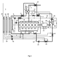
図3は冷却器装置のさらに別の実施例を示している。この場合、第1の冷却回路、第2の冷却回路及び第3の冷却回路が、独立した冷却システムを構成している。冷却剤ポンプ18が第1の冷却回路内で冷却剤を循環させる。この冷却回路は全体が図2の冷却回路と一致する。冷却剤ポンプ44が第2の冷却回路内で冷却剤を循環させる。第2の冷却回路内の冷却剤は、第2のEGR冷却器10内の圧縮空気及び第1の復水器43内の媒体を冷却する。その後この冷却剤は第2の冷却器26内で冷却される。冷却剤ポンプ46が第3の冷却回路内で冷却剤を循環させる。第3の冷却回路内の冷却剤は、第2のEGR冷却器10内の圧縮空気及び第2の復水器45内の媒体を冷却する。その後、冷却剤は第3の冷却器29内で冷却される。
FIG. 3 shows a further embodiment of the cooler device. In this case, the first cooling circuit, the second cooling circuit, and the third cooling circuit constitute an independent cooling system. A
本発明は、図面が参照する実施例のみに限定されず、特許請求の範囲内で自由に変更され得る。
The invention is not limited to the embodiments to which the drawings refer, but may be varied freely within the scope of the claims.
Claims (9)
前記車両が、
圧縮空気を前記燃焼エンジン(2)まで導く入口ライン(8)と、
前記燃焼エンジン(2)内に送られる前に前記圧縮空気を冷却するための第1の給気冷却器(9)及び第2の給気冷却器(10)と、
循環媒体を含むライン回路(32)、前記循環媒体が熱を吸収して蒸発するよう意図された少なくとも1つの熱交換器(9、14、15、34、35)、前記蒸発した媒体が膨張するよう意図されたタービン(37)、及び前記媒体が凝結する温度まで冷却されるよう意図された少なくとも1つの復水器(43)を有するエネルギー回収システムと
を有し、
前記冷却器装置が、
循環冷却剤を冷却するようになされた第1の冷却器(20)を備える第1の冷却回路と、
前記第1の冷却器(20)内で前記冷却剤が冷却される温度より低い温度まで循環冷却剤を冷却するようになされた第2の冷却器(26)を備える第2の冷却回路と
を有している冷却器装置において、
前記第2の冷却器(26)内で前記冷却剤が冷却される温度より低い温度まで循環冷却剤を冷却するようになされた第3の冷却器(29)を備える第3の冷却回路を有しており、前記第3の冷却回路内で冷却された冷却剤が、前記第2の給気冷却器(10)内の前記圧縮空気、及び前記復水器(45)内の前記媒体を冷却するのに使用され、また前記エネルギー回収システムが、前記第1の給気冷却器(9)内の前記圧縮空気から熱エネルギーを吸収するように意図されていること、並びに
前記エネルギー回収システムが2つの復水器(43、45)を含むこと、前記第2の冷却回路内の冷却剤が第1の復水器(43)内の前記媒体を冷却するのに使用されること、及び前記第3の冷却回路内の前記冷却剤が、前記第1の復水器(43)の下流に位置する第2の復水器(45)内の前記媒体を冷却するのに使用されること
を特徴とする冷却器装置。 A cooler device for a vehicle powered by a supercharged combustion engine,
The vehicle
An inlet line (8) for directing compressed air to the combustion engine (2);
A first charge air cooler (9) and a second charge air cooler (10) for cooling the compressed air before being sent into the combustion engine (2);
A line circuit (32) containing a circulating medium, at least one heat exchanger (9, 14, 15, 34, 35) intended for the circulating medium to absorb heat and evaporate, the evaporated medium expands An energy recovery system having a turbine (37) intended to be cooled and at least one condenser (43) intended to be cooled to a temperature at which the medium condenses,
The cooler device is
A first cooling circuit comprising a first cooler (20) adapted to cool the circulating coolant;
A second cooling circuit comprising a second cooler (26) adapted to cool the circulating coolant to a temperature below the temperature at which the coolant is cooled in the first cooler (20). In the cooler device that has
A third cooling circuit comprising a third cooler (29) adapted to cool the circulating coolant to a temperature below the temperature at which the coolant is cooled in the second cooler (26); The coolant cooled in the third cooling circuit cools the compressed air in the second charge air cooler (10) and the medium in the condenser (45). The energy recovery system is intended to absorb thermal energy from the compressed air in the first charge air cooler (9) , and
The energy recovery system includes two condensers (43, 45), and a coolant in the second cooling circuit is used to cool the medium in the first condenser (43). And the coolant in the third cooling circuit cools the medium in the second condenser (45) located downstream of the first condenser (43). A cooler device characterized in that it is used .
Applications Claiming Priority (3)
| Application Number | Priority Date | Filing Date | Title |
|---|---|---|---|
| SE1050516A SE535877C2 (en) | 2010-05-25 | 2010-05-25 | Cooling arrangement of a vehicle driven by a supercharged internal combustion engine |
| SE1050516-2 | 2010-05-25 | ||
| PCT/SE2011/050593 WO2011149409A1 (en) | 2010-05-25 | 2011-05-11 | Cooler arrangement for a vehicle powered by a supercharged combustion engine |
Publications (2)
| Publication Number | Publication Date |
|---|---|
| JP2013526682A JP2013526682A (en) | 2013-06-24 |
| JP5596855B2 true JP5596855B2 (en) | 2014-09-24 |
Family
ID=45004187
Family Applications (1)
| Application Number | Title | Priority Date | Filing Date |
|---|---|---|---|
| JP2013512574A Expired - Fee Related JP5596855B2 (en) | 2010-05-25 | 2011-05-11 | Cooler device for a vehicle powered by a supercharged combustion engine |
Country Status (9)
| Country | Link |
|---|---|
| US (1) | US8584457B2 (en) |
| EP (1) | EP2577016B1 (en) |
| JP (1) | JP5596855B2 (en) |
| KR (1) | KR101780367B1 (en) |
| CN (1) | CN103237967B (en) |
| BR (1) | BR112012026562A2 (en) |
| RU (1) | RU2524479C1 (en) |
| SE (1) | SE535877C2 (en) |
| WO (1) | WO2011149409A1 (en) |
Families Citing this family (51)
| Publication number | Priority date | Publication date | Assignee | Title |
|---|---|---|---|---|
| DE102009028467A1 (en) * | 2009-08-12 | 2011-02-17 | Robert Bosch Gmbh | Device for using waste heat |
| EP2593645B1 (en) * | 2010-07-14 | 2020-05-06 | Mack Trucks, Inc. | Waste heat recovery system with partial recuperation |
| US8813489B2 (en) * | 2011-02-15 | 2014-08-26 | Deere & Company | Internal combustion engine charge air cooler precooler |
| GB2493741B (en) * | 2011-08-17 | 2017-02-22 | Gm Global Tech Operations Llc | Exhaust gas recirculation system for an internal combustion engine |
| US9803548B2 (en) * | 2012-04-02 | 2017-10-31 | Powerphase Llc | Gas turbine efficiency and regulation speed improvements using supplementary air system continuous and storage systems and methods of using the same |
| DE102012209811A1 (en) | 2012-06-12 | 2013-12-12 | Bayerische Motoren Werke Aktiengesellschaft | Drive system for vehicle, has main pump that supplies coolant into coolant circuit, where coolant circuit has adjusting part, with which entry of coolant in one of two lines is controlled or regulated |
| DE102012209808A1 (en) | 2012-06-12 | 2013-12-12 | Bayerische Motoren Werke Aktiengesellschaft | Propulsion system for vehicle, has main pump whose intake unit is arranged in spacer and slot, and mixing point arranged in upstream of cooling device and located in another spacer to form partial mass flow |
| DE102012209813A1 (en) | 2012-06-12 | 2013-12-12 | Bayerische Motoren Werke Aktiengesellschaft | Drive system for vehicle, is formed for distribution of fluid mass flow in refrigerant circuit downstream to cooling unit in partial mass flow and in another partial mass flow guided in mixing position in line |
| DE102012216452A1 (en) * | 2012-09-14 | 2014-03-20 | Eberspächer Exhaust Technology GmbH & Co. KG | Heat exchanger |
| US9017217B2 (en) | 2012-11-08 | 2015-04-28 | Ford Global Technologies, Llc | Pilot downshifting system and method |
| DE102013205648A1 (en) * | 2012-12-27 | 2014-07-03 | Robert Bosch Gmbh | System for energy recovery from a waste heat stream of an internal combustion engine |
| US8813691B1 (en) | 2013-02-18 | 2014-08-26 | Shawn Grannell | High efficiency, ternary mix engine |
| RU2544115C1 (en) * | 2013-08-23 | 2015-03-10 | Николай Борисович Болотин | Internal combustion engine with heat recovery |
| RU2531460C1 (en) * | 2013-09-27 | 2014-10-20 | Николай Борисович Болотин | Internal combustion engine with heat regeneration |
| US9587546B2 (en) * | 2013-10-02 | 2017-03-07 | Ford Global Technologies, Llc | Methods and systems for hybrid vehicle waste heat recovery |
| JP2015086778A (en) * | 2013-10-30 | 2015-05-07 | いすゞ自動車株式会社 | Engine cooling system |
| JP2015086779A (en) * | 2013-10-30 | 2015-05-07 | いすゞ自動車株式会社 | Engine cooling system |
| KR101601088B1 (en) * | 2013-12-23 | 2016-03-09 | 현대자동차주식회사 | Engine Cooling System |
| US20150198082A1 (en) * | 2014-01-16 | 2015-07-16 | GM Global Technologies Operations LLC | Turbocharged Internal Combustion Engine With Pre-Charge Air Cooler |
| JP6194274B2 (en) * | 2014-04-04 | 2017-09-06 | 株式会社神戸製鋼所 | Waste heat recovery system and waste heat recovery method |
| JP6194273B2 (en) * | 2014-04-04 | 2017-09-06 | 株式会社神戸製鋼所 | Waste heat recovery device and waste heat recovery method |
| KR101575254B1 (en) * | 2014-05-20 | 2015-12-07 | 현대자동차 주식회사 | Cooling and thermoelectric power generating system for vehicle |
| US10378390B2 (en) * | 2014-06-26 | 2019-08-13 | Volvo Truck Corporation | Internal combustion engine system with heat recovery |
| EP3161275B1 (en) * | 2014-06-26 | 2018-12-19 | Volvo Truck Corporation | A waste heat recovery device |
| JP6342755B2 (en) * | 2014-09-05 | 2018-06-13 | 株式会社神戸製鋼所 | Compression device |
| DE102014220334A1 (en) * | 2014-10-07 | 2016-04-07 | Krones Aktiengesellschaft | Food processing plant, in particular brewery plant with cogeneration |
| DE102014017245A1 (en) * | 2014-11-20 | 2016-06-09 | Man Truck & Bus Ag | Cooling system for a vehicle, in particular for a commercial vehicle |
| DE102014017244A1 (en) * | 2014-11-20 | 2016-06-09 | Man Truck & Bus Ag | Cooling system for a vehicle, in particular for a commercial vehicle |
| SE538836C2 (en) * | 2014-12-05 | 2016-12-20 | Scania Cv Ab | A cooling arrangement for a WHR-system |
| US9863306B2 (en) * | 2015-01-26 | 2018-01-09 | Delphi Technologies, Inc. | Engine restart aid |
| KR102403512B1 (en) | 2015-04-30 | 2022-05-31 | 삼성전자주식회사 | Outdoor unit of air conditioner, control device applying the same |
| US10202888B2 (en) * | 2015-12-08 | 2019-02-12 | Ford Global Technologies, Llc | Engine air path cooling system |
| DE112015007098T5 (en) | 2015-12-21 | 2018-08-02 | Cummins Inc. | INTEGRATED CONTROL SYSTEM FOR ENGINE HEAT RECOVERY USING AN ORGANIC RANKINE CYCLE |
| SE540089C2 (en) * | 2016-07-07 | 2018-03-20 | Scania Cv Ab | A cooling system in a hybrid vehicle |
| SE540324C2 (en) * | 2016-10-28 | 2018-06-26 | Scania Cv Ab | A cooling system for cooling a combustion engine and a WHR system |
| DE102016014904A1 (en) * | 2016-12-15 | 2018-06-21 | Deutz Aktiengesellschaft | Internal combustion engine |
| SE542064C2 (en) * | 2017-06-07 | 2020-02-18 | Scania Cv Ab | A cooling system for a combustion engine and a WHR system |
| DE102017011851A1 (en) * | 2017-12-21 | 2019-06-27 | Daimler Ag | Arrangement for converting thermal energy from heat loss of an internal combustion engine |
| DE102017011844A1 (en) * | 2017-12-21 | 2019-06-27 | Daimler Ag | Arrangement for converting thermal energy from heat loss of an internal combustion engine |
| US20190234343A1 (en) * | 2018-01-30 | 2019-08-01 | International Engine Intellectual Property Company, Llc. | Organic rankine cycle waste heat recovery system having two loops |
| FR3079558B1 (en) * | 2018-03-27 | 2023-11-03 | Renault Sas | COOLING CIRCUIT FOR AN INTERNAL COMBUSTION ENGINE EQUIPPED WITH AN EXHAUST GAS RECIRCULATION CIRCUIT AND ITS CONTROL METHOD |
| DE102018107388B4 (en) * | 2018-03-28 | 2019-12-24 | Iav Gmbh Ingenieurgesellschaft Auto Und Verkehr | Internal combustion engine with evaporative cooling and waste heat utilization |
| DE102018113395A1 (en) * | 2018-06-06 | 2019-12-12 | Man Energy Solutions Se | Cooling system of an internal combustion engine |
| US10830122B2 (en) | 2018-10-29 | 2020-11-10 | Fca Us Llc | Intake and charge air cooling system |
| US11124047B2 (en) | 2018-11-03 | 2021-09-21 | Hyundai Motor Company | Vehicular HVAC system with liquid-cooled charge air cooler integration |
| KR102079584B1 (en) | 2019-04-30 | 2020-02-20 | 김영재 | Cooking container that can expand function |
| FR3101917B1 (en) * | 2019-10-09 | 2022-07-15 | Ifp Energies Now | Single radiator cooling system |
| EP4155518B1 (en) * | 2020-03-23 | 2024-05-01 | Cummins, Inc. | Multi-core heat recovery charge cooler |
| AT524156B1 (en) * | 2020-08-04 | 2022-07-15 | Man Truck & Bus Se | Device for energy recovery with a waste heat recovery cycle |
| KR20220080556A (en) * | 2020-12-07 | 2022-06-14 | 현대자동차주식회사 | Integrated thermal management system for vehicle |
| US11680515B1 (en) | 2022-03-31 | 2023-06-20 | Fca Us Llc | Intake and charge air cooling system with passive variable charge enabler |
Family Cites Families (23)
| Publication number | Priority date | Publication date | Assignee | Title |
|---|---|---|---|---|
| US3888084A (en) * | 1974-05-20 | 1975-06-10 | Gilbert L Hawkins | Thermal recovery system |
| CH627524A5 (en) * | 1978-03-01 | 1982-01-15 | Sulzer Ag | METHOD AND SYSTEM FOR THE USE OF HEAT THROUGH THE EXTRACTION OF HEAT FROM AT LEAST ONE FLOWING HEAT CARRIER. |
| CH632051A5 (en) * | 1978-10-25 | 1982-09-15 | Sulzer Ag | INTERNAL COMBUSTION ENGINE. |
| FR2449780A1 (en) * | 1979-02-22 | 1980-09-19 | Semt | METHOD AND APPARATUS FOR RECOVERING THERMAL ENERGY IN A SUPERFUELED INTERNAL COMBUSTION ENGINE |
| JPS61151039U (en) * | 1985-03-11 | 1986-09-18 | ||
| FR2757903B1 (en) * | 1996-12-31 | 1999-03-26 | New Sulzer Diesel France Sa | METHOD AND APPARATUS FOR RECOVERING HEAT IN COMBUSTION AIR OF AN ENGINE |
| DE19854544B4 (en) * | 1998-11-26 | 2004-06-17 | Mtu Friedrichshafen Gmbh | Cooling system for a supercharged internal combustion engine |
| DE10335567A1 (en) * | 2003-07-31 | 2005-03-10 | Behr Gmbh & Co Kg | Circuit arrangement for cooling charge air and method for operating such a circuit arrangement |
| DE102004024289A1 (en) * | 2004-05-15 | 2005-12-15 | Deere & Company, Moline | Cooling system for a vehicle |
| ATE454543T1 (en) * | 2004-12-23 | 2010-01-15 | Valeo Thermique Moteur Sa | SYSTEM FOR CONTROLLING THE THERMAL ENERGY OF A MOTOR VEHICLE ENGINE BY ADJUSTING THE SYSTEM'S FLUID DRIVES |
| EP1902198A2 (en) * | 2005-06-16 | 2008-03-26 | UTC Power Corporation | Organic rankine cycle mechanically and thermally coupled to an engine driving a common load |
| DE102005042396A1 (en) * | 2005-09-06 | 2007-03-15 | Behr Gmbh & Co. Kg | Cooling system for a motor vehicle |
| US20090020079A1 (en) * | 2005-11-10 | 2009-01-22 | BEHRmbH & Co. KG | Circulation system, mixing element |
| DE102006028868B4 (en) * | 2006-06-23 | 2017-07-13 | Man Truck & Bus Ag | Charged internal combustion engine with an expander unit in a heat recovery cycle |
| DE102006044820B4 (en) * | 2006-09-20 | 2019-03-07 | MAN Truck & Bus Österreich AG | Cooling system of an internal combustion engine with charge air supply |
| EP2066884B1 (en) * | 2006-09-22 | 2011-08-24 | Renault Trucks | Cooling circuit for the thermal engine of an automotive vehicle |
| DE102008014169A1 (en) * | 2007-04-26 | 2009-01-08 | Behr Gmbh & Co. Kg | Heat exchanger, in particular for exhaust gas cooling, system with a heat exchanger for exhaust gas cooling, method for operating a heat exchanger |
| US20090078220A1 (en) * | 2007-09-25 | 2009-03-26 | Ford Global Technologies, Llc | Cooling System with Isolated Cooling Circuits |
| DE102007052117A1 (en) * | 2007-10-30 | 2009-05-07 | Voith Patent Gmbh | Powertrain, especially for trucks and rail vehicles |
| AT507096B1 (en) * | 2008-12-10 | 2010-02-15 | Man Nutzfahrzeuge Oesterreich | DRIVE UNIT WITH COOLING CIRCUIT AND SEPARATE HEAT RECOVERY CIRCUIT |
| DE102009006959B4 (en) * | 2009-01-31 | 2020-03-12 | Modine Manufacturing Co. | Energy recovery system |
| ATE556887T1 (en) * | 2010-02-12 | 2012-05-15 | Fiat Ricerche | MOTOR VEHICLE HAVING AN AUXILIARY COOLING SYSTEM WITH ONE OR MORE RADIATORS FORMED BY VEHICLE BODY COMPONENTS |
| CN102191991A (en) * | 2010-03-03 | 2011-09-21 | 株式会社电装 | Controller for engine cooling system |
-
2010
- 2010-05-25 SE SE1050516A patent/SE535877C2/en unknown
-
2011
- 2011-05-11 CN CN201180025439.4A patent/CN103237967B/en not_active Expired - Fee Related
- 2011-05-11 RU RU2012156162/06A patent/RU2524479C1/en not_active IP Right Cessation
- 2011-05-11 KR KR1020127033325A patent/KR101780367B1/en active IP Right Grant
- 2011-05-11 US US13/699,319 patent/US8584457B2/en not_active Expired - Fee Related
- 2011-05-11 JP JP2013512574A patent/JP5596855B2/en not_active Expired - Fee Related
- 2011-05-11 EP EP11786985.9A patent/EP2577016B1/en active Active
- 2011-05-11 BR BR112012026562A patent/BR112012026562A2/en not_active Application Discontinuation
- 2011-05-11 WO PCT/SE2011/050593 patent/WO2011149409A1/en active Application Filing
Also Published As
| Publication number | Publication date |
|---|---|
| SE1050516A1 (en) | 2011-11-26 |
| RU2524479C1 (en) | 2014-07-27 |
| EP2577016A4 (en) | 2018-01-24 |
| EP2577016A1 (en) | 2013-04-10 |
| US20130068202A1 (en) | 2013-03-21 |
| CN103237967A (en) | 2013-08-07 |
| WO2011149409A1 (en) | 2011-12-01 |
| CN103237967B (en) | 2016-02-10 |
| KR20130081664A (en) | 2013-07-17 |
| KR101780367B1 (en) | 2017-09-21 |
| BR112012026562A2 (en) | 2016-07-12 |
| US8584457B2 (en) | 2013-11-19 |
| SE535877C2 (en) | 2013-01-29 |
| EP2577016B1 (en) | 2019-02-27 |
| JP2013526682A (en) | 2013-06-24 |
| RU2012156162A (en) | 2014-06-27 |
Similar Documents
| Publication | Publication Date | Title |
|---|---|---|
| JP5596855B2 (en) | Cooler device for a vehicle powered by a supercharged combustion engine | |
| EP2678548B1 (en) | System for converting thermal energy to mechanical energy in a vehicle | |
| US8490392B2 (en) | Arrangement for a supercharged combustion engine concerning coolers for inlet air to and exhaust gases from the engine | |
| JP5481737B2 (en) | Waste heat utilization device for internal combustion engine | |
| JP4718745B2 (en) | Improved heat pump device for regulating automotive temperature | |
| US20130219872A1 (en) | Thermoelectric recovery and peltier heating of engine fluids | |
| KR20110026477A (en) | Arrangement for a supercharged combustion engine | |
| JP5001465B2 (en) | Cooling device for recirculated exhaust gas in a combustion engine | |
| CN110439666B (en) | Engine cooling system with two thermostats, including a closed circuit in a rankine cycle | |
| JP5475924B2 (en) | Device for cooling compressed air and / or recirculated exhaust gas sent to an internal combustion engine | |
| JP2013160076A (en) | Rankine cycle device |
Legal Events
| Date | Code | Title | Description |
|---|---|---|---|
| A529 | Written submission of copy of amendment under section 34 (pct) |
Free format text: JAPANESE INTERMEDIATE CODE: A529 Effective date: 20121122 |
|
| A621 | Written request for application examination |
Free format text: JAPANESE INTERMEDIATE CODE: A621 Effective date: 20121122 |
|
| A131 | Notification of reasons for refusal |
Free format text: JAPANESE INTERMEDIATE CODE: A131 Effective date: 20131008 |
|
| A601 | Written request for extension of time |
Free format text: JAPANESE INTERMEDIATE CODE: A601 Effective date: 20140108 |
|
| A602 | Written permission of extension of time |
Free format text: JAPANESE INTERMEDIATE CODE: A602 Effective date: 20140116 |
|
| A521 | Written amendment |
Free format text: JAPANESE INTERMEDIATE CODE: A523 Effective date: 20140207 |
|
| TRDD | Decision of grant or rejection written | ||
| A01 | Written decision to grant a patent or to grant a registration (utility model) |
Free format text: JAPANESE INTERMEDIATE CODE: A01 Effective date: 20140711 |
|
| A61 | First payment of annual fees (during grant procedure) |
Free format text: JAPANESE INTERMEDIATE CODE: A61 Effective date: 20140807 |
|
| R150 | Certificate of patent or registration of utility model |
Ref document number: 5596855 Country of ref document: JP Free format text: JAPANESE INTERMEDIATE CODE: R150 |
|
| LAPS | Cancellation because of no payment of annual fees |