JP5595116B2 - Sheet processing apparatus and image forming apparatus - Google Patents
Sheet processing apparatus and image forming apparatus Download PDFInfo
- Publication number
- JP5595116B2 JP5595116B2 JP2010113293A JP2010113293A JP5595116B2 JP 5595116 B2 JP5595116 B2 JP 5595116B2 JP 2010113293 A JP2010113293 A JP 2010113293A JP 2010113293 A JP2010113293 A JP 2010113293A JP 5595116 B2 JP5595116 B2 JP 5595116B2
- Authority
- JP
- Japan
- Prior art keywords
- sheet
- folding roller
- folding
- sheet bundle
- unit
- Prior art date
- Legal status (The legal status is an assumption and is not a legal conclusion. Google has not performed a legal analysis and makes no representation as to the accuracy of the status listed.)
- Active
Links
- 238000012545 processing Methods 0.000 title claims description 43
- 230000005540 biological transmission Effects 0.000 claims description 38
- 238000000034 method Methods 0.000 claims description 12
- 238000010586 diagram Methods 0.000 description 8
- 230000015572 biosynthetic process Effects 0.000 description 7
- 238000012546 transfer Methods 0.000 description 7
- 238000004140 cleaning Methods 0.000 description 2
- 238000001514 detection method Methods 0.000 description 2
- 239000011521 glass Substances 0.000 description 2
- 244000126211 Hericium coralloides Species 0.000 description 1
- 239000000853 adhesive Substances 0.000 description 1
- 230000001070 adhesive effect Effects 0.000 description 1
- 238000005452 bending Methods 0.000 description 1
- 238000004891 communication Methods 0.000 description 1
- 238000012544 monitoring process Methods 0.000 description 1
- 238000004080 punching Methods 0.000 description 1
Images


Classifications
-
- B—PERFORMING OPERATIONS; TRANSPORTING
- B65—CONVEYING; PACKING; STORING; HANDLING THIN OR FILAMENTARY MATERIAL
- B65H—HANDLING THIN OR FILAMENTARY MATERIAL, e.g. SHEETS, WEBS, CABLES
- B65H45/00—Folding thin material
- B65H45/12—Folding articles or webs with application of pressure to define or form crease lines
- B65H45/18—Oscillating or reciprocating blade folders
Description
本発明は、シート処理装置及び画像形成装置に関し、特にシートを折り曲げる折り曲げ部の構成に関する。 The present invention relates to a sheet processing apparatus and an image forming apparatus, and more particularly to a configuration of a bending portion that bends a sheet.
従来、複写機、レーザービームプリンタ、ファクシミリ及びこれらの複合機等の電子写真方式の画像形成装置においては、シート上にトナー画像を形成する画像形成部と、シート上に形成されたトナー画像を定着させる定着部とを備えている。さらに、画像形成装置においては、トナー画像が定着されたシートに対して製本処理等の処理を行うシート処理装置を設けたものがある。 2. Description of the Related Art Conventionally, in an electrophotographic image forming apparatus such as a copying machine, a laser beam printer, a facsimile machine, or a combination of these, an image forming unit that forms a toner image on a sheet and a toner image formed on the sheet are fixed. And a fixing unit to be provided. Further, some image forming apparatuses are provided with a sheet processing apparatus that performs a bookbinding process or the like on a sheet on which a toner image is fixed.
ここで、従来のシート処理装置においては、製本処理の際、所定枚数のシートを重ねてシート束を形成した後、シート束の中央部を、糸やステイプル、接着剤等で綴じた後、綴じ部を二つ折りすることでシート束を冊子状に形成するものが一般的に知られている。なお、このような従来のシート処理装置としては、製本処理を行うため、突き板と折りローラ対を備えたものがある(特許文献1参照)。そして、シートを二つ折りする場合は、突き板によって折りローラ対のニップ部に、シート束の綴じ部を押し込むことにより、綴じ部を二つ折りするようにしている。 Here, in the conventional sheet processing apparatus, in the bookbinding process, after a predetermined number of sheets are stacked to form a sheet bundle, the center portion of the sheet bundle is bound with a thread, staple, adhesive, or the like, and then bound. It is generally known that a sheet bundle is formed into a booklet by folding the part in half. Such a conventional sheet processing apparatus includes a veneer and a pair of folding rollers in order to perform bookbinding (see Patent Document 1). When the sheet is folded in half, the binding portion is folded in half by pushing the binding portion of the sheet bundle into the nip portion of the pair of folding rollers by the thrust plate.
ところで、このような従来のシート処理装置においては、折りローラ対を駆動する駆動伝達部を折りローラ対の回転軸の片側に設けた、いわゆる片側駆動の駆動伝達系を有するものがある。このような駆動伝達部においては、モータ等の駆動源からの駆動を複数のギアを介して折りローラ対に伝達する機構が採用されている。このように、ギアとギアとの間で駆動伝達することで折りローラ対の駆動伝達部側端にはニップ圧を増大させる方向の力が生じる。このため、折りローラ対の駆動伝達部側と、駆動伝達部側の反対側との間でニップ圧のアンバランスが生ずる。 By the way, some of such conventional sheet processing apparatuses have a so-called one-side drive transmission system in which a drive transmission unit for driving the pair of folding rollers is provided on one side of the rotation shaft of the pair of folding rollers. Such a drive transmission unit employs a mechanism that transmits the drive from a drive source such as a motor to the pair of folding rollers via a plurality of gears. Thus, by transmitting the drive between the gears, a force in the direction of increasing the nip pressure is generated at the end of the folding roller pair on the side of the drive transmission unit. For this reason, an unbalance of the nip pressure occurs between the drive transmission unit side of the folding roller pair and the opposite side of the drive transmission unit side.
また、このような片側駆動の折りローラ対では、ニップ圧の高い駆動伝達部側の搬送効率が、ニップ圧の低い駆動伝達部側の反対側よりも高くなる。そして、このような折りローラ対でシート束を二つ折りにしながら搬送すると、搬送されるシート束は、搬送効率が高い駆動伝達部側の方が先に進んでしまい、斜行されてしまう。 Further, in such a one-side driven folding roller pair, the conveyance efficiency on the side of the drive transmission unit having a high nip pressure is higher than that on the side opposite to the drive transmission unit having a low nip pressure. When the sheet bundle is conveyed while being folded in half by such a pair of folding rollers, the conveyed sheet bundle is advanced on the side of the drive transmission unit having higher conveyance efficiency and is skewed.
そこで、本発明は、このような現状に鑑みてなされたものであり、シート束を斜行することなく、良好に二つ折りしながら搬送することのできるシート処理装置及び画像形成装置を提供することを目的とするものである。 Therefore, the present invention has been made in view of such a current situation, and provides a sheet processing apparatus and an image forming apparatus that can be conveyed while being folded in a good manner without skewing a sheet bundle. It is intended.
本発明は、シート束を二つ折りするシート処理装置において、搬送されてくるシートを順次積載するシート積載手段と、シート束を二つ折りしながら搬送する折りローラ対と、前記シート積載手段に積載されたシート束を前記折りローラ対のニップ部に押し込む突き部材と、前記折りローラ対を駆動する駆動部と、前記折りローラ対のシート束搬送方向と直交する幅方向の一方の側端側に設けられ、前記折りローラ対を構成する第1折りローラ及び第2折りローラのそれぞれに対し、前記第1折りローラ及び前記第2折りローラが圧接する方向に力を発生させながら前記駆動部からの駆動を伝達する駆動伝達部と、を備え、前記シート積載手段に積載されたシート束の駆動伝達部側とは反対側の幅方向側端部から先に前記折りローラ対のニップ部に押し込まれるように、前記突き部材の押し込み端を、前記駆動伝達部側とは反対側が、前記駆動伝達部側よりも押し込み方向下流側に位置するように傾斜させることを特徴とするものである。 The present invention provides a sheet processing apparatus for folding a sheet bundle in half, a sheet stacking means for sequentially stacking conveyed sheets, a pair of folding rollers for transporting the sheet bundle while folding in half, and the sheet stacking means stacked on the sheet stacking means. A pushing member that pushes the bundle of sheets into the nip portion of the pair of folding rollers, a driving unit that drives the pair of folding rollers, and one side end in the width direction perpendicular to the sheet bundle conveyance direction of the pair of folding rollers. And driving from the drive unit while generating a force in a direction in which the first folding roller and the second folding roller are pressed against each of the first folding roller and the second folding roller constituting the pair of folding rollers. the provided a drive transmission portion which heat is reached, the previous SL of the pair of folding rollers above the widthwise side end portion opposite to the drive transmission portion of the sheet bundle stacked on the sheet stacking means Stevenage The pushing end of the thrust member is inclined so that the opposite side to the drive transmission part side is located on the downstream side in the push direction with respect to the drive transmission part side so as to be pushed into the part. is there.
本発明のように、折りローラ対の駆動伝達部側とは反対側のシート束の幅方向側端部から先に折りローラ対のニップ部に押し込むようにすることにより、シート束を斜行することなく、良好に二つ折りしながら搬送することができる。 As in the present invention, the sheet bundle is skewed by being pushed into the nip portion of the folding roller pair first from the width direction end of the sheet bundle opposite to the drive transmission portion side of the folding roller pair. And can be conveyed while being folded in two.
以下、本発明を実施するための形態を、図面を用いて詳細に説明する。図1は、本発明の実施の形態に係るシート処理装置を備えた画像形成装置の構成を示す図である。図1において、900は画像形成装置、900Aは画像形成装置本体(以下、装置本体という)である。装置本体900Aには、スキャナユニット955及びイメージセンサ954を備えたイメージリーダ(画像読取装置)951、シートに画像を形成する画像形成部902、両面装置953等が設けられている。また、装置本体900Aの上面には、原稿を不図示のプラテンガラスに給送する原稿給送装置950が設けられている。
DESCRIPTION OF EMBODIMENTS Hereinafter, embodiments for carrying out the present invention will be described in detail with reference to the drawings. FIG. 1 is a diagram illustrating a configuration of an image forming apparatus including a sheet processing apparatus according to an embodiment of the present invention. In FIG. 1, 900 is an image forming apparatus, and 900A is an image forming apparatus main body (hereinafter referred to as apparatus main body). The apparatus
画像形成部902には、円筒状の感光体ドラム906、帯電器907、現像器909、クリーニング装置913等がそれぞれ備えられており、さらに画像形成部902の下流側には定着装置912、排出ローラ対914等が配設されている。また、この装置本体900Aには、装置本体900Aから、画像形成後、排出される画像形成済みのシートを処理するシート処理装置であるフィニッシャ100が接続されている。なお、206は装置本体900A及びフィニッシャ100の制御を司る制御部であるCPU回路部である。
The
次に、このような構成の装置本体900Aの画像形成動作について説明する。CPU回路部206から画像形成信号が出力されると、まず原稿給送装置950によりプラテンガラス上に原稿が載置され、この原稿の画像がイメージリーダ951により読み取られ、読み取られたデジタルデータは露光手段908に入力される。そして、露光手段908により、このデジタルデータに応じた光が感光体ドラム906に照射される。このとき、感光体ドラム906の表面は帯電器907により一様に帯電されており、このように光が照射されると、感光体ドラム表面に静電潜像が形成され、この静電潜像を現像器909により現像することにより、感光体ドラム表面にトナー像が形成される。
Next, an image forming operation of the apparatus
一方、CPU回路部206から給紙信号が出力されると、まずカセット902a〜902d、及び給紙デッキ902eにセットされたシートPが給紙ローラ903a〜903e、搬送ローラ対904によってレジストローラ910まで搬送される。次に、シートPは、レジストローラ910によってシート先端と感光体ドラム上のトナー像の先端を合わせるようなタイミングで転写帯電器905を備えた転写部まで搬送される。そして、この転写部において、シートPに転写バイアスが転写帯電器905により印加されることにより、感光体ドラム上のトナー像がシート側に転写される。
On the other hand, when a paper feed signal is output from the
次に、トナー像が転写されたシートPは、搬送ベルト911によって定着装置912まで搬送され、定着装置912を通過する際にトナー像が熱定着される。この時、感光体ドラム上ではシートPに転写されずに付着している残存トナー等の異物がクリーニング装置913により掻き落とされており、この結果、感光体ドラム906の表面がクリアーとなり、次の画像形成に備えることができる。
Next, the sheet P to which the toner image has been transferred is conveyed to the
次に、定着装置912によりトナー像が熱定着されたシートは、そのまま排出ローラ対914によりフィニッシャ100に搬送される。なお、シートPの両面に画像を形成する場合は、トナー像が熱定着された後、シートPは切換部材915により両面装置953に搬送され、画像形成される面を反転して再度、画像形成部902に向かい、裏面に画像が形成される。そして、この後、排出ローラ対914によりフィニッシャ100に搬送される。
Next, the sheet on which the toner image has been thermally fixed by the
フィニッシャ100は、装置本体900Aから排出されたシートを順に取り込み、取り込んだ複数のシートを整合して1つの束に束ねる処理、取り込んだシートの後端付近に孔をあけるパンチ処理を行うようになっている。また、フィニッシャ100はシート束後端側をステイプルするステイプル処理、製本処理等の処理を行うようになっており、図2に示すように、シートをステイプルするステイプル部700及びシート束を二つ折りにして製本する中綴じ製本部800を備えている。
The
そして、フィニッシャ100は、シートを装置内部に取り込むための入口ローラ対102を備えており、装置本体900Aから排紙されたシートは、入口ローラ対102に受け渡される。なお、この時、入口センサ101によりシートの受渡しタイミングも同時に検知される。
The
この後、入口ローラ対102により搬送されたシートは搬送パス103を通過しながら、シートの端部位置を横レジ検知センサ104により検知され、フィニッシャ100のセンター(中央)位置に対してどの程度、幅方向のずれが生じているかが検知される。また、このように幅方向のずれ(以下、横レジ誤差という)が検知された後、シートはシフトローラ対105,106に搬送されている途中で不図示のシフトユニットが手前方向、或は奥方向に所定量移動することにより、シートのシフト動作が実施される。
Thereafter, the sheet conveyed by the
次に、シートは搬送ローラ対110により搬送され、バッファローラ対115に達する。この後、上トレイ136に排紙される場合は、上パス切換部材118が不図示のソレノイド等の駆動手段により、図中破線の状態になる。これにより、シートは上パス搬送路117に導かれ、上排紙ローラ120により上トレイ136に排出される。
Next, the sheet is conveyed by the conveying
上トレイ136に排出されない場合は、バッファローラ対115により搬送されたシートは、実線に示す状態の上パス切換部材118により束搬送パス121に導かれ、この後、搬送ローラ122、束搬送ローラ対124により順次搬送パス内を通過していく。次に、搬送されてきたシートを下方の積載トレイ137に排出する場合は、シートは、まず実線に示す状態のサドルパス切換部材125により下パス126に搬送され、この後、下排紙ローラ対128により中間処理トレイ138に排出される。
When the sheet is not discharged to the
そして、排出されたシートを、パドル131やベルトローラ129等の戻し手段により、順次積載しながら整合することにより、整合積載されたシート束に対して処理を施すためのシート積載部としての中間処理トレイ上で所定枚数のシートが整合処理される。次に、このように中間処理トレイ上で整合処理されたシート束は、必要に応じてステイプラ132により綴じ処理が施され、この後、束排出ローラ対130により下方の積載トレイ137に排紙される。
Then, the discharged sheets are aligned while being sequentially stacked by the return means such as the
一方、シートをサドル(中綴じ)処理する場合には、不図示のソレノイド等の駆動手段によりサドルパス切換部材125を破線で示す位置に移動させる。これにより、シートがサドルパス133に搬送され、サドル入口ローラ対134により中綴じ製本部800に導かれる。
On the other hand, when the sheet is subjected to saddle (saddle stitching) processing, the saddle
次に、シートは、図3の(a)に示すように、サイズに応じてソレノイドにより動作する切換部材125bにより搬入口を選択されて、シート積載手段としての処理トレイ155内に搬入される。ここで、このようにサドル入口ローラ対134から排紙されたシートが処理トレイ155の開放空間に排紙されることで、シートまたはシート束の先端が先端ストッパ147に搬送され、シート搬送方向先端位置の整合が行われる。また、開放空間に排紙されたシートは、必要に応じて送りローラ144により先端ストッパ147に送り込まれる。ここで、先端ストッパ147は、シートサイズ(シートの搬送方向の長さ)に応じて、搬送されるシート搬送方向長さの半分の距離で、ステイプラ中心Cの位置から下方に待機している。このため、処理トレイ155に積載されたシートは、シート中心がステイプル位置に合うようになっている。
Next, as shown in FIG. 3A, the sheet is loaded into a
なお、このような1枚目のシートの収納が終了すると、次に2枚目のシートが処理トレイ155に排紙される。ここで、このように排紙される2枚目のシートSは、図3の(b)に示すように、切換部材125bよりも上方に位置する切換部材125aによって処理トレイ155に搬送される。なお、このように切換部材125a,125bによってシートPの処理トレイ155に搬送される経路を切り換えることにより、既積載シートの後端と搬送されて来るシートの先端が衝突するのを防ぐことができる。この様にして、製本される枚数だけシートが処理トレイ155に搬送されてシート束の積載が完了する。
When the storage of the first sheet is completed, the second sheet is discharged to the
処理トレイ155の途中位置には、処理トレイ155を挟んで対向配置され、処理トレイ155に収納された複数枚のシートからなる束の搬送方向中央部を綴じる綴じ手段であるステイプラ142が設けられている。このステイプラ142はシートの収納が完了すると、そのシートからなるシート束の搬送方向中央部を針綴じする。
In the middle of the
ステイプラ142の下流側には、処理トレイ155に収納されたシート束を搬送方向中央部で2つ折りする折り部を構成する第1〜第3折りローラ対148〜150と、突き板146が、処理トレイ155を挟んで対向するように設けられている。この突き板146は、処理トレイ155に収納されたシート束の搬送方向中央部に向けて突出するものである。
On the downstream side of the
そして、綴じられたシート束を折り畳む場合は、ステイプル処理終了後、先端ストッパ147を下降させ、シート束のステイプル位置(シート束搬送方向中央部)が第1折りローラ対148のニップ位置となるように、ステイプル位置にあるシート束を移動させる。この後、図3に示す矢印方向に突き部材である突き板146を突き出すことにより、シート束を第1折りローラ対148のニップ部に押し込みながら、シート束を中央部で2つ折りに折り畳むことができる。なお、綴じ処理を行わずにシート束を折り畳む場合は、処理トレイ155に収納されたシート束の搬送方向中央部が第1折りローラ対148のニップ位置となるように、シート束を移動させた後、突き板146を突き出すようにする。次に、第1折りローラ対148により2つ折りされたシート束は、第2折りローラ対149、第3折りローラ対150により、シート束の折り曲げ端部を押し潰された後、図2に示すサドル排紙ローラ対152によりサドルトレイ153に積載される。
When folding the bound sheet bundle, after the stapling process is finished, the leading
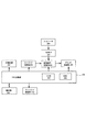
図4は画像形成装置600及びフィニッシャ100を制御する制御ブロック図である。図4に示すように、CPU回路部206は、不図示のCPU、ROM207、RAM208を有している。CPU回路部206は、DF(原稿給送装置)制御部202、イメージリーダ制御部203、画像信号制御部204、プリンタ制御部205、フィニッシャ制御部210、外部インターフェイス201を制御している。なお、CPU回路部206は、ROM207に格納されているプログラム及び操作部209の設定に従って制御する。
FIG. 4 is a control block diagram for controlling the image forming apparatus 600 and the
DF(原稿給送装置)制御部202は、原稿給送装置950を制御するものであり、イメージリーダ制御部203はイメージリーダを制御する。プリンタ制御部205は装置本体900Aを制御するものであり、フィニッシャ制御部210はフィニッシャ100(ステイプル部700及び中綴じ製本部800)を制御する。なお、本実施の形態において、フィニッシャ制御部210をフィニッシャ100に搭載した構成について説明する。しかし、本発明はこれに限定されるものではなく、フィニッシャ制御部210をCPU回路部206と一体的に装置本体900Aに設け、装置本体900A側からフィニッシャ100を制御するようにしてもよい。
A DF (document feeder)
RAM208は、制御データを一時的に保持する領域や、制御に伴う演算の作業領域として用いられる。外部インターフェイス201は、コンピュータ(PC)200からのインターフェイスであり、プリントデータを画像に展開して画像信号制御部204へ出力する。イメージリーダ制御部203から画像信号制御部204へは、イメージセンサで読み取られた画像が出力され、画像信号制御部204からプリンタ制御部205へ出力された画像は露光制御部へ入力される。
The
フィニッシャ制御部210はフィニッシャ100に搭載され、CPU回路部206と情報のやり取りを行うことによってフィニッシャ全体の駆動制御を行う。ここで、このフィニッシャ100を駆動制御するフィニッシャ制御部210は、図5に示すようにCPU810、ROM801、RAM802等で構成されている。フィニッシャ制御部210は、通信IC804を介してCPU回路部206と通信してデータ交換を行い、CPU回路部206からの指示に基づきROM801に格納されている各種プログラムを実行してフィニッシャ100の駆動制御を行う。
The finisher control unit 210 is mounted on the
駆動制御を行う際には、フィニッシャ制御部210に各種センサからの検出信号が取り込まれる。この各種センサとしては、入口センサ101、後述するフォトセンサ301、フォトセンサ311、HPセンサ319がある。また、フィニッシャ制御部210にはドライバ803が接続され、ドライバ803はフィニッシャ制御部210からの信号に基づき折りモータ300、突きモータ310、ステイプラ142等を駆動する。
When performing drive control, detection signals from various sensors are taken into the finisher control unit 210. As these various sensors, there are an
次に、シートを製本処理するサドルモード時の画像形成動作について図6を用いて説明する。サドルモードが指定されると、原稿給送装置950にセットされた原稿を、その先頭頁から順に読取り、読取った原稿の画像を順にハードディスクに格納し、同時に読取った原稿枚数をカウントする。
Next, an image forming operation in the saddle mode for bookbinding of sheets will be described with reference to FIG. When the saddle mode is designated, the original set on the
原稿の読取が終了すると、読取った原稿画像を次の(1)式により分類し、画像形成順、画像形成位置を決定する。
M=n×4−k・・(1)
M:原稿枚数、n:1以上の整数でシート枚数、k:0、1、2、3のいずれかの値
When the reading of the original is completed, the read original image is classified by the following equation (1), and the image forming order and the image forming position are determined.
M = n × 4-k (1)
M: number of documents, n: an integer greater than or equal to n: number of sheets, k: any one of 0, 1, 2, 3
このサドルモード時における画像形成を読取原稿枚数が8枚の場合を例にして説明すると、図6の(a)に示すように、ハードディスクには8頁分の原稿画像データ(R1〜R8)が読取った順番に格納されている。各画像データ(R1〜R8)に対してその画像形成順、画像形成位置が決定される。これにより、図6の(b)に示すように、1頁目のシートP1の第1面(表面)には、その左半分にR4画像、右半分にR5画像が形成され、このシートP1は両面装置953に導かれる。そして、シートP1は再度、転写部に給送され、その第2面(裏面)の左半分にR6画像、右半分にR3画像が形成される。
The image formation in the saddle mode will be described with an example in which the number of read originals is eight. As shown in FIG. 6A, original image data (R1 to R8) for eight pages is stored in the hard disk. Stored in the order of reading. The image formation order and image formation position are determined for each image data (R1 to R8). As a result, as shown in FIG. 6B, on the first surface (front surface) of the sheet P1 of the first page, an R4 image is formed on the left half and an R5 image is formed on the right half. Guided to the
このようにして両面に画像が形成されたシートP1は、この後、入口ローラ対102によってフィニッシャ100に搬送され、サドル入口ローラ対134により処理トレイ155に搬送されていく。同様に2頁目のシートP2の第1面(表面)に対して、その左半分にR2画像、右半分にR7画像が形成され、このシートP2は両面装置953に導かれる。このシートP2は再度転写部に給送され、その第2面(裏面)の左半分にR8画像、右半分にR1画像が形成される。このシートP2は、シートP1と同様に入口ローラ対102によってフィニッシャ100に搬送され、サドル入口ローラ対134により処理トレイ155に搬送されていく。
The sheet P1 having images formed on both sides in this way is thereafter conveyed to the
なお、このとき、図6の(c)に示すように、R8画像およびR1画像が形成されている第2面を上向きにかつR8画像を先頭にして図中の矢印の方向に搬送される。この様にして画像形成されたシートP1およびP2は、図6の(d)の様な状態でシート搬送方向の中心位置が図2のC位置になる様に処理トレイ155に積載される。
At this time, as shown in FIG. 6C, the second surface on which the R8 image and the R1 image are formed faces upward and the R8 image is at the head, and is conveyed in the direction of the arrow in the figure. The sheets P1 and P2 on which images have been formed in this manner are stacked on the
この後、ステイプラ142により、シート束にステイプル処理が施された後で、シート束中心が折り位置に合うまで先端ストッパ147が所定量下降する。この後、突き板146が突き出されてシート束が第1折りローラ対148のニップ部に導かれ、シート束が折られる。そして、このように第1折りローラ対148により折られたシートは、順次第2折りローラ対149、第3折りローラ対150により折り目を付けられながら搬送され、やがてサドル排紙ローラ対152によりサドルトレイ153に排紙される。
Thereafter, after staple processing is performed on the sheet bundle by the
図7は、第1折りローラ対148の構成を示した図である。図7において、300は折りモータ、301はモータ300の回転時の速度を監視するためのフォトセンサであり、このフォトセンサ301の信号に基づいて折りモータ300の搬送速度制御を行う。ここで、駆動部である折りモータ300の駆動は、駆動ベルト302aから駆動伝達部を構成するギア302、ギア320、ギア304及び上折りローラ148Aの軸148aに設けられたギア305を介して上折りローラ148Aに伝達される。なお、上折りローラ148Aとギア305は、カム303によりギア304の回転中心Aを中心に揺動可能に支持されている。
FIG. 7 is a diagram showing the configuration of the first
また、折りモータ300の駆動は、駆動伝達部を構成するギア302、ギア320及び下折りローラ148Bの軸148bに設けられたギア306を介して下折りローラ148Bに伝達される。なお、下折りローラ148Bとギア306はカム308によりギア320の回転中心Bを中心に揺動可能に支持されている。そして、折りモータ300が反時計回り方向に駆動されると、上折りローラ148AはF方向に、下折りローラ148BはG方向に回転する。ここで、上折りローラ148A及び下折りローラ148Bが回転する際、カム303により支持されたギア304とギア305との間で駆動伝達することで上折りローラ148Aの駆動伝達部側端にはE方向の力が生じる。また、カム308より支持されたギア320とギア306との間で駆動伝達することで、下折りローラ148Bの駆動伝達部側端にはD方向の力が生じる。
The driving of the
図8は第1折りローラ対148を排紙口方向から見た図である。上折りローラ148Aと下折りローラ148Bには、不図示のばね等により圧接してシート束に対して適切なニップ圧を加える状態になっている。このとき、上折りローラ148A、下折りローラ148Bの両端部には、ばね等により図8の(a)に示すようにHのラジアル荷重が加えられている。そして、この状態で折りモータ300が駆動されると、図8の(b)に示すように上折りローラ148A及び下折りローラ148Bの駆動伝達部側端には、E,Dのラジアル荷重が生じる。
FIG. 8 is a view of the first
つまり、折りモータ300が駆動されると、第1折りローラ対148の各ローラの駆動が入力される駆動伝達部側端部には、H+Eと、H+Dの荷重が上下から加わり、第1折りローラ対148の駆動伝達部側端部と反対側の端部にはHの荷重が上下から加わる。このため、第1折りローラ対148の両端の荷重がアンバランスとなり、このように荷重がアンバランスとなると、第1折りローラ対148は駆動伝達部側端部と反対側の軸間距離が大きく開き、開いた側の折りローラ対148による搬送効率が低下する。
That is, when the
図9は、折り部を構成する突き板146の駆動伝達部の構成を説明する図である。図9において、310は突きモータであり、突きモータ310が駆動されると駆動ベルト312aによりギア312が回転し、ギア312が固着された回転軸314が回転する。ここで、この回転軸314には、ギア312と反対側にギア315が設けられており、回転軸314が回転すると、ギア315、ギア316によりリンク317が駆動され、突き板146が駆動される。
FIG. 9 is a diagram illustrating the configuration of the drive transmission unit of the
そして、突き板146は、突きユニット146Aのフレーム321,322に設けられたガイド323,324により第1折りローラ対148のニップ部の方向に直線的に駆動される。なお、311は、突きモータ310の回転速度を制御するためのフォトセンサである。
The
図10は突き折り部を上方から見た図である。なお、図10は、シート束PAが、ステイプル処理後に折り位置まで移動した状態となった状態を示している。また、図10において、319は、突き板146のHP位置を検出するHPセンサである。
FIG. 10 is a view of the folded portion as viewed from above. FIG. 10 shows a state in which the sheet bundle PA has been moved to the folding position after the stapling process. In FIG. 10,
図10の(a)に示すように、折りローラ対148の、シート束押し込み方向と直交する幅方向に伸びたニップ線に対し、突き板146は、θの傾きを持って突き駆動フレーム318に支持されている。言い換えれば、突き板146は、押し込み方向下流側端(押し込み端)を、突き板146の、第1折りローラ対148のニップ部の駆動伝達部側とは反対側の部分が、ニップ部の駆動伝達部側部分よりも押し込み方向下流側に位置するように傾斜して支持されている。そして、このように突き板146を支持することにより、突きモータ310が駆動されると、突き板146は、まずシート束PAの、第1折りローラ対148のニップ部の駆動伝達部側とは反対側に当接する。なお、図10及び後で説明する図12における突き板146は、わかりやすくするために実際よりも大きく傾いた状態が表されている。
As shown in FIG. 10A, against the nip line of the
この後、図10の(b)に示すように、シート束PAは突き板146の先端部に倣って傾斜し、シート束PAの駆動伝達部側とは反対側の幅方向側端部が第1折りローラ対148のニップ部のLポイントに導かれる。さらに、この後、第1折りローラ対148が回転すると、シート束PAの折り部は駆動伝達部側と反対側のLポイントから、駆動伝達部側のMポイントに向かって矢印K方向に移動しながら二つ折りに折られて行く。
Thereafter, as shown in FIG. 10 (b), the sheet bundle PA is inclined following the tip of the
図11は、シート束PAが折られながら第1折りローラ対148のニップ部に導かれている様子を示す断面図であり、突き板146は第1折りローラ対148のニップ部を越える位置までシート束PAを押し込むようにしている。これにより、確実に、シート束PAを折ることができる。また、本実施の形態において、図10に示すように、突き板146の先端部は櫛歯状になっている。このため、第1折りローラ対148は、第1折りローラ対148のニップ部を越える位置までシート束PAを押し込むことができるように、段付きローラとなっている。
FIG. 11 is a cross-sectional view showing a state in which the sheet bundle PA is guided to the nip portion of the first
なお、突き板146によってシート束PAを第1折りローラ対148のニップ部に押し込む場合、シート束PAのシート枚数が増加すると、突き板146や第1折りローラ対148を駆動する駆動手段に大きな負荷が加わる。このため、突き板146や第1折りローラ対148を駆動するためには大きなモータ等の駆動部(駆動源)が必要になり、装置が大型化する。また、第1折りローラ対148のニップ圧が一定の場合、シートの枚数が多くなると、またシートの剛性が大きくなると、シート束の折り性が低下する。そこで、シート束の折り性を確保するためには折りローラ対を駆動するモータ等の駆動部を大きくする必要があるが、この場合、装置が大型化する。
When the sheet bundle PA is pushed into the nip portion of the first
ここで、シート束PAの折り部を矢印K方向に移動しながら折るようにすることにより、言い換えればシート束PAを片側から折り目を付けながら折り処理を行うようにすることにより、シート束PAの折り部に対する荷重が点荷重となる。そして、このように第1折りローラ対148によるシート束PAの折り部に対する荷重を点荷重とすることにより、同じ折り圧であっても折り性が向上する。
Here, by folding the folding portion of the sheet bundle PA while moving in the direction of the arrow K, in other words, by performing the folding process while folding the sheet bundle PA from one side, The load on the fold is a point load. In this way, by making the load on the folded portion of the sheet bundle PA by the first
ところで、第1折りローラ対148により搬送されると、この後、シート束PAは図12の(a)に示すように、ラジアル荷重の差による搬送効率の差からN側(駆動伝達部側)が反対のO側(駆動伝達部側と反対側)よりも多く送られる。このため、突き板146の傾きにより、先端が角度θ傾斜した状態で第1折りローラ対148のニップ部まで押し込まれたシート束PAの先端の傾斜は、所定量搬送後はθからθ’に減少する。
When the sheet bundle PA is conveyed by the first
この結果、そのままシート束PAが搬送されると、図12の(b)に示すようにシート束PAの先端は概ね折りローラニップ線と平行になる。この後、第2折りローラ対149、第3折りローラ対150、サドル排紙ローラ対152により搬送された後で、サドルトレイ153に積載される。
As a result, when the sheet bundle PA is conveyed as it is, the leading end of the sheet bundle PA is substantially parallel to the folding roller nip line as shown in FIG. Thereafter, the sheet is conveyed by the second
以上説明したように、本実施の形態においては、突き板146を、第1折りローラ対148のニップ線に対して傾斜させた状態に配置し、シート束PAを傾斜させながらシート束に対して折り処理を施すようにしている。これにより、シート束PAの折り部に対する荷重を点荷重とすることができ、同じ折り圧であってもシート束PAの折り性が向上する。
As described above, in the present embodiment, the
つまり、シート束PAの、第1折りローラ対148のニップ部の駆動伝達部側とは反対側の幅方向側端部から先に折りローラ対148のニップ部に押し込むようにすることにより、シート束PAの折り性を確保することができる。また、このように構成することにより、第1折りローラ対148や突き板146を駆動に必要な駆動力を低減することが可能となり、消費電力の削減や駆動時の騒音の低減が可能となる。
That is, the sheet bundle PA is pushed into the nip portion of the
なお、本実施の形態においては、第1〜第3折りローラ対148〜150の3対の折りローラによってシート束を折る構成について説明を行ったが、本発明は、これに限らず、1本の折りローラでシート束の折り動作を行うようにしていも良い。 In the present embodiment, the configuration in which the sheet bundle is folded by the three pairs of folding rollers of the first to third folding roller pairs 148 to 150 has been described. The folding operation of the sheet bundle may be performed by the folding roller.
100…フィニッシャ、146…突き板、148〜150…第1〜第3折りローラ対、310…突きモータ、800…中綴じ製本部、900…画像形成装置、900A…画像形成装置本体、902画像形成部、PA…シート束
DESCRIPTION OF
Claims (4)
搬送されてくるシートを順次積載するシート積載手段と、
シート束を二つ折りしながら搬送する折りローラ対と、
前記シート積載手段に積載されたシート束を前記折りローラ対のニップ部に押し込む突き部材と、
前記折りローラ対を駆動する駆動部と、
前記折りローラ対のシート束搬送方向と直交する幅方向の一方の側端側に設けられ、前記折りローラ対を構成する第1折りローラ及び第2折りローラのそれぞれに対し、前記第1折りローラ及び前記第2折りローラが圧接する方向に力を発生させながら前記駆動部からの駆動を伝達する駆動伝達部と、を備え、
前記シート積載手段に積載されたシート束の駆動伝達部側とは反対側の幅方向側端部から先に前記折りローラ対のニップ部に押し込まれるように、前記突き部材の押し込み端を、前記駆動伝達部側とは反対側が、前記駆動伝達部側よりも押し込み方向下流側に位置するように傾斜させることを特徴とするシート処理装置。 In a sheet processing apparatus that folds a sheet bundle in half,
Sheet stacking means for sequentially stacking conveyed sheets;
A pair of folding rollers for conveying the sheet bundle while folding it in half;
A projecting member that pushes the sheet bundle stacked on the sheet stacking unit into the nip portion of the pair of folding rollers;
A drive unit for driving the pair of folding rollers;
The first folding roller is provided on one side end side in the width direction orthogonal to the sheet bundle conveying direction of the folding roller pair, and each of the first folding roller and the second folding roller constituting the folding roller pair. and and a drive transmission unit for heat reaching the drive from the drive unit while generating a force to the direction in which the second folding roller is pressed against,
The pushing end of the thrust member is pushed into the nip portion of the pair of folding rollers first from the width direction side end opposite to the drive transmission portion side of the sheet bundle loaded on the sheet stacking means, A sheet processing apparatus, wherein the sheet processing apparatus is inclined so that the side opposite to the drive transmission unit side is located downstream of the drive transmission unit in the pushing direction.
Priority Applications (1)
| Application Number | Priority Date | Filing Date | Title |
|---|---|---|---|
| JP2010113293A JP5595116B2 (en) | 2010-05-17 | 2010-05-17 | Sheet processing apparatus and image forming apparatus |
Applications Claiming Priority (1)
| Application Number | Priority Date | Filing Date | Title |
|---|---|---|---|
| JP2010113293A JP5595116B2 (en) | 2010-05-17 | 2010-05-17 | Sheet processing apparatus and image forming apparatus |
Publications (3)
| Publication Number | Publication Date |
|---|---|
| JP2011241021A JP2011241021A (en) | 2011-12-01 |
| JP2011241021A5 JP2011241021A5 (en) | 2013-06-20 |
| JP5595116B2 true JP5595116B2 (en) | 2014-09-24 |
Family
ID=45408075
Family Applications (1)
| Application Number | Title | Priority Date | Filing Date |
|---|---|---|---|
| JP2010113293A Active JP5595116B2 (en) | 2010-05-17 | 2010-05-17 | Sheet processing apparatus and image forming apparatus |
Country Status (1)
| Country | Link |
|---|---|
| JP (1) | JP5595116B2 (en) |
Families Citing this family (5)
| Publication number | Priority date | Publication date | Assignee | Title |
|---|---|---|---|---|
| JP6405839B2 (en) * | 2014-09-26 | 2018-10-17 | 富士ゼロックス株式会社 | Sheet folding device, post-processing device, and image forming system |
| JP6604789B2 (en) | 2015-09-14 | 2019-11-13 | キヤノン株式会社 | Sheet processing apparatus and image forming apparatus |
| JP6797583B2 (en) | 2016-07-13 | 2020-12-09 | キヤノン株式会社 | Sheet processing equipment and image forming equipment |
| JP7248978B2 (en) * | 2019-04-18 | 2023-03-30 | 株式会社丸山機械製作所 | collator |
| JP2022126333A (en) | 2021-02-18 | 2022-08-30 | 富士フイルムビジネスイノベーション株式会社 | Post-processing device and image forming device |
Family Cites Families (4)
| Publication number | Priority date | Publication date | Assignee | Title |
|---|---|---|---|---|
| JP2731606B2 (en) * | 1989-10-30 | 1998-03-25 | ヤンマーディーゼル株式会社 | Facsimile recording paper sealing device |
| JP2001261220A (en) * | 2000-03-17 | 2001-09-26 | Konica Corp | Sheet folding device, sheet post-treating device and image forming apparatus |
| JP2008184324A (en) * | 2007-01-31 | 2008-08-14 | Nisca Corp | Sheet folding device, post-processor provided with the same, and image forming system |
| JP2009029594A (en) * | 2007-07-27 | 2009-02-12 | Ricoh Elemex Corp | Paper post-processor, image forming device and paper post-processing method |
-
2010
- 2010-05-17 JP JP2010113293A patent/JP5595116B2/en active Active
Also Published As
| Publication number | Publication date |
|---|---|
| JP2011241021A (en) | 2011-12-01 |
Similar Documents
| Publication | Publication Date | Title |
|---|---|---|
| JP4429219B2 (en) | Sheet processing apparatus and image forming apparatus provided with the apparatus | |
| JP4819636B2 (en) | Sheet processing apparatus and image forming apparatus | |
| JP4746943B2 (en) | Post-processing apparatus and post-processing system | |
| JP4466742B2 (en) | Paper folding device, paper post-processing device, and image forming system | |
| JP5925157B2 (en) | Sheet stacking apparatus, sheet processing apparatus, and image forming apparatus | |
| US20090062099A1 (en) | Folding roller for sheet processing apparatus | |
| JP2009126592A (en) | Sheet stacking apparatus, sheet processing apparatus and image forming apparatus | |
| JP5528088B2 (en) | Sheet processing apparatus and image forming apparatus | |
| JP5595116B2 (en) | Sheet processing apparatus and image forming apparatus | |
| JP2013028467A (en) | Sheet processing apparatus and image forming apparatus | |
| JP5627396B2 (en) | Sheet processing apparatus and image forming apparatus | |
| JP2007269486A (en) | Sheet handling device and image forming device | |
| JP2007050526A (en) | Image forming system, image forming apparatus, method for controlling image forming system and image forming method | |
| JP4722643B2 (en) | Sheet processing apparatus and image forming apparatus | |
| JP2006256792A (en) | Sheet processing device and image forming device | |
| US20080303200A1 (en) | Image forming system | |
| JP2010159102A (en) | Sheet processing device and image forming device | |
| JP4944929B2 (en) | Post-processing apparatus and post-processing system | |
| JP6102416B2 (en) | Sheet aligning device, post-processing device, and image forming apparatus | |
| JP5268582B2 (en) | Sheet stacking apparatus and image forming apparatus | |
| JP2006027864A (en) | Sheet processing device and image forming device having the same | |
| JP5578933B2 (en) | Sheet processing apparatus and image forming system | |
| JP2005145661A (en) | Sheet treating device, and image processor having the same | |
| JP2005154080A (en) | Sheet processing device and image forming device | |
| JP2007153475A (en) | Sheet processing device and image forming device |
Legal Events
| Date | Code | Title | Description |
|---|---|---|---|
| RD03 | Notification of appointment of power of attorney |
Free format text: JAPANESE INTERMEDIATE CODE: A7423 Effective date: 20120203 |
|
| RD04 | Notification of resignation of power of attorney |
Free format text: JAPANESE INTERMEDIATE CODE: A7424 Effective date: 20130228 |
|
| A521 | Request for written amendment filed |
Free format text: JAPANESE INTERMEDIATE CODE: A523 Effective date: 20130507 |
|
| A621 | Written request for application examination |
Free format text: JAPANESE INTERMEDIATE CODE: A621 Effective date: 20130507 |
|
| A977 | Report on retrieval |
Free format text: JAPANESE INTERMEDIATE CODE: A971007 Effective date: 20140314 |
|
| A131 | Notification of reasons for refusal |
Free format text: JAPANESE INTERMEDIATE CODE: A131 Effective date: 20140318 |
|
| A521 | Request for written amendment filed |
Free format text: JAPANESE INTERMEDIATE CODE: A523 Effective date: 20140519 |
|
| TRDD | Decision of grant or rejection written | ||
| A01 | Written decision to grant a patent or to grant a registration (utility model) |
Free format text: JAPANESE INTERMEDIATE CODE: A01 Effective date: 20140708 |
|
| A61 | First payment of annual fees (during grant procedure) |
Free format text: JAPANESE INTERMEDIATE CODE: A61 Effective date: 20140805 |
|
| R151 | Written notification of patent or utility model registration |
Ref document number: 5595116 Country of ref document: JP Free format text: JAPANESE INTERMEDIATE CODE: R151 |