JP5594271B2 - Variable compression ratio internal combustion engine - Google Patents

Variable compression ratio internal combustion engine Download PDF

Info

Publication number
JP5594271B2
JP5594271B2 JP2011225760A JP2011225760A JP5594271B2 JP 5594271 B2 JP5594271 B2 JP 5594271B2 JP 2011225760 A JP2011225760 A JP 2011225760A JP 2011225760 A JP2011225760 A JP 2011225760A JP 5594271 B2 JP5594271 B2 JP 5594271B2
Authority
JP
Japan
Prior art keywords
fresh air
internal combustion
combustion engine
compression ratio
cylinder block
Prior art date
Legal status (The legal status is an assumption and is not a legal conclusion. Google has not performed a legal analysis and makes no representation as to the accuracy of the status listed.)
Expired - Fee Related
Application number
JP2011225760A
Other languages
Japanese (ja)
Other versions
JP2013087627A (en
Inventor
和人 酒井
Current Assignee (The listed assignees may be inaccurate. Google has not performed a legal analysis and makes no representation or warranty as to the accuracy of the list.)
Toyota Motor Corp
Original Assignee
Toyota Motor Corp
Priority date (The priority date is an assumption and is not a legal conclusion. Google has not performed a legal analysis and makes no representation as to the accuracy of the date listed.)
Filing date
Publication date
Application filed by Toyota Motor Corp filed Critical Toyota Motor Corp
Priority to JP2011225760A priority Critical patent/JP5594271B2/en
Publication of JP2013087627A publication Critical patent/JP2013087627A/en
Application granted granted Critical
Publication of JP5594271B2 publication Critical patent/JP5594271B2/en
Expired - Fee Related legal-status Critical Current
Anticipated expiration legal-status Critical

Links

Images

Description

本発明は可変圧縮比内燃機関に係り、特に、シリンダブロックとクランクケースとが互いに相対移動可能な可変圧縮比内燃機関に関する。   The present invention relates to a variable compression ratio internal combustion engine, and more particularly to a variable compression ratio internal combustion engine in which a cylinder block and a crankcase can move relative to each other.

近年、内燃機関の燃費性能や出力性能などを向上させることを目的として、内燃機関の圧縮比を可変にする技術が提案されている。この種の技術としては、シリンダブロックとクランクケースとを相対的に上下方向ないしシリンダ軸方向に近接離反移動可能に連結する圧縮比可変機構を設け、圧縮比可変機構を作動させあるいは制御することで、圧縮比を変更する技術が提案されている(例えば特許文献1参照)。   2. Description of the Related Art In recent years, techniques for changing the compression ratio of an internal combustion engine have been proposed for the purpose of improving the fuel efficiency performance and output performance of the internal combustion engine. As this type of technology, there is provided a compression ratio variable mechanism that connects the cylinder block and the crankcase relatively close to and away from each other in the vertical direction or the cylinder axis direction, and operates or controls the compression ratio variable mechanism. A technique for changing the compression ratio has been proposed (see, for example, Patent Document 1).

特開2011−149285号公報JP2011-149285A

ところで、一般的にかかる可変圧縮比内燃機関においては、シリンダブロックがクランクケースの内側にシリンダ軸方向に移動可能に嵌め入れられている。この場合、シリンダブロックの一部がクランクケースに覆われ、外部に露出せず、その部分において外部への放熱による冷却効果を期待できない。   By the way, in such a variable compression ratio internal combustion engine, a cylinder block is generally fitted inside a crankcase so as to be movable in the cylinder axial direction. In this case, a part of the cylinder block is covered with the crankcase and is not exposed to the outside, and a cooling effect due to heat radiation to the outside cannot be expected at that part.

そこで本発明は上記の事情に鑑みてなされたものであり、その目的は、シリンダブロックの放熱性および冷却性を高めることが可能な可変圧縮比内燃機関を提供することにある。   Accordingly, the present invention has been made in view of the above circumstances, and an object thereof is to provide a variable compression ratio internal combustion engine capable of enhancing the heat dissipation and cooling performance of a cylinder block.

本発明の一態様によれば、
シリンダブロックがクランクケースの内側にシリンダ軸方向に移動可能に嵌め入れられた可変圧縮比内燃機関であって、
前記内燃機関の内部に新気を排出するための新気排出路をシリンダブロックに指向させて設け、吸気通路から新気を抽出するための新気抽出路を設けると共に、前記吸気通路以外の箇所から新気を導入する新気導入路を設け、前記新気排出路と前記新気抽出路の連通状態および前記新気排出路と前記新気導入路の連通状態を調節する弁手段を設けた
ことを特徴とする可変圧縮比内燃機関が提供される。
According to one aspect of the invention,
A variable compression ratio internal combustion engine in which a cylinder block is fitted inside a crankcase so as to be movable in the cylinder axial direction.
A fresh air discharge passage for discharging fresh air is provided in the internal combustion engine so as to be directed to the cylinder block, a fresh air extraction passage for extracting fresh air from the intake passage is provided, and locations other than the intake passage A fresh air introduction path for introducing fresh air is provided, and valve means for adjusting the communication state of the fresh air discharge path and the fresh air extraction path and the communication state of the fresh air discharge path and the fresh air introduction path are provided. A variable compression ratio internal combustion engine is provided.

好ましくは、前記内燃機関が車両に搭載され、車両走行時の走行風に対向するよう前記新気導入路の入口が指向されている。   Preferably, the internal combustion engine is mounted on a vehicle, and an inlet of the fresh air introduction path is directed so as to face a traveling wind during traveling of the vehicle.

好ましくは、前記新気導入路の入口が車両前方に向かって指向されている。   Preferably, the inlet of the fresh air introduction path is directed toward the front of the vehicle.

好ましくは、前記新気導入路の入口が車両前端部に位置されている。   Preferably, the inlet of the fresh air introduction path is located at the front end of the vehicle.

好ましくは、前記内燃機関の負荷および前記シリンダブロックの温度の少なくとも一方が検出され、その検出された少なくとも一方に応じて前記弁手段が制御される。   Preferably, at least one of a load of the internal combustion engine and a temperature of the cylinder block is detected, and the valve means is controlled in accordance with the detected at least one.

好ましくは、前記負荷および温度の少なくとも一方が所定値以上のとき、前記新気排出路と前記新気抽出路の連通状態が全閉状態となり且つ前記新気排出路と前記新気導入路の連通状態が全開状態となるよう、前記弁手段が制御される。   Preferably, when at least one of the load and the temperature is equal to or higher than a predetermined value, the communication state of the fresh air discharge path and the fresh air extraction path is a fully closed state and the communication of the fresh air discharge path and the fresh air introduction path The valve means is controlled so that the state is fully open.

好ましくは、前記内燃機関の内部に新気を排出すべく前記クランクケース内のクランクジャーナル部に指向された別の新気排出路が設けられ、当該別の新気排出路の上流端が、新気流れ方向における前記弁手段の下流側にて前記新気排出路に接続されている。   Preferably, another fresh air discharge path directed to a crank journal portion in the crankcase is provided to discharge fresh air into the internal combustion engine, and an upstream end of the new fresh air discharge path is a new air discharge path. The fresh air discharge path is connected downstream of the valve means in the air flow direction.

好ましくは、前記別の新気排出路が、前記クランクケースの内部に画成されている。   Preferably, the another fresh air discharge path is defined inside the crankcase.

本発明によれば、シリンダブロックの放熱性および冷却性を高めることができるという、優れた作用効果が発揮される。   According to this invention, the outstanding effect that the heat dissipation and cooling property of a cylinder block can be improved is exhibited.

本発明の第1実施形態に係る内燃機関の概略構成を示す分解斜視図である。1 is an exploded perspective view showing a schematic configuration of an internal combustion engine according to a first embodiment of the present invention. シリンダブロックがクランクケースに対して相対移動する様子を示す断面図である。It is sectional drawing which shows a mode that a cylinder block moves relatively with respect to a crankcase. 車両に搭載された内燃機関の概略構成を示す図である。1 is a diagram showing a schematic configuration of an internal combustion engine mounted on a vehicle. 本発明の第2実施形態に係る内燃機関の概略構成を示す図である。It is a figure which shows schematic structure of the internal combustion engine which concerns on 2nd Embodiment of this invention. 本発明の第3実施形態に係る内燃機関の概略構成を示す図である。It is a figure which shows schematic structure of the internal combustion engine which concerns on 3rd Embodiment of this invention.

以下、図面を参照して本発明の好適実施形態を説明する。
[第1実施形態]
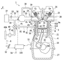
図1には、第1実施形態に係る可変圧縮比多気筒内燃機関の概略構成を示す。内燃機関(エンジン)1は、シリンダ2が形成されたシリンダブロック3を、クランクシャフト20(図3参照)が組み付けられるクランクケース4に対して、シリンダ軸方向に相対移動させることによって圧縮比を変更するものである。クランクケース4およびシリンダブロック3は、圧縮比可変機構21により、上下方向ないしシリンダ軸方向に近接離反移動可能に連結される。なお本実施形態の内燃機関1はガソリンエンジン(火花点火式内燃機関)であるが、本発明はディーゼルエンジン(圧縮着火式内燃機関)にも適用可能である。
Hereinafter, preferred embodiments of the present invention will be described with reference to the drawings.
[First Embodiment]
FIG. 1 shows a schematic configuration of a variable compression ratio multi-cylinder internal combustion engine according to the first embodiment. The internal combustion engine (engine) 1 changes the compression ratio by moving the cylinder block 3 formed with the cylinder 2 relative to the crankcase 4 to which the crankshaft 20 (see FIG. 3) is assembled in the cylinder axial direction. To do. The crankcase 4 and the cylinder block 3 are connected by a variable compression ratio mechanism 21 so as to be able to move close to and away from each other in the vertical direction or the cylinder axis direction. The internal combustion engine 1 of the present embodiment is a gasoline engine (spark ignition internal combustion engine), but the present invention is also applicable to a diesel engine (compression ignition internal combustion engine).

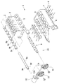
ここで圧縮比可変機構21の構成について説明する。図示されるように、シリンダブロック3の両側下部に複数の隆起部が形成され、この各隆起部に軸受収納孔5が形成されている。軸受収納孔5は、円形であり、シリンダ2の軸方向に対して直角に、かつ複数のシリンダ2の配列方向に平行になるようにそれぞれ形成されている。シリンダブロック3の片側の軸受収納孔5はすべて同軸上に位置している。またシリンダブロック3の両側の軸受収納孔5の一対の中心軸は互いに平行である。   Here, the configuration of the variable compression ratio mechanism 21 will be described. As shown in the drawing, a plurality of raised portions are formed at the lower portions on both sides of the cylinder block 3, and bearing housing holes 5 are formed in the raised portions. The bearing housing holes 5 are circular and formed so as to be perpendicular to the axial direction of the cylinders 2 and parallel to the arrangement direction of the plurality of cylinders 2. The bearing housing holes 5 on one side of the cylinder block 3 are all located on the same axis. A pair of central axes of the bearing housing holes 5 on both sides of the cylinder block 3 are parallel to each other.

クランクケース4には、上述した軸受収納孔5が形成された複数の隆起部の間に位置するように、複数の立壁部が形成されている。各立壁部のクランクケース4外側に向けられた表面には、半円形の凹部が形成されている。また各立壁部には、ボルト6によって取り付けられるキャップ7が用意されており、キャップ7も半円形の凹部を有している。各立壁部にキャップ7を取り付けると、円形のカム収納孔8が形成される。カム収納孔8の形状は、上述した軸受収納孔5と同一である。   A plurality of standing wall portions are formed in the crankcase 4 so as to be positioned between the plurality of raised portions in which the bearing housing holes 5 described above are formed. A semicircular recess is formed on the surface of each standing wall portion facing the outside of the crankcase 4. Moreover, the cap 7 attached with the volt | bolt 6 is prepared for each standing wall part, and the cap 7 also has a semicircle recessed part. When the cap 7 is attached to each standing wall portion, a circular cam housing hole 8 is formed. The shape of the cam storage hole 8 is the same as that of the bearing storage hole 5 described above.

複数のカム収納孔8は、軸受収納孔5と同様、シリンダブロック3をクランクケース4に取り付けたときにシリンダ2の軸方向に対して直角に、且つ、複数のシリンダ2の配列方向に平行になるようにそれぞれ形成されている。これら複数のカム収納孔8も、シリンダブロック3の両側に配置されることとなり、片側の複数のカム収納孔8はすべて同軸上に位置している。シリンダブロック3の両側に配置されたカム収納孔8の一対の中心軸は互いに平行である。また、両側における各軸受収納孔5の間の距離と、両側における各カム収納孔8との間の距離は同一である。   The plurality of cam storage holes 8, like the bearing storage holes 5, are perpendicular to the axial direction of the cylinders 2 when the cylinder block 3 is attached to the crankcase 4 and parallel to the arrangement direction of the plurality of cylinders 2. Each is formed to be. The plurality of cam storage holes 8 are also arranged on both sides of the cylinder block 3, and the plurality of cam storage holes 8 on one side are all located coaxially. A pair of central axes of the cam housing holes 8 arranged on both sides of the cylinder block 3 are parallel to each other. Further, the distance between the bearing housing holes 5 on both sides and the distance between the cam housing holes 8 on both sides are the same.

交互に配置される両側二列の軸受収納孔5とカム収納孔8には、それぞれカム軸9が挿通される。これによりシリンダブロック3とクランクケース4は互いに連結される。カム軸9は、軸部9aと、軸部9aの中心軸に対して偏心された状態で軸部9aに固定され、正円形のカムプロフィールを有するカム部9bと、カム部9bと同一外形を有し軸部9aに対して回転可能に取り付けられる可動軸受部9cとを有する。カム部9bと可動軸受部9cとは交互に配置される。一対のカム軸9は鏡像の関係を有している。また、カム軸9の端部には、ギア10を取り付けるための取り付け部9dが形成されている。軸部9aの中心と取り付け部9dの中心とは偏心しており、カム部9bの中心と取り付け部9dの中心とは互いに一致している。   Cam shafts 9 are respectively inserted into the bearing storage holes 5 and the cam storage holes 8 in two rows on both sides. Thereby, the cylinder block 3 and the crankcase 4 are connected to each other. The cam shaft 9 is fixed to the shaft portion 9a in a state of being eccentric with respect to the shaft portion 9a and the central axis of the shaft portion 9a, and has the same outer shape as the cam portion 9b having a regular circular cam profile. And a movable bearing portion 9c that is rotatably attached to the shaft portion 9a. The cam portions 9b and the movable bearing portions 9c are alternately arranged. The pair of cam shafts 9 have a mirror image relationship. Further, an attachment portion 9 d for attaching the gear 10 is formed at the end portion of the cam shaft 9. The center of the shaft portion 9a and the center of the attachment portion 9d are eccentric, and the center of the cam portion 9b and the center of the attachment portion 9d coincide with each other.

可動軸受部9cも、軸部9aに対して偏心されており、その偏心量はカム部9bと同一である。また、各カム軸9において、複数のカム部9bの偏心方向は同一である。また、可動軸受部9cの外形は、カム部9bと同一直径の正円である。可動軸受部9cを軸部9aに対し回転させることで、カム部9bの外周面と可動軸受部9cの外周面とを互いに一致させることができる。   The movable bearing portion 9c is also eccentric with respect to the shaft portion 9a, and the amount of eccentricity is the same as that of the cam portion 9b. In each camshaft 9, the eccentric directions of the plurality of cam portions 9b are the same. The outer shape of the movable bearing portion 9c is a perfect circle having the same diameter as the cam portion 9b. By rotating the movable bearing portion 9c with respect to the shaft portion 9a, the outer peripheral surface of the cam portion 9b and the outer peripheral surface of the movable bearing portion 9c can be made to coincide with each other.

各カム軸9の取り付け部9dにはギア10が取り付けられる。一対のカム軸9の端部に固定された一対のギア10には、それぞれウォームギア11a、11bが噛合される。ウォームギア11a、11bは単一のモータ12の一本の出力軸に取り付けられている。ウォームギア11a、11bは、互いに逆方向に回転する螺旋溝を有している。このため、モータ12を一方向に回転させると、一対のカム軸9、9は、ウォームギア11a、11bおよびギア10、10を介して互いに逆方向に回転する。モータ12はシリンダブロック3に固定されている。   A gear 10 is attached to the attachment portion 9d of each camshaft 9. Worm gears 11a and 11b are meshed with the pair of gears 10 fixed to the ends of the pair of cam shafts 9, respectively. The worm gears 11 a and 11 b are attached to one output shaft of the single motor 12. The worm gears 11a and 11b have spiral grooves that rotate in opposite directions. For this reason, when the motor 12 is rotated in one direction, the pair of cam shafts 9 and 9 rotate in the opposite directions via the worm gears 11 a and 11 b and the gears 10 and 10. The motor 12 is fixed to the cylinder block 3.

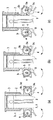
次に、圧縮比可変機構21の作動を説明する。図2(a)〜(c)に、シリンダブロック3と、クランクケース4と、これらの間に配設されたカム軸9との関係を示した断面図を示す。軸部9aの中心軸をa、カム部9bの中心をb、可動軸受部9cの中心をcとして示す。図2(a)は、軸部9aの延長線上から見て全てのカム部9b及び可動軸受部9cの外周面が一致した状態を示す。このとき、一対の軸部9aは、軸受収納孔5及びカム収納孔8の中で外側に位置している。   Next, the operation of the compression ratio variable mechanism 21 will be described. 2A to 2C are cross-sectional views showing the relationship between the cylinder block 3, the crankcase 4, and the camshaft 9 disposed therebetween. The center axis of the shaft portion 9a is indicated by a, the center of the cam portion 9b is indicated by b, and the center of the movable bearing portion 9c is indicated by c. FIG. 2A shows a state in which the outer peripheral surfaces of all the cam portions 9b and the movable bearing portion 9c coincide with each other when viewed from the extension line of the shaft portion 9a. At this time, the pair of shaft portions 9 a are located outside the bearing housing hole 5 and the cam housing hole 8.

図2(a)の状態から、モータ12を駆動して軸部9aを矢印方向に回転させると、図2(b)の状態になる。このとき、軸部9aに対して、カム部9bと可動軸受部9cの偏心方向にずれが生じるので、クランクケース4に対してシリンダブロック3を相対的に上方ないし上死点側にスライドさせ、離反方向に移動させることができる。そしてそのスライド量は、図2(c)のような状態となるまでカム軸9を回転させたときが最大となり、カム部9bや可動軸受部9cの偏心量の2倍となる。カム部9b及び可動軸受部9cは、それぞれカム収納孔8及び軸受収納孔5の内部で回転し、それぞれカム収納孔8及び軸受収納孔5の内部で軸部9aの位置が移動するのを許容している。   When the motor 12 is driven from the state of FIG. 2A to rotate the shaft portion 9a in the direction of the arrow, the state of FIG. At this time, since the cam portion 9b and the movable bearing portion 9c are displaced in the eccentric direction with respect to the shaft portion 9a, the cylinder block 3 is slid relative to the crankcase 4 to the upper or top dead center side, It can be moved in the direction of separation. The sliding amount is maximized when the cam shaft 9 is rotated until the state shown in FIG. 2C is reached, and is twice the eccentric amount of the cam portion 9b and the movable bearing portion 9c. The cam portion 9b and the movable bearing portion 9c rotate inside the cam storage hole 8 and the bearing storage hole 5, respectively, and allow the position of the shaft portion 9a to move inside the cam storage hole 8 and the bearing storage hole 5, respectively. doing.

図示しないが、図2(c)の状態からモータ12を駆動して軸部9aを矢印方向と逆の方向に回転させると、図2(b)または図2(a)の状態へと、クランクケース4に対してシリンダブロック3を相対的に下方ないし下死点側にスライドさせ、近接方向に移動させることができる。   Although not shown, when the motor 12 is driven from the state of FIG. 2 (c) to rotate the shaft portion 9a in the direction opposite to the arrow direction, the crank is moved to the state of FIG. 2 (b) or FIG. 2 (a). The cylinder block 3 can be slid relative to the case 4 downward or at the bottom dead center, and moved in the proximity direction.

この機構を用いることによって、シリンダブロック3をクランクケース4に対してシリンダ軸方向に相対移動させることが可能となり、圧縮比を変更することができる。   By using this mechanism, the cylinder block 3 can be moved relative to the crankcase 4 in the cylinder axial direction, and the compression ratio can be changed.

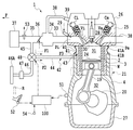
次に、図3を用いて、車両(図示せず)に搭載された上述の内燃機関1を説明する。図3において、矢印Fで示す方向が車両の前方である。図示しないが、本実施形態においては、内燃機関1のクランクケース4がエンジンマウントを介して車両に固定されている。よって固定されたクランクケース4に対しシリンダブロック3が昇降することとなる。但しマウント方法を逆にし、シリンダブロック3を車両に固定してもよい。図示例はフロントエンジン車の例であり、内燃機関1は車両前側のエンジンルーム内に格納されている。   Next, the above-described internal combustion engine 1 mounted on a vehicle (not shown) will be described with reference to FIG. In FIG. 3, the direction indicated by the arrow F is the front of the vehicle. Although not shown, in the present embodiment, the crankcase 4 of the internal combustion engine 1 is fixed to the vehicle via an engine mount. Therefore, the cylinder block 3 moves up and down with respect to the fixed crankcase 4. However, the mounting method may be reversed to fix the cylinder block 3 to the vehicle. The illustrated example is an example of a front engine vehicle, and the internal combustion engine 1 is stored in an engine room on the front side of the vehicle.

内燃機関1は、シリンダ2内に昇降可能に配置されたピストン24と、シリンダブロック2の上部に取り付けられたシリンダヘッド25と、シリンダヘッド25の上部に取り付けられてこれを上方から覆うヘッドカバー26と、クランクケース4の底部に取り付けられてこれを下方から覆うオイルパン27とを備える。ピストン24はコンロッド19を介してクランクシャフト20に連結される。   The internal combustion engine 1 includes a piston 24 that can be moved up and down in the cylinder 2, a cylinder head 25 that is attached to the top of the cylinder block 2, and a head cover 26 that is attached to the top of the cylinder head 25 and covers it from above. The oil pan 27 is attached to the bottom of the crankcase 4 and covers it from below. The piston 24 is connected to the crankshaft 20 via a connecting rod 19.

ヘッドカバー26およびシリンダヘッド25の内部には動弁室28が画成される。動弁室28には、吸気ポートPi及び排気ポートPeをそれぞれ開閉する吸気弁Vi及び排気弁Veと、吸気弁Vi及び排気弁Veをそれぞれ閉弁方向に付勢するバルブスプリング(図示せず)と、吸気弁Vi及び排気弁Veをそれぞれ開弁方向に駆動する吸気カムシャフトCi及び排気カムシャフトCeとが設けられる。動弁室28には図示しないオイル供給口から動弁系潤滑のためのオイルが供給されている。シリンダヘッド25には燃料を噴射するためのインジェクタ29と、混合気を点火するための点火プラグ30とが取り付けられている。   A valve operating chamber 28 is defined inside the head cover 26 and the cylinder head 25. In the valve operating chamber 28, an intake valve Vi and an exhaust valve Ve that open and close the intake port Pi and the exhaust port Pe, respectively, and a valve spring (not shown) that urges the intake valve Vi and the exhaust valve Ve in a valve closing direction, respectively. And an intake camshaft Ci and an exhaust camshaft Ce that drive the intake valve Vi and the exhaust valve Ve in the valve opening direction, respectively. The valve operating chamber 28 is supplied with oil for valve operating lubrication from an oil supply port (not shown). An injector 29 for injecting fuel and a spark plug 30 for igniting the air-fuel mixture are attached to the cylinder head 25.

ピストン24の上方には燃焼室31が画成され、ピストン24の下方にはクランク室32が画成される。クランク室32にはクランクシャフト20が設けられると共に、その底部にはオイル(図示せず)が貯留される。   A combustion chamber 31 is defined above the piston 24, and a crank chamber 32 is defined below the piston 24. A crankshaft 20 is provided in the crank chamber 32, and oil (not shown) is stored at the bottom thereof.

吸気ポートPiには気筒毎の吸気マニホールド33を介してサージタンク34が接続され、サージタンク34から各気筒の吸気ポートPiに吸気マニホールド33を介して吸気を分配するようになっている。サージタンク34の上流側には吸気管35が接続され、吸気管35には電子制御式スロットルバルブ36とエアフィルタ37が設けられている。これら吸気ポートPi、吸気マニホールド33、サージタンク34および吸気管35により吸気通路が画成される。   A surge tank 34 is connected to the intake port Pi via an intake manifold 33 for each cylinder, and intake air is distributed from the surge tank 34 to the intake port Pi of each cylinder via the intake manifold 33. An intake pipe 35 is connected to the upstream side of the surge tank 34, and an electronically controlled throttle valve 36 and an air filter 37 are provided in the intake pipe 35. An intake passage is defined by the intake port Pi, the intake manifold 33, the surge tank 34, and the intake pipe 35.

各気筒の排気ポートPeには排気マニホールド38を介して排気管(図示せず)が接続され、これら排気ポートPe、排気マニホールド38および排気管により排気通路が画成される。   An exhaust pipe (not shown) is connected to the exhaust port Pe of each cylinder via an exhaust manifold 38, and an exhaust passage is defined by the exhaust port Pe, the exhaust manifold 38 and the exhaust pipe.

内燃機関1には、燃焼室31からピストン24とシリンダ2の隙間を通過してクランク室32に漏れ出たブローバイガスを処理するための装置が装備されている。すなわち、クランク室32内に漏れ出たブローバイガスは、シリンダブロック2およびクランクケース4に設けられたオイル落とし穴(図示せず)等を上昇して動弁室28に至る。そしてこのブローバイガスを吸気通路に環流させるため、動弁室28がサージタンク34にブローバイガス通路38を介して連通接続されている。ブローバイガス通路38の入口部には、吸気負圧ないし負荷に応じて開度が調節されるPCV(Positive Crankcase Ventilation)バルブ39が設けられ、このPCVバルブ39はヘッドカバー26に取り付けられている。   The internal combustion engine 1 is equipped with a device for processing blow-by gas leaked from the combustion chamber 31 through the gap between the piston 24 and the cylinder 2 and leaking into the crank chamber 32. That is, the blow-by gas leaking into the crank chamber 32 rises through an oil drop hole (not shown) provided in the cylinder block 2 and the crankcase 4 and reaches the valve operating chamber 28. In order to circulate this blow-by gas through the intake passage, the valve operating chamber 28 is connected to the surge tank 34 via the blow-by gas passage 38. A PCV (Positive Crankcase Ventilation) valve 39 whose opening degree is adjusted according to the intake negative pressure or load is provided at the inlet of the blowby gas passage 38, and the PCV valve 39 is attached to the head cover 26.

他方、内燃機関1の内部に、換気用の新気ないし外気を導入するための装置も装備されている。これについては後に詳述する。   On the other hand, the internal combustion engine 1 is also equipped with a device for introducing fresh air or external air for ventilation. This will be described in detail later.

図示されるように、シリンダブロック3の下部側は、クランクケース4の上部側の内側にシリンダ軸方向に移動可能に嵌め入れられている。特に、当該嵌合部分において、シリンダブロック3の下部側が上部側に対し側方かつ外側に突出され、その突出部分においてシリンダブロック3がクランクケース4に対し摺動可能となっている。当該嵌合部分において、シリンダブロック3はクランクケース4により外側から覆われ、この部分で特にシリンダブロック3の放熱性および冷却性が低下している。この放熱性および冷却性の低下を抑制するのが本発明の目的の一つである。シリンダブロック3の内部にはシリンダ2を取り囲むようウォータジャケットWが画成されている。   As shown in the drawing, the lower side of the cylinder block 3 is fitted inside the upper side of the crankcase 4 so as to be movable in the cylinder axial direction. In particular, in the fitting portion, the lower side of the cylinder block 3 protrudes laterally and outward with respect to the upper side, and the cylinder block 3 can slide with respect to the crankcase 4 at the protruding portion. In the fitting portion, the cylinder block 3 is covered from the outside by the crankcase 4, and in particular, the heat dissipation and cooling properties of the cylinder block 3 are lowered at this portion. It is one of the objects of the present invention to suppress this decrease in heat dissipation and cooling properties. A water jacket W is defined in the cylinder block 3 so as to surround the cylinder 2.

シリンダブロック2とクランクケース4の嵌合部ないし摺動部をシールするため、シール部材40が設けられている。シール部材40は、その全体がシリンダブロック2の外周側面の周りを1周するような環状に形成されると共に、その断面が図示の如き蛇腹状に形成された弾性体からなる。シール部材40の上端縁部はシリンダブロック2とシリンダヘッド25との間に挟まれて固定され、シール部材40の下端縁部はクランクケース4に固定されている。   A seal member 40 is provided to seal a fitting portion or a sliding portion between the cylinder block 2 and the crankcase 4. The seal member 40 is formed in an annular shape so that the whole of the seal member 40 makes one round around the outer peripheral side surface of the cylinder block 2 and is made of an elastic body whose cross section is formed in a bellows shape as shown in the drawing. The upper end edge of the seal member 40 is sandwiched and fixed between the cylinder block 2 and the cylinder head 25, and the lower end edge of the seal member 40 is fixed to the crankcase 4.

シリンダブロック3が下降してクランクケース4に近づいたとき(圧縮比が高くなったとき)、シール部材40は収縮する。シリンダブロック2が上昇してクランクケース4から遠ざかったとき(圧縮比が低くなったとき)、シール部材40は伸長する。こうして、シリンダブロック2とクランクケース3との相対位置が変化してもシール部材40の伸縮により嵌合部ないし摺動部の気密性を保つことができる。   When the cylinder block 3 descends and approaches the crankcase 4 (when the compression ratio becomes high), the seal member 40 contracts. When the cylinder block 2 rises and moves away from the crankcase 4 (when the compression ratio becomes low), the seal member 40 extends. Thus, even if the relative position between the cylinder block 2 and the crankcase 3 changes, the sealing member 40 can be expanded and contracted to maintain the airtightness of the fitting portion or the sliding portion.

図示するように、シリンダブロック3、クランクケース4およびシール部材40により囲まれた空間41が形成される。この空間41は、シリンダブロック3およびシール部材40により挟まれた上部側空間41Aと、シリンダブロック3およびクランクケース4により挟まれた下部側空間41Bとからなる。   As illustrated, a space 41 surrounded by the cylinder block 3, the crankcase 4, and the seal member 40 is formed. The space 41 includes an upper space 41A sandwiched between the cylinder block 3 and the seal member 40 and a lower space 41B sandwiched between the cylinder block 3 and the crankcase 4.

シール部材40によってもシリンダブロック3が外側から覆われるので、シリンダブロック3の放熱性および冷却性が低下している。そこで放熱性および冷却性を高めるため、本実施形態では次の構成を採用する。   Since the cylinder block 3 is also covered from the outside by the seal member 40, the heat dissipation and cooling performance of the cylinder block 3 are deteriorated. Therefore, in order to improve heat dissipation and cooling performance, the present embodiment employs the following configuration.

すなわち、内燃機関1の内部に新気を排出するための新気排出路42が、シリンダブロック3に指向させて設けられている。本実施形態において新気排出路42は、下部側空間41Bを画成するクランクケース4の部分に貫通形成された排出口43と、排出口43に連通接続され外部に延びる排出通路44とを含む。すなわち新気排出路42は下部側空間41Bに連通される。新気排出路42ないし排出口43の出口は、同じく下部側空間41Bを画成するシリンダブロック3の部分に向けられ、矢印F3で示すように、排出口43から排出された新気を当該部分に当てるようになっている。   That is, a fresh air discharge passage 42 for discharging fresh air into the internal combustion engine 1 is provided so as to face the cylinder block 3. In the present embodiment, the fresh air discharge passage 42 includes a discharge port 43 formed through the portion of the crankcase 4 that defines the lower side space 41B, and a discharge passage 44 that is connected to the discharge port 43 and extends to the outside. . That is, the fresh air discharge path 42 communicates with the lower space 41B. The outlet of the fresh air discharge passage 42 or the discharge port 43 is directed to the portion of the cylinder block 3 that similarly defines the lower space 41B, and the fresh air discharged from the discharge port 43 as shown by the arrow F3 It is supposed to be applied to.

排出口43は、貫通穴から形成してもよいし、クランクケース4に埋め込んだパイプから形成してもよい。新気排出路42の出口をシリンダブロック3の摺動部に向け、当該摺動部に新気を当てるようにしてもよい。新気を当てる位置は任意である。シール部材40を貫通して新気排出路42を設けてもよい。   The discharge port 43 may be formed from a through hole or a pipe embedded in the crankcase 4. The outlet of the fresh air discharge path 42 may be directed toward the sliding portion of the cylinder block 3 so that fresh air is applied to the sliding portion. The position to apply freshness is arbitrary. A fresh air discharge passage 42 may be provided through the seal member 40.

新気排出路42から排出された新気は、シリンダブロック3およびクランクケース4の間の図示しない隙間、もしくはシリンダブロック3およびクランクケース4の少なくとも一方に形成された新気通路を通って、クランク室32に送られる。これにより新気が内燃機関1の内部あるいはクランク室32に送られ、換気が実現される。   Fresh air discharged from the fresh air discharge passage 42 passes through a gap (not shown) between the cylinder block 3 and the crankcase 4 or a fresh air passage formed in at least one of the cylinder block 3 and the crankcase 4 to Sent to chamber 32. Thus, fresh air is sent to the inside of the internal combustion engine 1 or to the crank chamber 32, and ventilation is realized.

一方、吸気通路から新気を抽出するための新気抽出路45が設けられる。新気抽出路45の入口ないし上流端はスロットルバルブ36より上流側の吸気管35に接続されており、この位置において新気抽出路45は吸気通路から新気を抽出する。   On the other hand, a fresh air extraction passage 45 for extracting fresh air from the intake passage is provided. The inlet or upstream end of the fresh air extraction path 45 is connected to the intake pipe 35 upstream of the throttle valve 36, and the fresh air extraction path 45 extracts fresh air from the intake passage at this position.

さらに、吸気通路以外の箇所から新気を導入する新気導入路46が設けられる。新気導入路46の上流端はエンジンルーム内で開放された自由端となっている。   Furthermore, a fresh air introduction path 46 for introducing fresh air from a place other than the intake passage is provided. The upstream end of the fresh air introduction path 46 is a free end opened in the engine room.

特に、好ましい態様として、新気導入路46の入口46Aは、車両走行時の走行風に対向するよう位置され且つ指向されている。具体的には、当該入口46Aは、車両前方Fに向かって指向され、車両に対し後ろ向きに流れてくる走行風に向かい合い、走行風を直接的に且つ効率良く回収するようになっている。   In particular, as a preferred embodiment, the inlet 46A of the fresh air introduction path 46 is positioned and oriented so as to face the traveling wind during vehicle traveling. Specifically, the inlet 46A is directed toward the front F of the vehicle, faces the traveling wind flowing backward with respect to the vehicle, and collects the traveling wind directly and efficiently.

また当該入口46Aは、車両前端部に位置され、特に車両前端部に配置されたラジエータRに対し、車両前方側から見てオフセットして位置されている。当該入口46Aは、好ましくはラジエータRよりも上方、より好ましくはラジエータRよりも上方かつ前方に位置されている。これにより、ラジエータから後方に排出された熱気が入口46Aに導入されることがなくなり、十分に低温の新気のみを導入できる。   The inlet 46A is located at the front end of the vehicle, and is offset from the radiator R disposed at the front end of the vehicle, as viewed from the front side of the vehicle. The inlet 46A is preferably located above the radiator R, more preferably above and ahead of the radiator R. As a result, hot air discharged rearward from the radiator is not introduced into the inlet 46A, and only sufficiently low temperature fresh air can be introduced.

図示例において、入口46Aは、走行風を効率的に回収するよう拡径されている。また新気導入路46の途中には、導入した新気ないし走行風を濾過するための新気フィルタ47が設けられる。   In the illustrated example, the inlet 46A is enlarged in diameter so as to efficiently collect the traveling wind. Further, a fresh air filter 47 for filtering the introduced fresh air or running wind is provided in the middle of the fresh air introduction path 46.

また、新気排出路42と新気抽出路45の連通状態、および新気排出路42と新気導入路46の連通状態を調節する弁手段が設けられる。当該弁手段は、具体的には図示されるような単一の切替弁48からなる。切替弁48には、排出通路44の上流端と、新気抽出路45の下流端と、新気導入路46の下流端とが接続される。切替弁48は電磁三方弁からなり、新気抽出路45と新気導入路46の一方を新気排出路42に択一的に接続する。もっとも、このような択一的な切替だけでなく、中間的な切替動作を行って、新気抽出路45および新気導入路46から新気排出路42にそれぞれ送られる新気量の割合を変更するようにしてもよい。   Further, valve means for adjusting the communication state of the fresh air discharge path 42 and the fresh air extraction path 45 and the communication state of the fresh air discharge path 42 and the fresh air introduction path 46 are provided. Specifically, the valve means comprises a single switching valve 48 as shown. The switching valve 48 is connected to the upstream end of the discharge passage 44, the downstream end of the fresh air extraction passage 45, and the downstream end of the fresh air introduction passage 46. The switching valve 48 is an electromagnetic three-way valve, and selectively connects one of the fresh air extraction path 45 and the fresh air introduction path 46 to the fresh air discharge path 42. However, not only such alternative switching but also intermediate switching operation is performed, and the ratio of the amount of fresh air sent from the fresh air extraction path 45 and the fresh air introduction path 46 to the fresh air discharge path 42 is determined. It may be changed.

本実施形態では新気抽出路45と新気導入路46の切り替えを単一の切替弁48で行うが、これに限らず、弁手段は複数の弁で構成してもよい。例えば新気抽出路45と新気導入路46に個別に弁を設けてもよい。また通路構成も様々な変形が可能である。   In the present embodiment, the fresh air extraction path 45 and the fresh air introduction path 46 are switched by a single switching valve 48, but the present invention is not limited to this, and the valve means may be configured by a plurality of valves. For example, valves may be provided individually for the fresh air extraction path 45 and the fresh air introduction path 46. Also, the passage configuration can be variously modified.

内燃機関1には、インジェクタ29、点火プラグ30、スロットルバルブ36、圧縮比可変機構21のモータ12、切替弁48などの各種機器を電気的に制御するため、制御手段としての電子制御ユニット(ECU)100が併設されている。ECU100は、CPU、ROM、RAM、バックアップRAMなどから構成されるユニットである。   The internal combustion engine 1 includes an electronic control unit (ECU) as a control means for electrically controlling various devices such as the injector 29, the spark plug 30, the throttle valve 36, the motor 12 of the variable compression ratio mechanism 21, and the switching valve 48. ) 100 is attached. The ECU 100 is a unit that includes a CPU, a ROM, a RAM, a backup RAM, and the like.

ECU100には、クランクポジションセンサ51、アクセルポジションセンサ52、エアフローメータ53、水温センサ54などの各種センサの電気信号が入力される。クランクポジションセンサ51はクランクシャフト20の回転位置に相関したパルス信号を出力する。アクセルポジションセンサ52は、アクセルペダルの操作量(アクセル開度)に相関した信号を出力する。エアフローメータ53は、単位時間当たりの吸入空気量に相関した信号を出力する。水温センサ54は、内燃機関1の冷却水の温度に相関した信号を出力する。   The ECU 100 receives electrical signals from various sensors such as a crank position sensor 51, an accelerator position sensor 52, an air flow meter 53, and a water temperature sensor 54. The crank position sensor 51 outputs a pulse signal correlated with the rotational position of the crankshaft 20. The accelerator position sensor 52 outputs a signal correlated with the operation amount (accelerator opening) of the accelerator pedal. The air flow meter 53 outputs a signal correlated with the intake air amount per unit time. The water temperature sensor 54 outputs a signal correlated with the temperature of the cooling water of the internal combustion engine 1.

ECU100は、上記した各種センサの電気信号に従って内燃機関1の運転状態(機関運転状態)を検出し、その検出結果に従って上記した各種機器を制御する。たとえば、ECU100は、クランクポジションセンサ51の出力信号から検出される内燃機関の回転数(機関回転数)と、アクセルポジションセンサ52の出力信号から検出される内燃機関の負荷(機関負荷)とに基づいて、圧縮比可変機構21を制御する。   The ECU 100 detects the operating state (engine operating state) of the internal combustion engine 1 according to the electrical signals of the various sensors described above, and controls the various devices described above according to the detection results. For example, ECU 100 is based on the rotational speed of the internal combustion engine (engine rotational speed) detected from the output signal of crank position sensor 51 and the load of the internal combustion engine (engine load) detected from the output signal of accelerator position sensor 52. Thus, the compression ratio variable mechanism 21 is controlled.

その際、機関回転数および機関負荷が予め定められた低回転・低負荷運転領域にあるときには、ECU100は、内燃機関1の圧縮比が高くなるよう、言い換えればシリンダブロック3がクランクケース4に近づくよう、圧縮比可変機構21を制御する。   At this time, when the engine speed and the engine load are in a predetermined low rotation / low load operation region, the ECU 100 causes the compression ratio of the internal combustion engine 1 to increase, in other words, the cylinder block 3 approaches the crankcase 4. Thus, the variable compression ratio mechanism 21 is controlled.

また、機関回転数および機関負荷が上記低回転・低負荷運転領域から外れたときには、ECU100は、内燃機関1の圧縮比が低くなるよう、言い換えればシリンダブロック3がクランクケース4から遠ざかるよう、圧縮比可変機構21を制御する。   Further, when the engine speed and the engine load deviate from the low rotation / low load operation region, the ECU 100 compresses the internal combustion engine 1 so that the compression ratio is lowered, in other words, the cylinder block 3 is moved away from the crankcase 4. The ratio variable mechanism 21 is controlled.

圧縮比は、上述の如く2段階に切り換えられてもよいが、機関回転数および機関負荷に応じて無段階に切り換えられてもよい。   The compression ratio may be switched in two steps as described above, but may be switched in a stepless manner according to the engine speed and the engine load.

このように内燃機関1の圧縮比が変更されると、低回転・低負荷運転領域における燃焼効率の向上と、当該領域外の高回転または高負荷運転領域におけるノッキングの抑制とを両立することができる。   Thus, when the compression ratio of the internal combustion engine 1 is changed, it is possible to achieve both improvement in combustion efficiency in the low rotation / low load operation region and suppression of knocking in the high rotation or high load operation region outside the region. it can.

ところで、ECU100は、検出された機関負荷に応じて切替弁48を制御する。具体的にはECU100は、検出された機関負荷が低負荷相当の所定値未満であるときには、新気抽出路45のみを新気排出路42に接続し、新気導入路46が新気排出路42に対し未接続となるよう、切替弁48を第1の位置に切り替える。すなわち、新気排出路42と新気抽出路45の連通状態が全開状態となり且つ新気排出路42と新気導入路46の連通状態が全閉状態となるよう、切替弁48を制御する。なお、ここでいう機関負荷の所定値は、高圧縮比と低圧縮比とを切り替える前記低回転・低負荷運転領域の境界を規定する負荷に等しくしてもよいし、異ならせてもよい。等しくした場合、高圧縮比および低圧縮比の切り替えと、通路の切り替えとが同時に起こる。   By the way, the ECU 100 controls the switching valve 48 according to the detected engine load. Specifically, when the detected engine load is less than a predetermined value corresponding to a low load, the ECU 100 connects only the fresh air extraction path 45 to the fresh air discharge path 42 and the fresh air introduction path 46 serves as the fresh air discharge path. The switching valve 48 is switched to the first position so that it is not connected to 42. That is, the switching valve 48 is controlled so that the communication state of the fresh air discharge path 42 and the fresh air extraction path 45 is fully opened and the communication state of the fresh air discharge path 42 and the fresh air introduction path 46 is fully closed. Note that the predetermined value of the engine load here may be equal to or different from the load that defines the boundary of the low rotation / low load operation region where the high compression ratio and the low compression ratio are switched. If they are equal, the switching of the high compression ratio and the low compression ratio and the switching of the passages occur simultaneously.

これにより、吸気通路から新気抽出路45に抽出された新気のみが、図3に矢印F1で示すように、切替弁48、新気排出路42を順に経てシリンダブロック3に当てられる。   As a result, only fresh air extracted from the intake passage to the fresh air extraction passage 45 is applied to the cylinder block 3 through the switching valve 48 and the fresh air discharge passage 42 in this order, as indicated by an arrow F1 in FIG.

他方、ECU100は、検出された機関負荷が高負荷相当の所定値以上であるときには、新気導入路46のみを新気排出路42に接続し、新気抽出路45が新気排出路42に対し未接続となるよう、切替弁48を第2の位置に切り替える。すなわち、新気排出路42と新気抽出路45の連通状態が全閉状態となり且つ新気排出路42と新気導入路46の連通状態が全開状態となるよう、切替弁48を制御する。   On the other hand, when the detected engine load is equal to or higher than a predetermined value corresponding to a high load, the ECU 100 connects only the fresh air introduction path 46 to the fresh air discharge path 42 and the fresh air extraction path 45 to the fresh air discharge path 42. On the other hand, the switching valve 48 is switched to the second position so as not to be connected. That is, the switching valve 48 is controlled so that the communication state of the fresh air discharge path 42 and the fresh air extraction path 45 is fully closed and the communication state of the fresh air discharge path 42 and the fresh air introduction path 46 is fully open.

これにより、新気導入路46に導入された新気のみが、図3に矢印F2で示すように、切替弁48、新気排出路42を順に経てシリンダブロック3に当てられる。   Thereby, only the fresh air introduced into the fresh air introduction path 46 is applied to the cylinder block 3 through the switching valve 48 and the fresh air discharge path 42 in this order, as indicated by an arrow F2 in FIG.

このように本実施形態によれば、換気用の新気をシリンダブロック3に常時当てることができるので、シリンダブロック3の放熱性および冷却性を高めることができる。また新気導入路46により吸気通路以外の箇所から新気を導入し、これをシリンダブロック3に当てられるようにしたため、吸気通路内から抽出した新気に比べ、より低温の新気をシリンダブロック3に当てることができ、放熱性および冷却性をより高めることができる。   Thus, according to this embodiment, since the fresh air for ventilation can be always applied to the cylinder block 3, the heat dissipation and cooling performance of the cylinder block 3 can be improved. In addition, fresh air is introduced from a portion other than the intake passage through the fresh air introduction path 46 so that the fresh air can be applied to the cylinder block 3, so that fresh air having a lower temperature than the fresh air extracted from the intake passage is supplied to the cylinder block. 3 and the heat dissipation and cooling properties can be further enhanced.

また切替弁48により、シリンダブロック3に当てる新気を、新気抽出路45により抽出した相対的に高温な新気と、新気導入路46により導入した相対的に低温な新気との間で切り替えるようにした。そのため、シリンダブロック3の放熱を促進したくないような場合、すなわち上述した低負荷運転時や機関暖機時には、通常の内燃機関同様、新気抽出路45により抽出した相対的に高温な新気をシリンダブロック3に当て、シリンダブロック3の保温性を確保し、暖機性を確保できる。   Further, the switching valve 48 allows the fresh air applied to the cylinder block 3 between the relatively hot fresh air extracted by the fresh air extraction passage 45 and the relatively cool fresh air introduced by the fresh air introduction passage 46. Switched with. Therefore, in the case where it is not desired to promote the heat radiation of the cylinder block 3, that is, during the low load operation or when the engine is warmed up, the relatively high temperature fresh air extracted by the fresh air extraction passage 45 as in a normal internal combustion engine. Can be applied to the cylinder block 3 to ensure the heat retention of the cylinder block 3 and to ensure warm-up.

他方、シリンダブロック3の放熱を促進したいような場合、すなわちシリンダブロック温度が高くなる上述した高負荷運転時には、新気導入路46により導入した相対的に低温の新気をシリンダブロック3に当て、シリンダブロック3の放熱性および冷却性を向上できる。この際、新気導入路46の入口46Aが上述のように位置され指向されていることから、低温の走行風ないしフレッシュエアをスムーズ且つ効率よく導入し、シリンダブロック3に当てることができる。特に高負荷運転時にはクランク室32の内圧が高くなる傾向にあるが、このときにも走行風の勢いないし慣性を利用して、新気を比較的大量に機関内部に導入できる。このため、シリンダブロック3の放熱性および冷却性の向上に非常に有利である。   On the other hand, when it is desired to promote heat dissipation of the cylinder block 3, that is, during the above-described high load operation in which the cylinder block temperature becomes high, the relatively low temperature fresh air introduced by the fresh air introduction passage 46 is applied to the cylinder block 3, The heat dissipation and cooling performance of the cylinder block 3 can be improved. At this time, since the inlet 46A of the fresh air introduction path 46 is positioned and oriented as described above, low-temperature traveling wind or fresh air can be introduced smoothly and efficiently and applied to the cylinder block 3. In particular, the internal pressure of the crank chamber 32 tends to increase during high-load operation. Even at this time, a relatively large amount of fresh air can be introduced into the engine by using the wind force and inertia. For this reason, it is very advantageous for improvement of heat dissipation and cooling performance of the cylinder block 3.

このように、機関運転状態に応じた最適な新気をシリンダブロック3に当て、且つ機関内部に導入することができる。   Thus, the optimum fresh air according to the engine operating state can be applied to the cylinder block 3 and introduced into the engine.

上記においては切替弁48を択一的に切り替え、低負荷時と高負荷時とで新気抽出路45と新気導入路46を択一的に切り替えるようにした。しかしながら、切替弁48を中間開度に制御し、新気抽出路45からの新気と新気導入路46からの新気との混合割合を機関負荷に応じて連続的に可変とすることも可能である。例えば、機関負荷が高くなるほど後者の新気割合を前者の新気割合に対して増加させるような制御も好ましい。   In the above, the switching valve 48 is selectively switched, and the fresh air extraction path 45 and the fresh air introduction path 46 are selectively switched between a low load and a high load. However, it is also possible to control the switching valve 48 to an intermediate opening so that the mixing ratio of the fresh air from the fresh air extraction passage 45 and the fresh air from the fresh air introduction passage 46 is continuously variable according to the engine load. Is possible. For example, it is also preferable to control such that the latter fresh air ratio is increased with respect to the former fresh air ratio as the engine load increases.

新気導入路46の入口46Aは、必ずしも車両前方に向かって指向する必要はない。例えば車両のフロア下からエンジンルーム内に巻き上げて走行風が流入するような場合には、その走行風に対向するよう、新気導入路46の入口46Aを下向きにすることが可能である。いずれにしても新気導入路46の入口46Aは、走行風の流れ方向と入口46Aの軸線方向とが一致するよう、また走行風が直接導入されるよう、走行風に対向させて指向させるのが好ましい。   The inlet 46A of the fresh air introduction path 46 does not necessarily have to be directed toward the front of the vehicle. For example, when the traveling wind flows into the engine room from below the floor of the vehicle, the inlet 46A of the fresh air introduction path 46 can be directed downward so as to face the traveling wind. In any case, the inlet 46A of the fresh air introduction path 46 is directed to face the traveling wind so that the flow direction of the traveling wind coincides with the axial direction of the inlet 46A, and the traveling wind is directly introduced. Is preferred.

また、新気導入路46の入口46Aは、必ずしも車両前端部に位置させる必要はない。例えばリアエンジン車やミッドシップエンジン車の場合、内燃機関1に近い車両の中央部または後端部に新気導入路46の入口46Aを位置させることが可能である。新気導入路46の入口46Aから新気排出路42の出口(排出口43)までの距離ができるだけ近い方が、より低温の新気を機関内部に導入できるからである。   Further, the inlet 46A of the fresh air introduction path 46 does not necessarily need to be positioned at the vehicle front end. For example, in the case of a rear engine vehicle or a midship engine vehicle, the inlet 46A of the fresh air introduction path 46 can be positioned at the center or rear end of the vehicle close to the internal combustion engine 1. This is because the cooler fresh air can be introduced into the engine when the distance from the inlet 46A of the fresh air introduction path 46 to the outlet (exhaust port 43) of the fresh air discharge path 42 is as short as possible.

[第2実施形態]
次に、本発明の第2実施形態を説明する。なお第1実施形態と同様の部分については説明を省略し、以下相違点を中心に述べる。
[Second Embodiment]
Next, a second embodiment of the present invention will be described. The description of the same parts as in the first embodiment will be omitted, and the differences will be mainly described below.

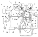
図4に示すように、本実施形態においては、シリンダブロック3の温度を直接的に検出する温度センサ55が設けられている。温度センサ55は、シリンダブロック3の温度に相関した信号をECU100に出力する。なお、水温センサ54によりシリンダブロック3の温度を間接的に検出することも可能である。   As shown in FIG. 4, in the present embodiment, a temperature sensor 55 that directly detects the temperature of the cylinder block 3 is provided. The temperature sensor 55 outputs a signal correlated with the temperature of the cylinder block 3 to the ECU 100. Note that the temperature of the cylinder block 3 can be indirectly detected by the water temperature sensor 54.

本実施形態では、機関負荷の代わりに、温度センサ55により検出されたシリンダブロック温度に応じて切替弁48が制御される。すなわちECU100は、検出されたシリンダブロック温度が相対的に低温な所定値未満であるときには、新気抽出路45のみを新気排出路42に接続し、新気導入路46が新気排出路42に対し未接続となるよう、切替弁48を第1の位置に切り替える。すなわち、新気排出路42と新気抽出路45の連通状態が全開状態となり且つ新気排出路42と新気導入路46の連通状態が全閉状態となるよう、切替弁48を制御する。   In the present embodiment, the switching valve 48 is controlled according to the cylinder block temperature detected by the temperature sensor 55 instead of the engine load. That is, when the detected cylinder block temperature is less than the relatively low predetermined value, the ECU 100 connects only the fresh air extraction path 45 to the fresh air discharge path 42 and the fresh air introduction path 46 serves as the fresh air discharge path 42. The switching valve 48 is switched to the first position so as to be disconnected. That is, the switching valve 48 is controlled so that the communication state of the fresh air discharge path 42 and the fresh air extraction path 45 is fully opened and the communication state of the fresh air discharge path 42 and the fresh air introduction path 46 is fully closed.

これにより、吸気通路から新気抽出路45に抽出された新気のみが、図4に矢印F1で示すように、切替弁48、新気排出路42を順に経てシリンダブロック3に当てられる。   Thereby, only the fresh air extracted from the intake passage to the fresh air extraction passage 45 is applied to the cylinder block 3 through the switching valve 48 and the fresh air discharge passage 42 in this order, as indicated by an arrow F1 in FIG.

他方、ECU100は、検出されたシリンダブロック温度が相対的に高温な所定値以上であるときには、新気導入路46のみを新気排出路42に接続し、新気抽出路45が新気排出路42に対し未接続となるよう、切替弁48を第2の位置に切り替える。すなわち、新気排出路42と新気抽出路45の連通状態が全閉状態となり且つ新気排出路42と新気導入路46の連通状態が全開状態となるよう、切替弁48を制御する。   On the other hand, when the detected cylinder block temperature is equal to or higher than a relatively high predetermined value, the ECU 100 connects only the fresh air introduction path 46 to the fresh air discharge path 42 and the fresh air extraction path 45 serves as the fresh air discharge path. The switching valve 48 is switched to the second position so that it is not connected to 42. That is, the switching valve 48 is controlled so that the communication state of the fresh air discharge path 42 and the fresh air extraction path 45 is fully closed and the communication state of the fresh air discharge path 42 and the fresh air introduction path 46 is fully open.

これにより、新気導入路46に導入された新気のみが、図4に矢印F2で示すように、切替弁48、新気排出路42を順に経てシリンダブロック3に当てられる。   Thereby, only the fresh air introduced into the fresh air introduction path 46 is applied to the cylinder block 3 through the switching valve 48 and the fresh air discharge path 42 in this order, as indicated by an arrow F2 in FIG.

本実施形態によれば、低負荷運転時でありながらシリンダブロック温度が高温となっているような場合、例えば登坂走行後の定常走行時などにおいて、新気導入路46からの低温な新気をシリンダブロック3に当てることができ、シリンダブロック3の放熱性および冷却性を向上することができる。そしてシリンダブロック温度を即座に下げることができる。なお第1実施形態だと、かかる場合には新気抽出路45が新気排出路42に接続され、第1実施形態に比べ相対的に不利である。   According to the present embodiment, when the cylinder block temperature is high during low load operation, for example, during steady running after uphill running, low temperature fresh air from the fresh air introduction path 46 is removed. It can be applied to the cylinder block 3, and the heat dissipation and cooling performance of the cylinder block 3 can be improved. And the cylinder block temperature can be lowered immediately. In the first embodiment, in this case, the fresh air extraction path 45 is connected to the fresh air discharge path 42, which is relatively disadvantageous compared to the first embodiment.

代替的に、検出された機関負荷とシリンダブロック温度の両方に応じて切替弁48を制御することも可能である。この場合たとえばECU100は、検出された機関負荷とシリンダブロック温度の両方が、それぞれに対応する所定のしきい値未満であるときには、新気抽出路45のみを新気排出路42に接続し、新気導入路46が新気排出路42に対し未接続となるよう、切替弁48を第1の位置に切り替える。これにより吸気通路から抽出された新気のみがシリンダブロック3に当てられる。   Alternatively, the switching valve 48 can be controlled according to both the detected engine load and the cylinder block temperature. In this case, for example, when both the detected engine load and cylinder block temperature are lower than the predetermined threshold values corresponding to each of them, ECU 100 connects only fresh air extraction path 45 to fresh air discharge path 42 and The switching valve 48 is switched to the first position so that the air introduction path 46 is not connected to the fresh air discharge path 42. As a result, only fresh air extracted from the intake passage is applied to the cylinder block 3.

他方、ECU100は、検出された機関負荷とシリンダブロック温度の少なくとも一方が、それぞれに対応する所定のしきい値以上であるときには、新気導入路46のみを新気排出路42に接続し、新気抽出路45が新気排出路42に対し未接続となるよう、切替弁48を第2の位置に切り替える。これにより新気導入路46に導入された新気のみがシリンダブロック3に当てられる。   On the other hand, when at least one of the detected engine load and cylinder block temperature is equal to or higher than a predetermined threshold value corresponding thereto, the ECU 100 connects only the fresh air introduction path 46 to the fresh air discharge path 42 and The switching valve 48 is switched to the second position so that the air extraction path 45 is not connected to the fresh air discharge path 42. As a result, only fresh air introduced into the fresh air introduction path 46 is applied to the cylinder block 3.

[第3実施形態]
次に、本発明の第3実施形態を説明する。なお第1および第2実施形態と同様の部分については説明を省略し、以下相違点を中心に述べる。
[Third Embodiment]
Next, a third embodiment of the present invention will be described. The description of the same parts as those in the first and second embodiments will be omitted, and the differences will be mainly described below.

この第3実施形態においては、第1実施形態に以下の特徴が付加されている。すなわち、図5に示すように、内燃機関1の内部に新気を排出すべくクランクケース4内のクランクジャーナル部20Aに指向された別の新気排出路が設けられる。そしてこの別の新気排出路の上流端が、新気流れ方向における切替弁48の下流側にて、新気排出路42に接続されている。   In the third embodiment, the following features are added to the first embodiment. That is, as shown in FIG. 5, another fresh air discharge passage directed to the crank journal portion 20 </ b> A in the crankcase 4 is provided to discharge fresh air into the internal combustion engine 1. The upstream end of the other fresh air discharge passage is connected to the fresh air discharge passage 42 on the downstream side of the switching valve 48 in the fresh air flow direction.

別の新気排出路は本実施形態の場合、クランクケース4の内部に画成された分岐通路56からなる。分岐通路56の上流端は排出口43に接続され、排出口43から分岐通路56が分岐されている。分岐通路56は排出口43から下方に延び、クランクシャフト20に近接した位置において、その下流端ないし出口がクランク室32内のクランクジャーナル部20Aに向けて開放されている。ここでクランクジャーナル部20Aとは、クランクシャフト20のうち、図示しない軸受により回転可能に支持されている部分をいう。   In the case of this embodiment, another fresh air discharge path includes a branch passage 56 defined in the crankcase 4. The upstream end of the branch passage 56 is connected to the discharge port 43, and the branch passage 56 is branched from the discharge port 43. The branch passage 56 extends downward from the discharge port 43, and a downstream end or outlet thereof is opened toward the crank journal portion 20 </ b> A in the crank chamber 32 at a position close to the crankshaft 20. Here, the crank journal portion 20A refers to a portion of the crankshaft 20 that is rotatably supported by a bearing (not shown).

本実施形態によると、排出口43に流入してきた新気を矢印F4で示すように分岐通路56に分岐させ、矢印F5で示すようにクランクジャーナル部20Aに向けて排出することができる。これにより、クランクジャーナル部20Aの放熱性も向上し、クランクジャーナル部20Aの焼き付き等を未然に回避できる。   According to the present embodiment, fresh air that has flowed into the discharge port 43 can be branched into the branch passage 56 as indicated by the arrow F4 and discharged toward the crank journal portion 20A as indicated by the arrow F5. Thereby, the heat dissipation of the crank journal part 20A is also improved, and the seizure of the crank journal part 20A can be avoided in advance.

特に、本実施形態のような可変圧縮比内燃機関の場合、シリンダブロック3とクランクケース4が分離されているので、通常の内燃機関に比べ、シリンダブロック3内の冷却水によるクランクケース4およびその取付部品の放熱および冷却(すなわち冷却水への熱引け)が期待できない。よってクランクジャーナル部20Aの温度が上昇し焼き付きが発生しやすくなる。本実施形態はかかる問題に対処し得るものである。特に、高負荷運転時においては、クランクジャーナル部20Aの面圧が高くなり温度上昇しやすくなるが、かかる場合においても新気導入路46から導入した比較的低温の新気でクランクジャーナル部20Aを冷却できるため、クランクジャーナル部20Aの温度上昇を確実に抑制できる。   In particular, in the case of the variable compression ratio internal combustion engine as in the present embodiment, the cylinder block 3 and the crankcase 4 are separated from each other, so that the crankcase 4 by the cooling water in the cylinder block 3 and its Heat dissipation and cooling of the mounting parts (that is, heat sink to cooling water) cannot be expected. Therefore, the temperature of the crank journal portion 20A rises and seizure is likely to occur. The present embodiment can cope with such a problem. In particular, during high load operation, the surface pressure of the crank journal portion 20A increases and the temperature tends to rise, but even in such a case, the crank journal portion 20A is moved by the relatively low temperature fresh air introduced from the fresh air introduction passage 46. Since it can cool, the temperature rise of 20 A of crank journal parts can be suppressed reliably.

さらに、分岐通路56をクランクケース4の内部に画成したため、分岐通路56を流れる新気でクランクケース4を直接的に、またその取付部品を間接的に、冷却することができ、この点もクランクジャーナル部20Aの温度上昇抑制に有利である。   Furthermore, since the branch passage 56 is defined inside the crankcase 4, the crankcase 4 can be cooled directly and indirectly by its fresh air flowing through the branch passage 56. This is advantageous for suppressing the temperature rise of the crank journal portion 20A.

なお、第2実施形態に本実施形態の特徴を加入してもよい。また、別の新気排出路は、本実施形態のようなクランクケース4内部に画成された分岐通路56に限らず、例えば排出通路44の途中から分岐された配管で形成してもよい。   Note that the features of this embodiment may be added to the second embodiment. Further, another fresh air discharge path is not limited to the branch passage 56 defined in the crankcase 4 as in the present embodiment, and may be formed by a pipe branched from the middle of the discharge passage 44, for example.

以上、本発明の好適な実施形態を詳細に述べたが、本発明の実施形態は他にも様々なものが考えられる。   The preferred embodiment of the present invention has been described in detail above, but various other embodiments of the present invention are conceivable.

本発明の実施形態は前述の実施形態のみに限らず、特許請求の範囲によって規定される本発明の思想に包含されるあらゆる変形例や応用例、均等物が本発明に含まれる。従って本発明は、限定的に解釈されるべきではなく、本発明の思想の範囲内に帰属する他の任意の技術にも適用することが可能である。上述の各実施形態および各構成要素は可能な限りにおいて組み合わせ可能である。   The embodiment of the present invention is not limited to the above-described embodiment, and includes all modifications, applications, and equivalents included in the concept of the present invention defined by the claims. Therefore, the present invention should not be construed as being limited, and can be applied to any other technique belonging to the scope of the idea of the present invention. The above embodiments and components can be combined as much as possible.

1 内燃機関
2 シリンダ
3 シリンダブロック
4 クランクケース
9 カム軸
10 ギア
11a、11b ウォームギア
12 モータ
20 クランクシャフト
20A クランクジャーナル部
21 圧縮比可変機構
42 新気排出路
45 新気抽出路
46 新気導入路
46A 入口
48 切替弁
51 クランクポジションセンサ
52 アクセルポジションセンサ
56 分岐通路
100 電子制御ユニット(ECU)
DESCRIPTION OF SYMBOLS 1 Internal combustion engine 2 Cylinder 3 Cylinder block 4 Crankcase 9 Cam shaft 10 Gear 11a, 11b Worm gear 12 Motor 20 Crankshaft 20A Crank journal part 21 Compression ratio variable mechanism 42 Fresh air discharge path 45 Fresh air extraction path 46 Fresh air introduction path 46A Inlet 48 Switching valve 51 Crank position sensor 52 Accelerator position sensor 56 Branch passage 100 Electronic control unit (ECU)

Claims (8)

シリンダブロックがクランクケースの内側にシリンダ軸方向に移動可能に嵌め入れられた可変圧縮比内燃機関であって、
前記内燃機関の内部に新気を排出するための新気排出路をシリンダブロックに指向させて設け、吸気通路から新気を抽出するための新気抽出路を設けると共に、前記吸気通路以外の箇所から新気を導入する新気導入路を設け、前記新気排出路と前記新気抽出路の連通状態および前記新気排出路と前記新気導入路の連通状態を調節する弁手段を設けた
ことを特徴とする可変圧縮比内燃機関。
A variable compression ratio internal combustion engine in which a cylinder block is fitted inside a crankcase so as to be movable in the cylinder axial direction.
A fresh air discharge passage for discharging fresh air is provided in the internal combustion engine so as to be directed to the cylinder block, a fresh air extraction passage for extracting fresh air from the intake passage is provided, and locations other than the intake passage A fresh air introduction path for introducing fresh air is provided, and valve means for adjusting the communication state of the fresh air discharge path and the fresh air extraction path and the communication state of the fresh air discharge path and the fresh air introduction path are provided. A variable compression ratio internal combustion engine.
前記内燃機関が車両に搭載され、車両走行時の走行風に対向するよう前記新気導入路の入口が指向されている
ことを特徴とする請求項1に記載の可変圧縮比内燃機関。
2. The variable compression ratio internal combustion engine according to claim 1, wherein the internal combustion engine is mounted on a vehicle, and an inlet of the fresh air introduction path is directed so as to face running wind when the vehicle is running.
前記新気導入路の入口が車両前方に向かって指向されている
ことを特徴とする請求項1または2に記載の可変圧縮比内燃機関。
The variable compression ratio internal combustion engine according to claim 1 or 2, wherein an inlet of the fresh air introduction path is directed toward the front of the vehicle.
前記新気導入路の入口が車両前端部に位置されている
ことを特徴とする請求項1〜3のいずれか一項に記載の可変圧縮比内燃機関。
The variable compression ratio internal combustion engine according to any one of claims 1 to 3, wherein an inlet of the fresh air introduction path is located at a vehicle front end.
前記内燃機関の負荷および前記シリンダブロックの温度の少なくとも一方が検出され、その検出された少なくとも一方に応じて前記弁手段が制御される
ことを特徴とする請求項1〜4のいずれか一項に記載の可変圧縮比内燃機関。
The valve means is controlled according to at least one of the load of the internal combustion engine and the temperature of the cylinder block, and the detected valve means is controlled according to any one of claims 1 to 4. The variable compression ratio internal combustion engine described.
前記負荷および温度の少なくとも一方が所定値以上のとき、前記新気排出路と前記新気抽出路の連通状態が全閉状態となり且つ前記新気排出路と前記新気導入路の連通状態が全開状態となるよう、前記弁手段が制御される
ことを特徴とする請求項5に記載の可変圧縮比内燃機関。
When at least one of the load and temperature is equal to or greater than a predetermined value, the communication state of the fresh air discharge path and the fresh air extraction path is fully closed, and the communication state of the fresh air discharge path and the fresh air introduction path is fully open. The variable compression ratio internal combustion engine according to claim 5, wherein the valve means is controlled so as to be in a state.
前記内燃機関の内部に新気を排出すべく前記クランクケース内のクランクジャーナル部に指向された別の新気排出路が設けられ、当該別の新気排出路の上流端が、新気流れ方向における前記弁手段の下流側にて前記新気排出路に接続されている
ことを特徴とする請求項1〜6のいずれか一項に記載の可変圧縮比内燃機関。
Another fresh air discharge passage directed to the crank journal portion in the crankcase is provided to discharge fresh air inside the internal combustion engine, and the upstream end of the another fresh air discharge passage is in the fresh air flow direction. The variable compression ratio internal combustion engine according to any one of Claims 1 to 6, wherein the variable compression ratio internal combustion engine is connected to the fresh air discharge path downstream of the valve means.
前記別の新気排出路が、前記クランクケースの内部に画成されている
ことを特徴とする請求項7に記載の可変圧縮比内燃機関。
The variable compression ratio internal combustion engine according to claim 7, wherein the another fresh air discharge path is defined in the crankcase.
JP2011225760A 2011-10-13 2011-10-13 Variable compression ratio internal combustion engine Expired - Fee Related JP5594271B2 (en)

Priority Applications (1)

Application Number Priority Date Filing Date Title
JP2011225760A JP5594271B2 (en) 2011-10-13 2011-10-13 Variable compression ratio internal combustion engine

Applications Claiming Priority (1)

Application Number Priority Date Filing Date Title
JP2011225760A JP5594271B2 (en) 2011-10-13 2011-10-13 Variable compression ratio internal combustion engine

Publications (2)

Publication Number Publication Date
JP2013087627A JP2013087627A (en) 2013-05-13
JP5594271B2 true JP5594271B2 (en) 2014-09-24

Family

ID=48531812

Family Applications (1)

Application Number Title Priority Date Filing Date
JP2011225760A Expired - Fee Related JP5594271B2 (en) 2011-10-13 2011-10-13 Variable compression ratio internal combustion engine

Country Status (1)

Country Link
JP (1) JP5594271B2 (en)

Family Cites Families (8)

* Cited by examiner, † Cited by third party
Publication number Priority date Publication date Assignee Title
JPS6117126U (en) * 1984-07-05 1986-01-31 ダイハツ工業株式会社 automotive cooling system
JPS6228029U (en) * 1985-08-02 1987-02-20
JPH0566218U (en) * 1992-02-14 1993-09-03 マツダ株式会社 Electronic control unit mounting structure
US5515816A (en) * 1995-05-08 1996-05-14 Ball; Ronald Electrical generator set
JP2003042034A (en) * 2001-08-01 2003-02-13 Yanmar Co Ltd Upper structure of air-cooled engine
JP4810385B2 (en) * 2006-10-02 2011-11-09 本田技研工業株式会社 Variable stroke characteristics engine
JP5072298B2 (en) * 2006-09-21 2012-11-14 株式会社マキタ Air-cooled engine for small portable work machines
JP5347984B2 (en) * 2010-01-19 2013-11-20 トヨタ自動車株式会社 Abnormality detection system for variable compression ratio internal combustion engine

Also Published As

Publication number Publication date
JP2013087627A (en) 2013-05-13

Similar Documents

Publication Publication Date Title
US20150361839A1 (en) Oil cooling system for supercharged engine
JP4803059B2 (en) Cylinder head of internal combustion engine
US8464684B2 (en) Lubrication system for a dry sump internal combustion engine
US9506425B2 (en) Internal combustion engine
US11891930B2 (en) Exhaust valve assembly for a two-stroke internal combustion engine
JP6476796B2 (en) Oil passage structure for cooling of multi-cylinder engines
JP6287956B2 (en) Internal combustion engine
JP5594271B2 (en) Variable compression ratio internal combustion engine
JP6875871B2 (en) Blow-by gas device
JP6405931B2 (en) Oil passage structure for engine cooling
JP2014095361A (en) Internal combustion engine including variable compression ratio mechanism
JP2010038146A (en) Engine lubricating device
JP2013234641A (en) Intake device of internal combustion engine
JP6398660B2 (en) Oil passage structure for engine cooling
JP6265161B2 (en) Variable compression ratio internal combustion engine
JP7192256B2 (en) Blow-by gas system for supercharged engines
CN108979782B (en) Oil circulation device for internal combustion engine
JP5679949B2 (en) Oil discharge device in intake passage of turbocharged engine
JP6157147B2 (en) Blowby gas recirculation system
JP2022055681A (en) Oil cooling device
JP6314900B2 (en) Internal combustion engine
JP2019210847A (en) Engine with supercharger
CN102741538A (en) Internal combustion engine
JP2016183651A (en) Variable compression ratio internal combustion engine
JP5700987B2 (en) Blowby gas recirculation system

Legal Events

Date Code Title Description
A621 Written request for application examination

Free format text: JAPANESE INTERMEDIATE CODE: A621

Effective date: 20131125

TRDD Decision of grant or rejection written
A01 Written decision to grant a patent or to grant a registration (utility model)

Free format text: JAPANESE INTERMEDIATE CODE: A01

Effective date: 20140708

A61 First payment of annual fees (during grant procedure)

Free format text: JAPANESE INTERMEDIATE CODE: A61

Effective date: 20140721

R151 Written notification of patent or utility model registration

Ref document number: 5594271

Country of ref document: JP

Free format text: JAPANESE INTERMEDIATE CODE: R151

LAPS Cancellation because of no payment of annual fees