JP5592906B2 - GAS DIFFUSION LAYER FOR FUEL CELL AND FUEL CELL, AND METHOD FOR PRODUCING GAS DIFFUSION LAYER FOR FUEL CELL - Google Patents
GAS DIFFUSION LAYER FOR FUEL CELL AND FUEL CELL, AND METHOD FOR PRODUCING GAS DIFFUSION LAYER FOR FUEL CELL Download PDFInfo
- Publication number
- JP5592906B2 JP5592906B2 JP2012024714A JP2012024714A JP5592906B2 JP 5592906 B2 JP5592906 B2 JP 5592906B2 JP 2012024714 A JP2012024714 A JP 2012024714A JP 2012024714 A JP2012024714 A JP 2012024714A JP 5592906 B2 JP5592906 B2 JP 5592906B2
- Authority
- JP
- Japan
- Prior art keywords
- diffusion layer
- gas diffusion
- fiber
- fuel cell
- carbon fiber
- Prior art date
- Legal status (The legal status is an assumption and is not a legal conclusion. Google has not performed a legal analysis and makes no representation as to the accuracy of the status listed.)
- Active
Links
Images


Classifications
-
- H—ELECTRICITY
- H01—ELECTRIC ELEMENTS
- H01M—PROCESSES OR MEANS, e.g. BATTERIES, FOR THE DIRECT CONVERSION OF CHEMICAL ENERGY INTO ELECTRICAL ENERGY
- H01M8/00—Fuel cells; Manufacture thereof
- H01M8/10—Fuel cells with solid electrolytes
- H01M8/1004—Fuel cells with solid electrolytes characterised by membrane-electrode assemblies [MEA]
-
- H—ELECTRICITY
- H01—ELECTRIC ELEMENTS
- H01M—PROCESSES OR MEANS, e.g. BATTERIES, FOR THE DIRECT CONVERSION OF CHEMICAL ENERGY INTO ELECTRICAL ENERGY
- H01M4/00—Electrodes
- H01M4/86—Inert electrodes with catalytic activity, e.g. for fuel cells
- H01M4/8605—Porous electrodes
-
- H—ELECTRICITY
- H01—ELECTRIC ELEMENTS
- H01M—PROCESSES OR MEANS, e.g. BATTERIES, FOR THE DIRECT CONVERSION OF CHEMICAL ENERGY INTO ELECTRICAL ENERGY
- H01M4/00—Electrodes
- H01M4/86—Inert electrodes with catalytic activity, e.g. for fuel cells
- H01M4/88—Processes of manufacture
- H01M4/8803—Supports for the deposition of the catalytic active composition
- H01M4/8807—Gas diffusion layers
-
- H—ELECTRICITY
- H01—ELECTRIC ELEMENTS
- H01M—PROCESSES OR MEANS, e.g. BATTERIES, FOR THE DIRECT CONVERSION OF CHEMICAL ENERGY INTO ELECTRICAL ENERGY
- H01M4/00—Electrodes
- H01M4/86—Inert electrodes with catalytic activity, e.g. for fuel cells
- H01M4/88—Processes of manufacture
- H01M4/8817—Treatment of supports before application of the catalytic active composition
-
- H—ELECTRICITY
- H01—ELECTRIC ELEMENTS
- H01M—PROCESSES OR MEANS, e.g. BATTERIES, FOR THE DIRECT CONVERSION OF CHEMICAL ENERGY INTO ELECTRICAL ENERGY
- H01M4/00—Electrodes
- H01M4/86—Inert electrodes with catalytic activity, e.g. for fuel cells
- H01M4/96—Carbon-based electrodes
-
- H—ELECTRICITY
- H01—ELECTRIC ELEMENTS
- H01M—PROCESSES OR MEANS, e.g. BATTERIES, FOR THE DIRECT CONVERSION OF CHEMICAL ENERGY INTO ELECTRICAL ENERGY
- H01M8/00—Fuel cells; Manufacture thereof
- H01M8/02—Details
- H01M8/0202—Collectors; Separators, e.g. bipolar separators; Interconnectors
- H01M8/023—Porous and characterised by the material
- H01M8/0234—Carbonaceous material
-
- Y—GENERAL TAGGING OF NEW TECHNOLOGICAL DEVELOPMENTS; GENERAL TAGGING OF CROSS-SECTIONAL TECHNOLOGIES SPANNING OVER SEVERAL SECTIONS OF THE IPC; TECHNICAL SUBJECTS COVERED BY FORMER USPC CROSS-REFERENCE ART COLLECTIONS [XRACs] AND DIGESTS
- Y02—TECHNOLOGIES OR APPLICATIONS FOR MITIGATION OR ADAPTATION AGAINST CLIMATE CHANGE
- Y02E—REDUCTION OF GREENHOUSE GAS [GHG] EMISSIONS, RELATED TO ENERGY GENERATION, TRANSMISSION OR DISTRIBUTION
- Y02E60/00—Enabling technologies; Technologies with a potential or indirect contribution to GHG emissions mitigation
- Y02E60/30—Hydrogen technology
- Y02E60/50—Fuel cells
-
- Y—GENERAL TAGGING OF NEW TECHNOLOGICAL DEVELOPMENTS; GENERAL TAGGING OF CROSS-SECTIONAL TECHNOLOGIES SPANNING OVER SEVERAL SECTIONS OF THE IPC; TECHNICAL SUBJECTS COVERED BY FORMER USPC CROSS-REFERENCE ART COLLECTIONS [XRACs] AND DIGESTS
- Y02—TECHNOLOGIES OR APPLICATIONS FOR MITIGATION OR ADAPTATION AGAINST CLIMATE CHANGE
- Y02P—CLIMATE CHANGE MITIGATION TECHNOLOGIES IN THE PRODUCTION OR PROCESSING OF GOODS
- Y02P70/00—Climate change mitigation technologies in the production process for final industrial or consumer products
- Y02P70/50—Manufacturing or production processes characterised by the final manufactured product
Description
本発明は、燃料電池用のガス拡散層とこれを用いた燃料電池、および燃料電池用のガス拡散層の製造方法に関する。 The present invention relates to a gas diffusion layer for a fuel cell, a fuel cell using the same, and a method for producing the gas diffusion layer for a fuel cell.
燃料電池は、プロトン伝導性を有する電解質膜(例えば、固体高分子膜)の両膜面にアノードとカソードの両電極を接合した膜電極接合体(Membrane Electrode Assembly/MEA)を備える。こうした燃料電池は、このMEAの両電極に、ガス拡散層を経て燃料ガスと酸化ガス、例えば水素ガスと空気との供給を受け、水素と酸素の電気化学反応によって発電する。ガス拡散層には、ガスの透過性と導電性が求められ、近年では、炭素繊維にてガス拡散層を形成する手法が種々提案されている(例えば、特許文献1)。 The fuel cell includes a membrane electrode assembly (MEA) in which both anode and cathode electrodes are joined to both membrane surfaces of an electrolyte membrane (for example, a solid polymer membrane) having proton conductivity. Such a fuel cell receives supply of fuel gas and oxidizing gas, for example, hydrogen gas and air, through the gas diffusion layer to both electrodes of the MEA, and generates electric power by an electrochemical reaction of hydrogen and oxygen. The gas diffusion layer is required to have gas permeability and conductivity. In recent years, various methods for forming the gas diffusion layer using carbon fibers have been proposed (for example, Patent Document 1).
一般に、燃料電池は、MEAをガス拡散層で挟持した燃料電池セルを積層したスタック構造とされ、その積層方向に締結される。この締結力は、燃料電池セルのMEAおよびガス拡散層に対して、荷重として作用する。上記の特許文献では、ガス拡散層を形成する炭素繊維の樹脂による結着の状況や繊維径を工夫することでガス拡散層に弾性を付与し、この弾性にて、セル積層方向の荷重変化や寸法変化を吸収している。 In general, a fuel cell has a stack structure in which fuel cell cells in which an MEA is sandwiched between gas diffusion layers are stacked, and are fastened in the stacking direction. This fastening force acts as a load on the MEA and gas diffusion layer of the fuel cell. In the above-mentioned patent document, elasticity is imparted to the gas diffusion layer by devising the binding state and fiber diameter of the carbon fibers forming the gas diffusion layer, and with this elasticity, load changes in the cell stacking direction and Absorbs dimensional changes.
弾性にて荷重変化等を吸収しているとはいえ、セル積層方向の荷重は継続してガス拡散層に掛かることから、ガス拡散層のヘタリやクリープを招くことが危惧される。こうしたガス拡散層の変形により、ガス拡散層でのガス流路も狭くなるといったおそれもあった。 Although the load change or the like is absorbed by elasticity, the load in the cell stacking direction is continuously applied to the gas diffusion layer, and there is a concern that the gas diffusion layer may be drooped or creeped. Due to the deformation of the gas diffusion layer, the gas flow path in the gas diffusion layer may be narrowed.
本発明は、上記した課題を踏まえ、ガス拡散層の層状形態の維持もしくは層状形態の変化を抑制しつつガス透過性も維持可能な新たなガス拡散層を提供することを目的とする。 In view of the above problems, an object of the present invention is to provide a new gas diffusion layer that can maintain the gas permeability while suppressing the maintenance of the layered form of the gas diffusion layer or the change of the layered form.
上記した目的の少なくとも一部を達成するために、本発明は、以下の適用例として実施することができる。 In order to achieve at least a part of the above object, the present invention can be implemented as the following application examples.
[適用例1:燃料電池用のガス拡散層]
燃料電池用のガス拡散層であって、
炭素繊維を層厚方向に堆積して形成され、
前記炭素繊維は、繊維表面に凹凸を有する
ことを要旨とする。
[Application Example 1: Gas diffusion layer for fuel cells]
A gas diffusion layer for a fuel cell,
Formed by depositing carbon fibers in the layer thickness direction,
The gist of the carbon fiber is to have irregularities on the fiber surface.
この適用例1の燃料電池用のガス拡散層(以下、単にガス拡散層と称する)は、層厚方向に堆積した炭素繊維の繊維表面に凹凸を有する。ガス拡散層では、層内の各所で炭素繊維同士が接触しており、その接触箇所では、相互の炭素繊維は、繊維表面に有する凹凸により、繊維接触を維持し易くする。また、繊維接触が凹凸で起きると、接触面積が増え、繊維接触箇所での繊維同士の摩擦力が高まる。このため、ガス拡散層の層厚方向の力がガス拡散層を形成する個々の炭素繊維に及んでも、接触している炭素繊維同士の滑りは起き難くなる。炭素繊維同士が近接していて上記の力を受けて接触した場合も、接触以降において、炭素繊維同士の滑りは起き難くなる。この結果、上記の適用例1のガス拡散層によれば、ガス拡散層のヘタリやクリープを起き難くでき、ガス拡散層の層状形態の維持の上で、或いは、層状形態の変化の抑制の上で、有益となる。そして、ガス拡散層のヘタリやクリープに伴うガス流路の狭小化も抑制できることから、ガス透過性についても維持もしくは向上できる。 The gas diffusion layer for a fuel cell of Application Example 1 (hereinafter simply referred to as a gas diffusion layer) has irregularities on the fiber surface of carbon fibers deposited in the layer thickness direction. In the gas diffusion layer, the carbon fibers are in contact with each other in the layer, and the carbon fibers at the contact portions easily maintain the fiber contact due to the unevenness on the fiber surface. In addition, when the fiber contact occurs with unevenness, the contact area increases, and the frictional force between the fibers at the fiber contact location increases. For this reason, even if the force in the thickness direction of the gas diffusion layer reaches the individual carbon fibers forming the gas diffusion layer, the carbon fibers that are in contact with each other are less likely to slip. Even when the carbon fibers are close to each other and contacted by receiving the above force, the carbon fibers are less likely to slip after contact. As a result, according to the gas diffusion layer of Application Example 1 described above, it is possible to make it difficult for the gas diffusion layer to sag and creep, and to maintain the layered form of the gas diffusion layer or to suppress changes in the layered form. It will be beneficial. And since the narrowing of the gas flow path accompanying the settling or creep of the gas diffusion layer can be suppressed, the gas permeability can also be maintained or improved.
上記した適用例1のガス拡散層は、次のような態様とすることができる。例えば、少なくとも一方の表層側を占める前記炭素繊維については、該表層側以外の部位を占める前記炭素繊維より、繊維表面の前記凹凸を抑制するようにできる。或いは、前記層厚方向に前記炭素繊維を3層以上の多層に堆積した多層構造を備えたガス拡散層とした上で、内層側を占める前記炭素繊維については、表層側を占める前記炭素繊維より、繊維表面の前記凹凸を顕在化するようにできる。こうすれば、次の利点がある。 The gas diffusion layer of Application Example 1 described above can be configured as follows. For example, about the said carbon fiber which occupies at least one surface layer side, the said unevenness | corrugation on the fiber surface can be suppressed rather than the said carbon fiber which occupies parts other than this surface layer side. Alternatively, the carbon fiber occupying the inner layer side after the gas diffusion layer having a multilayer structure in which the carbon fibers are deposited in a multilayer of three or more layers in the layer thickness direction is more preferable than the carbon fiber occupying the surface layer side. The unevenness on the fiber surface can be made obvious. This has the following advantages.
ガス拡散層は、燃料電池において、電解質膜の両膜面に電極を接合した膜電極接合体に接合される。この際、上記の両態様のガス拡散層では、膜電極接合体に接合される表層側の炭素繊維表面で、少ない凹凸しか発現しない。このため、上記態様のガス拡散層によれば、膜電極接合体に炭素繊維表面の凹凸が接合することで起きる電極や電解質膜のメカニカルなダメージを抑制でき、膜電極接合体、延いては燃料電池としての耐久性を高めることができる。なお、繊維表面の凹凸を抑制したり顕在化する手法としては、凹凸の大きさに大小を設けたり、凹凸の発現頻度に大小を設けたりすることが簡便である。 In the fuel cell, the gas diffusion layer is joined to a membrane electrode assembly in which electrodes are joined to both membrane surfaces of the electrolyte membrane. Under the present circumstances, in the gas diffusion layer of both said aspects, only few unevenness | corrugations are expressed on the carbon fiber surface of the surface layer side joined to a membrane electrode assembly. For this reason, according to the gas diffusion layer of the above aspect, mechanical damage to the electrode and the electrolyte membrane caused by joining the unevenness of the carbon fiber surface to the membrane electrode assembly can be suppressed. The durability as a battery can be increased. In addition, as a technique for suppressing or revealing the unevenness on the fiber surface, it is simple to provide a size in the size of the unevenness or to provide a size in the frequency of occurrence of the unevenness.
ガス拡散層は、上記のように膜電極接合体と接合される他、当該接合体とは反対の側で、ガス供給用の流路を有する導電性の流路部材であるセパレーターと接合する。上記の両態様のガス拡散層は、このセパレーターとの接合する表層側で小さな凹凸および/または小さな頻度でしか凹凸を発現しないようにできるので、セパレーターとの接触を確保して、接触抵抗の増大を抑制できる。このため、上記態様のガス拡散層によれば、セパレーターとの接触抵抗低減により、燃料電池としての発電能力の向上に寄与できる。 In addition to being bonded to the membrane electrode assembly as described above, the gas diffusion layer is bonded to a separator which is a conductive flow path member having a flow path for gas supply on the side opposite to the bonded body. The gas diffusion layers of both aspects described above can be made to exhibit small irregularities and / or irregularities only on the surface layer side to be joined with the separator, so that contact with the separator is ensured and contact resistance is increased. Can be suppressed. For this reason, according to the gas diffusion layer of the said aspect, it can contribute to the improvement of the electric power generation capability as a fuel cell by contact resistance reduction with a separator.
また、前記炭素繊維を、繊維同士の交差箇所において融着するようにでき、こうすれば、融着により、炭素繊維の滑りやズレを抑制できることから、ガス拡散層の層状形態の維持や、層状形態の変化の抑制の実効性が高まり、強度向上も図ることができる。加えて、炭素繊維にて形成されたガス拡散層における空隙の潰れも抑制できるので、ガス拡散層でのガスの拡散性や生成水の排水性も確保でき、燃料電池の発電能力の向上の上で有益となる。この場合、上記の融着が炭素繊維の端部で起きているとすれば、繊維端部がむき出しとなるいわゆる毛羽状とならないようにできることから、膜電極接合体に接合した場合の当該接合体の損傷回避も可能となる。 Further, the carbon fibers can be fused at the intersections between the fibers, and by doing so, slipping and misalignment of the carbon fibers can be suppressed by fusion, so that the layered form of the gas diffusion layer can be maintained and Effectiveness of suppressing changes in form is enhanced, and strength can be improved. In addition, since the collapse of voids in the gas diffusion layer formed of carbon fiber can be suppressed, gas diffusibility in the gas diffusion layer and drainage of generated water can be secured, and the power generation capacity of the fuel cell can be improved. It will be beneficial. In this case, if the above fusion occurs at the end of the carbon fiber, it can be prevented from becoming a so-called fuzzy shape in which the fiber end is exposed. It is also possible to avoid damage.
また、前記炭素繊維を、中空繊維紡糸を経て中空状の中空繊維とすることができ、こうすれば、炭素繊維自体で縮径方向の力に対してのバネ性を発揮できる。よって、中空繊維の炭素繊維で形成されたガス拡散層によれば、ガス拡散層の層状形態の維持や層状形態の変化の抑制の実効性をより高めることができる。加えて、炭素繊維の内部でガスや水を流れることから、ガス拡散性や水の排水性の確保の上でも有益となる。この場合、空孔率は30〜90%とでき、中空繊維の空孔率を30%以上とすれば、上記のバネ性の発揮やガス拡散性や水の排水性の確保の実効性が高まる。また、空孔率を50%以以下とすれば、中空繊維としての形状維持の上からも望ましい。この他、上記の高い空孔率を有する故に、ガス拡散層を形成する炭素繊維にて高い断熱性を発揮できるので、燃料電池の低温環境下での発電性能の低下を抑制できる。 Further, the carbon fiber can be made into a hollow hollow fiber through hollow fiber spinning, and in this way, the carbon fiber itself can exhibit a spring property with respect to a force in the reduced diameter direction. Therefore, according to the gas diffusion layer formed with the carbon fiber of the hollow fiber, the effectiveness of maintaining the layered form of the gas diffusion layer and suppressing the change of the layered form can be further enhanced. In addition, since gas and water flow inside the carbon fiber, it is beneficial for ensuring gas diffusibility and water drainage. In this case, the porosity can be set to 30 to 90%, and if the porosity of the hollow fiber is set to 30% or more, the effectiveness of exhibiting the above-described spring property, ensuring gas diffusibility and water drainage is enhanced. . Further, if the porosity is 50% or less, it is desirable from the viewpoint of maintaining the shape as a hollow fiber. In addition, since the carbon fiber forming the gas diffusion layer can exhibit high heat insulating properties because of the high porosity described above, it is possible to suppress a decrease in power generation performance in a low temperature environment of the fuel cell.
[適用例2:燃料電池]
燃料電池であって、
電解質膜の両膜面に電極を接合した膜電極接合体に、上記の適用例および各態様のガス拡散層を接合して備える
ことを要旨とする。
[Application Example 2: Fuel Cell]
A fuel cell,
The gist is that the membrane electrode assembly, in which electrodes are bonded to both membrane surfaces of the electrolyte membrane, is provided with the gas diffusion layers of the above application examples and each aspect joined.
この適用例2の燃料電池によれば、その有するガス拡散層の上記した性能により、高い発電能力を奏することができる。 According to the fuel cell of Application Example 2, high power generation capability can be achieved due to the above-described performance of the gas diffusion layer.
[適用例3:燃料電池用のガス拡散層の製造方法]
燃料電池用のガス拡散層の製造方法であって、
炭素繊維の前駆体樹脂の溶液を押出ノズルから押し出して紡糸し、紡糸済み繊維を不織布様に堆積させて拡散層中間品を形成し、
該拡散層中間品を形成する前記紡糸済み繊維を不融化した後に、該繊維を黒鉛化し、
前記押出ノズルからの前記溶液の押出紡糸に際して、前記押出ノズルのノズル温度を変更しつつ前記溶液を前記押出ノズルから押し出して紡糸する
ことを要旨とする。
[Application Example 3: Manufacturing Method of Gas Diffusion Layer for Fuel Cell]
A method for producing a gas diffusion layer for a fuel cell, comprising:
A carbon fiber precursor resin solution is extruded from an extrusion nozzle and spun, and the spun fiber is deposited like a nonwoven fabric to form a diffusion layer intermediate product.
After infusibilizing the spun fiber forming the diffusion layer intermediate, the fiber is graphitized,
In the extrusion spinning of the solution from the extrusion nozzle, it is summarized that the solution is extruded from the extrusion nozzle and spun while changing the nozzle temperature of the extrusion nozzle.
上記した適用例3のガス拡散層の製造方法によれば、炭素繊維の前駆体樹脂の溶液を押出ノズルから押し出して紡糸するに当たり、押出ノズルのノズル温度を変更しつつ炭素繊維の前駆体樹脂の溶液(以下、前駆体樹脂溶液)を押出ノズルから押し出して紡糸する。押出ノズルは、実際に前駆体樹脂溶液が接することから、ノズル温度は、前駆体樹脂溶液の粘度や軟化に影響を及ぼす。このため、ノズル温度を変更しつつ押出紡糸された炭素繊維は、その外表面、即ち繊維表面にノズル温度の影響を受けて凹凸を有することになる。この場合、ノズル温度を、前駆体樹脂が溶け始める温度である当該樹脂の軟化温度を超える温度で繰り返し高低変更させたりすることで、押出紡糸される繊維の表面に高い実効性で凹凸を形成できる。そして、上記のように繊維表面に凹凸を形成して紡糸された紡糸済み繊維を不織布様に堆積することで、繊維表面に凹凸を有する紡糸済み繊維が層厚方向に堆積した拡散層中間品が形成される。 According to the manufacturing method of the gas diffusion layer of Application Example 3 described above, when the carbon fiber precursor resin solution is extruded from the extrusion nozzle and spun, the carbon fiber precursor resin is changed while changing the nozzle temperature of the extrusion nozzle. A solution (hereinafter referred to as precursor resin solution) is extruded from an extrusion nozzle and spun. Since the precursor resin solution is actually in contact with the extrusion nozzle, the nozzle temperature affects the viscosity and softening of the precursor resin solution. For this reason, the carbon fiber extruded and spun while changing the nozzle temperature has irregularities on its outer surface, that is, the fiber surface, under the influence of the nozzle temperature. In this case, unevenness can be formed with high effectiveness on the surface of the fiber to be extruded and spun by repeatedly changing the nozzle temperature at a temperature exceeding the softening temperature of the resin, which is the temperature at which the precursor resin begins to melt. . Then, as described above, a spun fiber that has been spun by forming irregularities on the fiber surface is deposited like a nonwoven fabric, so that a diffusion layer intermediate product in which spun fibers having irregularities are deposited in the layer thickness direction on the fiber surface is obtained. It is formed.
この拡散層中間品は、これを形成する紡糸済み繊維を不融化する不融化処理に処された後に、不融化済み繊維を黒鉛化させる黒鉛化処理に付される。不融化済み繊維が黒鉛化することで、黒鉛化処理に付されていた拡散層中間品は、繊維表面に凹凸を有する炭素繊維が層厚方向に堆積したガス拡散層となる。つまり、上記の適用例3のガス拡散層の製造方法によれば、ノズル温度を変化させつつ行う押出紡糸を経て、繊維表面に凹凸を有する炭素繊維が層厚方向に堆積したガス拡散層を容易に製造できる。この場合、黒鉛化処理の前に、紡糸済み繊維を炭化する炭化処理を行い、その上で、黒鉛化処理を行うようにできる。 The diffusion layer intermediate product is subjected to an infusibilization treatment for infusifying the spun fibers forming the diffusion layer, and then subjected to a graphitization treatment for graphitizing the infusible fibers. When the infusible fiber is graphitized, the intermediate product of the diffusion layer that has been subjected to the graphitization treatment becomes a gas diffusion layer in which carbon fibers having irregularities on the fiber surface are deposited in the layer thickness direction. That is, according to the method for producing a gas diffusion layer of Application Example 3 described above, the gas diffusion layer in which carbon fibers having irregularities on the fiber surface are deposited in the layer thickness direction can be easily obtained through extrusion spinning performed while changing the nozzle temperature. Can be manufactured. In this case, before the graphitization treatment, a carbonization treatment for carbonizing the spun fiber can be performed, and then the graphitization treatment can be performed.
上記した適用例3のガス拡散層の製造方法は、次のような態様とすることができる。例えば、前記紡糸済み繊維の不融化を図るに当たり、前記前駆体樹脂の不融化が完遂し得る不融化処理温度より低温での不融化、または、前記前駆体樹脂の不融化が完遂し得る不融化処理時間より短時間での不融化のいずれかで紡糸済み繊維の不融化させることができる。紡糸済み繊維の不融化は、その後の黒鉛化、或いは炭化と黒鉛化の双方にて、紡糸済み繊維が溶融してしまわないための処理であるが、上記形態では、低温での不融化或いは短時間での不融化により、紡糸済み繊維の不融化は、熱の集中が起きやすい箇所、例えば、紡糸済み繊維の交差箇所や繊維端部が周辺繊維と接触している箇所で起きやすくなる。このため、上記態様によれば、黒鉛化を経て得られたガス拡散層において、炭素繊維同士の交差箇所や繊維端部で炭素繊維が融着したものとできる。 The manufacturing method of the gas diffusion layer of Application Example 3 described above can be configured as follows. For example, in order to infusibilize the spun fiber, infusibilization at a temperature lower than an infusibilization temperature at which the infusibilization of the precursor resin can be completed, or infusibilization at which infusibilization of the precursor resin can be completed. The spun fiber can be infusibilized by either infusibilization in a shorter time than the treatment time. The infusibilization of the spun fiber is a treatment for preventing the spun fiber from being melted by subsequent graphitization, or both carbonization and graphitization. Due to the infusibilization over time, the infusibilization of the spun fibers tends to occur at locations where heat concentration tends to occur, for example, at locations where spun fibers intersect or fiber ends are in contact with surrounding fibers. For this reason, according to the said aspect, in the gas diffusion layer obtained through graphitization, it can be set as the carbon fiber fuse | melted by the cross location and the fiber edge part of carbon fibers.
また、前記押出ノズルを、中空繊維紡糸用のノズルとすることで、繊維表面に凹凸を備えた上で中空の炭素繊維が層厚方向に堆積したガス拡散層を、容易に製造できる。 Moreover, by using the extrusion nozzle as a nozzle for spinning a hollow fiber, it is possible to easily produce a gas diffusion layer in which hollow carbon fibers are deposited in the layer thickness direction after having irregularities on the fiber surface.
以下、本発明の実施の形態について、その実施例を図面に基づき説明する。図1は本発明の一実施例としての燃料電池10を構成する単セル15を断面視して概略的に示す説明図である。本実施例の燃料電池10は、図1に示す構成の単セル15を複数積層したスタック構造の固体高分子型燃料電池である。
Embodiments of the present invention will be described below with reference to the drawings. FIG. 1 is an explanatory view schematically showing a
単セル15は、電解質膜20の両側にアノード21とカソード22の両電極を備える。このアノード21とカソード22は、電解質膜20の両膜面に形成され電解質膜20と共に膜電極接合体(Membrane Electrode Assembly/MEA)を形成する。この他、単セル15は、電極形成済みの電解質膜20を両側から挟持するアノード側ガス拡散層23とカソード側ガス拡散層24とガスセパレーター25,26を備え、両ガス拡散層は、対応する電極に接合されている。
The
電解質膜20は、固体高分子材料、例えばフッ素系樹脂により形成されたプロトン伝導性のイオン交換膜であり、湿潤状態で良好な電気伝導性を示す。アノード21およびカソード22は、触媒(例えば白金、あるいは白金合金)を備えており、これらの触媒を、導電性を有する担体(例えば、カーボン粒子)上に担持させることによって形成されている。アノード側ガス拡散層23とカソード側ガス拡散層24は、炭素繊維を層厚方向に堆積して形成され、ガス透過性と導電性を有する。このアノード・カソードの両ガス拡散層については、その製造方法を含め、後に詳述する。
The
ガスセパレーター25は、アノード側ガス拡散層23の側に、水素を含有する燃料ガスを流すセル内燃料ガス流路47を備える。ガスセパレーター26は、カソード側ガス拡散層24の側に、酸素を含有する酸化ガス(本実施例では、空気)を流すセル内酸化ガス流路48を備える。なお、図には記載していないが、隣り合う単セル15間には、例えば、冷媒が流れるセル間冷媒流路を形成することができる。これらガスセパレーター25,26は、ガス不透過な導電性部材、例えば、カーボンを圧縮してガス不透過とした緻密質カーボンや、焼成カーボン、あるいはステンレス鋼などの金属材料により形成されている。
The
図1では図示していないが、ガスセパレーター25,26の外周近傍の所定の位置には、複数の孔部が形成されている。これらの複数の孔部は、ガスセパレーター25,26が他の部材と共に積層されて燃料電池10が組み立てられたときに互いに重なって、燃料電池10内を積層方向に貫通する流路を形成する。すなわち、上記したセル内燃料ガス流路47やセル内酸化ガス流路48、あるいはセル間冷媒流路に対して、燃料ガスや酸化ガス、あるいは冷媒を給排するためのマニホールドを形成する。
Although not shown in FIG. 1, a plurality of holes are formed at predetermined positions near the outer peripheries of the
本実施例の燃料電池10は、ガスセパレーター25のセル内燃料ガス流路47からの水素ガスを、アノード側ガス拡散層23で拡散ししつつアノード21に供給する。空気については、ガスセパレーター26のセル内酸化ガス流路48からの空気を、カソード側ガス拡散層24で拡散ししつつカソード22に供給する。こうしたガス供給を受けて、燃料電池10は、発電し、その発電電力を外部の負荷に与える。
The
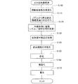
次に、上記した燃料電池10に用いられるアノード側ガス拡散層23とカソード側ガス拡散層24の製造方法と、ガス拡散層の性能評価について詳述する。この両ガス拡散層は同じ製造方法で製造されて、アノード側とカソード側に使い分けられる。まず、製造方法について説明する。図2はガス拡散層の製造方法の処理手順を示すフローチャート、図3はガス拡散層の製造に用いる拡散層製造装置100の構成を概略的に示す説明図である。
Next, a manufacturing method of the anode side
図2に示すように、アノード側ガス拡散層23およびカソード側ガス拡散層24の両ガス拡散層の製造に際しては、前駆体樹脂の溶液化(ステップS100)、押出ノズルからの押出紡糸(ステップS110)、不織布様に繊維堆積(ステップS120)の一連の処理が、図3の拡散層製造装置100にて連続的になされる。
As shown in FIG. 2, in the production of both the anode-side
拡散層製造装置100は、メルトブロー方式の押出紡糸装置であり、図3に示すように、樹脂投入部110と、樹脂押出部120と、ノズル機構部130と、織布部140とを備える。樹脂投入部110は、後述の黒鉛化までの処理を受けることで炭素繊維CFに変遷する前駆体樹脂、例えば、ピッチ、ポリアクリロニトリル、レーヨン、フェノール系樹脂等のパウダー状原材料の投入を受け、所定メッシュでのパウダーろ過と乾燥を行って、粒径調整済みのパウダー状原材料を樹脂押出部120に供給する。樹脂押出部120は、供給を受けたパウダー状原材料の前駆体樹脂を加熱して溶液化し、前駆体樹脂の溶液(前駆体樹脂溶液)をノズル機構部130に供給する(ステップS100)。この際、粘度等が調整される。
The diffusion
ノズル機構部130は、供給を受けた前駆体樹脂溶液を押出ノズル132から押し出して紡糸し、その紡糸の際には、押出ノズル132のノズル先端にエアーを吹き付けて樹脂の硬化を図る。これにより、ノズル機構部130からは、詳しくは押出ノズル132からは、織布部140の濾材シートFsに向けてスライバー状に前駆体樹脂の繊維が押し出され、前駆体樹脂繊維PFcが紡糸される(ステップS110)。ノズル機構部130は、押出ノズル132にノズル温度調整部134を備える。このノズル温度調整部134は、例えば、押出ノズル132を含む図示しない循環系での冷却水の循環流量や温度の調整とノズルを加熱する図示しないヒーター発熱調整とにより、押出ノズル132の温度を変更する。つまり、押出ノズル132は、ノズル温度が高低変更されつつ、前駆体樹脂溶液を押し出して紡糸する。
The
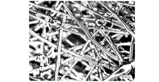
こうしたノズル温度調整は、拡散層製造装置100が有する図示しない制御装置からの制御を受けてなされる。図4はノズル温度を高低変更しつつ押出ノズル132から押出し紡糸された前駆体樹脂繊維PFcを電子顕微鏡にて撮影した図面代用写真である。図示するように、本実施例では、ノズル温度調整下での押出紡糸を図ることで、前駆体樹脂繊維PFcの表面に凹凸を付与する。この凹凸は、押出紡糸の際のノズル温度の高低設定で前駆体樹脂繊維PFcの表面に形成され、ノズル温度の高低差や高低の温度推移を調整することで、凹凸の程度や凹凸の発現頻度を調整できる。この際、ノズル先端へのエアー吹き付けにあっても、繊維表面の凹凸形成に影響することから、エアー吹き付け流量を調整することも有益である。
Such nozzle temperature adjustment is performed under the control of a control device (not shown) included in the diffusion
上記のノズル温度の高低調整は、種々の手法で行うことができ、例えば、ピッチを前駆体樹脂とした場合には、そのピッチが溶け始める軟化温度(110〜300℃)を超える温度で繰り返し高低変更させるようにすればよい。こうしたノズル温度調整により、表面に凹凸を有する前駆体樹脂繊維PFcを押出紡糸できる。この場合、ノズル温度を一定としたまま、押出ノズル132からの押出紡糸を行うことで、繊維表面に凹凸のない、或いは極小さな凹凸しか存在しないほぼ円形断面の前駆体樹脂繊維PFcを押出紡糸できる。
The above-described adjustment of the nozzle temperature can be performed by various methods. For example, when the pitch is a precursor resin, the nozzle temperature is repeatedly raised and lowered at a temperature exceeding the softening temperature (110 to 300 ° C.) at which the pitch starts to melt. Change it. By adjusting the nozzle temperature, the precursor resin fiber PFc having irregularities on the surface can be extruded and spun. In this case, by performing extrusion spinning from the
織布部140は、巻取ローラー142と、一対の補助ローラー144とを備え、巻取ローラー142でのシート巻き取りにより、補助ローラー144の間において濾材シートFsを所定のテンションを掛けて保持する。そして、織布部140は、テンションが掛けられた濾材シートFsの上面を、織布部FBとする。濾材シートFsは、織布部FBに向けて紡糸された繊維、或いは織布部FBでの織布家庭にある繊維から、余剰の溶媒等を吸着する。
The woven
ノズル機構部130は、押出ノズル132を図3の紙面方向に並べて列状に備え、その列状の押出ノズル132を紙面奥側から手前側、および図における左右方向、即ち送り方向に対する上下流側に移動させる。このノズル移動は、濾材シートFsに対して種々の方向になされる。そして、押出ノズル132は、こうした2次元的なノズル移動に伴って織布部FBの濾材シートFsに前駆体樹脂溶液を押出紡糸し、濾材シートFsは図示する送り出し方向に移動するので、紡糸済み繊維が織布部FBにて不織布様に堆積する(ステップS120)。
The
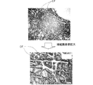
ノズル機構部130は、押出ノズル132からの押出紡糸を所定スパンで繰り返すので、各スパンにおいて、紡糸済み繊維は、不織布様に堆積しつつ、その不織布様の堆積箇所がシート状に延びる。これにより、紡糸済み繊維を不織布様に堆積させたシート状の拡散層中間品CFFcが、濾材シートFsの上面に得られる(ステップS130)。図5は得られた拡散層中間品CFFcを異なる倍率で表層側から電子顕微鏡撮影した図面代用写真である。この図5における左側の写真は、右側写真における繊維交差部位を5倍に拡大した写真画像である。図示するように、得られた拡散層中間品CFFcは、前駆体樹脂繊維PFcが不織布様に堆積している。この場合、倍率を更に高めれば、拡散層中間品CFFcを構成する個々の前駆体樹脂繊維PFcがその繊維表面に既述した凹凸を有する様子が映し出される(図4参照)。この拡散層中間品CFFcは、濾材シートFsと共に下流に送り出され、巻取ローラー142の手前において、剥離される。この剥離された拡散層中間品CFFcがその後の不融化、炭化および黒鉛化に処される。
Since the
得られた拡散層中間品CFFcは、図示しない不融化炉に運び込まれ、バッチ的に不融化処理に処される(ステップS140)。不融化は、酸素による酸化、酸化縮合、脱水素縮合等の種々の手法で行うことができる。本実施例では、この不融化を行うに当たり、用いた前駆体樹脂の不融化が完遂する前の状態とした。例えば、ピッチを前駆体樹脂とした場合には、そのピッチの不融化が完遂し得る250〜400℃の温度より低温の環境下で不融化を行う。或いは、この温度でピッチの不融化が完遂し得る100〜1000minより短い時間で不融化を行うようにした。図6は上記の不融化処理後の拡散層中間品CFFcをその表層側から電子顕微鏡撮影した図面代用写真である。図示するように、不融化を受けた拡散層中間品CFFcでは、前駆体樹脂繊維PFcの交差箇所や重なった箇所、或いは繊維端部が周辺繊維と接触している箇所で、繊維の融着が起きている。この融着箇所は、図において点線にて示されており、繊維の交差箇所や重なった箇所、繊維端部の接触箇所では、熱の集中が起きやすいことから、上記の不融化においても、繊維の融着が起きることになる。この融着は、前駆体樹脂繊維PFcの原材料樹脂(炭素繊維CFの前駆体樹脂)そのもので起きることから、後述の炭化および黒鉛化の後には、上記の融着部位は、炭素繊維CFと同じ黒鉛構造となる。 The obtained diffusion layer intermediate product CFFc is carried into an infusible furnace (not shown) and batch-processed into an infusible treatment (step S140). Infusibilization can be performed by various methods such as oxidation with oxygen, oxidative condensation, and dehydrogenative condensation. In this example, the infusibilization was performed before the infusibilization of the precursor resin used was completed. For example, when pitch is used as the precursor resin, the infusibilization is performed in an environment at a temperature lower than a temperature of 250 to 400 ° C. at which the infusibilization of the pitch can be completed. Alternatively, the infusibilization is performed in a time shorter than 100 to 1000 min at which the infusibilization of pitch can be completed at this temperature. FIG. 6 is a drawing-substituting photograph in which the diffusion layer intermediate product CFFc after the infusibilization treatment is taken with an electron microscope from the surface layer side. As shown in the figure, in the diffusion layer intermediate product CFFc that has undergone infusibilization, the fusion of the fibers occurs at the intersection or overlap of the precursor resin fibers PFc or where the fiber ends are in contact with the surrounding fibers. stay up. This fusion location is indicated by a dotted line in the figure, and heat concentration is likely to occur at the intersection of the fibers, the overlapping location, and the contact location at the end of the fiber. The fusion of will occur. Since this fusion occurs in the raw material resin (precursor resin of carbon fiber CF) of the precursor resin fiber PFc itself, after the carbonization and graphitization described later, the above fusion site is the same as that of the carbon fiber CF. It has a graphite structure.
上記の不融化を受けた拡散層中間品CFFcは、図示しない炭化炉に運び込まれ、不活性ガス環境下でバッチ的に炭化処理に処される(ステップS150)。この炭化処理は、用いた前駆体樹脂を炭化する既存の炭化処理と変わるものではなく、炭化温度や昇温速度、炭化処理時間等は既存手法と同じである。炭化処理後は、炭化炉での処理温度を黒鉛化処理温度に高めることで、或いは、図示しない黒鉛化炉に運び込んで、炭化済み拡散層中間品CFFcを、不活性ガス環境下でバッチ的に黒鉛化処理し(ステップS160)、その後、冷却養生する(ステップS170)。上記の黒鉛化処理にあっても、既存の黒鉛化処理と変わるものではなく、黒鉛化温度や昇温速度、黒鉛化処理時間等は既存手法と同じである。不融化を受けた拡散層中間品CFFcを構成する前駆体樹脂繊維PFcは、繊維表面に凹凸を有したまま、ステップS150〜160の炭化・黒鉛化を経て炭素繊維CFに変遷する。よって、冷却養生後には、繊維表面に凹凸を有する炭素繊維CFが層厚方向に堆積した薄葉シート状のガス拡散層が得られ、アノード側ガス拡散層23とカソード側ガス拡散層24に使い分けられる。図7は冷却養生後に得られた最終製品たるガス拡散層をその表層側から電子顕微鏡撮影した図面代用写真である。炭素繊維CFは、上記の不融化により融着した部位を含め、肉眼観察において黒鉛化済みであることが確認できたほか、電子顕微鏡写真でも、黒鉛化済みであることが確認できた。また、肉眼観察および指先での触感において、ガス拡散層表層に炭素繊維CFの先端が突出したことで起きるいわゆる毛羽についても、観察されなかった。このことは、炭素繊維CFの先端がその周囲の炭素繊維CFに接触して既述した溶融と結着、その後の黒鉛化がなされていることを意味する。
The diffusion layer intermediate product CFFc that has undergone the above infusibilization is carried into a carbonization furnace (not shown) and is subjected to a carbonization process batchwise in an inert gas environment (step S150). This carbonization treatment is not different from the existing carbonization treatment for carbonizing the used precursor resin, and the carbonization temperature, the heating rate, the carbonization treatment time, and the like are the same as those of the existing method. After the carbonization treatment, the carbonization furnace intermediate temperature CFFc is batch-treated in an inert gas environment by raising the treatment temperature in the carbonization furnace to the graphitization treatment temperature or by bringing it into a graphitization furnace (not shown). Graphitization is performed (step S160), and then cooling curing is performed (step S170). Even in the above graphitization treatment, it is not different from the existing graphitization treatment, and the graphitization temperature, the heating rate, the graphitization treatment time, etc. are the same as those in the existing method. The precursor resin fiber PFc constituting the diffusion layer intermediate product CFFc that has undergone infusibilization changes to carbon fiber CF through carbonization and graphitization in steps S150 to S160 while the fiber surface has irregularities. Therefore, after cooling and curing, a thin sheet-like gas diffusion layer in which carbon fibers CF having irregularities on the fiber surface are deposited in the layer thickness direction is obtained, and can be used separately for the anode side
得られたアノード側ガス拡散層23とカソード側ガス拡散層24は、図1に示すように、MEAのアノード21に接合された上で、MEAと共にガスセパレーター25とガスセパレーター26で挟持され、単セル15、延いては燃料電池10を構成する。
As shown in FIG. 1, the obtained anode side
次に得られたガス拡散層の性能評価について説明する。性能評価の対象となる実施例品は、上記したステップS100〜170を経て製造されたガス拡散層であり、比較例品は、黒鉛化済みの炭素繊維CFをバインダーにより結着させつつ炭素繊維CFを層厚方向に堆積した既存のガス拡散層である。図8は比較例品のガス拡散層と実施例品のガス拡散層のそれぞれを構成する炭素繊維CFの結着の様子を平面視して模式的に示す説明図である。図示するように、比較例品は、炭素繊維CFの交差箇所がバインダーにて結着されているのに対し、実施例品では、炭素繊維CFの交差箇所は、炭素繊維CFの前駆体樹脂の融着を経て黒鉛化して結着されている。こうした結着は、次のように起きる。図9は比較例品と実施例品における炭素繊維CFの結着に至る過程を側面視方向から模式的に示す説明図である。この図9では、図における上下の炭素繊維CFの間に、紙面手前から奥側に炭素繊維CFが延びて、炭素繊維CFが交差している様子を模式的に示している。 Next, performance evaluation of the obtained gas diffusion layer will be described. An example product for performance evaluation is a gas diffusion layer manufactured through the above-described steps S100 to 170, and a comparative example product is carbon fiber CF while binding graphitized carbon fiber CF with a binder. Is an existing gas diffusion layer deposited in the layer thickness direction. FIG. 8 is an explanatory view schematically showing a state of binding of the carbon fibers CF constituting each of the gas diffusion layer of the comparative example product and the gas diffusion layer of the example product in a plan view. As shown in the figure, in the comparative product, the intersections of the carbon fibers CF are bound by a binder, whereas in the example products, the intersections of the carbon fibers CF are the precursor resin of the carbon fibers CF. It is graphitized and bonded after fusing. Such binding occurs as follows. FIG. 9 is an explanatory view schematically showing the process leading to the binding of the carbon fiber CF in the comparative example product and the example product from the side view direction. FIG. 9 schematically shows that the carbon fiber CF extends between the upper and lower carbon fibers CF in FIG.
図9に示すように、比較例品では、バインダーによる結着を図るに当たり、層厚を薄くするようプレスによる面圧を掛ける。この面圧を受けて炭素繊維CFが接触もしくは近接すると、その箇所がバインダーにて結着される。ところが、面圧を受けない炭素繊維CFもしくは面圧を受けても周囲の炭素繊維CFに接触もしくは近接しない炭素繊維CFは、バインダーによる結着がなされず、ある程度、フリーの状態となる。その一方、実施例品では、不融化(図2:ステップS140)を受け、この際にはプレスによる面圧は炭素繊維CF、詳しくは、前駆体樹脂繊維PFcには作用しない。ところが、前駆体樹脂繊維PFcは、不融化の際の熱を受けて伸張、曲がり等の変形を起こして、その繊維軌跡を変え、周囲の前駆体樹脂繊維PFcに接触もしくは近接する。つまり、実施例品では、炭素繊維CF、詳しくは前駆体樹脂繊維PFcの接触もしくは近接が起きる箇所が増え、当該箇所では、樹脂の融着が起き、その融着箇所は黒鉛化して(ステップS150〜160)、炭素繊維CFを強固に結着する。しかも、実施例品では、炭素繊維CFは図4に示したように繊維表面に凹凸を有することから、繊維同士の接触がこの凹凸で起きていることにより、上記の融着と相まって、より強固に結着することになる。 As shown in FIG. 9, in the comparative product, a surface pressure by a press is applied so as to reduce the layer thickness when binding with the binder. When the carbon fiber CF is brought into contact with or in proximity to the surface pressure, the portion is bound by the binder. However, the carbon fibers CF that are not subjected to the surface pressure or the carbon fibers CF that are not in contact with or close to the surrounding carbon fibers CF even when subjected to the surface pressure are not bound by the binder and are in a free state to some extent. On the other hand, in the example product, infusibilization (FIG. 2: step S140) was performed, and in this case, the surface pressure by the press does not act on the carbon fiber CF, specifically, the precursor resin fiber PFc. However, the precursor resin fiber PFc undergoes deformation such as stretching and bending upon receiving heat at the time of infusibilization, changes its fiber trajectory, and contacts or approaches the surrounding precursor resin fiber PFc. That is, in the example product, the number of locations where the carbon fiber CF, specifically, the precursor resin fiber PFc is brought into contact or close to each other increases, and in this location, resin fusion occurs, and the fusion location is graphitized (step S150). To 160), the carbon fiber CF is firmly bound. In addition, in the example product, the carbon fiber CF has irregularities on the fiber surface as shown in FIG. 4, and the contact between the fibers is caused by the irregularities, which is combined with the above fusion and becomes stronger. Will be bound to.
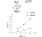
こうした繊維結着の様子が相違する比較例品と実施例品とについて、ガス透過性評価を行った。図10はガス拡散層の層厚方向のガス透過度を測定する様子とその結果を比較例品と実施例品とについてプロットしたグラフを示す説明図、図11はガス拡散層の層内におけるガス透過度を測定する様子とその結果を比較例品と実施例品とについてプロットしたグラフを示す説明図である。この場合、層厚方向のガス透過度測定については、ガス拡散層側面を目張りした上で、図10に示すように、加圧エアー(1.8MPa)をガス拡散層の一方表面から吹き付け、その透過エアーの圧損を求め、圧損と加圧エアー吹出流量とを対応付けた。ガス拡散層層内のガス透過度測定については、ガス拡散層表裏の一方表面を目張りした上で、図11に示すように、加圧エアー(1.8MPa)をガス拡散層の他方表面から吹き付け、その透過エアーの圧損を求め、圧損と加圧エアー吹出流量とを対応付けた。 The gas permeability evaluation was performed about the comparative example goods and the example goods from which the mode of such fiber binding differs. FIG. 10 is an explanatory diagram showing a state in which the gas permeability in the layer thickness direction of the gas diffusion layer is measured, and a graph in which the result is plotted for the comparative example product and the example product, and FIG. 11 is the gas in the gas diffusion layer. It is explanatory drawing which shows the graph which plotted the mode which measured the transmittance | permeability, and the result about the comparative example goods and the Example goods. In this case, for measuring the gas permeability in the layer thickness direction, after the side surface of the gas diffusion layer is stretched, pressurized air (1.8 MPa) is blown from one surface of the gas diffusion layer as shown in FIG. The pressure loss of the permeated air was determined, and the pressure loss was associated with the pressurized air blowing flow rate. For measuring the gas permeability in the gas diffusion layer, as shown in FIG. 11, after spraying the front and back surfaces of the gas diffusion layer, pressurized air (1.8 MPa) is blown from the other surface of the gas diffusion layer. Then, the pressure loss of the permeated air was determined, and the pressure loss was associated with the pressurized air blowing flow rate.
図10〜図11に示すように、実施例品は、低流量から高流量に亘って、比較例品の3倍程度のガス透過性を有することが判明した。このため、実施例品のガス拡散層であるアノード側ガス拡散層23とカソード側ガス拡散層24とを有する燃料電池10では、両ガス拡散層での高いガス透過性により、MEAへのガス拡散が高まり、発電能力が高まると想定される。また、カソード側ガス拡散層24では、生成水の排水性が高まり、アノード側ガス拡散層23にあっても、ガス加湿用に含有された水蒸気成分の排出も高まることから、フラッディングの抑制、延いては低温始動性も高まると想定される。
As shown in FIGS. 10 to 11, it was found that the example product has a gas permeability about three times that of the comparative example product from a low flow rate to a high flow rate. For this reason, in the
図8〜図9で説明したように、実施例品では、炭素繊維CFの接触もしくは近接が起きる箇所が増えた上で、当該箇所での不融化に伴う樹脂融着と、その融着箇所の黒鉛化による炭素繊維CFの強固な結着が起きる。このため、実施例品では、炭素繊維CFで形成されるガス拡散層内の空隙が潰れたり閉塞しないようになるので、図10〜図11に示すように、高圧・高流量でのエアー吹き付けに対しても高いガス透過性が得られるからである。これに加え、実施例品のガス拡散層は、これを構成する炭素繊維CFのそれぞれが、繊維表面に凹凸を有する。よって、炭素繊維CFが力を受けて周囲の炭素繊維CFに接触しても、エアー吹出と関連付ければ、高圧でのエアー吹き付けにより、その圧を受けて炭素繊維CFが力を受けて周囲の炭素繊維CFに接触しても、接触以降において、その接触状態は凹凸により維持され、炭素繊維CF同士の滑りは摩擦力の増大により起き難くなる。この点からも、実施例品のガス拡散層によれば、高圧・高流量でのエアー吹き付けに対しても高いガス透過性が得られることになる。 As described with reference to FIGS. 8 to 9, in the example product, the number of locations where the contact or proximity of the carbon fiber CF occurs increases, and the resin fusion accompanying infusibilization at the location, and the location of the fusion location The carbon fiber CF is strongly bound by graphitization. For this reason, in the example product, the voids in the gas diffusion layer formed of the carbon fiber CF are not crushed or closed, so as shown in FIGS. 10 to 11, for air blowing at high pressure and high flow rate. This is because high gas permeability can be obtained. In addition to this, each of the carbon fibers CF constituting the gas diffusion layer of the example product has irregularities on the fiber surface. Therefore, even if the carbon fiber CF receives a force and comes into contact with the surrounding carbon fiber CF, if the carbon fiber CF is associated with the air blowing, the carbon fiber CF receives the force and receives the pressure by the air blowing at a high pressure. Even after contacting the carbon fiber CF, the contact state is maintained by the unevenness after the contact, and slippage between the carbon fibers CF hardly occurs due to an increase in frictional force. Also from this point, according to the gas diffusion layer of the example product, high gas permeability can be obtained even when air is blown at a high pressure and a high flow rate.
次に、ガス拡散層のヘタリやクリープの抑制の上での指標となり得る撓みについて説明する。図12はガス拡散層の撓み程度を測定する様子とその結果を比較例品と実施例品とについてプロットしたグラフを示す説明図である。この撓み測定に当たっては、次の状況を想定した。アノード側ガス拡散層23やカソード側ガス拡散層24は、図1に示すように、ガスセパレーター25やガスセパレーター26に当接する。よって、セパレーターにおけるセル内燃料ガス流路47やセル内酸化ガス流路48とほぼ同寸の凹条溝を有する治具に、図12に示すように、実施例品と比較例品のガス拡散層を載置して溝上方から荷重を掛けつつ、撓み込み量を求め、これを荷重(先端面圧)と対応付けた。
Next, a description will be given of the deflection that can serve as an index for suppressing the settling and creep of the gas diffusion layer. FIG. 12 is an explanatory view showing a graph in which the degree of bending of the gas diffusion layer is measured and the results are plotted for the comparative example product and the example product. The following situation was assumed for this deflection measurement. The anode-side
図12に示すように、実施例品は、荷重を受けることで溝内に撓み込む撓み込み量が、比較例品より小さい。このため、継続して荷重を受けた場合のヘタリやクリープは起きがたくなるので、実施例品では、ガス拡散層の層状形態を維持、或いは、層状形態の変化を抑制できることになる。このことは、図8〜図9で説明したように、実施例品では、炭素繊維CFの接触もしくは近接が起きる箇所が増えた上で、当該箇所での不融化に伴う樹脂融着と、その融着箇所の黒鉛化による炭素繊維CFの強固な結着が起きることで、説明できる。 As shown in FIG. 12, the example product has a smaller amount of bending into the groove by receiving a load than the comparative product. For this reason, since settling and creep are less likely to occur when the load is continuously received, the layered form of the gas diffusion layer can be maintained or the change in the layered form can be suppressed in the example product. As described with reference to FIGS. 8 to 9, in the example product, after the number of places where the contact or proximity of the carbon fiber CF occurs, the resin fusion accompanied by the infusibilization in the place, This can be explained by the strong binding of the carbon fiber CF due to graphitization of the fused part.
次に、変形例について説明する。図13は変形例の炭素繊維CFの端面を電子顕微鏡撮影した図面代用写真である。この変形例の炭素繊維CFは、繊維内部に複数の中空部を有する中空繊維(図13(A))、或いは、繊維中央に中空部を有する中空繊維(図13(B))とされている。これら中空繊維としての炭素繊維CFにてアノード側ガス拡散層23やカソード側ガス拡散層24のガス拡散層を形成するには、ノズル機構部130にて押出紡糸する際の押出ノズル132を中空繊維紡糸対応のノズルとすればよい。図14は変形例の中空繊維状の炭素繊維CFを得るための押出ノズル132の構成を模式的に示す説明図である。繊維内部に複数の中空部を有する中空繊維とするには(図13(A))、押出ノズル132を樹脂押出孔に押出規制駒136を複数配置したノズルとする(図14(A))。繊維中央に中空部を有する中空繊維とするには(図13(B))、押出ノズル132を樹脂押出孔の中央に押出規制駒136をノズルとする(図14(B))。そして、このように押出規制駒136を有する押出ノズル132から前駆体樹脂溶液を押出紡糸すると、既述したようにノズル温度変化に伴って繊維表面に凹凸を有した上で、押出規制駒136により中空繊維とされた前駆体樹脂繊維PFcが押出紡糸される。こうして紡糸された前駆体樹脂繊維PFcを、図2のステップS120以降の処理に処すことで、中空繊維でありながら繊維表面に凹凸を有する炭素繊維CFが層厚方向に堆積したアノード側ガス拡散層23やカソード側ガス拡散層24を得ることができる。
Next, a modified example will be described. FIG. 13 is a drawing-substituting photograph in which the end face of the carbon fiber CF of the modification is taken with an electron microscope. The carbon fiber CF of this modification is a hollow fiber having a plurality of hollow portions inside the fiber (FIG. 13A) or a hollow fiber having a hollow portion at the center of the fiber (FIG. 13B). . In order to form the gas diffusion layers of the anode-side
この変形例では、炭素繊維CFが中空繊維であることから、ガス拡散層を構成する炭素繊維CF自体で、繊維縮径方向の力に対してのバネ性を発揮できる。よって、表面に凹凸を備えた上で中空繊維とされた炭素繊維CFで形成されたガス拡散層では、ガス拡散層の層状形態の維持や層状形態の変化の抑制の実効性をより高めることができる。加えて、炭素繊維CFの内部の中空部をガスや水が流れることから、ガス拡散性や水の排水性の確保の上でも有益となる。 In this modified example, since the carbon fiber CF is a hollow fiber, the carbon fiber CF itself constituting the gas diffusion layer can exhibit a spring property with respect to a force in the fiber contraction direction. Therefore, in the gas diffusion layer formed of carbon fiber CF having hollow surfaces and having irregularities on the surface, it is possible to further increase the effectiveness of maintaining the layered form of the gas diffusion layer and suppressing the change in the layered form. it can. In addition, since gas and water flow through the hollow portion inside the carbon fiber CF, it is beneficial for ensuring gas diffusibility and water drainage.
上記の変形例では、押出規制駒136の大きさや配置を変えることで、表面に凹凸を備えた炭素繊維CFの空孔率を30%以上としたので、高い実効性でバネ性を発揮できると共に、ガス拡散性や水の排水性についても、これを高めることができる。そして、表面に凹凸を備えた炭素繊維CFの空孔率を50%以以下としたので、中空繊維としての炭素繊維CFの形状を維持でき、ガス拡散層の不用意なヘタリを回避できる。そして、炭素繊維CFの中空部は、断熱性を発揮することから、この変形例のアノード側ガス拡散層23とカソード側ガス拡散層24を有する単セル15、延いては燃料電池10においては、低温環境下での発電性能の低下を抑制できる。
In the above modification, by changing the size and arrangement of the
図15は別の変形例の拡散層中間品CFFcの製造過程を示す説明図である。この変形例は、拡散層中間品CFFcを2層構造とした点に特徴がある。図示するように、変形例の拡散層中間品CFFcは、第1拡散層中間品CFFc1と第2拡散層中間品CFFc2とを、それぞれの第1織布部FB1〜FB2で形成した上で、第2織布部FB2において積層し、2層の拡散層中間品CFFcとする。この第1拡散層中間品CFFc1と第2拡散層中間品CFFc2のそれぞれは、第1押出ノズル1321或いは第2押出ノズル1322から前駆体樹脂溶液を押出紡糸して不織布様に堆積したものである。第1押出ノズル1321は、ノズル温度を変更しないで前駆体樹脂溶液を押出紡糸する、或いは、ノズル温度の高低差や温度推移を小さくして前駆体樹脂溶液を押出紡糸する。このため、第1押出ノズル1321から押出紡糸された前駆体樹脂繊維PFcは、その繊維表面に凹凸を有しない繊維、或いは凹凸が小さな繊維となって、第1拡散層中間品CFFc1を形成する。その一方、第2押出ノズル1322は、既述した132と同様のノズル温度の高低変更を行いつつ変更や前駆体樹脂溶液を押出紡糸するので、その前駆体樹脂繊維PFcは、繊維表面に第1押出ノズル1321による前駆体樹脂繊維PFcより大きな凹凸を備えて、第2拡散層中間品CFFc2を形成する。こうして得られた第1拡散層中間品CFFc1と第2拡散層中間品CFFc2は、第2織布部FB2にて重なることで、2層構造の拡散層中間品CFFcとなる。
FIG. 15 is an explanatory view showing a manufacturing process of a diffusion layer intermediate product CFFc of another modified example. This modification is characterized in that the diffusion layer intermediate product CFFc has a two-layer structure. As shown in the figure, the diffusion layer intermediate product CFFc of the modified example is formed by forming the first diffusion layer intermediate product CCFc1 and the second diffusion layer intermediate product CCFc2 with the respective first woven fabric portions FB1 to FB2. Two woven fabric portions FB2 are laminated to form a two-layer diffusion layer intermediate product CFFc. Each of the first diffusion layer intermediate product CCFc1 and the second diffusion layer intermediate product CCFc2 is obtained by extruding a precursor resin solution from the
この2層構造の拡散層中間品CFFcは、その後の不融化、炭化および黒鉛化に処されて、炭素繊維CFが層厚方向に堆積したガス拡散層となる。この炭素繊維CFによるガス拡散層であっても、炭素繊維CFに変遷する前の前駆体樹脂繊維PFcの繊維表面の状況が反映する。このため、第1拡散層中間品CFFc1に相当する一方のガス拡散層表層部では、これを構成する炭素繊維CFは、繊維表面に凹凸を備えない、或いは小さな凹凸しか備えない。その一方、第2拡散層中間品CFFc2に相当する他方のガス拡散層表層部では、これを構成する炭素繊維CFは、繊維表面に凹凸を備える。つまり、この変形例の拡散層中間品CFFcから形成されたガス拡散層は、拡散層表裏において、炭素繊維CFの表面の凹凸の状況を異なる物とし、一方を繊維表面に凹凸を備えない、或いは小さな凹凸しか備えないようにする。この変形例の拡散層中間品CFFcから形成されたアノード側ガス拡散層23とカソード側ガス拡散層24を用いた単セル15では、次の利点がある。
The diffusion layer intermediate product CFFc of this two-layer structure is subjected to subsequent infusibilization, carbonization and graphitization to become a gas diffusion layer in which carbon fibers CF are deposited in the layer thickness direction. Even the gas diffusion layer made of the carbon fiber CF reflects the state of the fiber surface of the precursor resin fiber PFc before the transition to the carbon fiber CF. For this reason, in one gas diffusion layer surface layer portion corresponding to the first diffusion layer intermediate product CFFc1, the carbon fiber CF constituting this has no unevenness on the fiber surface or only small unevenness. On the other hand, in the other gas diffusion layer surface layer portion corresponding to the second diffusion layer intermediate product CFFc2, the carbon fiber CF constituting this has irregularities on the fiber surface. That is, the gas diffusion layer formed from the diffusion layer intermediate product CFFc of this modified example has different surface irregularities on the surface of the carbon fiber CF on the front and back of the diffusion layer, and one of them does not have irregularities on the fiber surface, or Try to have only small irregularities. The
図1に示す単セル15において、アノード側ガス拡散層23とカソード側ガス拡散層24とを、第1拡散層中間品CFFc1に相当する表層側がMEAのアノード21、カソード22に接合するようにする。そうすると、アノード21やカソード22には、図15に示すように、繊維表面に凹凸のない或いは小さな凹凸しか有しない炭素繊維CFが接合することになる。このため、MEAに炭素繊維表面の凹凸が接合することで起きるアノード21やカソード22、および電解質膜20にメカニカルなダメージを与えないようにできることから、MEA、延いては単セル15、燃料電池10としての耐久性を高めることができる。
In the
図16はまた別の変形例の拡散層中間品CFFcの製造過程を示す説明図である。この変形例は、拡散層中間品CFFcを3層構造とした点に特徴がある。図示するように、変形例の拡散層中間品CFFcは、第1拡散層中間品CFFc1と第2拡散層中間品CFFc2と第3拡散層中間品CFFc3を、それぞれの第1織布部FB1〜FB3で形成した上で、第2織布部FB3において積層し、3層の拡散層中間品CFFcとする。この第1拡散層中間品CFFc1と第2拡散層中間品CFFc2のそれぞれは、図15の変形例における第1押出ノズル1321或いは第2押出ノズル1322から前駆体樹脂溶液を押出紡糸して不織布様に堆積したものである。この変形例では、更に第3押出ノズル1323を備え、このノズルを、ノズル温度を変更しないで前駆体樹脂溶液を押出紡糸する、或いは、ノズル温度の高低差や温度推移を小さくして前駆体樹脂溶液を押出紡糸するノズルとする。このため、この変形例の3層構造の拡散層中間品CFFcの不融化、炭化および黒鉛化を経て得られたガス拡散層では、その内層側を占める第2拡散層中間品CFFc2に相当するガス拡散層部位の炭素繊維CFは、その繊維表面の凹凸を、表裏の表層側を占める第1拡散層中間品CFFc1および第3拡散層中間品CFFc3に相当するガス拡散層部位の炭素繊維CFより、大きくしている。つまり、この変形例の拡散層中間品CFFcから形成されたガス拡散層は、ガス拡散層表裏においては、炭素繊維CFの繊維表面に凹凸を備えない、或いは小さな凹凸しか備えないようにする。この変形例の拡散層中間品CFFcから形成されたアノード側ガス拡散層23とカソード側ガス拡散層24を用いた単セル15では、次の利点がある。
FIG. 16 is an explanatory view showing the manufacturing process of the diffusion layer intermediate product CFFc of another modified example. This modification is characterized in that the diffusion layer intermediate product CFFc has a three-layer structure. As shown in the drawing, the diffusion layer intermediate product CFFc of the modified example includes a first diffusion layer intermediate product CCFc1, a second diffusion layer intermediate product CCFc2, and a third diffusion layer intermediate product CCFc3, and the first woven fabric portions FB1 to FB3. And then laminated in the second woven fabric portion FB3 to form a three-layer diffusion layer intermediate product CFFc. Each of the first diffusion layer intermediate product CCFc1 and the second diffusion layer intermediate product CCFc2 is formed into a nonwoven fabric by extrusion-spinning the precursor resin solution from the
図1に示す単セル15において、アノード側ガス拡散層23とカソード側ガス拡散層24とは、第1拡散層中間品CFFc1に相当する表層側でMEAのアノード21、カソード22に接合し、第3拡散層中間品CFFc3に相当する表層側でガスセパレーター25、ガスセパレーター26に接合する。このため、既述したように、MEAに炭素繊維表面の凹凸が接合することで起きるアノード21やカソード22、および電解質膜20にメカニカルなダメージを与えないようにできる。加えて、ガスセパレーター25やガスセパレーター26に対しては、図16に示すように、繊維表面に凹凸のない或いは小さな凹凸しか有しない炭素繊維CFを接合させるので、セパレーターとの接触を確保して、接触抵抗の増大を抑制できる。この結果、この変形例のガス拡散層によれば、セパレーターとの接触抵抗低減により、単セル15、延いては燃料電池10としての発電能力を高めることができる。
In the
以上、本発明の実施の形態について説明したが、本発明はこのような実施の形態になんら限定されるものではなく、その要旨を逸脱しない範囲内において種々なる態様での実施が可能である。例えば、実施例では、押出ノズル132を用いたメルトブロー方式の押出紡糸を採用したが、エレクトロスピニング方式の押出紡糸を行うようにすることもできる。
Although the embodiments of the present invention have been described above, the present invention is not limited to such embodiments, and can be implemented in various modes without departing from the scope of the present invention. For example, in the embodiment, melt blow type extrusion spinning using the
10…燃料電池
15…単セル
20…電解質膜
21…アノード
22…カソード
23…アノード側ガス拡散層
24…カソード側ガス拡散層
25…ガスセパレーター
26…ガスセパレーター
47…セル内燃料ガス流路
48…セル内酸化ガス流路
100…拡散層製造装置
110…樹脂投入部
120…樹脂押出部
130…ノズル機構部
132…押出ノズル
1321…第1押出ノズル
1322…第2押出ノズル
1323…第3押出ノズル
134…ノズル温度調整部
136…押出規制駒
140…織布部
142…巻取ローラー
144…補助ローラー
CFFc…拡散層中間品
CFFc1…第1拡散層中間品
CFFc2…第2拡散層中間品
CFFc3…第3拡散層中間品
CF…炭素繊維
Fs…濾材シート
FB…織布部
FB1…第1織布部
FB2…第2織布部
FB3…第3織布部
PFc…前駆体樹脂繊維
DESCRIPTION OF
Claims (10)
炭素繊維を層厚方向に堆積して形成され、
前記炭素繊維は、繊維表面に凹凸を有し、
前記ガス拡散層の少なくとも一方の表層側を占める前記炭素繊維は、該表層側以外の部位を占める前記炭素繊維より、繊維表面の前記凹凸が抑制されている
ガス拡散層。 A gas diffusion layer for a fuel cell,
Formed by depositing carbon fibers in the layer thickness direction,
The carbon fiber has irregularities on the fiber surface ,
The said carbon fiber which occupies the surface layer side of at least one of the said gas diffusion layer is a gas diffusion layer by which the said unevenness | corrugation of the fiber surface is suppressed rather than the said carbon fiber which occupies site | parts other than this surface layer side .
炭素繊維を層厚方向に堆積して形成され、
前記炭素繊維は、繊維表面に凹凸を有し、
前記層厚方向に前記炭素繊維を3層以上の多層に堆積した多層構造を備え、内層側を占める前記炭素繊維は、表層側を占める前記炭素繊維より、繊維表面の前記凹凸が顕在化されている
ガス拡散層。 A gas diffusion layer for a fuel cell,
Formed by depositing carbon fibers in the layer thickness direction,
The carbon fiber has irregularities on the fiber surface,
The carbon fiber having a multilayer structure in which the carbon fibers are deposited in a multilayer of three or more layers in the layer thickness direction, and the carbon fiber occupying the inner layer side has the irregularities on the fiber surface revealed more than the carbon fiber occupying the surface layer side. Ru
Gas diffusion layer.
電解質膜の両膜面に電極を接合した膜電極接合体に、ガス拡散層を接合して備え、
該ガス拡散層は、繊維表面に凹凸を有する炭素繊維を層厚方向に堆積して形成され、
前記ガス拡散層の少なくとも一方の表層側を占める前記炭素繊維は、該表層側以外の部位を占める前記炭素繊維より、繊維表面の前記凹凸が抑制されている
燃料電池。 A fuel cell,
A membrane electrode assembly, in which electrodes are joined to both membrane surfaces of the electrolyte membrane, is provided with a gas diffusion layer joined,
The gas diffusion layer is formed by depositing carbon fibers having irregularities on the fiber surface in the layer thickness direction ,
The said carbon fiber which occupies at least one surface layer side of the said gas diffusion layer is a fuel cell by which the said unevenness | corrugation of the fiber surface is suppressed rather than the said carbon fiber which occupies site | parts other than this surface layer side .
電解質膜の両膜面に電極を接合した膜電極接合体に、ガス拡散層を接合して備え、 A membrane electrode assembly, in which electrodes are joined to both membrane surfaces of the electrolyte membrane, is provided with a gas diffusion layer joined,
該ガス拡散層は、繊維表面に凹凸を有する炭素繊維を層厚方向に堆積して形成されていると共に、前記層厚方向に前記炭素繊維を3層以上の多層に堆積した多層構造を備え、内層側を占める前記炭素繊維は、表層側を占める前記炭素繊維より、繊維表面の前記凹凸が顕在化されている The gas diffusion layer is formed by depositing carbon fibers having irregularities on the fiber surface in the layer thickness direction, and has a multilayer structure in which the carbon fibers are deposited in a multilayer of three or more layers in the layer thickness direction, In the carbon fiber occupying the inner layer side, the unevenness on the fiber surface is more obvious than the carbon fiber occupying the surface layer side.
燃料電池。 Fuel cell.
炭素繊維の前駆体樹脂の溶液を押出ノズルから押し出して紡糸し、紡糸済み繊維を不織布様に堆積させて拡散層中間品を形成し、
該拡散層中間品を形成する前記紡糸済み繊維を不融化した後に、該繊維を黒鉛化し、
前記押出ノズルからの前記溶液の押出紡糸に際して、前記押出ノズルのノズル温度を変更しつつ前記溶液を前記押出ノズルから押し出して紡糸する
燃料電池用のガス拡散層の製造方法。 A method for producing a gas diffusion layer for a fuel cell, comprising:
A carbon fiber precursor resin solution is extruded from an extrusion nozzle and spun, and the spun fiber is deposited like a nonwoven fabric to form a diffusion layer intermediate product.
After infusibilizing the spun fiber forming the diffusion layer intermediate, the fiber is graphitized,
A method of producing a gas diffusion layer for a fuel cell, wherein the solution is extruded from the extrusion nozzle and spun while changing the nozzle temperature of the extrusion nozzle during extrusion spinning of the solution from the extrusion nozzle.
Priority Applications (6)
| Application Number | Priority Date | Filing Date | Title |
|---|---|---|---|
| JP2012024714A JP5592906B2 (en) | 2012-02-08 | 2012-02-08 | GAS DIFFUSION LAYER FOR FUEL CELL AND FUEL CELL, AND METHOD FOR PRODUCING GAS DIFFUSION LAYER FOR FUEL CELL |
| DE112013000896.3T DE112013000896B8 (en) | 2012-02-08 | 2013-01-31 | Gas diffusion layer for a fuel cell, fuel cell and method for producing a gas diffusion layer for a fuel cell |
| PCT/IB2013/000123 WO2013117974A1 (en) | 2012-02-08 | 2013-01-31 | Gas diffusion layer for fuel cell, fuel cell, and method of manufacturing gas diffusion layer for fuel cell |
| CA2863877A CA2863877C (en) | 2012-02-08 | 2013-01-31 | Gas diffusion layer for fuel cell, fuel cell, and method of manufacturing gas diffusion layer for fuel cell |
| US14/377,232 US9525187B2 (en) | 2012-02-08 | 2013-01-31 | Gas diffusion layer for fuel cell, fuel cell, and method of manufacturing gas diffusion layer for fuel cell |
| CN201380008757.9A CN104247117B (en) | 2012-02-08 | 2013-01-31 | Gas diffusion layer for fuel cell, fuel cell, and method of manufacturing gas diffusion layer for fuel cell |
Applications Claiming Priority (1)
| Application Number | Priority Date | Filing Date | Title |
|---|---|---|---|
| JP2012024714A JP5592906B2 (en) | 2012-02-08 | 2012-02-08 | GAS DIFFUSION LAYER FOR FUEL CELL AND FUEL CELL, AND METHOD FOR PRODUCING GAS DIFFUSION LAYER FOR FUEL CELL |
Publications (2)
| Publication Number | Publication Date |
|---|---|
| JP2013161739A JP2013161739A (en) | 2013-08-19 |
| JP5592906B2 true JP5592906B2 (en) | 2014-09-17 |
Family
ID=47891787
Family Applications (1)
| Application Number | Title | Priority Date | Filing Date |
|---|---|---|---|
| JP2012024714A Active JP5592906B2 (en) | 2012-02-08 | 2012-02-08 | GAS DIFFUSION LAYER FOR FUEL CELL AND FUEL CELL, AND METHOD FOR PRODUCING GAS DIFFUSION LAYER FOR FUEL CELL |
Country Status (6)
| Country | Link |
|---|---|
| US (1) | US9525187B2 (en) |
| JP (1) | JP5592906B2 (en) |
| CN (1) | CN104247117B (en) |
| CA (1) | CA2863877C (en) |
| DE (1) | DE112013000896B8 (en) |
| WO (1) | WO2013117974A1 (en) |
Families Citing this family (9)
| Publication number | Priority date | Publication date | Assignee | Title |
|---|---|---|---|---|
| EP3113529B1 (en) | 2015-06-29 | 2020-09-16 | Argus Cyber Security Ltd. | System and method for time based anomaly detection in an in-vehicle communication network |
| US11165851B2 (en) * | 2015-06-29 | 2021-11-02 | Argus Cyber Security Ltd. | System and method for providing security to a communication network |
| DE102015225717A1 (en) * | 2015-12-17 | 2017-06-22 | Robert Bosch Gmbh | Use of conductive and highly porous nonwovens as a bipolar plate in PEM fuel cells |
| KR101834552B1 (en) * | 2016-04-15 | 2018-03-06 | 주식회사 제이앤티지 | Multi Layered Carbon substrate for Gas Diffusion Layer |
| CN110492109B (en) * | 2019-07-30 | 2020-11-27 | 同济大学 | Wide-width humidity self-adaptive fuel cell gas diffusion layer |
| DE102019219773A1 (en) * | 2019-12-17 | 2021-06-17 | Robert Bosch Gesellschaft mit beschränkter Haftung | Gas diffusion layer for an electrochemical cell |
| CN113889627A (en) * | 2020-07-01 | 2022-01-04 | 中国石油化工股份有限公司 | Gas diffusion layer and preparation method and application thereof |
| CN113707892B (en) * | 2021-08-27 | 2022-12-27 | 广州市香港科大霍英东研究院 | Gas diffusion layer for fuel cell and method for preparing the same |
| CN113964356A (en) * | 2021-09-28 | 2022-01-21 | 三一汽车制造有限公司 | Fuel cell membrane electrode, membrane electrode preparation method, fuel cell system and vehicle |
Family Cites Families (20)
| Publication number | Priority date | Publication date | Assignee | Title |
|---|---|---|---|---|
| JPS5119817A (en) | 1974-08-05 | 1976-02-17 | Japan Exlan Co Ltd | SHINKINARUHYOMENTOKUSEIOJUSURU TANSOSENI OYOBI SONOSEIZOHOHO |
| JPS62177221A (en) | 1986-01-29 | 1987-08-04 | Asahi Chem Ind Co Ltd | Production of nonwoven carbon fiber fabric |
| JPH01282325A (en) | 1988-05-10 | 1989-11-14 | Toray Ind Inc | Pitch-based carbon fibersheet and production thereof |
| JPH11204114A (en) * | 1998-01-20 | 1999-07-30 | Daikin Ind Ltd | Electrode material |
| KR20020063020A (en) | 2001-01-26 | 2002-08-01 | 한국과학기술연구원 | Method for Preparing Thin Fiber -Structured Polymer Webs |
| JP4329296B2 (en) | 2001-02-28 | 2009-09-09 | 三菱化学株式会社 | Conductive carbon fiber sheet and polymer electrolyte fuel cell |
| WO2003081700A1 (en) * | 2002-03-26 | 2003-10-02 | Matsushita Electric Industrial Co., Ltd. | Electrolyte film electrode union, fuel cell containing the same and process for producing them |
| JP2004200153A (en) | 2002-12-02 | 2004-07-15 | Sanyo Electric Co Ltd | Fuel cell and material for fuel cell gas diffusion layer |
| DE10260501A1 (en) | 2002-12-21 | 2004-07-01 | Daimlerchrysler Ag | Gas diffusion electrode for a fuel cell with a polymer electrolyte membrane has a layer containing hydrophilic non-hollow fibers for controlling the cross-diffusion of water |
| WO2005043656A1 (en) | 2003-10-30 | 2005-05-12 | Mitsubishi Corporation | Solid polymeric electrolyte type gas diffusion layer for fuel cell |
| KR101176807B1 (en) | 2003-11-10 | 2012-08-24 | 데이진 가부시키가이샤 | Carbon fiber nonwoven fabric,and production method and use thereof |
| JP2005174607A (en) * | 2003-12-08 | 2005-06-30 | Aisin Seiki Co Ltd | Solid polymer electrolyte fuel cell, and gas diffusion electrode for solid polymer electrolyte fuel cell |
| JP2006244949A (en) * | 2005-03-07 | 2006-09-14 | Konica Minolta Holdings Inc | Electrode for fuel cell and fuel cell |
| DE102005043203B4 (en) | 2005-09-09 | 2008-06-19 | Carl Freudenberg Kg | Gas diffusion layer and method of making a gas diffusion layer |
| JP4942362B2 (en) * | 2006-02-21 | 2012-05-30 | 三菱レイヨン株式会社 | Membrane-electrode assembly and polymer electrolyte fuel cell using the same |
| JP2007273190A (en) * | 2006-03-30 | 2007-10-18 | Shinshu Univ | Method of manufacturing composite material, filter and diffusion layer for fuel cell |
| JP2009152128A (en) | 2007-12-21 | 2009-07-09 | Toyota Motor Corp | Membrane-electrode assembly |
| TWI396786B (en) | 2009-06-10 | 2013-05-21 | Mitsubishi Rayon Co | Carbon fiber strand exhibiting excellent mechanical property |
| EP2527504B1 (en) * | 2010-01-21 | 2017-11-22 | Tec One Co., Ltd. | Carbon fiber nonwoven fabric, carbon fibers, method for producing the carbon fiber nonwoven fabric, method for producing carbon fibers, electrode, battery, and filter |
| JP2012167400A (en) | 2011-02-14 | 2012-09-06 | Teijin Ltd | Method for manufacturing flocculent substance of noble metal carrying ultrafine carbon fiber |
-
2012
- 2012-02-08 JP JP2012024714A patent/JP5592906B2/en active Active
-
2013
- 2013-01-31 WO PCT/IB2013/000123 patent/WO2013117974A1/en active Application Filing
- 2013-01-31 CN CN201380008757.9A patent/CN104247117B/en not_active Expired - Fee Related
- 2013-01-31 US US14/377,232 patent/US9525187B2/en active Active
- 2013-01-31 CA CA2863877A patent/CA2863877C/en active Active
- 2013-01-31 DE DE112013000896.3T patent/DE112013000896B8/en active Active
Also Published As
| Publication number | Publication date |
|---|---|
| CN104247117B (en) | 2017-04-26 |
| DE112013000896B4 (en) | 2022-12-01 |
| US9525187B2 (en) | 2016-12-20 |
| DE112013000896B8 (en) | 2023-02-02 |
| CA2863877C (en) | 2017-12-12 |
| JP2013161739A (en) | 2013-08-19 |
| CN104247117A (en) | 2014-12-24 |
| WO2013117974A1 (en) | 2013-08-15 |
| WO2013117974A8 (en) | 2013-10-17 |
| US20160013503A1 (en) | 2016-01-14 |
| CA2863877A1 (en) | 2013-08-15 |
| DE112013000896T5 (en) | 2014-11-13 |
Similar Documents
| Publication | Publication Date | Title |
|---|---|---|
| JP5592906B2 (en) | GAS DIFFUSION LAYER FOR FUEL CELL AND FUEL CELL, AND METHOD FOR PRODUCING GAS DIFFUSION LAYER FOR FUEL CELL | |
| US8747796B2 (en) | Method of preparing carbon substrate for gas diffusion layer of polymer electrolyte fuel cell, carbon substrate prepared by using the method, and system for manufacturing the same | |
| TWI641180B (en) | Carbon fiber nonwoven fabric, manufacturing method of carbon fiber nonwoven fabric, and carbon fiber precursor fiber nonwoven fabric | |
| US6511768B1 (en) | Electrode substrate for electrochemical cells based on low-cost manufacturing processes | |
| JP5421227B2 (en) | Manufacturing method, manufacturing apparatus and fuel cell for gas diffusion layer of fuel cell | |
| JP6705172B2 (en) | Carbon fiber nonwoven fabric, method for producing carbon fiber nonwoven fabric, and polymer electrolyte fuel cell | |
| KR20140000664A (en) | Electrode for use in a fuel cell | |
| KR101654488B1 (en) | Porous electrode substrate, method for manufacturing same, membrane-electrode assembly, and solid-polymer fuel cell | |
| JP2002352807A (en) | Gas diffuser and manufacturing method therefor | |
| JP2001283878A (en) | Conductive sheet and fuel cell electrode equipped with the sheet | |
| JP2022125104A (en) | Carbon fiber sheet, gas diffusion electrode, membrane-electrode conjugate, solid polymer-type fuel cell, and method of producing carbon fiber sheet | |
| KR102453036B1 (en) | Gas diffusion electrodes and fuel cells | |
| KR100763548B1 (en) | preparation method of diffusion layer of fuel cell | |
| JP2005240224A (en) | High-density nonwoven fabric of flame-resistant fiber, nonwoven fabric of carbon fiber, and method for producing them | |
| KR101878357B1 (en) | Separator for fuel cell, method for manufacturing the same and fuel cel electrode assembly | |
| EP3322012A1 (en) | Solid-polymer fuel cell | |
| CA3192037A1 (en) | Gas-diffusion layer for fuel cells having improved bending properties | |
| JP2001345108A (en) | Gas diffusion layer, manufacturing method, electrode for fuel cell, and fuel cell | |
| US20140255819A1 (en) | Gas diffusion substrate | |
| JP2004084147A (en) | Carbonaceous fiber woven cloth | |
| KR101932424B1 (en) | Composite material for bipolar plate of fuel cell, bipolar plate of fuel cell and manufacturing method of the same | |
| JP2004185911A (en) | Fuel cell | |
| JP5426830B2 (en) | Gas diffusion electrode for polymer electrolyte fuel cell, membrane-electrode assembly using the same, method for producing the same, and polymer electrolyte fuel cell using the same | |
| JP2013171718A (en) | Gas diffusion layer, fuel cell, and method for producing gas diffusion layer | |
| JP2004091947A (en) | Method for producing carbonaceous fiber woven fabric |
Legal Events
| Date | Code | Title | Description |
|---|---|---|---|
| A621 | Written request for application examination |
Free format text: JAPANESE INTERMEDIATE CODE: A621 Effective date: 20131216 |
|
| A977 | Report on retrieval |
Free format text: JAPANESE INTERMEDIATE CODE: A971007 Effective date: 20140430 |
|
| A131 | Notification of reasons for refusal |
Free format text: JAPANESE INTERMEDIATE CODE: A131 Effective date: 20140507 |
|
| A521 | Request for written amendment filed |
Free format text: JAPANESE INTERMEDIATE CODE: A523 Effective date: 20140624 |
|
| TRDD | Decision of grant or rejection written | ||
| A01 | Written decision to grant a patent or to grant a registration (utility model) |
Free format text: JAPANESE INTERMEDIATE CODE: A01 Effective date: 20140715 |
|
| A61 | First payment of annual fees (during grant procedure) |
Free format text: JAPANESE INTERMEDIATE CODE: A61 Effective date: 20140801 |
|
| R151 | Written notification of patent or utility model registration |
Ref document number: 5592906 Country of ref document: JP Free format text: JAPANESE INTERMEDIATE CODE: R151 |
|
| R250 | Receipt of annual fees |
Free format text: JAPANESE INTERMEDIATE CODE: R250 |
|
| R250 | Receipt of annual fees |
Free format text: JAPANESE INTERMEDIATE CODE: R250 |
|
| R250 | Receipt of annual fees |
Free format text: JAPANESE INTERMEDIATE CODE: R250 |
|
| R250 | Receipt of annual fees |
Free format text: JAPANESE INTERMEDIATE CODE: R250 |
|
| R250 | Receipt of annual fees |
Free format text: JAPANESE INTERMEDIATE CODE: R250 |
|
| R250 | Receipt of annual fees |
Free format text: JAPANESE INTERMEDIATE CODE: R250 |
|
| R250 | Receipt of annual fees |
Free format text: JAPANESE INTERMEDIATE CODE: R250 |