JP5592143B2 - Fuel injection pump - Google Patents

Fuel injection pump Download PDF

Info

Publication number
JP5592143B2
JP5592143B2 JP2010090216A JP2010090216A JP5592143B2 JP 5592143 B2 JP5592143 B2 JP 5592143B2 JP 2010090216 A JP2010090216 A JP 2010090216A JP 2010090216 A JP2010090216 A JP 2010090216A JP 5592143 B2 JP5592143 B2 JP 5592143B2
Authority
JP
Japan
Prior art keywords
plunger
tappet
spring receiver
spring
fuel injection
Prior art date
Legal status (The legal status is an assumption and is not a legal conclusion. Google has not performed a legal analysis and makes no representation as to the accuracy of the status listed.)
Expired - Fee Related
Application number
JP2010090216A
Other languages
Japanese (ja)
Other versions
JP2011220223A (en
Inventor
栄太 呉服
Current Assignee (The listed assignees may be inaccurate. Google has not performed a legal analysis and makes no representation or warranty as to the accuracy of the list.)
Yanmar Co Ltd
Original Assignee
Yanmar Co Ltd
Priority date (The priority date is an assumption and is not a legal conclusion. Google has not performed a legal analysis and makes no representation as to the accuracy of the date listed.)
Filing date
Publication date
Application filed by Yanmar Co Ltd filed Critical Yanmar Co Ltd
Priority to JP2010090216A priority Critical patent/JP5592143B2/en
Publication of JP2011220223A publication Critical patent/JP2011220223A/en
Application granted granted Critical
Publication of JP5592143B2 publication Critical patent/JP5592143B2/en
Expired - Fee Related legal-status Critical Current
Anticipated expiration legal-status Critical

Links

Images

Description

本発明は、燃料噴射ポンプ内の燃料油に潤滑油が混入することを防止する技術に関する。   The present invention relates to a technique for preventing lubricating oil from being mixed into fuel oil in a fuel injection pump.

従来、燃料タンク内の燃料油をエンジンの各気筒の燃料噴射ノズルに圧送する燃料噴射ポンプが公知となっている。例えば、特許文献1に記載の如くである。   Conventionally, a fuel injection pump that pumps fuel oil in a fuel tank to a fuel injection nozzle of each cylinder of an engine is known. For example, as described in Patent Document 1.

従来の燃料噴射ポンプは、エンジンの回転力を昇降運動に変換するカムと、該カムの上方に円柱形状の空洞を形成するプランジャバレルと、該プランジャバレルの円柱形状の空洞に昇降自在に嵌装されるプランジャと、該プランジャの下端部に係合される下部バネ受けと、前記プランジャバレルに嵌装される上部バネ受け及び前記下部バネ受けの間に介在されるとともに前記プランジャを下降方向に付勢するプランジャバネと、底部に前記下部バネ受けを収容するとともに前記カムにより取り出された動力を上昇力として前記プランジャに伝達するタペットと、を具備する。このような構成により、従来の燃料噴射ポンプにおける下部バネ受けは、プランジャバネから受ける付勢力によりタペットの底部に密着した状態に保持されている。   A conventional fuel injection pump includes a cam that converts the rotational force of an engine into a lifting motion, a plunger barrel that forms a columnar cavity above the cam, and a columnar cavity of the plunger barrel that can be raised and lowered. A plunger, a lower spring receiver engaged with the lower end of the plunger, an upper spring receiver and a lower spring receiver fitted to the plunger barrel, and the plunger is attached in the downward direction. A plunger spring for energizing, and a tappet for accommodating the lower spring receiver at the bottom and transmitting the power extracted by the cam to the plunger as an ascending force. With such a configuration, the lower spring receiver in the conventional fuel injection pump is held in close contact with the bottom of the tappet by the biasing force received from the plunger spring.

特開2002−70692号公報JP 2002-70692 A

しかしながら、従来の燃料噴射ポンプにおいては、プランジャ及びプランジャバレルの間の摺動抵抗に起因して、プランジャ及び下部バネ受けの下降速度と、タペットの下降速度と、の間に差が生じ、ひいては下部バネ受けがタペットから一時的に遊離する可能性があった。また、この遊離により生じた隙間から潤滑油が燃料系統(加圧室等)に浸入し、燃料油に潤滑油が混入する虞があった。そこで、本発明は、下部バネ受けとタペットとの更なる密着性の向上を図り、潤滑油が燃料油に混入することを防止した燃料噴射ポンプを提供することを目的とする。   However, in the conventional fuel injection pump, due to the sliding resistance between the plunger and the plunger barrel, there is a difference between the lowering speed of the plunger and the lower spring receiver and the lowering speed of the tappet, and consequently the lower part. There was a possibility that the spring receiver could be temporarily released from the tappet. Further, there is a possibility that the lubricating oil may enter the fuel system (pressurizing chamber or the like) from the gap generated by the separation, and the lubricating oil may be mixed into the fuel oil. Therefore, an object of the present invention is to provide a fuel injection pump that further improves the adhesion between the lower spring support and the tappet and prevents the lubricating oil from being mixed into the fuel oil.

請求項1においては、プランジャとタペットとの間に、プランジャバネを介装し、該プランジャバネは、上部バネ受けと下部バネ受けとの間に介装される燃料噴射ポンプにおいて、前記下部バネ受けはプランジャの下端部に相対回転可能に係合された状態で、タペットの内側の底部上に収容され、該下部バネ受けの下端部には半径方向外側に向かって突出したバネ受け部を形成し、該バネ受け部上に、前記プランジャバネの下端部を係止し、前記タペットとバネ受け部との間に、弾性変形可能な材料により構成されるシール部材を介装したものである。 In the fuel injection pump in which the plunger spring is interposed between the plunger and the tappet, and the plunger spring is interposed between the upper spring receiver and the lower spring receiver, the lower spring receiver Is engaged with the lower end of the plunger so as to be relatively rotatable, and is accommodated on the bottom of the inside of the tappet, and a spring receiving portion protruding outward in the radial direction is formed at the lower end of the lower spring receiving. The lower end portion of the plunger spring is locked on the spring receiving portion, and a seal member made of an elastically deformable material is interposed between the tappet and the spring receiving portion .

請求項2においては、プランジャとタペットとの間に、プランジャバネを介装し、該プランジャバネは、上部バネ受けと下部バネ受けとの間に介装される燃料噴射ポンプにおいて、前記下部バネ受けはプランジャの下端部に相対回転可能に係合された状態で、タペットの内側の底部上に収容され、該下部バネ受けの下端部には半径方向外側に向かって突出したバネ受け部を形成し、該バネ受け部上に、前記プランジャバネの下端部を係止し、前記タペットとバネ受け部の外周面との間に、弾性変形可能な材料により構成されたシール部材を介装したものである。 According to a second aspect of the present invention, in the fuel injection pump, a plunger spring is interposed between the plunger and the tappet, and the plunger spring is interposed between the upper spring receiver and the lower spring receiver. Is engaged with the lower end of the plunger so as to be relatively rotatable, and is accommodated on the bottom of the inside of the tappet, and a spring receiving portion protruding outward in the radial direction is formed at the lower end of the lower spring receiving. The lower end portion of the plunger spring is locked on the spring receiving portion, and a seal member made of an elastically deformable material is interposed between the tappet and the outer peripheral surface of the spring receiving portion. is there.

請求項3においては、プランジャとタペットとの間に、プランジャバネを介装し、該プランジャバネは、上部バネ受けと下部バネ受けとの間に介装される燃料噴射ポンプにおいて、前記下部バネ受けはプランジャの下端部に相対回転可能に係合された状態で、タペットの内側の底部上に収容され、該下部バネ受けの下端部には半径方向外側に向かって突出したバネ受け部を形成し、該バネ受け部上に、前記プランジャバネの下端部を係止し、前記タペットとバネ受け部の下面との間に、弾性変形可能な材料により構成されたシール部材を介装したものである。 According to a third aspect of the present invention, in the fuel injection pump, a plunger spring is interposed between the plunger and the tappet, and the plunger spring is interposed between the upper spring receiver and the lower spring receiver. Is engaged with the lower end of the plunger so as to be relatively rotatable, and is accommodated on the bottom of the inside of the tappet, and a spring receiving portion protruding outward in the radial direction is formed at the lower end of the lower spring receiving. The lower end portion of the plunger spring is locked on the spring receiving portion, and a seal member made of an elastically deformable material is interposed between the tappet and the lower surface of the spring receiving portion. .

本発明によれば、シール部材によりタペットと下部バネ受けとの密着性を高く保つことができるので、燃料噴射ポンプ内の燃料油に潤滑油が混入することを防止できる。   According to the present invention, the adhesiveness between the tappet and the lower spring receiver can be kept high by the seal member, so that it is possible to prevent the lubricating oil from being mixed into the fuel oil in the fuel injection pump.

燃料噴射ポンプの断面図である。It is sectional drawing of a fuel injection pump. 第一実施形態に係る燃料噴射ポンプに具備されるシール部材の構成を示す断面図である。It is sectional drawing which shows the structure of the sealing member with which the fuel injection pump which concerns on 1st embodiment is equipped. 第二実施形態に係る燃料噴射ポンプに具備されるシール部材の構成を示す断面図である。It is sectional drawing which shows the structure of the sealing member with which the fuel injection pump which concerns on 2nd embodiment is equipped. 第三実施形態に係る燃料噴射ポンプに具備されるシール部材の構成を示す断面図である。It is sectional drawing which shows the structure of the sealing member with which the fuel injection pump which concerns on 3rd embodiment is comprised. 第四実施形態に係る燃料噴射ポンプに具備されるシール部材の構成を示す断面図である。It is sectional drawing which shows the structure of the sealing member with which the fuel injection pump which concerns on 4th embodiment is comprised. 第五実施形態に係る燃料噴射ポンプに具備されるシール部材の構成を示す断面図である。It is sectional drawing which shows the structure of the sealing member with which the fuel injection pump which concerns on 5th embodiment is comprised.

以下では、本発明の好適な実施形態について、添付図面に基づいて説明する。   Hereinafter, preferred embodiments of the present invention will be described with reference to the accompanying drawings.

<第一実施形態>
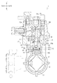
以下では、燃料噴射ポンプ1の全体的な構成について、図1を参照して説明する。なお、本明細書では、カム軸12の軸線方向を前後方向として規定するとともに、カム13が配置される側を後方と規定して、説明を行う。
<First embodiment>
Below, the whole structure of the fuel injection pump 1 is demonstrated with reference to FIG. In the present specification, the axial direction of the cam shaft 12 is defined as the front-rear direction, and the side on which the cam 13 is disposed is defined as the rear.

燃料噴射ポンプ1は、エンジンの燃料噴射装置に具備される装置であり、燃料タンク内の燃料油を燃料噴射ノズルに圧送するものである。また、燃料噴射ポンプ1は、下部ハウジング10と上部ハウジング30とを上下に組み付けて構成される。前記下部ハウジング10の下部には、カム室11が形成される。前記上部ハウジング30は下部ハウジング10の上に固定される。前記下部ハウジング10と、上部ハウジング30の下面と、によって取り囲まれた空間は、プランジャ室31を構成している。   The fuel injection pump 1 is a device provided in a fuel injection device of an engine, and pumps fuel oil in a fuel tank to a fuel injection nozzle. The fuel injection pump 1 is configured by vertically assembling a lower housing 10 and an upper housing 30. A cam chamber 11 is formed in the lower portion of the lower housing 10. The upper housing 30 is fixed on the lower housing 10. A space surrounded by the lower housing 10 and the lower surface of the upper housing 30 constitutes a plunger chamber 31.

前記下部ハウジング10には、カム軸12、カム13、及びタペット40等が組み込まれる。   The lower housing 10 incorporates a cam shaft 12, a cam 13, a tappet 40, and the like.

前記カム軸12は、その軸線方向が前後方向に平行となるように配置された状態で、下部ハウジング10に回転可能に支持される。カム軸12は、エンジンのクランク軸の回転により、歯車等を介して回転駆動される。前記カム13は、カム室11に収容され、前記カム軸12の後部に固定(嵌設)される。前記カム13は、カム軸12と一体化して回転することにより、カム軸12の回転力を昇降運動に変換してタペット40に伝達する。   The cam shaft 12 is rotatably supported by the lower housing 10 in a state in which the cam shaft 12 is arranged so that its axial direction is parallel to the front-rear direction. The camshaft 12 is rotationally driven via a gear or the like by the rotation of the crankshaft of the engine. The cam 13 is accommodated in the cam chamber 11 and fixed (fitted) to the rear portion of the cam shaft 12. The cam 13 rotates integrally with the cam shaft 12, thereby converting the rotational force of the cam shaft 12 into a lifting motion and transmitting it to the tappet 40.

前記タペット40は、下端部が閉塞された概ね円筒形状の部材であり、前記下部ハウジング10に形成されたタペット孔10aに嵌装される。該タペット孔10aは、前記カム室11とプランジャ室31とを上下方向に連通するように形成された孔であり、その外径の寸法はタペット40の外径の寸法よりも僅かに大きい。前記タペット40は、タペット孔10aに嵌装されることにより、その軸線方向がカム軸12と垂直な方向(上下方向)となる状態で、カム軸12の上方に配置される。   The tappet 40 is a substantially cylindrical member whose lower end is closed, and is fitted into a tappet hole 10 a formed in the lower housing 10. The tappet hole 10 a is a hole formed so that the cam chamber 11 and the plunger chamber 31 communicate with each other in the vertical direction. The outer diameter of the tappet hole 10 a is slightly larger than the outer diameter of the tappet 40. When the tappet 40 is fitted into the tappet hole 10a, the tappet 40 is disposed above the cam shaft 12 so that the axial direction of the tappet 40 is perpendicular to the cam shaft 12 (vertical direction).

前記タペット40は、図1及び図2に示すように、タペット構造体41、ローラ42、及び軸部材43により構成される。前記タペット構造体41は、カップ状に形成された底部41aと、該底部41aの外周から上方に突出した円周壁部41bと、を有する。前記ローラ42は、円柱形状の部材であり、軸部材43を中心として回転可能にタペット構造体41の底部41aに支持される。前記軸部材43は、底部41aに前後方向に平行に架け渡されるとともに、その前後両端部がタペット孔10aの外周面に形成されたガイド溝(不図示)に収容される。前記タペット構造体41は、軸部材43がガイド溝内を上下方向にスライドすることにより、タペット孔10aの内周面に沿って軸線方向にスライド可能である。換言すれば、前記タペット40は、タペット孔10a内を昇降可能であり、前記ローラ42は、タペット40がタペット孔10a内を昇降運動するとき、常にカム13の外周面に当接している。   As shown in FIGS. 1 and 2, the tappet 40 includes a tappet structure 41, a roller 42, and a shaft member 43. The tappet structure 41 includes a bottom portion 41a formed in a cup shape, and a circumferential wall portion 41b protruding upward from the outer periphery of the bottom portion 41a. The roller 42 is a cylindrical member, and is supported on the bottom 41 a of the tappet structure 41 so as to be rotatable about the shaft member 43. The shaft member 43 spans the bottom portion 41a in parallel in the front-rear direction, and both front and rear end portions are accommodated in guide grooves (not shown) formed on the outer peripheral surface of the tappet hole 10a. The tappet structure 41 is slidable in the axial direction along the inner peripheral surface of the tappet hole 10a when the shaft member 43 slides up and down in the guide groove. In other words, the tappet 40 can move up and down in the tappet hole 10a, and the roller 42 is always in contact with the outer peripheral surface of the cam 13 when the tappet 40 moves up and down in the tappet hole 10a.

前記上部ハウジング30には、プランジャバレル32、プランジャ33、下部バネ受け34、上部バネ受け35、及びプランジャバネ36等が組み込まれる。   In the upper housing 30, a plunger barrel 32, a plunger 33, a lower spring receiver 34, an upper spring receiver 35, a plunger spring 36, and the like are incorporated.

前記プランジャバレル32は、中央部に円柱形状の空洞が上下方向に形成された円筒形状の部材である。前記プランジャバレル32は、その軸線方向が上下方向に平行となる状態で上部ハウジング30に固定(嵌設)される。前記プランジャ33は、概ね円柱形状の部材であり、プランジャバレル32に嵌装される。前記プランジャ33は、プランジャバレル32の内周面に沿って軸線方向にスライド可能である。換言すれば、前記プランジャ33は、プランジャバレル32の円柱形状の空洞内を昇降可能である。前記プランジャ33の上面とプランジャバレル32の円柱形状の空洞の内周面と、によって取り囲まれた空間は、燃料油を加圧するための加圧室32aを構成している。   The plunger barrel 32 is a cylindrical member having a columnar cavity formed in the vertical direction at the center. The plunger barrel 32 is fixed (fitted) to the upper housing 30 with its axial direction being parallel to the vertical direction. The plunger 33 is a substantially cylindrical member and is fitted to the plunger barrel 32. The plunger 33 is slidable in the axial direction along the inner peripheral surface of the plunger barrel 32. In other words, the plunger 33 can move up and down in the cylindrical cavity of the plunger barrel 32. A space surrounded by the upper surface of the plunger 33 and the inner peripheral surface of the cylindrical hollow of the plunger barrel 32 constitutes a pressurizing chamber 32a for pressurizing the fuel oil.

前記下部バネ受け34は、プランジャ33の下端部に相対回転可能に係合された状態で、タペット40の内側(底部41aの上)に収容される。前記下部バネ受け34には、シール部材であるOリング60が取り付けられる。該Oリング60は、タペット40と下部バネ受け34の間に位置するように設けられる。前記上部バネ受け35は、前記プランジャ33に嵌装された状態で、プランジャバレル32の下端部に相対回転可能に支持される。   The lower spring receiver 34 is accommodated inside the tappet 40 (on the bottom 41a) in a state of being engaged with the lower end of the plunger 33 so as to be relatively rotatable. An O-ring 60 that is a seal member is attached to the lower spring receiver 34. The O-ring 60 is provided so as to be positioned between the tappet 40 and the lower spring receiver 34. The upper spring receiver 35 is supported by the lower end portion of the plunger barrel 32 so as to be relatively rotatable while being fitted to the plunger 33.

前記プランジャバネ36は、プランジャ33の下端部に嵌装される。前記プランジャバネ36は、プランジャ33の外周を取り囲むとともに、下部バネ受け34と上部バネ受け35との間に介在するように取り付けられる。前記プランジャ33は、プランジャバネ36から受ける付勢力により、下降方向に付勢されている。このような構成により、プランジャ33の下端部は、下部バネ受け34及び調整シム47を介してタペット40の底部41aに押し付けられている。   The plunger spring 36 is fitted to the lower end portion of the plunger 33. The plunger spring 36 is attached so as to surround the outer periphery of the plunger 33 and to be interposed between the lower spring receiver 34 and the upper spring receiver 35. The plunger 33 is urged in the downward direction by the urging force received from the plunger spring 36. With such a configuration, the lower end of the plunger 33 is pressed against the bottom 41 a of the tappet 40 via the lower spring receiver 34 and the adjustment shim 47.

前記タペット40の内側(底部41aの上)には、調整シム47が収容され、該調整シム47の上には、下部バネ受け34が載せられる。調整シム47の寸法及び個数等を適宜変更することにより、プランジャ33の上下方向の位置が精度良く調整される。なお、図1に示す燃料噴射ポンプ1においては、前記下部バネ受け34は調整シム47を介してタペット40の底部41aの上に載せられるものとしたが、本発明はこれに限るものではない。例えば、この構成に代えて、下部バネ受け34がタペット40の底部41aの上に直接的に載せられる構成としても良い。   An adjustment shim 47 is accommodated inside the tappet 40 (on the bottom 41 a), and a lower spring receiver 34 is placed on the adjustment shim 47. By appropriately changing the dimensions and number of the adjustment shims 47, the vertical position of the plunger 33 is adjusted with high accuracy. In the fuel injection pump 1 shown in FIG. 1, the lower spring receiver 34 is placed on the bottom 41 a of the tappet 40 via the adjustment shim 47, but the present invention is not limited to this. For example, instead of this configuration, the lower spring receiver 34 may be placed directly on the bottom 41 a of the tappet 40.

燃料噴射ポンプ1の左側部には、図1に示すように、フィードポンプ7が具備される。フィードポンプ7は加圧室32aに燃料を供給するためのポンプであり、エンジンのクランク軸の回転により駆動される。燃料タンクの燃料油は、フィードポンプ7、及び、上部ハウジング30に形成された燃料ギャラリ30aを経由して、プランジャバレル32の加圧室32a内に供給される。   As shown in FIG. 1, a feed pump 7 is provided on the left side of the fuel injection pump 1. The feed pump 7 is a pump for supplying fuel to the pressurizing chamber 32a, and is driven by the rotation of the crankshaft of the engine. The fuel oil in the fuel tank is supplied into the pressurizing chamber 32 a of the plunger barrel 32 via the feed pump 7 and the fuel gallery 30 a formed in the upper housing 30.

燃料噴射ポンプ1は、以下のように作動する。すなわち、カム軸12が回転すると、タペット40がタペット孔10a内を昇降運動し、プランジャ33がプランジャバレル32の円柱形状の空洞内を昇降運動する。プランジャ33が下降方向に移動すると、加圧室32aの体積が増大し、加圧室32a内の圧力が低下する。プランジャ33が燃料ギャラリ30aと加圧室32aとが連通する状態となるまで下降したとき、燃料タンクの燃料油がフィードポンプ7より加圧室32a内に供給される。一方、プランジャ33が上昇方向に移動して、燃料ギャラリ30aと加圧室32aとが連通しない状態になると、加圧室32aの体積が減少し、加圧室32a内の圧力が上昇する。こうして加圧された加圧室32a内の燃料油は、分配機構(不図示)を介して各気筒の燃料噴射ノズルから噴射される。   The fuel injection pump 1 operates as follows. That is, when the cam shaft 12 rotates, the tappet 40 moves up and down in the tappet hole 10a, and the plunger 33 moves up and down in the cylindrical cavity of the plunger barrel 32. When the plunger 33 moves in the downward direction, the volume of the pressurizing chamber 32a increases and the pressure in the pressurizing chamber 32a decreases. When the plunger 33 is lowered until the fuel gallery 30a and the pressurizing chamber 32a communicate with each other, the fuel oil in the fuel tank is supplied from the feed pump 7 into the pressurizing chamber 32a. On the other hand, when the plunger 33 moves in the upward direction and the fuel gallery 30a and the pressurizing chamber 32a do not communicate with each other, the volume of the pressurizing chamber 32a decreases and the pressure in the pressurizing chamber 32a increases. The fuel oil in the pressurizing chamber 32a thus pressurized is injected from the fuel injection nozzle of each cylinder through a distribution mechanism (not shown).

燃料噴射ポンプ1のカム室11内には、潤滑油が供給されている。潤滑油は、前記カム13とローラ42との当接部、及び、前記タペット構造体41の円周壁部41bとタペット孔10aとの当接面(スライド面)等において、部材間のすべり運動により生じる摩擦力や摩耗を低減する役割を果たす。   Lubricating oil is supplied into the cam chamber 11 of the fuel injection pump 1. Lubricating oil is generated by sliding motion between members at the contact portion between the cam 13 and the roller 42 and the contact surface (slide surface) between the circumferential wall portion 41b of the tappet structure 41 and the tappet hole 10a. It plays a role in reducing the frictional force and wear that occurs.

以下では、下部バネ受け34の構成について、図2を参照して詳細に説明する。下部バネ受け34は、「下部バネ受け」の実施の一形態に相当する。下部バネ受け34は、円盤形状の円盤部34aと、突出部34bと、を合わせた形状を有する。   Below, the structure of the lower spring receiver 34 is demonstrated in detail with reference to FIG. The lower spring receiver 34 corresponds to an embodiment of a “lower spring receiver”. The lower spring support 34 has a shape in which a disk-shaped disk part 34a and a protruding part 34b are combined.

下部バネ受け34の前記突出部34bは、円盤部34aの上部から延出されるとともに、平面視略円形状の板面34fを形成している。該板面34fの中央部には、平面視略U字形状の係合溝34cが形成される。下部バネ受け34の前記板面34fの外縁部から係合溝34cに、前記プランジャ33の下端部を挿入することにより、前記プランジャ33を前記係合溝34cに係合することが可能である。プランジャ33は、昇降運動に伴って、下部バネ受け34に対して僅かに上下方向に移動可能である。具体的には、プランジャ33は、下端部33aの下端面が下部バネ受け34の円盤部34aに当接する位置から、その下端部33aの上端面が板面34fに当接する位置までの範囲内において、上下方向に若干量だけ移動可能である。   The projecting portion 34b of the lower spring support 34 extends from the upper portion of the disk portion 34a and forms a plate surface 34f having a substantially circular shape in plan view. An engagement groove 34c having a substantially U shape in plan view is formed in the center of the plate surface 34f. The plunger 33 can be engaged with the engagement groove 34c by inserting the lower end portion of the plunger 33 from the outer edge portion of the plate surface 34f of the lower spring receiver 34 into the engagement groove 34c. The plunger 33 can move slightly in the vertical direction with respect to the lower spring receiver 34 as the elevator moves up and down. Specifically, the plunger 33 is within a range from a position where the lower end surface of the lower end portion 33a contacts the disk portion 34a of the lower spring receiver 34 to a position where the upper end surface of the lower end portion 33a contacts the plate surface 34f. It is possible to move by a slight amount in the vertical direction.

下部バネ受け34の前記円盤部34aの下端部には、下部バネ受け34の半径方向外側に向かって突出したバネ受け部34dが形成される。該バネ受け部34dは環形状の部分であり、前記円盤部34aの中央部に対して外下方に一様に凹んだ形状を有する(段差が形成されている)。平面視においてバネ受け部34dにより取り囲まれている部分(円盤部34aの中央部)を、プランジャバネ36の下端部に嵌装することにより、バネ受け部34dがプランジャバネ36の下端部に取り付けられる。   At the lower end of the disk portion 34 a of the lower spring receiver 34, a spring receiver 34 d that protrudes outward in the radial direction of the lower spring receiver 34 is formed. The spring receiving portion 34d is an annular portion, and has a shape that is uniformly recessed outward and downward with respect to the central portion of the disk portion 34a (a step is formed). By fitting a portion surrounded by the spring receiving portion 34 d in the plan view (the center portion of the disk portion 34 a) to the lower end portion of the plunger spring 36, the spring receiving portion 34 d is attached to the lower end portion of the plunger spring 36. .

下部バネ受け34の前記係合溝34eは、バネ受け部34d(下部バネ受け34)の外周面に沿って環形状に形成された溝である。係合溝34eは、下部バネ受け34の最大径の側面に形成される。係合溝34eは、バネ受け部34dの外周面の全周にわたって一様に形成される。   The engaging groove 34e of the lower spring receiver 34 is a groove formed in an annular shape along the outer peripheral surface of the spring receiver 34d (lower spring receiver 34). The engaging groove 34e is formed on the side surface of the lower spring receiver 34 having the maximum diameter. The engagement groove 34e is formed uniformly over the entire circumference of the outer peripheral surface of the spring receiving portion 34d.

以下では、Oリング60の構成について、図2を参照して詳細に説明する。Oリング60は、「シール部材」の実施の一形態に相当する。前記Oリング60は、下部バネ受け34がタペット構造体41の円周壁部41bに密着した状態を保持するための部材であり、タペット40の円周壁部41bの内周面と、下部バネ受け34のバネ受け部34dの外周面と、の間に設けられる。   Hereinafter, the configuration of the O-ring 60 will be described in detail with reference to FIG. The O-ring 60 corresponds to an embodiment of a “seal member”. The O-ring 60 is a member for maintaining the state in which the lower spring receiver 34 is in close contact with the circumferential wall portion 41 b of the tappet structure 41, and the inner peripheral surface of the circumferential wall portion 41 b of the tappet 40 and the lower spring receiver 34. And the outer peripheral surface of the spring receiving portion 34d.

前記Oリング60は、例えばフッ素ゴム等の弾性変形可能な材料により構成される。Oリング60は下部バネ受け34の係合溝34eに係合される。Oリング60の断面の直径は、係合溝34eの深さよりも大きい寸法となるように設定される。したがって、弾性変形していない状態におけるOリング60は、バネ受け部34dの外周面から外部に向かって(下部バネ受け34の半径方向外側に向かって)突出している。   The O-ring 60 is made of an elastically deformable material such as fluorine rubber. The O-ring 60 is engaged with the engagement groove 34 e of the lower spring receiver 34. The diameter of the cross section of the O-ring 60 is set to be larger than the depth of the engagement groove 34e. Accordingly, the O-ring 60 in a state where it is not elastically deformed protrudes outward (outward in the radial direction of the lower spring receiver 34) from the outer peripheral surface of the spring receiver 34d.

このような構成のOリング60は、バネ受け部34dの係合溝34eに係合された状態で、タペット40の内側に収容される。このとき、Oリング60は、弾性変形した状態でタペット40の円周壁部41bの内周面に当接する。より詳細には、Oリング60の外周部は、弾性力(Oリング60が弾性変形した形状から元の形状に戻ろうとする力)により、円周壁部41bの内周面に押し付けられている。したがって、下部バネ受け34はタペット構造体41の底部41aから離間(遊離)し難い。また、下部バネ受け34とタペット40との密着性を確保することができる。   The O-ring 60 having such a configuration is accommodated inside the tappet 40 while being engaged with the engagement groove 34e of the spring receiving portion 34d. At this time, the O-ring 60 comes into contact with the inner peripheral surface of the circumferential wall portion 41b of the tappet 40 in an elastically deformed state. More specifically, the outer peripheral portion of the O-ring 60 is pressed against the inner peripheral surface of the circumferential wall portion 41b by an elastic force (a force for returning from the shape in which the O-ring 60 is elastically deformed to the original shape). Accordingly, the lower spring receiver 34 is unlikely to be separated (released) from the bottom 41 a of the tappet structure 41. Further, the adhesion between the lower spring receiver 34 and the tappet 40 can be ensured.

一般的な従来の燃料噴射ポンプにおいては、プランジャ及びプランジャバレルの間の摺動抵抗に起因して、プランジャ及び下部バネ受けの下降速度が、タペットの下降速度よりも遅くなる場合があった。とりわけ、プランジャが上死点の直後において下降方向へ移動する状況下では、プランジャ及び下部バネ受けは前記の摺動抵抗により下降方向への移動が妨げられる一方、タペットは重力により下降方向に速やかに移動する。このため、プランジャ及び下部バネ受けの下降速度が、タペットの下降速度に追従できなくなり、下部バネ受けがタペットから一時的に遊離する虞があった。   In a general conventional fuel injection pump, due to sliding resistance between the plunger and the plunger barrel, the lowering speed of the plunger and the lower spring receiver may be slower than the lowering speed of the tappet. In particular, in the situation where the plunger moves in the downward direction immediately after top dead center, the plunger and the lower spring receiver are prevented from moving in the downward direction by the sliding resistance, while the tappet is promptly moved in the downward direction by gravity. Moving. For this reason, the lowering speed of the plunger and the lower spring receiver cannot follow the lowering speed of the tappet, and there is a possibility that the lower spring receiver is temporarily released from the tappet.

この点、本実施形態に係る燃料噴射ポンプ1においては、下部バネ受け34及びタペット構造体41の間はOリング60によりシールされているから、下部バネ受け34がタペット構造体41の底部41aから離間(遊離)し難い。また、下部バネ受け34とタペット40との密着性を確保することができる。よって、タペット40(タペット構造体41の円周壁部41b)と、下部バネ受け34と、の隙間から潤滑油がプランジャ室31内に浸入し、ひいては燃料油に混入する、という事態の発生を抑制することができる。結果として、潤滑油由来の金属成分が燃料噴射ノズル先端に付着して噴霧を悪化させたり、排気色が悪化したり、燃料が黒色化したり、エンジンの燃費が低下したりすることを防止することができる。   In this respect, in the fuel injection pump 1 according to the present embodiment, the space between the lower spring receiver 34 and the tappet structure 41 is sealed by the O-ring 60, so that the lower spring receiver 34 is separated from the bottom 41 a of the tappet structure 41. It is difficult to separate (free). Further, the adhesion between the lower spring receiver 34 and the tappet 40 can be ensured. Therefore, the occurrence of a situation in which the lubricating oil enters the plunger chamber 31 from the gap between the tappet 40 (circumferential wall portion 41b of the tappet structure 41) and the lower spring receiver 34, and eventually enters the fuel oil is suppressed. can do. As a result, the metal component derived from the lubricating oil adheres to the tip of the fuel injection nozzle and deteriorates the spray, the exhaust color is deteriorated, the fuel is blackened, and the fuel consumption of the engine is prevented. Can do.

なお、燃料噴射ポンプ1においては、Oリング60と下部バネ受け34とを合わせたものをアッセンブリー(集合体)としてプランジャ33の下端部に取り付けたり、取り外したりすることが可能である。換言すれば、下部バネ受け34をプランジャ33の下端部から取り外すだけで、該プランジャ33と一緒にOリング60も取り外すことが可能である。したがって、シール部材(本実施形態ではOリング60)を新品に交換することが容易となり、ひいてはメンテナンス性が向上する。   In the fuel injection pump 1, a combination of the O-ring 60 and the lower spring receiver 34 can be attached to or removed from the lower end portion of the plunger 33 as an assembly. In other words, the O-ring 60 can be removed together with the plunger 33 simply by removing the lower spring receiver 34 from the lower end of the plunger 33. Therefore, it becomes easy to replace the seal member (O-ring 60 in the present embodiment) with a new one, and as a result, maintainability is improved.

<第二実施形態>
以下では、第二実施形態に係る燃料噴射ポンプ1の構成について、図3を参照して説明する。第二実施形態に係る燃料噴射ポンプ1は、(1)下部バネ受け34に代えて下部バネ受け134を具備し、(2)Oリング60に代えてOリング70を具備する点で、第一実施形態に係る燃料噴射ポンプ1と相違する。
<Second embodiment>
Below, the structure of the fuel injection pump 1 which concerns on 2nd embodiment is demonstrated with reference to FIG. The fuel injection pump 1 according to the second embodiment includes (1) a lower spring receiver 134 instead of the lower spring receiver 34, and (2) an O ring 70 instead of the O ring 60. This is different from the fuel injection pump 1 according to the embodiment.

下部バネ受け134は、「下部バネ受け」の実施の一形態である。下部バネ受け134は、下部バネ受け34と同様に、円盤形状の円盤部134aと、該円盤部134aから上方に突出する突出部134bと、を合わせた形状を有する。   The lower spring receiver 134 is an embodiment of a “lower spring receiver”. Similarly to the lower spring receiver 34, the lower spring receiver 134 has a shape in which a disk-shaped disk portion 134a and a protruding portion 134b protruding upward from the disk portion 134a are combined.

下部バネ受け134の前記突出部134bは、円盤部134aの上部から延出されるとともに、平面視略円字形状の板面134fを形成している。該板面134fの中央部には、平面視略U字形状の係合溝134cが形成される。該係合溝134cにはプランジャ33の下端部が係合される。   The protruding portion 134b of the lower spring support 134 extends from the upper portion of the disk portion 134a and forms a plate surface 134f having a substantially circular shape in plan view. An engagement groove 134c having a substantially U shape in plan view is formed in the center of the plate surface 134f. The lower end portion of the plunger 33 is engaged with the engagement groove 134c.

下部バネ受け134の前記円盤部134aの下端部には、下部バネ受け134の半径方向外側に向かって突出したバネ受け部134dが形成される。該バネ受け部134dは平面視環形状の部分であり、円盤部134aの中央部に対して下方に一様に凹んだ形状を有する(段差が形成されている)。平面視においてバネ受け部134dにより取り囲まれている部分を、プランジャバネ36の下端部に嵌装することにより、バネ受け部134dがプランジャバネ36の下端部に取り付けられる。   At the lower end of the disk portion 134 a of the lower spring receiver 134, a spring receiver 134 d that protrudes outward in the radial direction of the lower spring receiver 134 is formed. The spring receiving portion 134d is a ring-shaped portion in plan view, and has a shape that is uniformly depressed downward (a step is formed) with respect to the central portion of the disc portion 134a. By fitting a portion surrounded by the spring receiving portion 134 d in a plan view to the lower end portion of the plunger spring 36, the spring receiving portion 134 d is attached to the lower end portion of the plunger spring 36.

下部バネ受け134の前記係合溝134eは、バネ受け部134d(下部バネ受け134)の底面に形成された溝である。該係合溝134eは、バネ受け部134dの底面の外周の縁に沿って環形状に形成される。本実施形態の係合溝134eは、断面視略凹状の形状を有する溝であり、バネ受け部134dの底面の全周にわたって一様に形成される。本実施形態の係合溝134eは、バネ受け部134dの底面の外周と同心円上に形成される。   The engagement groove 134e of the lower spring receiver 134 is a groove formed on the bottom surface of the spring receiver 134d (lower spring receiver 134). The engaging groove 134e is formed in a ring shape along the outer peripheral edge of the bottom surface of the spring receiving portion 134d. The engagement groove 134e of the present embodiment is a groove having a substantially concave shape in cross section, and is formed uniformly over the entire circumference of the bottom surface of the spring receiving portion 134d. The engagement groove 134e of the present embodiment is formed concentrically with the outer periphery of the bottom surface of the spring receiving portion 134d.

以下では、Oリング70の構成について、図3を参照して詳細に説明する。Oリング70は、「シール部材」の実施の一形態に相当する。前記Oリング70は、下部バネ受け134がタペット構造体41の底部41a(厳密には調整シム47の上面)に密着した状態を保持するための部材であり、タペット40の底部41aの上面(調整シム47の上面)と、下部バネ受け134のバネ受け部134dの底面(下面)と、の間に設けられる。   Hereinafter, the configuration of the O-ring 70 will be described in detail with reference to FIG. The O-ring 70 corresponds to an embodiment of a “seal member”. The O-ring 70 is a member for holding the lower spring support 134 in close contact with the bottom 41a of the tappet structure 41 (strictly, the upper surface of the adjustment shim 47), and the upper surface of the bottom 41a of the tappet 40 (adjustment). It is provided between the upper surface of the shim 47 and the bottom surface (lower surface) of the spring receiving portion 134d of the lower spring receiver 134.

前記Oリング70は、例えばシリコーンゴム等の弾性変形可能な材料により構成される。Oリング70は下部バネ受け134の係合溝134eに係合される。Oリング70の断面の直径は、係合溝134eの深さよりも大きい寸法となるように設定される。したがって、弾性変形していない状態におけるOリング70は、バネ受け部134dの底面から下方に向かって突出している。   The O-ring 70 is made of an elastically deformable material such as silicone rubber. The O-ring 70 is engaged with the engagement groove 134e of the lower spring receiver 134. The diameter of the cross section of the O-ring 70 is set to be larger than the depth of the engagement groove 134e. Therefore, the O-ring 70 in a state where it is not elastically deformed protrudes downward from the bottom surface of the spring receiving portion 134d.

このような構成のOリング70は、バネ受け部134dの係合溝134eに係合された状態で、タペット40の内側(調整シム47の上)に収容される。このとき、Oリング70は、弾性変形した状態で調整シム47の上面に当接する。より詳細には、Oリング70は、バネ受け部134dによって上方から押されて調整シム47に押し付けられることにより、全周にわたって圧縮された状態で調整シム47の上面に当接する。したがって、プランジャ33及びプランジャバレル32の間に大きな摺動抵抗が生じても、下部バネ受け134と調整シム47(タペット40の底部41a)との間がOリング70により埋められた状態が保持される。すなわち、弾性変形によりOリング70の厚みが増減されるので、下部バネ受け134がタペット構造体41の底部41a(厳密には調整シム47の上面)から離間(遊離)し難い。また、下部バネ受け134とタペット40との密着性を確保することができる。よって、タペット40(タペット構造体41の底部41a)と、下部バネ受け134と、の隙間から潤滑油がプランジャ室31内に浸入し、ひいては燃料油に混入する、という事態の発生を抑制することができる。   The O-ring 70 having such a configuration is accommodated inside the tappet 40 (on the adjustment shim 47) in a state of being engaged with the engagement groove 134e of the spring receiving portion 134d. At this time, the O-ring 70 comes into contact with the upper surface of the adjustment shim 47 in an elastically deformed state. More specifically, the O-ring 70 is pressed from above by the spring receiving portion 134d and pressed against the adjustment shim 47, thereby contacting the upper surface of the adjustment shim 47 in a compressed state over the entire circumference. Therefore, even if a large sliding resistance is generated between the plunger 33 and the plunger barrel 32, the state in which the space between the lower spring receiver 134 and the adjustment shim 47 (the bottom 41a of the tappet 40) is filled with the O-ring 70 is maintained. The That is, since the thickness of the O-ring 70 is increased or decreased by elastic deformation, the lower spring receiver 134 is unlikely to be separated (released) from the bottom 41a of the tappet structure 41 (strictly, the upper surface of the adjustment shim 47). In addition, adhesion between the lower spring support 134 and the tappet 40 can be ensured. Therefore, the occurrence of a situation in which the lubricating oil enters the plunger chamber 31 through the gap between the tappet 40 (the bottom 41a of the tappet structure 41) and the lower spring receiver 134 and eventually enters the fuel oil is suppressed. Can do.

<第三実施形態>
以下では、第三実施形態に係る燃料噴射ポンプ1の構成について、図4を参照して説明する。第三実施形態に係る燃料噴射ポンプ1は、(1)下部バネ受け34に代えて下部バネ受け334を具備し、(2)Oリング60に代えてシールシート80を具備する点で、第一実施形態に係る燃料噴射ポンプ1と相違する。
<Third embodiment>
Below, the structure of the fuel injection pump 1 which concerns on 3rd embodiment is demonstrated with reference to FIG. The fuel injection pump 1 according to the third embodiment is (1) provided with a lower spring receiver 334 instead of the lower spring receiver 34, and (2) provided with a seal sheet 80 instead of the O-ring 60. This is different from the fuel injection pump 1 according to the embodiment.

下部バネ受け334は、「下部バネ受け」の実施の一形態である。下部バネ受け334は、下部バネ受け34と同様に、円盤形状の円盤部334aと、該円盤部334aから上方に突出する突出部334bと、を合わせた形状を有する。前記円盤部334aには、第一実施形態における下部バネ受け34の係合溝34eに相当する溝が形成されていない。   The lower spring receiver 334 is an embodiment of a “lower spring receiver”. Similar to the lower spring receiver 34, the lower spring receiver 334 has a shape in which a disk-shaped disk portion 334a and a protruding portion 334b protruding upward from the disk portion 334a are combined. The disk portion 334a is not formed with a groove corresponding to the engaging groove 34e of the lower spring receiver 34 in the first embodiment.

シールシート80は、「シール部材」の実施の一形態である。該シールシート80は、弾性変形可能な材料により構成されるシート状の部材であり、下部バネ受け334におけるバネ受け部334dの外周面の全周にわたって貼り付けられている。   The seal sheet 80 is an embodiment of a “seal member”. The seal sheet 80 is a sheet-like member made of an elastically deformable material, and is attached to the entire periphery of the outer peripheral surface of the spring receiving portion 334d in the lower spring receiver 334.

このような構成のシールシート80は、バネ受け部334dの外周面に貼り付けられた状態で、タペット40の内側に収容される。このとき、シールシート80は、弾性変形した状態でタペット40の円周壁部41bの内周面に当接する。より詳細には、シールシート80の外周部は、弾性力により円周壁部41bの内周面に押し付けられている。したがって、プランジャ33及びプランジャバレル32の間に大きな摺動抵抗が生じても、下部バネ受け334がタペット構造体41の底部41aから離間(遊離)し難い。また、下部バネ受け334とタペット40との密着性を確保することができる。   The seal sheet 80 having such a configuration is accommodated inside the tappet 40 in a state where the seal sheet 80 is attached to the outer peripheral surface of the spring receiving portion 334d. At this time, the seal sheet 80 comes into contact with the inner peripheral surface of the circumferential wall portion 41b of the tappet 40 in an elastically deformed state. More specifically, the outer peripheral portion of the seal sheet 80 is pressed against the inner peripheral surface of the circumferential wall portion 41b by an elastic force. Therefore, even if a large sliding resistance is generated between the plunger 33 and the plunger barrel 32, the lower spring receiver 334 is difficult to separate (release) from the bottom 41 a of the tappet structure 41. In addition, adhesion between the lower spring receiver 334 and the tappet 40 can be ensured.

<第四実施形態>
以下では、第四実施形態に係る燃料噴射ポンプ1の構成について、図5を参照して説明する。第四実施形態に係る燃料噴射ポンプ1は、シールシート80に代えてシールシート90を具備する点で、第三実施形態に係る燃料噴射ポンプ1と相違する。
<Fourth embodiment>
Below, the structure of the fuel injection pump 1 which concerns on 4th embodiment is demonstrated with reference to FIG. The fuel injection pump 1 according to the fourth embodiment is different from the fuel injection pump 1 according to the third embodiment in that a seal sheet 90 is provided instead of the seal sheet 80.

シールシート90は、「シール部材」の実施の一形態である。該シールシート90は、弾性変形可能な材料により構成される環形状または円板状のシート状の部材であり、バネ受け部334dにおける底面の外周の縁に沿って、底面の全周にわたって貼り付けられている。   The seal sheet 90 is an embodiment of a “seal member”. The seal sheet 90 is a ring-shaped or disk-shaped sheet member made of an elastically deformable material, and is attached to the entire periphery of the bottom surface along the edge of the outer periphery of the bottom surface of the spring receiving portion 334d. It has been.

このような構成のシールシート90は、バネ受け部334dの底面に貼り付けられた状態で、タペット40の内側に収容される。このとき、シールシート90は、弾性変形した状態で調整シム47の上面に当接する。より詳細には、シールシート90は、バネ受け部334dによって上方から押されて調整シム47に押し付けられることにより、全周にわたって圧縮された状態で調整シム47の上面に当接する。したがって、プランジャ33及びプランジャバレル32の間に大きな摺動抵抗が生じても、下部バネ受け334と調整シム47(タペット40の底部41a)との間がシールシート90により埋められた状態が保持される。すなわち、弾性変形によりシールシート90の厚みが増減されるので、下部バネ受け334がタペット構造体41の底部41a(厳密には調整シム47の上面)から離間(遊離)し難い。また、下部バネ受け334とタペット40との密着性を確保することができる。   The seal sheet 90 having such a configuration is accommodated inside the tappet 40 in a state of being attached to the bottom surface of the spring receiving portion 334d. At this time, the seal sheet 90 comes into contact with the upper surface of the adjustment shim 47 in an elastically deformed state. More specifically, the seal sheet 90 is pressed from above by the spring receiving portion 334d and pressed against the adjustment shim 47, so that the seal sheet 90 comes into contact with the upper surface of the adjustment shim 47 in a compressed state. Therefore, even if a large sliding resistance is generated between the plunger 33 and the plunger barrel 32, the state in which the space between the lower spring receiver 334 and the adjustment shim 47 (the bottom 41a of the tappet 40) is filled with the seal sheet 90 is maintained. The That is, since the thickness of the seal sheet 90 is increased or decreased by elastic deformation, the lower spring receiver 334 is unlikely to be separated (released) from the bottom 41a of the tappet structure 41 (strictly, the upper surface of the adjustment shim 47). In addition, adhesion between the lower spring receiver 334 and the tappet 40 can be ensured.

<第五実施形態>
以下では、第五実施形態に係る燃料噴射ポンプ1の構成について、図6を参照して説明する。第五実施形態に係る燃料噴射ポンプ1は、シールシート80に代えてシールシート100を具備する点で、第三実施形態に係る燃料噴射ポンプ1と相違する。
<Fifth embodiment>
Below, the structure of the fuel injection pump 1 which concerns on 5th embodiment is demonstrated with reference to FIG. The fuel injection pump 1 according to the fifth embodiment is different from the fuel injection pump 1 according to the third embodiment in that a seal sheet 100 is provided instead of the seal sheet 80.

シールシート100は、「シール部材」の実施の一形態である。該シールシート100は、弾性変形可能な材料により構成される環形状のシート状の部材であり、その断面は概ねL字形状を有する。該シールシート100は、バネ受け部334dにおける底面の外周の縁(角部)を覆うように、底面の全周にわたって貼り付けられている。   The seal sheet 100 is an embodiment of a “seal member”. The seal sheet 100 is a ring-shaped sheet-like member made of an elastically deformable material, and has a substantially L-shaped cross section. The seal sheet 100 is affixed over the entire periphery of the bottom surface so as to cover the edge (corner portion) of the bottom surface of the spring receiving portion 334d.

このような構成のシールシート100は、バネ受け部334dの外周面及び底面に貼り付けられた状態で、タペット40の内側に収容される。このとき、シールシート100は、弾性変形した状態で、タペット40の円周壁部41bの内周面、及び、調整シム47の上面に当接する。より詳細には、シールシート100は、弾性力により円周壁部41bの内周面に押し付けられるとともに、全周にわたって圧縮された状態で調整シム47の上面に押し付けられる。したがって、下部バネ受け334がタペット構造体41の底部41aから離間(遊離)し難い。また、下部バネ受け334とタペット40との密着性を確保することができる。とりわけ、本実施形態のシールシート100においては、下部バネ受け334とタペット40の円周壁部41bとの間、及び、下部バネ受け334とタペット構造体41の底部41aとの間、の両方の密着性を確保することができる。よって、燃料噴射ポンプ1内の燃料油に潤滑油が混入することを、より確実に防止できる。   The seal sheet 100 having such a configuration is accommodated inside the tappet 40 in a state of being attached to the outer peripheral surface and the bottom surface of the spring receiving portion 334d. At this time, the seal sheet 100 comes into contact with the inner peripheral surface of the circumferential wall portion 41 b of the tappet 40 and the upper surface of the adjustment shim 47 in an elastically deformed state. More specifically, the seal sheet 100 is pressed against the inner peripheral surface of the circumferential wall portion 41b by an elastic force, and is pressed against the upper surface of the adjustment shim 47 while being compressed over the entire circumference. Therefore, the lower spring receiver 334 is unlikely to be separated (released) from the bottom 41 a of the tappet structure 41. In addition, adhesion between the lower spring receiver 334 and the tappet 40 can be ensured. In particular, in the seal sheet 100 of the present embodiment, both the lower spring receiver 334 and the circumferential wall portion 41b of the tappet 40 and the lower spring receiver 334 and the bottom portion 41a of the tappet structure 41 are in close contact with each other. Sex can be secured. Therefore, it can prevent more reliably that lubricating oil mixes in the fuel oil in the fuel injection pump 1. FIG.

1 燃料噴射ポンプ
32 プランジャバレル
33 プランジャ
34 下部バネ受け
34e 係合溝
35 上部バネ受け
36 プランジャバネ
40 タペット
60 Oリング(シール部材)
70 Oリング(シール部材)
134e 係合溝
DESCRIPTION OF SYMBOLS 1 Fuel injection pump 32 Plunger barrel 33 Plunger 34 Lower spring receiver 34e Engaging groove 35 Upper spring receiver 36 Plunger spring 40 Tappet 60 O-ring (seal member)
70 O-ring (seal member)
134e engagement groove

Claims (3)

プランジャとタペットとの間に、プランジャバネを介装し、該プランジャバネは、上部バネ受けと下部バネ受けとの間に介装される燃料噴射ポンプにおいて、
前記下部バネ受けはプランジャの下端部に相対回転可能に係合された状態で、タペットの内側の底部上に収容され、
該下部バネ受けの下端部には半径方向外側に向かって突出したバネ受け部を形成し、該バネ受け部上に、前記プランジャバネの下端部を係止し、
前記タペットとバネ受け部との間に、弾性変形可能な材料により構成されるシール部材を介装した
ことを特徴とする燃料噴射ポンプ。
In the fuel injection pump, a plunger spring is interposed between the plunger and the tappet, and the plunger spring is interposed between the upper spring receiver and the lower spring receiver.
The lower spring receiver is accommodated on the inner bottom portion of the tappet in a state of being relatively rotatably engaged with the lower end portion of the plunger,
A spring receiving portion protruding radially outward is formed at a lower end portion of the lower spring receiving portion, and a lower end portion of the plunger spring is locked on the spring receiving portion,
A fuel injection pump, wherein a seal member made of an elastically deformable material is interposed between the tappet and the spring receiving portion .
プランジャとタペットとの間に、プランジャバネを介装し、該プランジャバネは、上部バネ受けと下部バネ受けとの間に介装される燃料噴射ポンプにおいて、
前記下部バネ受けはプランジャの下端部に相対回転可能に係合された状態で、タペットの内側の底部上に収容され、
該下部バネ受けの下端部には半径方向外側に向かって突出したバネ受け部を形成し、該バネ受け部上に、前記プランジャバネの下端部を係止し、
前記タペットとバネ受け部の外周面との間に、弾性変形可能な材料により構成されたシール部材を介装した
ことを特徴とする燃料噴射ポンプ。
In the fuel injection pump, a plunger spring is interposed between the plunger and the tappet, and the plunger spring is interposed between the upper spring receiver and the lower spring receiver.
The lower spring receiver is accommodated on the inner bottom portion of the tappet in a state of being relatively rotatably engaged with the lower end portion of the plunger,
A spring receiving portion protruding radially outward is formed at a lower end portion of the lower spring receiving portion, and a lower end portion of the plunger spring is locked on the spring receiving portion,
A fuel injection pump, wherein a seal member made of an elastically deformable material is interposed between the tappet and the outer peripheral surface of the spring receiving portion .
プランジャとタペットとの間に、プランジャバネを介装し、該プランジャバネは、上部バネ受けと下部バネ受けとの間に介装される燃料噴射ポンプにおいて、
前記下部バネ受けはプランジャの下端部に相対回転可能に係合された状態で、タペットの内側の底部上に収容され、
該下部バネ受けの下端部には半径方向外側に向かって突出したバネ受け部を形成し、該バネ受け部上に、前記プランジャバネの下端部を係止し、
前記タペットとバネ受け部の下面との間に、弾性変形可能な材料により構成されたシール部材を介装した
ことを特徴とする燃料噴射ポンプ。
In the fuel injection pump, a plunger spring is interposed between the plunger and the tappet, and the plunger spring is interposed between the upper spring receiver and the lower spring receiver.
The lower spring receiver is accommodated on the inner bottom portion of the tappet in a state of being relatively rotatably engaged with the lower end portion of the plunger,
A spring receiving portion protruding radially outward is formed at a lower end portion of the lower spring receiving portion, and a lower end portion of the plunger spring is locked on the spring receiving portion,
A fuel injection pump, wherein a seal member made of an elastically deformable material is interposed between the tappet and the lower surface of the spring receiving portion .
JP2010090216A 2010-04-09 2010-04-09 Fuel injection pump Expired - Fee Related JP5592143B2 (en)

Priority Applications (1)

Application Number Priority Date Filing Date Title
JP2010090216A JP5592143B2 (en) 2010-04-09 2010-04-09 Fuel injection pump

Applications Claiming Priority (1)

Application Number Priority Date Filing Date Title
JP2010090216A JP5592143B2 (en) 2010-04-09 2010-04-09 Fuel injection pump

Publications (2)

Publication Number Publication Date
JP2011220223A JP2011220223A (en) 2011-11-04
JP5592143B2 true JP5592143B2 (en) 2014-09-17

Family

ID=45037507

Family Applications (1)

Application Number Title Priority Date Filing Date
JP2010090216A Expired - Fee Related JP5592143B2 (en) 2010-04-09 2010-04-09 Fuel injection pump

Country Status (1)

Country Link
JP (1) JP5592143B2 (en)

Families Citing this family (4)

* Cited by examiner, † Cited by third party
Publication number Priority date Publication date Assignee Title
EP2660459B1 (en) * 2012-05-03 2016-04-06 Delphi International Operations Luxembourg S.à r.l. Load reduction
WO2016109676A1 (en) 2014-12-30 2016-07-07 Graco Minnesota Inc. Self-aligning mounting and retention system
BR102018003284B1 (en) 2017-02-21 2021-07-20 Graco Minnesota Inc. PISTON ROD FOR A PUMP, PUMP, SPRAYER, AND METHOD FOR REPLACING A WEAR GLOVE
AU2021248838A1 (en) 2020-03-31 2022-10-13 Graco Minnesota Inc. Pump drive system

Family Cites Families (3)

* Cited by examiner, † Cited by third party
Publication number Priority date Publication date Assignee Title
JP4210025B2 (en) * 2000-08-23 2009-01-14 ヤンマー株式会社 Fuel injection pump
JP4081429B2 (en) * 2003-11-14 2008-04-23 ヤンマー株式会社 Fuel injection pump
JP4081431B2 (en) * 2003-12-11 2008-04-23 ヤンマー株式会社 Fuel injection pump

Also Published As

Publication number Publication date
JP2011220223A (en) 2011-11-04

Similar Documents

Publication Publication Date Title
JP5592143B2 (en) Fuel injection pump
JP2022009152A (en) Piston pump
JP6533290B2 (en) Pump unit for supplying fuel, preferably diesel fuel, to an internal combustion engine
JP4649500B2 (en) Sealing device
JP2593352B2 (en) Valve train for internal combustion engine
GB2449282B (en) High speed flywheel containment
JP2023080365A (en) sealing device
US10273920B2 (en) Single piston pump with reduced piston side loads
KR20180072576A (en) Piston pump, in particular high-pressure fuel pump for an internal combustion engine
US10030715B2 (en) Bearing, clutch bearing device and motor vehicle equipped with such a clutch bearing device
EP2405153B1 (en) Clutch release bearing device
CN110939738B (en) Quick-release end face sealing device
JP6914417B2 (en) Piston pumps, especially high pressure fuel pumps for internal combustion engines
JP2017207089A (en) Seal
US20110220070A1 (en) Structural assembly comprising a pump piston and a tappet
JP5973243B2 (en) Rocker arm with built-in lash adjuster
JP2013100910A (en) Hydraulic clutch release device
JP2010084891A (en) Hydraulic clutch release device
JP5592148B2 (en) Fuel injection pump
KR102200570B1 (en) Clutch piston in automatic transmission clutch unit
CN219281805U (en) Wear-resistant hydraulic tappet
JP2012013213A (en) Mechanical seal
CN110030052B (en) Hydraulic camshaft adjuster
CN209875762U (en) Bearing assembly
WO2021220576A1 (en) Valve stem seal

Legal Events

Date Code Title Description
A621 Written request for application examination

Free format text: JAPANESE INTERMEDIATE CODE: A621

Effective date: 20130226

A977 Report on retrieval

Free format text: JAPANESE INTERMEDIATE CODE: A971007

Effective date: 20131213

A131 Notification of reasons for refusal

Free format text: JAPANESE INTERMEDIATE CODE: A131

Effective date: 20131217

A521 Written amendment

Free format text: JAPANESE INTERMEDIATE CODE: A523

Effective date: 20140214

TRDD Decision of grant or rejection written
A01 Written decision to grant a patent or to grant a registration (utility model)

Free format text: JAPANESE INTERMEDIATE CODE: A01

Effective date: 20140722

A61 First payment of annual fees (during grant procedure)

Free format text: JAPANESE INTERMEDIATE CODE: A61

Effective date: 20140731

R150 Certificate of patent or registration of utility model

Ref document number: 5592143

Country of ref document: JP

Free format text: JAPANESE INTERMEDIATE CODE: R150

S531 Written request for registration of change of domicile

Free format text: JAPANESE INTERMEDIATE CODE: R313531

R350 Written notification of registration of transfer

Free format text: JAPANESE INTERMEDIATE CODE: R350

LAPS Cancellation because of no payment of annual fees