JP5590650B2 - Friction welding joint structure of two two-dimensional parts - Google Patents
Friction welding joint structure of two two-dimensional parts Download PDFInfo
- Publication number
- JP5590650B2 JP5590650B2 JP2009536624A JP2009536624A JP5590650B2 JP 5590650 B2 JP5590650 B2 JP 5590650B2 JP 2009536624 A JP2009536624 A JP 2009536624A JP 2009536624 A JP2009536624 A JP 2009536624A JP 5590650 B2 JP5590650 B2 JP 5590650B2
- Authority
- JP
- Japan
- Prior art keywords
- connection body
- joint structure
- friction
- friction welding
- collar
- Prior art date
- Legal status (The legal status is an assumption and is not a legal conclusion. Google has not performed a legal analysis and makes no representation as to the accuracy of the status listed.)
- Active
Links
Images


Classifications
-
- B—PERFORMING OPERATIONS; TRANSPORTING
- B23—MACHINE TOOLS; METAL-WORKING NOT OTHERWISE PROVIDED FOR
- B23K—SOLDERING OR UNSOLDERING; WELDING; CLADDING OR PLATING BY SOLDERING OR WELDING; CUTTING BY APPLYING HEAT LOCALLY, e.g. FLAME CUTTING; WORKING BY LASER BEAM
- B23K20/00—Non-electric welding by applying impact or other pressure, with or without the application of heat, e.g. cladding or plating
- B23K20/12—Non-electric welding by applying impact or other pressure, with or without the application of heat, e.g. cladding or plating the heat being generated by friction; Friction welding
- B23K20/129—Non-electric welding by applying impact or other pressure, with or without the application of heat, e.g. cladding or plating the heat being generated by friction; Friction welding specially adapted for particular articles or workpieces
-
- B—PERFORMING OPERATIONS; TRANSPORTING
- B23—MACHINE TOOLS; METAL-WORKING NOT OTHERWISE PROVIDED FOR
- B23K—SOLDERING OR UNSOLDERING; WELDING; CLADDING OR PLATING BY SOLDERING OR WELDING; CUTTING BY APPLYING HEAT LOCALLY, e.g. FLAME CUTTING; WORKING BY LASER BEAM
- B23K20/00—Non-electric welding by applying impact or other pressure, with or without the application of heat, e.g. cladding or plating
- B23K20/002—Non-electric welding by applying impact or other pressure, with or without the application of heat, e.g. cladding or plating specially adapted for particular articles or work
-
- B—PERFORMING OPERATIONS; TRANSPORTING
- B23—MACHINE TOOLS; METAL-WORKING NOT OTHERWISE PROVIDED FOR
- B23K—SOLDERING OR UNSOLDERING; WELDING; CLADDING OR PLATING BY SOLDERING OR WELDING; CUTTING BY APPLYING HEAT LOCALLY, e.g. FLAME CUTTING; WORKING BY LASER BEAM
- B23K20/00—Non-electric welding by applying impact or other pressure, with or without the application of heat, e.g. cladding or plating
- B23K20/12—Non-electric welding by applying impact or other pressure, with or without the application of heat, e.g. cladding or plating the heat being generated by friction; Friction welding
- B23K20/122—Non-electric welding by applying impact or other pressure, with or without the application of heat, e.g. cladding or plating the heat being generated by friction; Friction welding using a non-consumable tool, e.g. friction stir welding
- B23K20/1245—Non-electric welding by applying impact or other pressure, with or without the application of heat, e.g. cladding or plating the heat being generated by friction; Friction welding using a non-consumable tool, e.g. friction stir welding characterised by the apparatus
- B23K20/1255—Tools therefor, e.g. characterised by the shape of the probe
-
- B—PERFORMING OPERATIONS; TRANSPORTING
- B23—MACHINE TOOLS; METAL-WORKING NOT OTHERWISE PROVIDED FOR
- B23K—SOLDERING OR UNSOLDERING; WELDING; CLADDING OR PLATING BY SOLDERING OR WELDING; CUTTING BY APPLYING HEAT LOCALLY, e.g. FLAME CUTTING; WORKING BY LASER BEAM
- B23K20/00—Non-electric welding by applying impact or other pressure, with or without the application of heat, e.g. cladding or plating
- B23K20/12—Non-electric welding by applying impact or other pressure, with or without the application of heat, e.g. cladding or plating the heat being generated by friction; Friction welding
- B23K20/129—Non-electric welding by applying impact or other pressure, with or without the application of heat, e.g. cladding or plating the heat being generated by friction; Friction welding specially adapted for particular articles or workpieces
- B23K20/1295—Welding studs
-
- B—PERFORMING OPERATIONS; TRANSPORTING
- B23—MACHINE TOOLS; METAL-WORKING NOT OTHERWISE PROVIDED FOR
- B23K—SOLDERING OR UNSOLDERING; WELDING; CLADDING OR PLATING BY SOLDERING OR WELDING; CUTTING BY APPLYING HEAT LOCALLY, e.g. FLAME CUTTING; WORKING BY LASER BEAM
- B23K2103/00—Materials to be soldered, welded or cut
- B23K2103/18—Dissimilar materials
-
- B—PERFORMING OPERATIONS; TRANSPORTING
- B23—MACHINE TOOLS; METAL-WORKING NOT OTHERWISE PROVIDED FOR
- B23K—SOLDERING OR UNSOLDERING; WELDING; CLADDING OR PLATING BY SOLDERING OR WELDING; CUTTING BY APPLYING HEAT LOCALLY, e.g. FLAME CUTTING; WORKING BY LASER BEAM
- B23K2103/00—Materials to be soldered, welded or cut
- B23K2103/30—Organic material
- B23K2103/42—Plastics
-
- Y—GENERAL TAGGING OF NEW TECHNOLOGICAL DEVELOPMENTS; GENERAL TAGGING OF CROSS-SECTIONAL TECHNOLOGIES SPANNING OVER SEVERAL SECTIONS OF THE IPC; TECHNICAL SUBJECTS COVERED BY FORMER USPC CROSS-REFERENCE ART COLLECTIONS [XRACs] AND DIGESTS
- Y10—TECHNICAL SUBJECTS COVERED BY FORMER USPC
- Y10T—TECHNICAL SUBJECTS COVERED BY FORMER US CLASSIFICATION
- Y10T403/00—Joints and connections
- Y10T403/47—Molded joint
- Y10T403/477—Fusion bond, e.g., weld, etc.
Description
この発明はお互いの頂部に位置する複数の二次元部品を含む摩擦溶接接合に関し、複数の二次元部品は、カラーによって上側の部品に位置する接続本体によって結合される。 The invention relates to a friction weld joint comprising a plurality of two-dimensional parts located on top of each other, the plurality of two-dimensional parts being joined by a connection body located on the upper part by means of a collar.
このタイプの摩擦溶接接合はDE19620814A1から公知である。互いの頂部に位置し、アルミニウムやアルミ合金のような同じ種類の材料で構成されている2つの二次元部品が、この公知の摩擦溶接接合によって結合される。平坦な円錐、またはのこぎり状溝を有するように設計された接続本体の閉じた前部が上側の部品に置かれて、圧力の下の回転によって後者に差し込まれるという事実によって、このために使用される摩擦溶接接合は生産される。上側の部品は可塑化され、そして、得られた溶融状態の材料は2つの部品をお互いに接続する。 This type of friction weld joint is known from DE 19620814 A1. Two known two-dimensional parts located on top of each other and made of the same type of material, such as aluminum or aluminum alloy, are joined by this known friction weld joint. Used for this by the fact that the closed front part of the connecting body designed to have a flat cone or saw-like groove is placed on the upper part and plugged into the latter by rotation under pressure Friction weld joints are produced. The upper part is plasticized and the resulting molten material connects the two parts together.
この方法によると、上側の部品の材料は、上側の部品に差し込まれている接続本体の全断面にわたって溶かすか、または機械加工しなければならないが、切りくずをどのように除去するのかは不明である。上側の部品の関連領域が溶かされるなら、これはかなりのエネルギー量を必要とする。したがって、お互いの頂部に位置する2つの部品の間で摩擦溶接接合を生成するための公報から公知の方法は、かなりの技術的問題を伴う。 According to this method, the material of the upper part must be melted or machined over the entire cross-section of the connecting body that is plugged into the upper part, but it is unclear how the chips are removed. is there. This requires a significant amount of energy if the relevant area of the upper part is melted. The method known from the publication for producing a friction weld joint between two parts located on top of each other is therefore associated with considerable technical problems.
お互いの頂部に位置する2個の薄板の間で摩擦溶接接合を生産するための同様の方法はPCT公報WO98/04381に開示されている。この方法で、丸いスタンプは放射状に一部を切取った平坦な前部を有する摩擦要素として使用される。これは、回転および圧力によって上側の薄板を通して押され、それによって、後者は溶ける。次に、スタンプは下側の薄板に比較的短い長さだけ入り込み、そして、また、下側の薄板は溶ける。その結果、円柱状にある程度スタンプを囲む溶融帯が形成され、この方法で、2個の薄板が結合される。そして、スタンプは溶融帯から引っ込められる。 A similar method for producing a friction weld joint between two sheets located on top of each other is disclosed in PCT publication WO 98/04381. In this way, the round stamp is used as a friction element with a flat front part cut out radially. This is pushed through the upper lamina by rotation and pressure, whereby the latter melts. The stamp then enters the lower sheet for a relatively short length, and the lower sheet also melts. As a result, a molten zone surrounding the stamp to some extent is formed in a cylindrical shape, and two thin plates are joined in this manner. The stamp is then withdrawn from the melt zone.
この方法においても、下側の薄板からの溶融材料、特に、上部薄板からの比較的大量の溶融材料がどこに流れるのか不明である。とにかく、これは公報からはわからない。 In this method as well, it is unclear where the molten material from the lower sheet, in particular where a relatively large amount of molten material from the upper sheet flows. Anyway, this is not known from the gazette.
お互いの頂部に位置する2つの二次元部品のための摩擦溶接接合を設計するための既存の必要性を考慮すると、接続本体がお互いの頂部に位置する2つの部品の上側の部品に差し込まれるとき、それによって溶けた材料は妨害を避けるために何らかの方法で収容されなければならないという知識は、明らかに、EP1230062B1で説明された方法になる。これは、原則として、WO98/04381で説明されるように行われ、これによって、間隔をあけてスタンプを取り巻き、上側部分を押すスリーブはスリーブの内表面とスタンプとの間に付加的なスペースを生成し、そこへ、この材料が溶けた時上下の部品からの材料が流れる。それからスタンプはこの材料をある程度この空洞に押し、そこから、それは押し出され、それによって、上下の部品のプランジャー浸透部に対応する比較的大きな領域を液体で満たす。この液体が上下の部品の間の接続を形成する。 Given the existing need to design a friction weld joint for two two-dimensional parts located on top of each other, when the connecting body is plugged into the upper part of the two parts located on top of each other The knowledge that the material melted thereby has to be accommodated in some way to avoid interference is clearly the method described in EP1230062B1. This is in principle carried out as described in WO 98/04381, whereby the sleeve that surrounds the stamp at a distance and pushes the upper part provides an additional space between the inner surface of the sleeve and the stamp. The material from the upper and lower parts flows when this material melts. The stamp then pushes this material to some extent into this cavity, from where it is pushed, thereby filling a relatively large area corresponding to the plunger penetration of the upper and lower parts. This liquid forms a connection between the upper and lower parts.
これは技術的な観点から行いにくい方法である。これは、特に多量の熱が必要であり、単に上側または下側の部品の材料を可塑化するだけでは溶融状態の材料が流れることを引き起こすためには不十分であるためである。代わりに、スリーブとスタンプの間の環状隙間に材料が流れるようにし、そして、それが置き換えられたスペースに流れ返すのを可能にするために、比較的高い粘着性を有するようにこの材料を溶かさなければならない。 This is a difficult method from a technical point of view. This is because a particularly large amount of heat is required and simply plasticizing the material of the upper or lower part is not sufficient to cause the molten material to flow. Instead, the material is melted to have a relatively high tack to allow the material to flow through the annular gap between the sleeve and the stamp and to allow it to flow back into the displaced space. There must be.
この発明の目的は、お互いの頂部に位置する複数の二次元部品の摩擦溶接接合を生成することである。ここでは、集中した回転摩擦溶接領域が、接続本体周りの狭い限られた空間である接触領域に生成され、必ずお互いの頂部に位置する二次元部品から置き換えられる材料が、互いの頂部に位置する複数の部品間の摩擦溶接接合および接続本体が十分組み立てられたとき、材料が妨げにならないように集められるようにしてもよい。 An object of the present invention is to produce a friction weld joint of a plurality of two-dimensional parts located on top of each other. Here, a concentrated rotational friction welding area is created in the contact area, which is a narrow limited space around the connecting body, and the material that must be replaced from the two-dimensional parts located on top of each other is located on top of each other When the friction weld joint between the parts and the connection body are fully assembled, the material may be collected so that it does not interfere.
この発明によると、この目的は接続本体がチューブ要素として設計され、上側の部品は回転と圧力によって前部の環状の切断端縁を有する接続本体によって差し込まれることによって達成される。ここで、接続本体は、その前部で上側の部品を切断し、上側部品の切断した材料をその空洞部に収容した後、下側の部品と共に、接続本体の回転および圧力によって生成された摩擦溶接領域を形成する。 According to the invention, this object is achieved by the connecting body being designed as a tube element and the upper part being inserted by means of rotation and pressure with a connecting body having a front annular cutting edge. Here, the connection body cuts the upper part at the front part, and after the cut material of the upper part is accommodated in the cavity, the friction generated by the rotation and pressure of the connection body together with the lower part. Form a weld zone.
接続本体をチューブ片として設計したため、接続本体の空洞のスペースは、最終的にチューブ状の接続本体の前部の領域に必要な摩擦溶接ゾーンを生成するために、後者が圧力と回転の下に置かれたとき接続本体から除去されるべき二次元部品からの材料を収容するためのスペースをもたらす。接続本体をチューブとして設計したため、このチューブ片の前部を環状の切断端縁として利用することができ、この環状切断端縁は、二次元部品と接触している、ほんの比較的狭い領域のみで二次元部品から、比較的わずかな量だけを取り除いて可塑化する必要がある。このことは、材料を加熱するための必要なエネルギーを提供するのに重要である。接続本体に取り付けられたカラーが、二次元部品を結合するのに利用されて、この接続本体は、カラーによって上側の部品に位置し、下側の部品に後者を押しつける。この下側の部品は、摩擦溶接領域によって接続本体の前部と上側部品の下側の縁の両方に接続され、それによって、お互いの頂部に位置する2つの部品間に永久的な丈夫な接続が達成される。これは、好ましくは、互いの頂部に位置する2つの部品に関するが、多数の二次元部品がこのように互いに接続されてもよい。 Since the connection body is designed as a tube piece, the cavity space of the connection body will eventually create the necessary friction welding zone in the area of the front of the tube-like connection body, the latter under pressure and rotation When placed, it provides space for accommodating material from the two-dimensional part to be removed from the connection body. Since the connecting body is designed as a tube, the front of the tube piece can be used as an annular cutting edge, which is only in a relatively small area in contact with the two-dimensional part. Only a relatively small amount needs to be removed from the two-dimensional part and plasticized. This is important in providing the necessary energy to heat the material. A collar attached to the connection body is used to join the two-dimensional parts, the connection body being positioned on the upper part by the collar and pressing the latter against the lower part. This lower part is connected to both the front of the connection body and the lower edge of the upper part by means of a friction welding area, so that a permanent and robust connection between the two parts located on top of each other Is achieved. This preferably relates to two parts located on top of each other, but a number of two-dimensional parts may thus be connected to each other.
接続本体の相応しい設計は、それが空洞のボルトとして設計されているときである。しかしながら、接続本体をナットとして設計することも可能である。 A suitable design for the connecting body is when it is designed as a hollow bolt. However, it is also possible to design the connection body as a nut.
有利には、上側の部品は軽金属で作られる。しかしながら、また、プラスチックで上側の部品を設計するのも可能である。 Advantageously, the upper part is made of light metal. However, it is also possible to design the upper part with plastic.
同様の選択は下側の部品にも存在する。例えば、それは、金属かプラスチックのどちらで作られてもよい。 Similar choices exist for the lower part. For example, it may be made of either metal or plastic.
また、接続本体に使用される材料のために様々なオプションが存在す。有利な実施の形態は、接続本体を金属から生産することである。しかしながら、また、プラスチックで接続本体を設計することも可能である。 There are also various options for the materials used in the connection body. An advantageous embodiment is to produce the connection body from metal. However, it is also possible to design the connection body with plastic.
回転と圧力によって互いの頂部に位置する二次元部品に差し込まれる接続本体の環状の切断端縁を、環状の切断端縁に関して好ましく設計するには、後者には、チューブとして設計された接続本体の上にシャープな外側端縁が設けられる。チューブの前は漏斗の形に空洞のスペースと一体化し、それによって、二次元部品からの溶融状態の材料を容易に収容する。 In order to preferably design an annular cutting edge of a connection body that is inserted into a two-dimensional part located on top of each other by rotation and pressure, with respect to the annular cutting edge, the latter includes a connection body designed as a tube. A sharp outer edge is provided on the top. The front of the tube is integrated with the hollow space in the form of a funnel, thereby easily accommodating the molten material from the two-dimensional part.
外側の縁は、ナイフの刃のような閉じた円周を有してもよいが、外側の端縁に歯を設けてもよい。 The outer edge may have a closed circumference, such as a knife blade, but may be provided with teeth on the outer edge.
上側の部品の向きに所望の連続したプリテンションを有するカラーを提供するために、上側の部品を押し付けるばね要素をカラーと上側の部品の間に適切に設ける。バネ要素に所望のプリテンションを与えるために、回転式の摩擦溶接領域を形成した後に、停止しているときに、カラーは上側の部品に対して押し付けられる。これは、接続本体が停止しているときに、カラーに作用する軸方向圧縮力によって適切に行なわれる。 In order to provide a collar having the desired continuous pretension in the orientation of the upper part, a spring element that presses the upper part is suitably provided between the collar and the upper part. The collar is pressed against the upper part when it is stopped after forming the rotary friction weld zone to provide the spring element with the desired pretension. This is suitably done by the axial compressive force acting on the collar when the connecting body is at rest.
チューブの周りで二次元部品からの溶融状態の材料が途中でフランジの向きに外部まで流れ出るのを防ぐために、カラーには上側の部品に対向する側面に環状のリッジ(突起部)が適切に設けられる。この環状のリッジは半径方向における外側へのシールとしてある程度作用する。 To prevent the molten material from the two-dimensional part from flowing around the tube to the outside in the direction of the flange, the collar is appropriately provided with an annular ridge (protrusion) on the side facing the upper part It is done. This annular ridge acts to some extent as a radially outward seal.
結果として生じる高い表面圧力のため、環状の尾根は上側の部品に押し込まれる。 Due to the resulting high surface pressure, the annular ridge is pushed into the upper part.
本発明の模範的実施の形態は図面に例示される。 Exemplary embodiments of the invention are illustrated in the drawings.
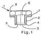
図1は、チューブ状の空洞のボルトとして設計された接続本体1を示している。このボルトは、環状の切断端縁4が設けられた前部3を有するチューブ片2を含む。チューブ片2の材料は環状の切断端縁4から始まり、漏斗5の形状で接続本体1の空洞のスペース6と一体化する。
FIG. 1 shows a connection body 1 designed as a tubular hollow bolt. This bolt comprises a
接続本体1は前部3の反対側にカラー7を有し、カラーは部分的断面として示され、前部3から遠く離れた側で六角形8と一体化される。六角形8は回転機械の任意のチャックに収容されるために使用される。
The connecting body 1 has a
図2は図1による、接続本体を含む摩擦溶接接合を示す。この図は互いの頂部に位置する2つの二次元部品、すなわち、上側の部品9と下側の部品10とを示し、これらは、互の上にぴったりと位置する。チューブ片2は上側の部品9に接続本体1の回転と圧力によって下側の部品10に達するまで差し込まれる。これによって、移動された材料11は上側の部品9から、チューブ部分2の空洞のスペース6に押しだされる。最終的な摩擦溶接において、移動された材料11は、このように安全にチューブ片2に収容されて、そこから出ることができない。これは、摩擦溶接領域12がチューブ片2の前部に形成されて、しっかりと本体1を接続する部品10を保持するためである。この摩擦溶接領域12は少なくとも表面で移動された材料と一体化し、それによって、それを所定の位置で保持する。接続本体1の反対側では、接続本体1は上側の部品9にカラー7を押し付け、上側部品9はそれによって、カラー7と下側の部品10の間である程度固定される。また、2つの部品9と10の代わりに、3以上の二次元部品に接続本体を設けてもよい。
FIG. 2 shows a friction weld joint including a connecting body according to FIG. This figure shows two two-dimensional parts located on top of each other, an upper part 9 and a
図1に従った接続本体の代わりに、図3に示される接続本体の使用も可能である。これは、空洞のボルト13によって形成されたものである。任意のナットを介した空洞のボルト13に更なる部品を取り付けることを可能にするネジ14は、空洞のボルト13に切られる。空洞のボルト13は貫通孔15を有し、貫通孔15は前部3の領域(図1の前部3に対応)において空洞のスペース6のように設計され、ねじ14の領域に狭い貫通孔15を有し、この狭い貫通孔15は前部3から離れた空洞の本体13の側の六角ソケット16で終了する。六角ソケット16は回転機械のツールを収容するのに使用され、それによって、接続本体13が互いの頂部に位置する二次元部品に対して回転され押し付けられる。接続本体の機能のさらなる詳細については、図1と図2のための説明を参照すること。
Instead of the connection body according to FIG. 1, it is also possible to use the connection body shown in FIG. This is formed by the
図4は接続本体の更なる変形を示している。そこでは、接続本体はナット17である。ナット17は、チューブ状のデザインである。これは、上側の部品から切り取られた材料を収容するための空洞の貫通スペース18を有することを意味する。ナットについて一般的であるように、接続本体17には確実に駆動ツールに取付けらるように六角形が設けられている。
FIG. 4 shows a further variant of the connection body. There, the connection body is a
再度特定の接続本体の前部3の機能に関して図1と2を参照する。ここでは、接続本体1,13にその前部3に刃が設けられ、刃は前部3の外側端に沿って環状に設けられ、内部に向けて漏斗5を形成している。これによって、上側の二次元部品9から切り取られたどの材料が、空洞のスペース6に搬送されてもよい。
Reference is again made to FIGS. 1 and 2 regarding the function of the
図4に従ったナットとしての接続本体17の実施の形態では、外側の縁21に沿って歯22を前部20に設ける。これによって、上側の部品におかれたとき、フライスカッターのように上側の部品からの材料を歯が粉砕し、その材料は上記したように、関連する接続本体の空洞のスペース18または6に搬送される。
In the embodiment of the connecting
図5は図1に従う接続本体1を示している。図5によると、皿バネ23が追加されている。皿バネ23はカラー7の下でチューブ片2に押されて、図2に示す活性状態で特定のバネ上部品9を押すために使用され、それによって、たとえ回転による摩擦溶接領域12(図2を参照)が上側の部品9に対して接続本体1を安定して引き込まなくても、上側の部品9が張力を与えられた皿バネ23によって、カラー7を介して接続本体1を押す。
FIG. 5 shows the connection body 1 according to FIG. According to FIG. 5, a
図6は接続本体のデザインの変更を示している。この場合、上側の部品9に面する側のカラー7の領域において、接続本体には環状のリッジ24が設けられる。環状のリッジ24は上側の部品9の表面に位置したとき、カラー7の外側端縁に沿って位置し、シールを形成し、それによって、摩擦溶接領域の生成によって液化された材料は、カラー7の向きでチューブ片2の外部で両方の部品9と10から押され、そこで、環状のリッジ24によって外へ漏れるのが防がれる。
FIG. 6 shows a change in the design of the connection body. In this case, an
さらに、図6によると、接続本体1は環状のリッジ24によって上記したように安定したシールを形成するために上側の部品9に押しつけられるという事実を参照されたい。この押圧動作は接続本体の回転の終了時に別の工程として適切に行われる。すなわち、接続本体が停止していると、回転工具から接続本体1に圧力を付与することによって、接続本体1が上側の部品に押し込まれる。
Furthermore, according to FIG. 6, reference is made to the fact that the connecting body 1 is pressed against the upper part 9 by means of an
Claims (14)
環状の切断端縁(4)がチューブ(2)の鋭い外側の縁によって形成され、そこから、チューブ片(2)の前部(3)が漏斗の形の空洞のスペース(6)に接続され、
チューブ片(2)の空洞スペース(6)は、カラー(7)の最下端面を越えて延在することを特徴とする、摩擦溶接接合構造。 A friction welding joint structure for a part (9, 10) having a plurality of two-dimensional planes including a lower part and an upper part located above the lower part, wherein the plurality of parts are connected by a connection body (1, 17). The connecting body is located above the upper part (9) by the collar (7), cuts the upper part (9) by its front part (3), and its hollow space (6) After accommodating the cutting material on the upper part (9), the connection body (1, 17) is a tube piece (2), and the connection body (1, 17) having a front annular cutting edge (4). ) Penetrates the upper part (9) by rotation and pressure and together with the lower part (1) forms a friction welding region (12) generated by the rotation and pressure of the connection body (1, 17),
An annular cutting edge (4) is formed by the sharp outer edge of the tube (2), from which the front (3) of the tube piece (2) is connected to a funnel-shaped cavity space (6). ,
Friction weld joint structure, characterized in that the hollow space (6) of the tube piece (2) extends beyond the lowermost end surface of the collar (7) .
環状の切断端縁(4)がチューブ(2)の鋭い外側の縁によって形成され、そこから、チューブ片(2)の前部(3)が漏斗の形の空洞のスペース(6)に接続され、
接続本体(1)が空洞のボルトとして設計されていることを特徴とする、摩擦溶接接合構造。 A friction welding joint structure for a part (9, 10) having a plurality of two-dimensional planes including a lower part and an upper part located above the lower part, wherein the plurality of parts are connected by a connection body (1, 17). The connecting body is located above the upper part (9) by the collar (7), cuts the upper part (9) by its front part (3), and its hollow space (6) After accommodating the cutting material on the upper part (9), the connection body (1, 17) is a tube piece (2), and the connection body (1, 17) having a front annular cutting edge (4). ) Penetrates the upper part (9) by rotation and pressure and together with the lower part (1) forms a friction welding region (12) generated by the rotation and pressure of the connection body (1, 17),
An annular cutting edge (4) is formed by the sharp outer edge of the tube (2), from which the front (3) of the tube piece (2) is connected to a funnel-shaped cavity space (6). ,
Friction weld joint structure, characterized in that the connection body (1) is designed as a hollow bolt .
環状の切断端縁(4)がチューブ(2)の鋭い外側の縁によって形成され、そこから、チューブ片(2)の前部(3)が漏斗の形の空洞のスペース(6)に接続され、
接続本体(17)がナットとして設計されていることを特徴とする、摩擦溶接接合構造。 A friction welding joint structure for a part (9, 10) having a plurality of two-dimensional planes including a lower part and an upper part located above the lower part, wherein the plurality of parts are connected by a connection body (1, 17). The connecting body is located above the upper part (9) by the collar (7), cuts the upper part (9) by its front part (3), and its hollow space (6) After accommodating the cutting material on the upper part (9), the connection body (1, 17) is a tube piece (2), and the connection body (1, 17) having a front annular cutting edge (4). ) Penetrates the upper part (9) by rotation and pressure and together with the lower part (1) forms a friction welding region (12) generated by the rotation and pressure of the connection body (1, 17),
An annular cutting edge (4) is formed by the sharp outer edge of the tube (2), from which the front (3) of the tube piece (2) is connected to a funnel-shaped cavity space (6). ,
Friction welding joint structure, characterized in that the connection body (17) is designed as a nut .
Applications Claiming Priority (3)
| Application Number | Priority Date | Filing Date | Title |
|---|---|---|---|
| DE102006053800A DE102006053800A1 (en) | 2006-11-15 | 2006-11-15 | Friction welding connection of two superimposed flat components |
| DE102006053800.5 | 2006-11-15 | ||
| PCT/EP2007/009366 WO2008058625A1 (en) | 2006-11-15 | 2007-10-29 | Friction welding joint of two two-dimensional components positioned on top of each other |
Publications (2)
| Publication Number | Publication Date |
|---|---|
| JP2010509072A JP2010509072A (en) | 2010-03-25 |
| JP5590650B2 true JP5590650B2 (en) | 2014-09-17 |
Family
ID=38989836
Family Applications (1)
| Application Number | Title | Priority Date | Filing Date |
|---|---|---|---|
| JP2009536624A Active JP5590650B2 (en) | 2006-11-15 | 2007-10-29 | Friction welding joint structure of two two-dimensional parts |
Country Status (8)
| Country | Link |
|---|---|
| US (1) | US8434962B2 (en) |
| EP (1) | EP2091685B1 (en) |
| JP (1) | JP5590650B2 (en) |
| KR (1) | KR20090089855A (en) |
| CN (1) | CN101557901B (en) |
| DE (1) | DE102006053800A1 (en) |
| ES (1) | ES2393629T3 (en) |
| WO (1) | WO2008058625A1 (en) |
Families Citing this family (24)
| Publication number | Priority date | Publication date | Assignee | Title |
|---|---|---|---|---|
| DE102007021891A1 (en) * | 2007-05-10 | 2008-11-13 | Ejot Gmbh & Co. Kg | Method for producing a friction-welded connection and design of the friction-welded connection |
| DE102008014599B4 (en) | 2008-03-17 | 2018-01-25 | Ejot Gmbh & Co. Kg | Chuck for holding fasteners for a friction weld |
| DE102008028687A1 (en) * | 2008-06-17 | 2009-12-24 | Ejot Gmbh & Co. Kg | Reibschweißverbindung of several superposed flat components |
| ES2383776T3 (en) * | 2009-12-03 | 2012-06-26 | Helmholtz-Zentrum Geesthacht Zentrum für Material- und Küstenforschung GmbH | Method for joining metal and plastic parts |
| DE102010017550A1 (en) * | 2010-06-23 | 2011-12-29 | Ejot Gmbh & Co. Kg | Connecting element for a friction-welded connection for connecting at least two plate-like components |
| JP5915042B2 (en) * | 2011-09-12 | 2016-05-11 | 株式会社ジェイテクト | Friction joint structure and pump device |
| US20140205369A1 (en) * | 2013-01-21 | 2014-07-24 | Magna Powertrain Ag & Co. Kg | Joint design welding dissimilar materials |
| KR101459614B1 (en) * | 2013-04-30 | 2014-11-07 | 주식회사 신영 | Welding method of vehicle-body mounting part |
| JP6484245B2 (en) * | 2013-12-23 | 2019-03-13 | 上海交通大学Shanghai Jiao Tong University | Friction welding structural member, cylinder head of water-cooled internal combustion engine, water-cooled internal combustion engine, and mechanical device equipped with water-cooled internal combustion engine |
| DE102015207052A1 (en) | 2015-04-17 | 2016-10-20 | Ejot Gmbh & Co. Kg | Connecting element for positive connection with at least one component |
| DE102015213633B3 (en) * | 2015-07-20 | 2016-11-03 | Volkswagen Aktiengesellschaft | Method for joining at least two components by means of friction spot welding and a friction element designed as a joining element and joining device |
| DE102016107961A1 (en) * | 2016-04-28 | 2017-11-02 | Ejot Gmbh & Co. Kg | Method and device for connecting two plate-like components |
| FR3065895B1 (en) * | 2017-05-04 | 2019-07-12 | Maxime Grojean | INSERT FOR ASSEMBLING A FIRST PART AND A SECOND PART BY RESISTOR ELECTRICAL WELDING, AND ASSEMBLY METHOD USING THE SAME |
| CN107471664A (en) * | 2017-06-30 | 2017-12-15 | 无锡市京锡冶金液压机电有限公司 | A kind of automatic rubber bulb-tubulating machine |
| DE102017116708B4 (en) * | 2017-07-24 | 2019-01-31 | Peter Martin Dufter | Method for producing a friction-welded joint |
| DE102017221378A1 (en) * | 2017-11-29 | 2019-05-29 | Zf Friedrichshafen Ag | Component assembly, axle housing, bolts and method for producing the component assembly |
| CN117733309A (en) | 2018-05-09 | 2024-03-22 | 杨百翰大学 | System and method for friction bit engagement |
| DE102018114982A1 (en) * | 2018-06-21 | 2019-12-24 | Ejot Gmbh & Co. Kg | Connecting element and component connection, and method for producing the same |
| JP2020015089A (en) * | 2018-07-27 | 2020-01-30 | 宏二 上谷 | Method of confining molten metal in rotary friction welding |
| DE102019104318C5 (en) | 2019-02-20 | 2023-06-22 | Auto-Kabel Management Gmbh | Electrical conductor and method for producing an electrical conductor |
| DE102019203051A1 (en) * | 2019-03-06 | 2020-09-10 | Ford Global Technologies, Llc | Fastening element for friction welding and a method for friction welding a fastening element to a flat workpiece |
| CN110524105B (en) * | 2019-08-14 | 2022-05-24 | 西北工业大学 | Rotary welding tool for friction welding and welding method |
| CN111299807A (en) * | 2020-04-14 | 2020-06-19 | 江苏磐一智能装备有限公司 | Friction stir welding with function of removing aluminum layer |
| CN113857696B (en) * | 2021-11-17 | 2022-05-17 | 广东铭鑫机电装配科技有限公司 | Thin metal plate laser cutting device and blanking method thereof |
Family Cites Families (23)
| Publication number | Priority date | Publication date | Assignee | Title |
|---|---|---|---|---|
| US2058452A (en) * | 1934-11-08 | 1936-10-27 | Lycoming Mfg Company | Attachable washer |
| US3477115A (en) * | 1967-03-17 | 1969-11-11 | Caterpillar Tractor Co | Method of fastening parts by friction welding |
| US3853258A (en) * | 1972-07-17 | 1974-12-10 | Textron Inc | Flash removal apparatus for a friction welding operation |
| US4072441A (en) * | 1976-04-15 | 1978-02-07 | Parker Manufacturing Company | Hole saw |
| GB1500975A (en) * | 1976-04-26 | 1978-02-15 | Clarke Chapman Ltd | Friction welding methods and articles for use therein |
| US4944977A (en) * | 1987-05-19 | 1990-07-31 | A.R.D. Industries Ltd. | Friction welding flash trap seal |
| US5154340A (en) * | 1991-07-02 | 1992-10-13 | Peacock Harold B | Method and device for frictional welding |
| US5519182A (en) * | 1992-01-14 | 1996-05-21 | Ball Burnishing Machine Tools Limited | Galled joints made with electric heating |
| US5713706A (en) * | 1995-12-19 | 1998-02-03 | Shur-Lok Corporation | Plastic composite fastener for self-cutting and frictional welding |
| DE19620814A1 (en) * | 1996-05-23 | 1997-11-27 | Emhart Inc | Multi-body composite and friction welding process for its manufacture |
| DE19630271C2 (en) * | 1996-07-26 | 2002-06-06 | Burkhardt Suthoff | Method for connecting a plasticizable workpiece to another workpiece |
| JP4092794B2 (en) * | 1998-11-02 | 2008-05-28 | 日本軽金属株式会社 | Joining method |
| DE19927369A1 (en) * | 1999-06-16 | 2000-12-21 | Udo Franz | Embossed welding element |
| DE19955737B4 (en) * | 1999-11-18 | 2005-11-10 | Gkss-Forschungszentrum Geesthacht Gmbh | Method and device for connecting at least two adjoining workpieces by the method of friction stir welding |
| JP2004106046A (en) * | 2002-09-20 | 2004-04-08 | Kawasaki Heavy Ind Ltd | Friction stirring and joining device and friction stirring and joining method |
| JP3954547B2 (en) * | 2003-08-22 | 2007-08-08 | 本田技研工業株式会社 | Friction stir welding method and friction stir welding |
| US7267736B2 (en) * | 2003-12-18 | 2007-09-11 | General Motors Corporation | Method of joining dissimilar materials |
| DE102004034497A1 (en) * | 2004-07-16 | 2006-02-16 | Ejot Gmbh & Co. Kg | Fastening element comprises a face with a concentric annular bead which can be friction welded to a flat component by applying a rotational force |
| FR2883499B1 (en) * | 2005-03-23 | 2015-04-10 | Daimler Chrysler Ag | METHOD FOR ASSEMBLING PARTS AND ASSEMBLY ELEMENT FOR THIS METHOD. |
| DE102006003806A1 (en) * | 2006-01-26 | 2007-08-02 | Ejot Gmbh & Co. Kg | Fastening element for Reibschweißverbindung with a flat component |
| DE102007021891A1 (en) * | 2007-05-10 | 2008-11-13 | Ejot Gmbh & Co. Kg | Method for producing a friction-welded connection and design of the friction-welded connection |
| DE102008028687A1 (en) * | 2008-06-17 | 2009-12-24 | Ejot Gmbh & Co. Kg | Reibschweißverbindung of several superposed flat components |
| US7726542B2 (en) * | 2008-06-25 | 2010-06-01 | Gm Global Technology Operations, Inc. | Friction-welded assembly with interlocking feature and method for forming the assembly |
-
2006
- 2006-11-15 DE DE102006053800A patent/DE102006053800A1/en active Pending
-
2007
- 2007-10-29 US US12/514,946 patent/US8434962B2/en active Active
- 2007-10-29 CN CN2007800423860A patent/CN101557901B/en active Active
- 2007-10-29 WO PCT/EP2007/009366 patent/WO2008058625A1/en active Application Filing
- 2007-10-29 ES ES07819408T patent/ES2393629T3/en active Active
- 2007-10-29 EP EP07819408A patent/EP2091685B1/en active Active
- 2007-10-29 JP JP2009536624A patent/JP5590650B2/en active Active
- 2007-10-29 KR KR1020097010074A patent/KR20090089855A/en not_active Application Discontinuation
Also Published As
| Publication number | Publication date |
|---|---|
| DE102006053800A1 (en) | 2008-05-21 |
| WO2008058625A1 (en) | 2008-05-22 |
| CN101557901B (en) | 2012-11-14 |
| JP2010509072A (en) | 2010-03-25 |
| US8434962B2 (en) | 2013-05-07 |
| CN101557901A (en) | 2009-10-14 |
| KR20090089855A (en) | 2009-08-24 |
| EP2091685A1 (en) | 2009-08-26 |
| EP2091685B1 (en) | 2012-09-05 |
| ES2393629T3 (en) | 2012-12-26 |
| US20110182657A1 (en) | 2011-07-28 |
Similar Documents
| Publication | Publication Date | Title |
|---|---|---|
| JP5590650B2 (en) | Friction welding joint structure of two two-dimensional parts | |
| US6739327B2 (en) | Cutting tool with hardened tip having a tapered base | |
| JP5429671B2 (en) | Methods for generating friction welded joints and joint design by friction welding | |
| JP5415455B2 (en) | Friction plug welding method and system | |
| JP5847321B2 (en) | Joining method, connecting element and joining apparatus for work layers | |
| CN104053518B (en) | Drill bit with an exchangeable cutting portion | |
| FR2883499A1 (en) | METHOD FOR ASSEMBLING PARTS AND ASSEMBLY ELEMENT FOR THIS METHOD. | |
| US8678268B1 (en) | Friction stir welding using a sacrificial anvil | |
| JP6119795B2 (en) | Metal member joining method and metal member joining structure | |
| EP3375542B1 (en) | Method for assembling an insert on a support | |
| JP2016508884A (en) | Ultrasonic collet horn for ultrasonic welding machine | |
| US6390352B1 (en) | Method for bonding a tubular part in coaxial relationship with a part having a bore therein | |
| JP6973136B2 (en) | Plate joining method | |
| JP6103884B2 (en) | Resin pipe scraper | |
| JP2008194718A (en) | Reverse flow preventive method and reverse flow preventive device of metal injection molding machine | |
| KR101986969B1 (en) | Method of manufacturing tube, and tube | |
| JP6524393B2 (en) | Drilling machine | |
| US20070075012A1 (en) | Tubular assembly and method | |
| JP6548926B2 (en) | Method of closing an opening formed in a structure using a closure cap | |
| JP2007015059A (en) | Adapter for connecting fin cutter of tube material | |
| JP2023154844A (en) | Metal pipe connection method | |
| JP2009202183A (en) | Inside build up method of circular inner face | |
| JP4135908B2 (en) | Rotary fusing member and supply pipe processing method | |
| JP5316355B2 (en) | Method and apparatus for filling hole | |
| JP2015535489A (en) | Friction stir welding using a sacrificial anvil |
Legal Events
| Date | Code | Title | Description |
|---|---|---|---|
| A621 | Written request for application examination |
Free format text: JAPANESE INTERMEDIATE CODE: A621 Effective date: 20100609 |
|
| A977 | Report on retrieval |
Free format text: JAPANESE INTERMEDIATE CODE: A971007 Effective date: 20120627 |
|
| A131 | Notification of reasons for refusal |
Free format text: JAPANESE INTERMEDIATE CODE: A131 Effective date: 20120703 |
|
| A521 | Request for written amendment filed |
Free format text: JAPANESE INTERMEDIATE CODE: A523 Effective date: 20121002 |
|
| A131 | Notification of reasons for refusal |
Free format text: JAPANESE INTERMEDIATE CODE: A131 Effective date: 20130402 |
|
| A521 | Request for written amendment filed |
Free format text: JAPANESE INTERMEDIATE CODE: A523 Effective date: 20130627 |
|
| A131 | Notification of reasons for refusal |
Free format text: JAPANESE INTERMEDIATE CODE: A131 Effective date: 20131112 |
|
| A521 | Request for written amendment filed |
Free format text: JAPANESE INTERMEDIATE CODE: A523 Effective date: 20140210 |
|
| TRDD | Decision of grant or rejection written | ||
| A01 | Written decision to grant a patent or to grant a registration (utility model) |
Free format text: JAPANESE INTERMEDIATE CODE: A01 Effective date: 20140701 |
|
| A61 | First payment of annual fees (during grant procedure) |
Free format text: JAPANESE INTERMEDIATE CODE: A61 Effective date: 20140725 |
|
| R150 | Certificate of patent or registration of utility model |
Ref document number: 5590650 Country of ref document: JP Free format text: JAPANESE INTERMEDIATE CODE: R150 |
|
| R250 | Receipt of annual fees |
Free format text: JAPANESE INTERMEDIATE CODE: R250 |
|
| R250 | Receipt of annual fees |
Free format text: JAPANESE INTERMEDIATE CODE: R250 |
|
| R250 | Receipt of annual fees |
Free format text: JAPANESE INTERMEDIATE CODE: R250 |
|
| R250 | Receipt of annual fees |
Free format text: JAPANESE INTERMEDIATE CODE: R250 |
|
| R250 | Receipt of annual fees |
Free format text: JAPANESE INTERMEDIATE CODE: R250 |
|
| R250 | Receipt of annual fees |
Free format text: JAPANESE INTERMEDIATE CODE: R250 |
|
| R250 | Receipt of annual fees |
Free format text: JAPANESE INTERMEDIATE CODE: R250 |