JP5590152B2 - Power generation device and switch - Google Patents
Power generation device and switch Download PDFInfo
- Publication number
- JP5590152B2 JP5590152B2 JP2012552746A JP2012552746A JP5590152B2 JP 5590152 B2 JP5590152 B2 JP 5590152B2 JP 2012552746 A JP2012552746 A JP 2012552746A JP 2012552746 A JP2012552746 A JP 2012552746A JP 5590152 B2 JP5590152 B2 JP 5590152B2
- Authority
- JP
- Japan
- Prior art keywords
- slide member
- power generation
- switch
- operated
- operation unit
- Prior art date
- Legal status (The legal status is an assumption and is not a legal conclusion. Google has not performed a legal analysis and makes no representation as to the accuracy of the status listed.)
- Active
Links
Images


Classifications
-
- H—ELECTRICITY
- H01—ELECTRIC ELEMENTS
- H01H—ELECTRIC SWITCHES; RELAYS; SELECTORS; EMERGENCY PROTECTIVE DEVICES
- H01H15/00—Switches having rectilinearly-movable operating part or parts adapted for actuation in opposite directions, e.g. slide switch
- H01H15/02—Details
-
- H—ELECTRICITY
- H02—GENERATION; CONVERSION OR DISTRIBUTION OF ELECTRIC POWER
- H02K—DYNAMO-ELECTRIC MACHINES
- H02K7/00—Arrangements for handling mechanical energy structurally associated with dynamo-electric machines, e.g. structural association with mechanical driving motors or auxiliary dynamo-electric machines
- H02K7/18—Structural association of electric generators with mechanical driving motors, e.g. with turbines
- H02K7/1807—Rotary generators
- H02K7/1853—Rotary generators driven by intermittent forces
-
- H—ELECTRICITY
- H01—ELECTRIC ELEMENTS
- H01H—ELECTRIC SWITCHES; RELAYS; SELECTORS; EMERGENCY PROTECTIVE DEVICES
- H01H23/00—Tumbler or rocker switches, i.e. switches characterised by being operated by rocking an operating member in the form of a rocker button
- H01H23/02—Details
- H01H23/12—Movable parts; Contacts mounted thereon
- H01H23/16—Driving mechanisms
-
- H—ELECTRICITY
- H01—ELECTRIC ELEMENTS
- H01H—ELECTRIC SWITCHES; RELAYS; SELECTORS; EMERGENCY PROTECTIVE DEVICES
- H01H2239/00—Miscellaneous
- H01H2239/076—Key stroke generating power
-
- H—ELECTRICITY
- H02—GENERATION; CONVERSION OR DISTRIBUTION OF ELECTRIC POWER
- H02K—DYNAMO-ELECTRIC MACHINES
- H02K7/00—Arrangements for handling mechanical energy structurally associated with dynamo-electric machines, e.g. structural association with mechanical driving motors or auxiliary dynamo-electric machines
- H02K7/06—Means for converting reciprocating motion into rotary motion or vice versa
Landscapes
- Engineering & Computer Science (AREA)
- Power Engineering (AREA)
- Connection Of Motors, Electrical Generators, Mechanical Devices, And The Like (AREA)
- Tumbler Switches (AREA)
Description
本発明は発電装置及びスイッチに係り、特にスイッチレバーの操作により発電を行う発電装置及びこれを用いたスイッチに関する。 The present invention relates to a power generation device and a switch, and more particularly to a power generation device that generates power by operating a switch lever and a switch using the power generation device.
例えば、照明器具等の電気機器をON/OFFするスイッチとして無線スイッチが知られている。無線スイッチは手元にスイッチを置けるため、壁等に固定された据付スイッチに比べて便利である。 For example, a wireless switch is known as a switch for turning on / off an electrical device such as a lighting fixture. The wireless switch can be placed at hand, so it is more convenient than an installation switch fixed on a wall or the like.
この無線スイッチの電源としては乾電池を用いることが考えられるが、乾電池を用いた場合にはその交換が面倒であり使用性が悪い。このため、無線スイッチ内に発電装置を設け、無線スイッチの使用性を向上させることが提案されている(特許文献1参照)。 Although it is conceivable to use a dry battery as the power source of this wireless switch, when a dry battery is used, the replacement is troublesome and the usability is poor. For this reason, it has been proposed to improve the usability of the wireless switch by providing a power generation device in the wireless switch (see Patent Document 1).
しかしながら、従来の発電装置は一つの入力操作にのみ対応する構成とされていた。このため、複数の入力操作(例えば、ON操作とOFF操作)を必要とする無線スイッチである場合、ON操作用の発電装置と、OFF操作用の発電装置が必要となる。よって、従来の発電装置では、装置構成が複雑化すると共に製品コストが上昇するという問題点があった。 However, the conventional power generator is configured to handle only one input operation. For this reason, in the case of a wireless switch that requires a plurality of input operations (for example, ON operation and OFF operation), a power generation device for ON operation and a power generation device for OFF operation are required. Therefore, the conventional power generator has a problem that the device configuration becomes complicated and the product cost increases.
本発明は、上述した従来技術の問題を解決する、改良された有用な発電装置及びスイッチを提供することを総括的な目的とする。 It is a general object of the present invention to provide an improved and useful power generation apparatus and switch that solve the above-described problems of the prior art.
本発明のより詳細な目的は、複数のスイッチ操作の判別を簡単且つ低コストで行い得る発電装置及びスイッチを提供することにある。 A more detailed object of the present invention is to provide a power generator and a switch that can easily and inexpensively discriminate a plurality of switch operations.
この目的を達成するために、本発明は、
ケースと、
第1の操作部と第2の操作部とを有し、発電時に前記第1の操作部又は前記第2の操作部の一方を操作される操作部材と、
被駆動部が駆動されることにより誘導起電力を発生させる発電部と、
前記ケースに第1の方向及びこれと異なる第2の方向に移動可能に設けられており、前記第1の方向又は前記第2の方向に移動することにより前記被駆動部を駆動するスライド部材と、
外力が印加されることにより弾性力を蓄積すると共に蓄積された弾性力を出力することにより前記スライド部材を移動付勢する第1及び第2の弾性手段と、
前記操作部材の前記第1の操作部が操作された際に前記スライド部材を前記第1の方向に移動させることにより前記第1の弾性手段に弾性力を蓄積させ、前記操作部材が蓄積完了位置を過ぎた時に前記操作部材と前記スライド部材との連結を解除し、前記第1の弾性手段に蓄積された弾性力の出力を許容して前記スライド部材を前記第2の方向に移動させる第1の連結解除機構と、
前記操作部材の前記第2の操作部が操作された際に前記スライド部材を前記第2の方向に移動させることにより前記第2の弾性手段に弾性力を蓄積させ、前記操作部材が蓄積完了位置を過ぎた時に前記操作部材と前記スライド部材との連結を解除し、前記第2の弾性手段に蓄積された弾性力の出力を許容して前記スライド部材を前記第1の方向に移動させる第2の連結解除機構とを有することを特徴とするものである。In order to achieve this object, the present invention provides:
Case and
An operation member having a first operation unit and a second operation unit, wherein one of the first operation unit and the second operation unit is operated during power generation;
A power generation unit that generates an induced electromotive force by driving the driven unit;
A slide member that is provided in the case so as to be movable in a first direction and a second direction different from the first direction, and that drives the driven part by moving in the first direction or the second direction; ,
First and second elastic means for moving and biasing the slide member by accumulating elastic force by applying an external force and outputting the accumulated elastic force;
When the first operation portion of the operation member is operated, the slide member is moved in the first direction, whereby elastic force is accumulated in the first elastic means, and the operation member is in the accumulation completion position. The first member moves the slide member in the second direction by releasing the connection between the operation member and the slide member when the time passes, and allowing the output of the elastic force accumulated in the first elastic means. A decoupling mechanism of
When the second operation portion of the operation member is operated, the slide member is moved in the second direction, whereby an elastic force is accumulated in the second elastic means, and the operation member is in the accumulation completion position. The second operation of releasing the connection between the operation member and the slide member and allowing the output of the elastic force accumulated in the second elastic means to move the slide member in the first direction. And a connection release mechanism.
また、上記の目的を達成するために、本発明は、
ケースと、
第1の操作部と第2の操作部とを有し、発電時に前記第1の操作部又は前記第2の操作部の一方を操作される操作部材と、
前記第1の操作部又は前記第2の操作部のいずれか一方が操作された際、当該操作された操作部と係合して検出信号を出力する一の検出手段と、
被駆動部が駆動されることにより誘導起電力を発生させる発電部と、
前記ケースに第1の方向及びこれと異なる第2の方向に移動可能に設けられており、前記第1の方向又は前記第2の方向に移動することにより前記被駆動部を駆動するスライド部材と、
外力が印加されることにより弾性力を蓄積すると共に蓄積された弾性力を出力することにより前記スライド部材を移動付勢する第1及び第2の弾性手段と、
前記操作部材の前記第1の操作部が操作された際に前記スライド部材を前記第1の方向に移動させることにより前記第1の弾性手段に弾性力を蓄積させ、前記操作部材が蓄積完了位置を過ぎた時に前記操作部材と前記スライド部材との連結を解除し、前記第1の弾性手段に蓄積された弾性力の出力を許容して前記スライド部材を前記第2の方向に移動させる第1の連結解除機構と、
前記操作部材の前記第2の操作部が操作された際に前記スライド部材を前記第2の方向に移動させることにより前記第2の弾性手段に弾性力を蓄積させ、前記操作部材が蓄積完了位置を過ぎた時に前記操作部材と前記スライド部材との連結を解除し、前記第2の弾性手段に蓄積された弾性力の出力を許容して前記スライド部材を前記第1の方向に移動させる第2の連結解除機構とを有することを特徴とするものである。In order to achieve the above object, the present invention provides:
Case and
An operation member having a first operation unit and a second operation unit, wherein one of the first operation unit and the second operation unit is operated during power generation;
One detection means for engaging with the operated operation unit and outputting a detection signal when either one of the first operation unit or the second operation unit is operated;
A power generation unit that generates an induced electromotive force by driving the driven unit;
A slide member that is provided in the case so as to be movable in a first direction and a second direction different from the first direction, and that drives the driven part by moving in the first direction or the second direction; ,
First and second elastic means for moving and biasing the slide member by accumulating elastic force by applying an external force and outputting the accumulated elastic force;
When the first operation portion of the operation member is operated, the slide member is moved in the first direction, whereby elastic force is accumulated in the first elastic means, and the operation member is in the accumulation completion position. The first member moves the slide member in the second direction by releasing the connection between the operation member and the slide member when the time passes, and allowing the output of the elastic force accumulated in the first elastic means. A decoupling mechanism of
When the second operation portion of the operation member is operated, the slide member is moved in the second direction, whereby an elastic force is accumulated in the second elastic means, and the operation member is in the accumulation completion position. The second operation of releasing the connection between the operation member and the slide member and allowing the output of the elastic force accumulated in the second elastic means to move the slide member in the first direction. And a connection release mechanism.
開示の発明によれば、操作部材の操作の判別を簡単かつ低コストで行うことが可能となる。 According to the disclosed invention, it is possible to easily determine the operation of the operation member at low cost.
1A,1B スイッチ
10A,10B 発電装置
11 ケース
12,112 スイッチレバー
13 発電機
14A 第1の発電用ばね
14B 第2の発電用ばね
15 スライド部材
16A 第1のピンホイール
16B 第2のピンホイール
17A 第1のピンホイールばね
17B 第2のピンホイールばね
18A 第1の連結解除機構
18B 第2の連結解除機構
20 回路基板
27 ばね装着部
28A 第1のホイール軸
28B 第2のホイール軸
29A 第1のばね装着軸
29B 第2のばね装着軸
35A,135A 第1の操作部
35B,135B 第2の操作部
37A,137A 第1の係合凸部
37B,137B 第2の係合凸部
40 装置本体
41 被駆動部
42 ギヤ
48A 第1の接続部
48B 第2の接続部
49A 第1の係合部
49B 第2の係合部
50 ラック
55A〜55E 係合突起
56A〜56E 係合突起
100 検出スイッチ
101 スイッチノブ
137C アーム部1A,
以下、本発明の実施形態について図面を参照しつつ説明する。 Embodiments of the present invention will be described below with reference to the drawings.
先ず、本発明の第1実施形態であるスイッチ1A及び発電装置10Aについて説明する。
First, the
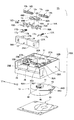
図1乃至図4は、本発明の第1実施形態であるスイッチ1A及び発電装置10Aの構成を説明するための図である。また、図5乃至図11は、本発明の第1実施形態であるスイッチ1A及び発電装置10Aの動作を説明するための図である。
1 to 4 are diagrams for explaining the configuration of a
スイッチ1Aは無線スイッチであり、発電装置10Aと回路基板20とにより構成されている。発電装置10Aは、スイッチレバー12が操作されることにより発電を行うものである。回路基板20は高周波通信回路(図示せず)を設けており、発電装置10Aが発電した電力(誘導起電力)により作動する。
The
この高周波通信回路は、作動することにより電気機器(例えば、照明機器等)に向け2.4GHz帯のスイッチ信号(電波)を送信し、これにより当該電気機器のON操作/OFF操作の二つの操作が行われる構成とされている。この回路基板20は、図3に示すようにケース11の背面側に配設される。
When activated, this high-frequency communication circuit transmits a 2.4 GHz band switch signal (radio wave) to an electrical device (for example, a lighting device), thereby enabling two operations of ON / OFF operation of the electrical device. It is supposed to be done. The
発電装置10Aは、大略するとケース11、スイッチレバー12、発電機13、第1及び第2の発電用ばね14A,14B、スライド部材15、及び第1及び第2の連結解除機構18A,18B等を有した構成とされている。
The
ケース11は樹脂成型品であり、矩形状を有している。このケース11の一側部には、スイッチレバー12を装着するためのレバー装着凹部25が形成されている。このレバー装着凹部25内の中央位置には、スイッチレバー12を軸承する支軸26が立設されている。
The
また、ケース11には、第1及び第2の発電用ばね14A,14Bが装着される第1及び第2のばね収納部27A,27B、第1及び第2のピンホイールばね17A,17Bが装着される第1及び第2のばね装着軸29A,29B、ピンホイールばね17A,17Bの端部17aが係止されるばね係止部30A,30B、発電機13が取り付けられる開口部31、及び発電機13を取り付けるためのボス32A,32B等が一体的に形成されている。
In addition, the
スイッチレバー12は樹脂成型品であり、第1及び第2の操作部35A,35B、軸孔36、第1及び第2の係合凸部37A,37B等を一体的に形成した構成とされている。このスイッチレバー12は、軸孔36を支軸26に挿通することにより支軸26に軸承される。スイッチレバー12はシーソー型のスイッチレバーとされており、よって図2及び図5等に矢印A1,A2で示す方向に揺動する構成とされている。このスイッチレバー12は、請求項に記載の操作部材に相当する。
The
スイッチレバー12に形成された第1及び第2の操作部35A,35Bは、操作者により操作される部位である。本実施形態に係るスイッチレバー12は、支軸26を中心としてA1,A2方向に揺動する構成とされているため、一つのスイッチレバー12により第1の操作部35Aを操作する第1の操作と、第2の操作部35Bを操作する第2の操作の二つの操作を行うことができる。
The first and
第1及び第2の係合凸部37A,37Bは、スイッチレバー12の背面側に形成されている。第1の係合凸部37Aは第1の操作部35Aの反対側に突出した構成とされており、第2の係合凸部37Bは第2の操作部35Bの反対側に突出した構成とされている。
The first and second engaging convex portions 37 </ b> A and 37 </ b> B are formed on the back side of the
また、第1及び第2の操作部35A,35Bを操作することにより発電機13は発電を行うが、第1の操作部35Aを操作した時に発電される電圧特性と、第2の操作部35Bを操作した時に発電される電圧特性は異なっている。これにより、第1の操作と第2の操作を判定することができる。なお、これについては後に詳述する。
The
次に、発電機13について説明する。発電機13は請求項に記載の発電部に相当するものである。この発電機13は、金属製の基板43と装置本体40とを有した構成とされている。
Next, the
また、発電機13には被駆動部41(回転軸)が設けられており、この被駆動部41は基板43から上方に突出した構成とされている。発電機13はモータ式の発電機であり、被駆動部41を回転させることにより、内設されたコイルの内部で磁石が回転し、これにより誘導起電力を発生させる(発電する)。
Further, the
基板43は、複数の装着孔44A〜44Cを有している。発電機13をケース11に固定するには、各装着孔44A〜44Cに図示しない固定ねじを挿通し、この固定ねじをボス32A,32B等に螺着する。また、ケース11の発電機13が取り付けられる部位には、開口部31が形成されている。よって、発電機13がケース11に固定された状態で、被駆動部41は開口部31内に位置した構成となる。更に、被駆動部41には、後述するラック50と噛合するギヤ42が固着されている。
The
第1及び第2の発電用ばね14A,14Bは、請求項に記載の第1及び第2の弾性手段に相当するものである。第1の発電用ばね14Aはケース11に設けられたばね第1のばね収納部27Aに装着され、第2の発電用ばね14Bはケース11に設けられた第2のばね収納部27Bに装着される。この第1及び第2の発電用ばね14A,14Bは、後述するスライド部材15を挟むように配設される。
The first and second power generation springs 14A and 14B correspond to the first and second elastic means described in the claims. The first power generation spring 14 </ b> A is attached to a first spring storage portion 27 </ b> A provided in the
また各発電用ばね14A,14Bは、内側の端部14aがスライド部材15に取り付けられ、外側の端部14bがケース11の内壁に当接するよう構成されている。また各発電用ばね14A,14Bは圧縮されることにより弾性力を蓄積すると共に、この蓄積された弾性力を出力することにより、後述するように発電機13の被駆動部41を回転させて誘導起電力を発生させる構成とされている。
Each of the power generation springs 14 </ b> A and 14 </ b> B is configured such that the
なお、本実施形態では各発電用ばね14A,14Bとして圧縮ばねであるコイルばねを使用しているが、後述する所定の弾性力(弾性エネルギー)を蓄積しうるものであれば、コイルばね以外のばね、ゴム等の弾性部材、又はエアシリンダ等を用いることも可能である。 In this embodiment, coil springs, which are compression springs, are used as the power generation springs 14A and 14B. However, as long as a predetermined elastic force (elastic energy) described later can be accumulated, other than the coil springs are used. It is also possible to use an elastic member such as a spring or rubber, or an air cylinder.
スライド部材15は樹脂成型品であり、本体部47,第1及び第2の接続部48A,48B、第1及び第2の係合部49A,49B、及びラック50等を一体的に形成した構成とされている。
The
本体部47のY2方向端部には第1の係合部49Aが形成されると共に、Y1方向端部には第2の接続部48Bが形成されている。第1の係合部49Aは後述する第1のピンホイール16Aと係合可能な構成とされており、また第2の係合部49Bは後述する第2のピンホイール16Bと係合可能な構成とされている。
A first engaging
また本体部47にはY1,Y2方向に延在するラック50が形成されている。このラック50は、発電機13の被駆動部41に設けられたギヤ42と噛合するよう構成されている。これにより、発電機13とスライド部材15とは、ギヤ42及びラック50を介して接続された構成となる。よって、スライド部材15がY1方向或いはY2方向に移動することにより、スライド部材15はラック50及びギヤ42を介して被駆動部41を回転させ、これにより発電機13は誘導起電力を発生させる。
The main body 47 is formed with a
また、ラック50のY2方向の端部には第1の接続部48Aが形成され、またラック50のY1方向端部には第2の接続部48Bが形成されている。第1の接続部48Aは、第1の発電用ばね14Aの端部14aに嵌合される。これにより、スライド部材15と第1の発電用ばね14Aは接続された構成となる。
A
また、第2の接続部48Bは、第2の発電用ばね14Bの端部14aに嵌合される。これにより、スライド部材15は第2の発電用ばね14Bに接続された構成となる。よって各接続部48A,48Bを各発電用ばね14A,14Bに接続した状態において、スライド部材15は第1の発電用ばね14Aと第2の発電用ばね14Bとの間に挟まれた構成となる。
The
このように、スライド部材15は一対の発電用ばね14A,14B間に挟まれた構成であるため、スライド部材15がY1方向に移動した時には第2の発電用ばね14Bが圧縮されて弾性力を蓄積し、逆にスライド部材15がY2方向に移動した時には第1の発電用ばね14Aが圧縮されて弾性力を蓄積する。
Thus, since the
一方、第1の発電用ばね14Aに蓄積された弾性力が出力されると、スライド部材15は瞬時に矢印Y1方向に移動し、よって前記のようにラック50及びギヤ42を介して被駆動部41は回転付勢され発電機13は誘導起電力を発生させる。また、第2の発電用ばね14Bに蓄積された弾性力が出力されると、スライド部材15は瞬時に矢印Y2方向に移動し、よってラック50及びギヤ42を介して被駆動部41は回転付勢され発電機13は誘導起電力を発生させる。
On the other hand, when the elastic force accumulated in the first
第1の発電用ばね14Aが蓄積された弾性力を出力する際にスライド部材15が移動する方向と、第2の発電用ばね14Bが蓄積された弾性力を出力する際にスライド部材15が移動する方向は反対方向となる。よって、スライド部材15により回転付勢される被駆動軸41の回転方向も、第1の発電用ばね14Aが弾性力を出力する時と、第2の発電用ばね14Bが弾性力を出力する時とで逆の回転方向になる。
The direction in which the
次に、第1及び第2の連結解除機構18A,18Bについて説明する。第1の連結解除機構18Aは、第1のピンホイール16Aと第1のピンホイールばね17A等を有している。この第1の連結解除機構18Aは、スイッチレバー12(第1の係合凸部37A)とスライド部材15とを連結及び連結解除する機能を奏する。
Next, the first and second
また、第2の連結解除機構18Bは、第2のピンホイール16Bと第2のピンホイールばね17B等を有している。この第2の連結解除機構18Bは、スイッチレバー12(第2の係合凸部37B)とスライド部材15とを連結及び連結解除する機能を奏する。
The second
次に、第1及び第2のピンホイール16A,16Bの具体的な構成について説明する。
Next, a specific configuration of the first and
第1及び第2のピンホイール16A,16Bは、いずれも樹脂成型品である。第1のピンホイール16Aは、放射状に延出する複数(本実施形態では5本)の係合突起55A〜55Eが形成されている。また、第1のピンホイール16Aの中心位置は軸孔53Aが形成されており、この軸孔53Aはケース11に形成された第1のホイール軸28Aに挿通される。
The first and
同様に、第2のピンホイール16Bは、放射状に延出する5本の係合突起56A〜56Eが形成されている。また、第2のピンホイール16Aの中心位置には軸孔53Bが形成されており、この軸孔53Bはケース11に形成された第2のホイール軸28Bに挿通される。よって、第1及び第2のピンホイール16A,16Bは、ケース11に回転可能に取り付けられた構成となっている。
Similarly, the
スイッチレバー12がA1方向に操作される際、第1のピンホイール16Aの複数の係合突起55A〜55Eの内、いずれか一の係合突起(図5に示す例では55A)が第1の係合凸部37Aと係合すると共に、他の係合突起(図5に示す例では係合突起55D)がスライド部材15の第1の係合部49Aと係合するよう構成されている。従って、スイッチレバー12がA1方向に操作される際、スイッチレバー12は第1のピンホイール16A及びスライド部材15を介して第2の発電用ばね14B(請求項に記載の第1の弾性手段に相当する)に連結された構成となる。
When the
一方、スイッチレバー12がA2方向に操作される際、第2のピンホイール16Bの複数の係合突起56A〜56Eの内、いずれか一の係合突起(図9に示す例では56A)が第2の係合凸部37Bと係合すると共に、他の係合突起(図9に示す例では係合突起56D)がスライド部材15の第2の係合部49Bと係合するよう構成されている。従って、スイッチレバー12がA2方向に操作される際、スイッチレバー12は第2のピンホイール16B及びスライド部材15を介して第1の発電用ばね14A(請求項に記載の第2の弾性手段に相当する)に連結された構成となる。
On the other hand, when the
第1及び第2のピンホイールばね17A,17Bはトーションばねであり、第1及び第2のピンホイール16A,16Bの近傍位置に配設されている。具体的には、第1のピンホイールばね17Aは第1のばね装着軸29Aに装着されており、端部17aがケース11のばね係止部30Aに係止されると共に、他端17bは第1のピンホイール16Aと係合するよう構成されている。この第1のピンホイールばね17Aは、第1のピンホイール16Aを常に一定方向(図6における反時計方向)に回転付勢する機能を奏する。
The first and second pinwheel springs 17A and 17B are torsion springs, and are disposed in the vicinity of the first and
また、第2のピンホイールばね17Bは第2のばね装着軸29Bに装着されており、端部17aがケース11のばね係止部30Bに係止されると共に、他端17bは第2のピンホイール16Bと係合するよう構成されている。この第2のピンホイールばね17Bは、第2のピンホイール16Bを常に一定方向(図6における時計方向)に回転付勢する機能を奏する。
The second
次に、上記構成とされたスイッチ1A及び発電装置10Aの動作について説明する。
Next, operations of the
図5〜図11は、発電時におけるスイッチ1A及び発電装置10Aの動作を動作順に示している。図5〜図8は、スイッチレバー12を矢印A1方向に操作した時の動作を示しており、図9〜図11はスイッチレバー12を矢印A2方向に操作した時の動作を示している。
5 to 11 show the operations of the
先ず、図5〜図8を用いて、スイッチレバー12を矢印A1方向に操作した時の各構成要素の動作について説明する。
First, the operation of each component when the
図5は、スイッチレバー12をA1方向に操作する直前の状態(以下、第1の操作前状態という)を示している。
FIG. 5 shows a state immediately before the
この第1の操作前状態では、スイッチレバー12は図中矢印A2方向に揺動した状態となっている。また、各ピンホイール16A,16Bはピンホイールばね17A,17Bにより回転付勢されているが、係合突起55A,56Aが各係合凸部37A,37Bと係合することにより回転規制されている。
In the first pre-operation state, the
また第1の操作前状態では、第1及び第2の発電用ばね14A,14Bはいずれも伸長しており、弾性力が蓄積されていない状態である。よって、スライド部材15はその移動範囲の略中央位置(以下、この位置を操作前位置という)に位置した状態となっている。
Further, in the first pre-operation state, the first and second power generation springs 14A and 14B are both extended and no elastic force is accumulated. Therefore, the
ここで、第1の連結解除機構18Aを構成する第1のピンホイール16Aに注目すると、第1のピンホイール16Aの係合突起55Aはスイッチレバー12の第1の係合凸部37Aと係合し、係合突起55Dはスライド部材15の第1の係合部49Aと係合した状態となっている。よって、スイッチレバー12と第2の発電用ばね14Bは、第1の連結解除機構18A(第1のピンホイール16A)及びスライド部材15を介して連結された状態となっている。
Here, paying attention to the
図6は、スイッチレバー12を矢印A1方向に操作し始めた状態を示している。この操作に伴い、第1の係合凸部37Aは係合突起55Aを押圧する。第1のピンホイール16Aは第1のホイール軸28Aに回転可能に取り付けられているため、係合突起55Aが第1の係合凸部37Aに押圧されることにより、図中反時計方向に回転する。
FIG. 6 shows a state in which the
また、第1のピンホイール16Aが回転することにより係合突起55Dも回転し、係合突起55Dと係合している第1の係合部49Aは矢印Y1方向に移動付勢される。これにより、スライド部材15は操作前位置より矢印Y1方向に移動を開始する。
Further, when the
スライド部材15がY1方向にスライドすることにより、スライド部材15の矢印Y1方向側に配設された第2の発電用ばね14BもY1方向に付勢される。しかしながら、第2の発電用ばね14Bの端部14bはケース11の内壁に当接しているため、スライド部材15がY1方向にスライドすることにより第2の発電用ばね14Bは圧縮されて弾性力を蓄積する。
As the
なお、スライド部材15がY1方向に移動することにより、ラック50及びギヤ42を介して被駆動部41も回転するが、スイッチレバー12の操作時におけるスライド部材15の操作力(操作する者による操作力)は小さく安定していないため、発電機13において有効な発電が行われることはない。
When the
図7は、第2の発電用ばね14Bに発電機13を駆動しうる弾性力が蓄積された位置(以下、第1の蓄積完了位置という)までスイッチレバー12を操作した状態(以下、第1の蓄積完了状態という)を示している。
FIG. 7 shows a state in which the
この第1の蓄積完了状態では、スイッチレバー12の第1の操作部35A(第1の係合凸部37A)はA1方向に押し込まれ、これに伴いスライド部材15はY1方向の移動限界位置まで移動した状態となっている。
In the first accumulation completion state, the
本実施形態では、この第1の蓄積完了状態において第2の発電用ばね14Bが最も収縮され、第2の発電用ばね14Bに発電機13を駆動し発電を行いうる弾性力が蓄積されるよう構成されている。また第1の蓄積完了状態では、第1のピンホイール16Aの係合突起55Dは第1の係合部49Aの端部と係合しているが、第1の係合部49Aから離間する直前の状態となっている。
In the present embodiment, in the first accumulation completion state, the second
この第1の蓄積完了位置より、更にスイッチレバー12(第1の係合凸部37A)をA1方向に押し込むと、係合突起55Dは第1の係合部49Aから離間し、スイッチレバー12と第2の発電用ばね14Bとの連結は解除される。このように、係合突起55Dが第1の係合部49Aから離間すると、第2の発電用ばね14Bに蓄積されていた弾性力(弾性エネルギー)はスライド部材15に印加され、スライド部材15は瞬時にY2方向に向け移動する。図8は、スライド部材15がY2方向に移動した状態を示している。
When the switch lever 12 (first engagement
前記のように、ギヤ42とラック50は噛合している。このため、スライド部材15がY2方向に瞬時にスライドすることにより、被駆動部41は図中反時計方向に回転される。よって、発電機13は、第2の発電用ばね14Bが出力する弾性力により誘導起電力を発生させる(発電が行われる)。
As described above, the
この発電時(特に、この時の発電を第1の発電時という)には第1のピンホイール16Aはスライド部材15から離間しているため、スライド部材15には第2の発電用ばね14Bに蓄積された弾性力(弾性復元力)のみが印加される。また、第2の発電用ばね14Bには、発電機13を駆動し発電を行いうる強い弾性力が蓄積されている。このため第1の発電時には、第2の発電用ばね14Bに蓄積された弾性力で発電機13を駆動することにより、安定した高出力の誘導起電力を発生させることができる。
During this power generation (in particular, the power generation at this time is referred to as the first power generation), since the
図12は、第1の発電時に発電機13から出力される誘導起電力の電圧波形を示している。同図において、横軸は時間を示し、縦軸は電圧を示している。前記のように第1の発電時において、発電機13の被駆動部41は図8における反時計方向に回転し、これにより図12に示すような減衰振動波形を有する誘導起電力を発生させる。同図に示すように、第1の発電時における誘導起電力の電圧波形は、先ずマイナスの起電力が発生し、その後にプラス及びマイナスの起電力が交互に発生する。
FIG. 12 shows the voltage waveform of the induced electromotive force output from the
このように第1の発電時に発電機13が誘電起電力を発生することにより、回路基板20に設けられた高周波通信回路は電気機器等(図示せず)に向けて電波を送信する。これにより、例えば電気機器に対して第1の操作(例えば電子機器のON操作)を行うことができる。
As described above, when the
なお、第1の連結解除機構18Aの動作に起因して発電機13が発電を行う際、第2の連結解除機構18Bを構成する第2のピンホイール16Bはスイッチレバー12及びスライド部材15等の駆動を邪魔しないよう構成されている。
When the
次に、図9〜図11を用いてスイッチレバー12を矢印A2方向に操作した時の各構成要素の動作について説明する。
Next, the operation of each component when the
前記のように第1の発電時においてスライド部材15がY2方向に移動すると、その後に第1及び第2の発電用ばね14A,14Bの作用によりスライド部材15はY1,Y2方向に往復減衰運動した後、Y1,Y2方向の略中央位置で停止する。
As described above, when the
図8は、スライド部材15がY1,Y2方向の略中央位置に停止した状態を示している。この図8に示す状態は、スイッチレバー12をA2方向に操作する直前の状態となる(以下、この状態を第2の操作前状態という)。
FIG. 8 shows a state in which the
この第2の操作前状態では、スイッチレバー12は図中矢印A1方向に揺動した状態となっている。また、各ピンホイール16A,16Bはピンホイールばね17A,17Bにより回転付勢されているが、係合突起55B,56Aが各係合凸部37A,37Bと係合することにより回転規制されている。更に、スライド部材15は第1及び第2の発電用ばね14A,14Bにより操作前位置に位置した状態となっている。
In the second pre-operation state, the
また第2の操作前状態では、第2のピンホイール16Bの係合突起56Aがスイッチレバー12の第2の係合凸部37Bと係合し、係合突起56Dがスライド部材15の第2の係合部49Bに係合した状態となっている。よって、スイッチレバー12と第1の発電用ばね14Aは、第2の連結解除機構18B(第2のピンホイール16B)及びスライド部材15を介して連結された状態となっている。
In the second pre-operation state, the
この第2の操作前状態から、スイッチレバー12をA2方向に操作した時の動作は、前記したスイッチレバー12をA1方向に操作した時の動作に対して左右対称な動作となる。以下、具体的な動作について説明する。
From the second pre-operation state, the operation when the
図9は、スイッチレバー12を矢印A2方向に操作し始めた状態を示している。この操作に伴い、第2の係合凸部37Bは係合突起56Aを押圧する。第2のピンホイール16Bは第2のホイール軸28Bに回転可能に取り付けられているため、係合突起56Aが第2の係合凸部37Bに押圧されることにより、図中時計方向に回転する。
FIG. 9 shows a state in which the
第2のピンホイール16Bが回転すると係合突起56Dも回転し、係合突起56Dと係合している第2の係合部49BはY2方向に移動付勢される。これにより、スライド部材15は操作前位置よりY2方向に移動を開始する。また、スライド部材15がY2方向にスライドすると第1の発電用ばね14AもY2方向に付勢され、よって第1の発電用ばね14Aは圧縮されて弾性力を蓄積する。なお、このスライド部材15の移動時も操作者によるスイッチレバー12の操作力は小さく安定していないため、発電機13において有効な発電が行われることはない。
When the
図10は、第1の発電用ばね14Aに発電機13を駆動しうる弾性力が蓄積された位置(以下、第2の蓄積完了位置という)までスイッチレバー12を操作した状態(以下、第2の蓄積完了状態という)を示している。この第2の蓄積完了状態では、スイッチレバー12の第2の操作部35B(第2の係合凸部37B)はA2方向に押し込まれ、これに伴いスライド部材15はY2方向の移動限界位置まで移動した状態となっている。
FIG. 10 shows a state in which the
本実施形態では、この第2の蓄積完了状態において第1の発電用ばね14Aが最も収縮され、第1の発電用ばね14Aに発電機13を駆動し発電を行いうる弾性力が蓄積されるよう構成している。また第2の蓄積完了状態では、第2のピンホイール16Bが第2の係合部49Bから離間する直前の状態となっている。
In the present embodiment, in the second accumulation completion state, the first
この第2の蓄積完了位置から、更にスイッチレバー12(第1の係合凸部37A)をA2方向に押し込むと、係合突起56Dは第2の係合部49Bから離間し、スイッチレバー12と第1の発電用ばね14Aとの連結は解除される。これにより、第1の発電用ばね14Aに蓄積されていた弾性力(弾性エネルギー)はスライド部材15に印加され、スライド部材15は瞬時にY1方向に向け移動する。図11は、スライド部材15がY1方向に移動した直後の状態を示している。
When the switch lever 12 (first engagement
上記のようにスライド部材15がY1方向に瞬時にスライドすることにより、被駆動部41は図中時計方向に回転する。よって、発電機13は、第1の発電用ばね14Aが出力する弾性力により誘導起電力を発生させる(発電が行われる)。
As described above, when the
この発電時(特に、この時の発電を第2の発電時という)には、第2のピンホイール16Bはスライド部材15から離間しているため、スライド部材15には第1の発電用ばね14Aに蓄積された弾性力(弾性復元力)のみが印加される。また、第1の発電用ばね14Aには、発電機13を駆動し発電を行いうる強い弾性力が蓄積されている。このため第2の発電時には、発電機13からは安定した誘導起電力が出力される。
At the time of this power generation (in particular, the power generation at this time is referred to as the second power generation), the
このように第2の発電時に発電機13が誘電起電力を発生することにより、回路基板20に設けられた高周波通信回路は電気機器等(図示せず)に向けて電波を送信する。これにより、例えば電気機器に対して第2の操作(例えば電子機器のOFF操作)を行うことができる。
As described above, when the
なお、第2の連結解除機構18Bの動作に起因して発電機13が発電を行う際、第1の連結解除機構18Aを構成する第1のピンホイール16Aはスイッチレバー12及びスライド部材15等の駆動を邪魔しないよう構成されている。
Note that when the
図13は、第2の発電時に発電機13から出力される誘導起電力の電圧波形を示している。同図において、横軸は時間を示し、縦軸は電圧を示している。前記のように第2の発電時において、発電機13の被駆動部41は図11における時計方向に回転し、これにより図13に示すような減衰振動波形を有する誘導起電力を発生させる。同図に示すように、第2の発電時における誘導起電力の電圧波形は、先ずプラスの起電力が発生し、その後にマイナス及びプラスの起電力が交互に発生する。
FIG. 13 shows the voltage waveform of the induced electromotive force output from the
ここで、図12に示した第1の発電時に発電機13から出力される誘導起電力の電圧波形と、図13に示した第2の発電時に発電機13から出力される誘導起電力の電圧波形を比較する。すると、第1の発電時における誘導起電力の電圧波形と、第2の発電時における誘導起電力の電圧波形は、異なっていることが分かる。具体的には、第1の発電時における電圧波形と第2の発電時における電圧波形は位相が90°ずれていることが分かる。
Here, the voltage waveform of the induced electromotive force output from the
これは、第1の操作部35Aを操作しスイッチレバー12をA1方向に回転操作した時と、第2の操作部35Bを操作しスイッチレバー12をA2方向に回転操作した時で、発電機13が異なる特性を有した起電力を発生させることを示している。よって、発電機13が発生する起電力の特性を検知することにより、第1の操作部35Aを操作する第1の操作と、第2の操作部35Bを操作する第2の操作を判別することが可能となる。
This is because the
回路基板20には、上記の発電機13が発生する起電力の特性に基づき、第1の操作部35Aを操作する第1の操作と、第2の操作部35Bを操作する第2の操作を判別する判別回路が設けられている。
The
このように第1の発電時に発電機13が誘電起電力を発生し、判別回路が発電機13が発生する起電力の特性に基づき操作された操作部35A,35Bを判別することにより、回路基板20に設けられた高周波通信回路は電気機器等(図示せず)に向けて操作された操作部35A,35Bに対応したスイッチ信号(電波)を送信する。これにより、例えば電気機器に対し、第1の操作(例えば電子機器のON操作)、或いは第2の操作(例えば電子機器のOFF操作)を行うことができる。
In this way, the
このように本実施形態では、発電機13の出力により第1の操作と第2の操作を判別可能であるため、スイッチ1Aに第1及び第2の操作を判別するためのセンサを別箇に設ける必要はなくなり、スイッチ1Aの構成の簡単化(部品点数の削減)及び低コスト化を図ることができる。
Thus, in this embodiment, since the first operation and the second operation can be discriminated by the output of the
なお、図11に示す状態は図5に示した第1の操作前状態と等価の状態である。よって、図11に示した状態以降にスイッチレバー12を操作した場合、スイッチ1Aの動作は上記した動作を繰り返し行うこととなる。
The state shown in FIG. 11 is equivalent to the first pre-operation state shown in FIG. Therefore, when the
ところで、上記した実施形態では第1の発電用ばね14Aと第2の発電用ばね14Bのばね定数を等しく設定した例について説明したが、第1の発電用ばね14Aと第2の発電用ばね14Bのばね定数を異ならせることも有効である。
In the above-described embodiment, the example in which the spring constants of the first
この構成とした場合、第1の発電時における電圧波形と第2の発電時における電圧波形は、位相が異なると共に振幅も異なる波形となる。このため、第1の操作と第2の操作の判別をより高い精度で行うことが可能となる。 In this configuration, the voltage waveform during the first power generation and the voltage waveform during the second power generation are waveforms having different phases and different amplitudes. For this reason, it is possible to determine the first operation and the second operation with higher accuracy.
次に、本発明の第2実施形態について説明する。 Next, a second embodiment of the present invention will be described.
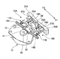
図14乃至図17は、本発明の第2実施形態であるスイッチ1B及び発電装置10Bの構成を説明するための図である。また、図18乃至図29は、本発明の第2実施形態であるスイッチ1B及び発電装置10Bの動作を説明するための図である。
FIGS. 14 to 17 are diagrams for explaining the configuration of the
なお、図14乃至図29において、図1乃至図13に示した構成と対応する構成については同一符号を付し、その説明は省略するものとする。 14 to 29, components corresponding to those shown in FIGS. 1 to 13 are denoted by the same reference numerals, and description thereof is omitted.
本実施形態に係るスイッチ1B及び発電装置10Bは、前記した第1実施形態に係るスイッチ1A及び発電装置10Aと基本的な構成は同一とされている。しかしながら、本実施形態に係るスイッチ1B及び発電装置10Bは、図14に示すように、回路基板20に検出スイッチ100が配設された構成である点、スイッチレバー112を構成する第1の操作部135Aと第2の操作部135Bを分離した構成とした点、第1の操作部135Aにアーム部137Cを設けた点等で異なっている。
The basic configuration of the
検出スイッチ100は、スイッチノブ101を有したマイクロスイッチである。この検出スイッチ100は、スイッチノブ101を操作されることによりON/OFFがされる構成とされている。
The
検出スイッチ100は、回路基板20に配設される。回路基板20は、図14及び図16に示すように切り欠き部20aが形成されている。検出スイッチ100は、スイッチノブ101がこの切り欠き部20a内に突出するよう回路基板20に配設される。なお、検出スイッチ100は、マイクロスイッチのようなメカスイッチに限定されるものではなく、静電容量式、光学式、抵抗式等の各種の検出手段を適用可能なものである。
The
スイッチレバー112は、第1の操作部135A、第2の操作部135B、及びスイッチばね117とにより構成されている。
The
第1の操作部135A及び第2の操作部135Bは樹脂成型品である。第1の操作部135Aは、軸孔136A、第1の係合凸部137A、アーム部137C、及び第1の連結解除機構18Aを一体的に形成した構成とされている。また、第2の操作部135Bは、軸孔136B、第2の係合凸部137B、及び延出部138Bを一体的に形成した構成とされている。
The
第1の操作部135A及び第2の操作部135Bは、軸孔136A,136Bを支軸26に挿通することにより支軸26に軸承される。この際、第1の操作部135Aと第2の操作部135Bとの間にはスイッチばね117が配設される。
The
このスイッチばね117は、第1の操作部135Aを支軸26を中心として図18における時計方向に回転付勢し、第2の操作部135Bを支軸26を中心として図18における反時計方向に回転付勢する。しかしながら、各操作部135A,135Bに形成された延出部138A,138Bが他方の操作部135A,135Bと係合することにより、図18に示す状態以上に回転することはない。
The
アーム部137Cは、下方に向けて(回路基板20の配設位置に向けて)延出するよう構成されている。このアーム部137Cの先端部は、回路基板20に形成された切り欠き部20a内に位置し、検出スイッチ100のスイッチノブ101と対向するよう構成されている(図17参照)。
The
なお、第1の係合凸部137Aは第1実施形態における第1の係合凸部37Aと、また第2の係合凸部137Bは第1実施形態における第2の係合凸部37Bと同一構成とされている。
The first engagement
次に、上記構成とされたスイッチ1B及び発電装置10Bの動作について説明する。
Next, operations of the
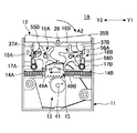
図18〜図29は、発電時におけるスイッチ1B及び発電装置10Bの動作を動作順に示している。図18〜図25は、スイッチレバー112を矢印A1方向に操作した時の動作を示しており、図26〜図29はスイッチレバー112を矢印A2方向に操作した時の動作を示している。また、図18,20,22,24,26,28はスイッチ1B及び発電装置10Bを平面視した図であり、図19,21,23,25,27,29は回路基板20を取り外したスイッチ1B及び発電装置10Bを底面視した図である。
18 to 29 show the operations of the
先ず、図18〜図25を用いて、スイッチレバー112を矢印A1方向に操作した時の各構成要素の動作について説明する。図18及び図19は、第1の操作部135A(スイッチレバー112)をA1方向に操作する直前の状態(第1の操作前状態)を示している。
First, the operation of each component when the
第1の操作前状態では、第1の連結解除機構18Aを構成する第1のピンホイール16Aの係合突起55Aは第1の係合凸部137Aと係合すると共に、係合突起55Dはスライド部材15の第1の係合部49Aと係合した状態となっている。よって、第1の操作部135Aスイッチ(レバー112)と第2の発電用ばね14Bは、第1の連結解除機構18A及びスライド部材15を介して連結された状態となっている。
In the first pre-operation state, the
また第1の操作前状態では、第1及び第2の発電用ばね14A,14Bはいずれも伸長しており、弾性力が蓄積されていない状態である。よって、スライド部材15はその移動範囲の略中央位置(操作前位置)に位置した状態となっている。
Further, in the first pre-operation state, the first and second power generation springs 14A and 14B are both extended and no elastic force is accumulated. Therefore, the
更に第1の操作前状態では、第1の操作部135Aに形成されたアーム部137Cは、図19に示すように、検出スイッチ100のスイッチノブ101から離間した状態となっている。よって、検出スイッチ100は、OFF状態となっている。
Further, in the first pre-operation state, the
図20及び図21は、第1の操作部135Aを矢印A1方向に操作し始めた状態を示している。
20 and 21 show a state in which the
この操作により第1の操作部135Aは支軸26を中心として回転するが、前記のように第2の操作部135Bは第1の操作部135Aと分離独立した構成である。このため、第1の操作部135Aの回転に伴い第2の操作部135Bが回転することはなく、第1の操作前状態を維持する。
By this operation, the
第1の操作部135Aの矢印A1方向への操作に伴い、第1の係合凸部137Aは係合突起55Aを押圧する。係合突起55Aが第1の係合凸部137Aに押圧されることにより、第1のピンホイール16Aは図中反時計方向に回転する。
As the
この回転に伴い係合突起55Dも回転し、係合突起55Dと係合している第1の係合部49Aは矢印Y1方向に移動付勢される。これにより、スライド部材15は操作前位置より矢印Y1方向に移動を開始し、第2の発電用ばね14Bは圧縮されて弾性力を蓄積する。
With this rotation, the
また、スイッチレバー112が矢印A1方向に操作されることにより、アーム部137Cは検出スイッチ100のスイッチノブ101に近接する。しかしながら、第1の操作部135AがA1方向に移動開始した直後においては、図21に示すように、まだスイッチノブ101は押圧されていない状態となっている。よって、検出スイッチ100はOFF状態となっている。
Further, when the
図22及び図23は、第2の発電用ばね14Bに発電機13を駆動しうる弾性力が蓄積された位置(第1の蓄積完了位置)まで第1の操作部135Aを操作した状態(第1の蓄積完了状態)を示している。
22 and 23 show a state in which the
この第1の蓄積完了状態では、第1の操作部135A(第1の係合凸部137A)はA1方向に押し込まれ、これに伴いスライド部材15はY1方向の移動限界位置まで移動した状態となっている。また第1のピンホイール16Aの係合突起55Dは第1の係合部49Aの端部と係合しているが、第1の係合部49Aから離間する直前の状態となっている。
In the first accumulation completion state, the
更に、第1の蓄積完了状態では、図23に示すように、アーム部137Cは検出スイッチ100のスイッチノブ101を押し下げた状態となっている。この第1の蓄積完了状態で検出スイッチ100はON状態となるが、まだ発電機13において発電がされていないため電源供給がおこなわれておらず、検出信号が出力されることはない。
Further, in the first accumulation completion state, as shown in FIG. 23, the
この第1の蓄積完了位置より、更に第1の操作部135AをA1方向に押し込むと、係合突起55Dは第1の係合部49Aから離間する。これにより、第2の発電用ばね14Bに蓄積されていた弾性力(弾性エネルギー)はスライド部材15に印加され、スライド部材15は瞬時にY2方向に向け移動する。
When the
ギヤ42とラック50は噛合しているため、スライド部材15がY2方向に瞬時にスライドすることにより、被駆動部41は図中反時計方向に回転される。よって、発電機13は、第2の発電用ばね14Bが出力する弾性力により誘導起電力を発生させる(発電が行われる)。図24及び図25は、スライド部材15がY2方向に移動した状態を示している。
Since the
このように発電機13が発電を行うことにより、検出スイッチ100にも電源供給が行われる。また上記のように、検出スイッチ100はON状態とされている。このため、検出スイッチ100は電源供給が行われることにより検出信号を出力する。
When the
次に、図26〜図29を用いて第2の操作部135Bを矢印A2方向に操作した時の各構成要素の動作について説明する。
Next, the operation of each component when the
図18及び図19に示した第1の操作前状態から第2の操作部135BをA2方向に操作した時の動作は、前記した第1の操作部135AをA1方向に操作した時の動作に対して左右対称な動作となる。
The operation when the
図26及び図27は、第2の操作部135Bを矢印A2方向に操作した状態を示している。この操作に伴い、第2の係合凸部137Bは係合突起56Aを押圧し、第2のピンホイール16Bは図中時計方向に回転し、係合突起56Dとを介してスライド部材15は操作前位置よりY2方向に移動する。これにより、第1の発電用ばね14Aは圧縮されて弾性力を蓄積する。
26 and 27 show a state where the
図26及び図27に示す位置から、更に第2の操作部135BをA2方向に押し込むと、係合突起56Dは第2の係合部49Bから離間し、スイッチレバー112と第1の発電用ばね14Aとの連結は解除される。
When the
これにより、第1の発電用ばね14Aに蓄積されていた弾性力(弾性エネルギー)はスライド部材15に印加され、スライド部材15は瞬時にY1方向に向け移動し、被駆動部41は図中時計方向に回転する。よって、発電機13は、第1の発電用ばね14Aが出力する弾性力により誘導起電力を発生させる(発電が行われる)。図28及び図29は、スライド部材15がY1方向に移動した直後の状態を示している。
As a result, the elastic force (elastic energy) accumulated in the first
ここで、第2の操作部135Bを矢印A2方向に操作した時のアーム部137C及び検出スイッチ100の動作に注目する。前記のように、アーム部137Cは第1の操作部135Aに一体的に形成されている。よって,第2の操作部135Bを操作しても、アーム部137Cは移動することなく、スイッチノブ101から離間した状態を維持する。即ち、第2の操作部135Bを矢印A2方向に操作されている間は、検出スイッチ100はOFF状態を維持する。
Here, attention is paid to the operation of the
本実施形態に係る判別回路は、発電機13による起電力の発生と、検出スイッチ100の検出結果に基づき、第1の操作部35Aを操作する第1の操作と、第2の操作部35Bを操作する第2の操作を判別する。
The determination circuit according to the present embodiment includes a first operation for operating the
具体的には、発電機13が起電力を発生し、かつ検出スイッチ100がON状態である場合は、判別回路は第1の操作が行われた(第1の操作部135Aが操作された)と判断する。また、発電機13が起電力を発生し、かつ検出スイッチ100がOFF状態である場合は、判別回路は第2の操作が行われた(第2の操作部135Bが操作された)と判断する。
Specifically, when the
この判別回路による判別結果に基づき、回路基板20に設けられた高周波通信回路は電気機器等(図示せず)に向けて操作された操作部35A,35Bに対応したスイッチ信号(電波)を送信する。これにより、例えば電気機器に対し、第1の操作(例えば電子機器のON操作)、或いは第2の操作(例えば電子機器のOFF操作)を行うことができる。
Based on the determination result by the determination circuit, the high-frequency communication circuit provided on the
このように本実施形態では、発電機13の出力を第1の操作或いは第2の操作の判別に用いているため、1個の検出スイッチ100のみで、二つの操作の識別が可能となる。これにより、操作毎に検出スイッチを設ける必要がなくなり、スイッチ1Bの構成の簡単化(部品点数の削減)及び低コスト化を図ることができる。
Thus, in this embodiment, since the output of the
以上、本発明の好ましい実施形態について詳述したが、本発明は上記した特定の実施形態に限定されるものではなく、特許請求の範囲に記載された本発明の要旨の範囲内において、種々の変形・変更が可能なものである。 The preferred embodiments of the present invention have been described in detail above. However, the present invention is not limited to the specific embodiments described above, and various modifications are possible within the scope of the gist of the present invention described in the claims. It can be modified and changed.
本国際出願は2011年1月12日に出願された日本国特許出願2011−004087号に基づく優先権を主張するものであり、日本特許出願2011−004087号の全内容をここに本国際出願に援用する。 This international application claims priority based on Japanese Patent Application No. 2011-004087 filed on January 12, 2011. The entire contents of Japanese Patent Application No. 2011-004087 are incorporated herein by reference. Incorporate.
Claims (6)
第1の操作部と第2の操作部とを有し、発電時に前記第1の操作部又は前記第2の操作部の一方を操作される操作部材と、
被駆動部が駆動されることにより誘導起電力を発生させる発電部と、
前記ケースに第1の方向及びこれと異なる第2の方向に移動可能に設けられており、前記第1の方向又は前記第2の方向に移動することにより前記被駆動部を駆動するスライド部材と、
外力が印加されることにより弾性力を蓄積すると共に蓄積された弾性力を出力することにより前記スライド部材を移動付勢する第1及び第2の弾性手段と、
前記操作部材の前記第1の操作部が操作された際に前記スライド部材を前記第1の方向に移動させることにより前記第1の弾性手段に弾性力を蓄積させ、前記操作部材が蓄積完了位置を過ぎた時に前記操作部材と前記スライド部材との連結を解除し、前記第1の弾性手段に蓄積された弾性力の出力を許容して前記スライド部材を前記第2の方向に移動させる第1の連結解除機構と、
前記操作部材の前記第2の操作部が操作された際に前記スライド部材を前記第2の方向に移動させることにより前記第2の弾性手段に弾性力を蓄積させ、前記操作部材が蓄積完了位置を過ぎた時に前記操作部材と前記スライド部材との連結を解除し、前記第2の弾性手段に蓄積された弾性力の出力を許容して前記スライド部材を前記第1の方向に移動させる第2の連結解除機構と、
を有することを特徴とする発電装置。Case and
An operation member having a first operation unit and a second operation unit, wherein one of the first operation unit and the second operation unit is operated during power generation;
A power generation unit that generates an induced electromotive force by driving the driven unit;
A slide member that is provided in the case so as to be movable in a first direction and a second direction different from the first direction, and that drives the driven part by moving in the first direction or the second direction; ,
First and second elastic means for moving and biasing the slide member by accumulating elastic force by applying an external force and outputting the accumulated elastic force;
When the first operation portion of the operation member is operated, the slide member is moved in the first direction, whereby elastic force is accumulated in the first elastic means, and the operation member is in the accumulation completion position. The first member moves the slide member in the second direction by releasing the connection between the operation member and the slide member when the time passes, and allowing the output of the elastic force accumulated in the first elastic means. A decoupling mechanism of
When the second operation portion of the operation member is operated, the slide member is moved in the second direction, whereby an elastic force is accumulated in the second elastic means, and the operation member is in the accumulation completion position. The second operation of releasing the connection between the operation member and the slide member and allowing the output of the elastic force accumulated in the second elastic means to move the slide member in the first direction. A decoupling mechanism of
A power generator characterized by comprising:
第1の操作部と第2の操作部とを有し、発電時に前記第1の操作部又は前記第2の操作部の一方を操作される操作部材と、
前記第1の操作部又は前記第2の操作部のいずれか一方が操作された際、当該操作された操作部と係合して検出信号を出力する一の検出手段と、
被駆動部が駆動されることにより誘導起電力を発生させる発電部と、
前記ケースに第1の方向及びこれと異なる第2の方向に移動可能に設けられており、前記第1の方向又は前記第2の方向に移動することにより前記被駆動部を駆動するスライド部材と、
外力が印加されることにより弾性力を蓄積すると共に蓄積された弾性力を出力することにより前記スライド部材を移動付勢する第1及び第2の弾性手段と、
前記操作部材の前記第1の操作部が操作された際に前記スライド部材を前記第1の方向に移動させることにより前記第1の弾性手段に弾性力を蓄積させ、前記操作部材が蓄積完了位置を過ぎた時に前記操作部材と前記スライド部材との連結を解除し、前記第1の弾性手段に蓄積された弾性力の出力を許容して前記スライド部材を前記第2の方向に移動させる第1の連結解除機構と、
前記操作部材の前記第2の操作部が操作された際に前記スライド部材を前記第2の方向に移動させることにより前記第2の弾性手段に弾性力を蓄積させ、前記操作部材が蓄積完了位置を過ぎた時に前記操作部材と前記スライド部材との連結を解除し、前記第2の弾性手段に蓄積された弾性力の出力を許容して前記スライド部材を前記第1の方向に移動させる第2の連結解除機構と、
を有することを特徴とする発電装置。Case and
An operation member having a first operation unit and a second operation unit, wherein one of the first operation unit and the second operation unit is operated during power generation;
One detection means for engaging with the operated operation unit and outputting a detection signal when either one of the first operation unit or the second operation unit is operated;
A power generation unit that generates an induced electromotive force by driving the driven unit;
A slide member that is provided in the case so as to be movable in a first direction and a second direction different from the first direction, and that drives the driven part by moving in the first direction or the second direction; ,
First and second elastic means for moving and biasing the slide member by accumulating elastic force by applying an external force and outputting the accumulated elastic force;
When the first operation portion of the operation member is operated, the slide member is moved in the first direction, whereby elastic force is accumulated in the first elastic means, and the operation member is in the accumulation completion position. The first member moves the slide member in the second direction by releasing the connection between the operation member and the slide member when the time passes, and allowing the output of the elastic force accumulated in the first elastic means. A decoupling mechanism of
When the second operation portion of the operation member is operated, the slide member is moved in the second direction, whereby an elastic force is accumulated in the second elastic means, and the operation member is in the accumulation completion position. The second operation of releasing the connection between the operation member and the slide member and allowing the output of the elastic force accumulated in the second elastic means to move the slide member in the first direction. A decoupling mechanism of
A power generator characterized by comprising:
前記ケースに回転可能に取り付けられると共に、回転に伴ない前記操作部材と前記スライド部材とに係合する複数の係合突起が放射状に延出形成されたピンホイールを有することを特徴とする請求項1又は2記載の発電装置。The first and second connection release mechanisms are:
2. A pin wheel which is rotatably attached to the case and has a plurality of engaging projections which radially engage with the operation member and the slide member in association with the rotation. The power generator according to 1 or 2.
前記スライド部材に前記ギヤと噛合するラックを設けたことを特徴とする請求項1又は2記載の発電装置。A gear is disposed on the driven part,
The power generator according to claim 1, wherein a rack that meshes with the gear is provided on the slide member.
前記発電装置が発生させた誘導起電力の特性に基づき、前記第1の操作部又は前記第2の操作部のいずれが操作されたのかを判別する判別回路と、
前記発電装置が発生させる前記誘導起電力により作動すると共に、前記判別回路の判別結果に基づきスイッチ信号を送信する通信回路とを有することを特徴とするスイッチ。A power generator according to claim 1;
A determination circuit for determining which one of the first operation unit and the second operation unit is operated based on the characteristics of the induced electromotive force generated by the power generation device;
And a communication circuit that operates by the induced electromotive force generated by the power generation device and transmits a switch signal based on a determination result of the determination circuit.
前記検出手段の検出結果と前記発電装置が発生する誘導起電力に基づき、前記第1の操作部又は前記第2の操作部のいずれが操作されたのかを判別する判別回路と、
前記発電装置が発生させる前記誘導起電力により作動すると共に、前記判別回路の判別結果に基づきスイッチ信号を送信する通信回路とを有することを特徴とするスイッチ。A power generator according to claim 2;
A determination circuit for determining which one of the first operation unit and the second operation unit is operated based on a detection result of the detection unit and an induced electromotive force generated by the power generation device;
And a communication circuit that operates by the induced electromotive force generated by the power generation device and transmits a switch signal based on a determination result of the determination circuit.
Priority Applications (1)
| Application Number | Priority Date | Filing Date | Title |
|---|---|---|---|
| JP2012552746A JP5590152B2 (en) | 2011-01-12 | 2012-01-11 | Power generation device and switch |
Applications Claiming Priority (4)
| Application Number | Priority Date | Filing Date | Title |
|---|---|---|---|
| JP2011004087 | 2011-01-12 | ||
| JP2011004087 | 2011-01-12 | ||
| PCT/JP2012/050398 WO2012096314A1 (en) | 2011-01-12 | 2012-01-11 | Power generation apparatus and switch |
| JP2012552746A JP5590152B2 (en) | 2011-01-12 | 2012-01-11 | Power generation device and switch |
Publications (2)
| Publication Number | Publication Date |
|---|---|
| JPWO2012096314A1 JPWO2012096314A1 (en) | 2014-06-09 |
| JP5590152B2 true JP5590152B2 (en) | 2014-09-17 |
Family
ID=46507206
Family Applications (1)
| Application Number | Title | Priority Date | Filing Date |
|---|---|---|---|
| JP2012552746A Active JP5590152B2 (en) | 2011-01-12 | 2012-01-11 | Power generation device and switch |
Country Status (3)
| Country | Link |
|---|---|
| US (1) | US9041231B2 (en) |
| JP (1) | JP5590152B2 (en) |
| WO (1) | WO2012096314A1 (en) |
Families Citing this family (14)
| Publication number | Priority date | Publication date | Assignee | Title |
|---|---|---|---|---|
| JP5740897B2 (en) * | 2010-10-04 | 2015-07-01 | ミツミ電機株式会社 | Power generation device and switch |
| JP5853659B2 (en) * | 2011-12-12 | 2016-02-09 | オムロン株式会社 | Power generation module |
| JP2013240266A (en) * | 2012-04-16 | 2013-11-28 | Mitsumi Electric Co Ltd | Power generation device and switch |
| JP5652490B2 (en) * | 2013-03-27 | 2015-01-14 | Toto株式会社 | Remote control device |
| JP5652491B2 (en) * | 2013-03-27 | 2015-01-14 | Toto株式会社 | Remote control device |
| TWI483102B (en) * | 2013-04-15 | 2015-05-01 | Hon Hai Prec Ind Co Ltd | Electronic device and power adapter |
| JP6440088B2 (en) * | 2014-06-05 | 2018-12-19 | Toto株式会社 | Remote control device |
| JP6350052B2 (en) * | 2014-07-11 | 2018-07-04 | Toto株式会社 | Remote control device and toilet system |
| CN104832383B (en) * | 2015-04-28 | 2018-03-13 | 南京邮电大学 | A kind of joint power generation device |
| US10049835B2 (en) * | 2016-02-03 | 2018-08-14 | Texas Scenic Company | Stage curtain motorized rigging limit switch |
| JP6664740B2 (en) * | 2016-04-28 | 2020-03-13 | オプテックス株式会社 | switch |
| CN110768463B (en) * | 2019-10-21 | 2021-02-09 | 德能森智能科技(成都)有限公司 | Signal-enhanced button up-down moving type wireless passive device |
| CN110768462B (en) * | 2019-10-21 | 2021-03-16 | 德能森智能科技(成都)有限公司 | Seesaw type self-generating device with prolonged signal duration |
| US20240072608A1 (en) * | 2022-08-23 | 2024-02-29 | Toto Ltd. | Power generation module and remote control device |
Citations (3)
| Publication number | Priority date | Publication date | Assignee | Title |
|---|---|---|---|---|
| JPS5212807U (en) * | 1975-07-17 | 1977-01-29 | ||
| JPS5656144A (en) * | 1979-10-13 | 1981-05-18 | Eiichi Hirooka | Portable manual generator |
| JP2003164109A (en) * | 2001-11-26 | 2003-06-06 | Machizukuri Keikaku Kenkyusho:Kk | Spiral spring force storage power supply |
Family Cites Families (10)
| Publication number | Priority date | Publication date | Assignee | Title |
|---|---|---|---|---|
| JPS5212807A (en) | 1975-07-21 | 1977-01-31 | Shinshirasuna Denki Kk | Cassette tape recorder |
| FR2802731B1 (en) * | 1999-12-16 | 2002-01-25 | Schneider Electric Ind Sa | AUTONOMOUS REMOTE CONTROL DEVICE, APPARATUS AND ELECTRICAL INSTALLATION COMPRISING SUCH A DEVICE |
| DE10025561A1 (en) | 2000-05-24 | 2001-12-06 | Siemens Ag | Self-sufficient high-frequency transmitter |
| CA2414640A1 (en) * | 2002-12-18 | 2004-06-18 | Beaver Machine Corporation | Electrical generator for a coin mechanism and coin mechanism with an electrical generator and metal detection and release system |
| TWM342866U (en) * | 2008-04-02 | 2008-10-21 | Lightup Technology Co Ltd | Inertia power lighting device |
| FR2953659B1 (en) * | 2009-12-04 | 2011-12-23 | Schneider Electric Ind Sas | ELECTRIC POWER GENERATING DEVICE AND REMOTE CONTROL PROVIDED WITH SUCH A DEVICE |
| JP5740897B2 (en) * | 2010-10-04 | 2015-07-01 | ミツミ電機株式会社 | Power generation device and switch |
| WO2013027161A2 (en) * | 2011-08-23 | 2013-02-28 | Koninklijke Philips Electronics N.V. | An electro-mechanical energy harvesting switch |
| EP2795647B1 (en) * | 2011-12-20 | 2016-03-23 | Koninklijke Philips N.V. | Self-powered energy harvesting switch and method for harvesting energy |
| JP2013240266A (en) * | 2012-04-16 | 2013-11-28 | Mitsumi Electric Co Ltd | Power generation device and switch |
-
2012
- 2012-01-11 WO PCT/JP2012/050398 patent/WO2012096314A1/en active Application Filing
- 2012-01-11 JP JP2012552746A patent/JP5590152B2/en active Active
- 2012-01-11 US US13/977,141 patent/US9041231B2/en active Active
Patent Citations (3)
| Publication number | Priority date | Publication date | Assignee | Title |
|---|---|---|---|---|
| JPS5212807U (en) * | 1975-07-17 | 1977-01-29 | ||
| JPS5656144A (en) * | 1979-10-13 | 1981-05-18 | Eiichi Hirooka | Portable manual generator |
| JP2003164109A (en) * | 2001-11-26 | 2003-06-06 | Machizukuri Keikaku Kenkyusho:Kk | Spiral spring force storage power supply |
Also Published As
| Publication number | Publication date |
|---|---|
| US9041231B2 (en) | 2015-05-26 |
| WO2012096314A1 (en) | 2012-07-19 |
| US20130270092A1 (en) | 2013-10-17 |
| JPWO2012096314A1 (en) | 2014-06-09 |
Similar Documents
| Publication | Publication Date | Title |
|---|---|---|
| JP5590152B2 (en) | Power generation device and switch | |
| CN106067719B (en) | Power generation switch | |
| US8907507B2 (en) | Power generator device and switch | |
| US9106110B2 (en) | Power generating device and switch | |
| JP2011027085A (en) | Engine start/stop switch device | |
| US10775685B2 (en) | Projector | |
| JP2013225831A (en) | Power generation switching system | |
| US20110226599A1 (en) | Portable electronic device | |
| US20140131934A1 (en) | Clamp fixture and related clamp apparatus | |
| WO2017122648A1 (en) | Input device | |
| JP5853659B2 (en) | Power generation module | |
| WO2020080114A1 (en) | Input apparatus | |
| WO2017098704A1 (en) | Power generation device and electronic device provided with same | |
| CN110708900B (en) | Electronic equipment | |
| JP6518944B2 (en) | Power generation unit | |
| JP2008276429A (en) | Push button structure in electronic equipment | |
| WO2012108336A1 (en) | Power generation device and switch | |
| JPWO2018230359A1 (en) | Power switch | |
| JP2009158361A (en) | Sliding electronic component | |
| US20130208177A1 (en) | Electronic apparatus having operation portion | |
| JP2007027060A (en) | Input device | |
| JP2007027059A (en) | Input device | |
| JP2008098043A (en) | Composite operation type input device | |
| JP6123499B2 (en) | External circuit handle device for circuit breaker | |
| WO2018230360A1 (en) | Power generation device |
Legal Events
| Date | Code | Title | Description |
|---|---|---|---|
| TRDD | Decision of grant or rejection written | ||
| A01 | Written decision to grant a patent or to grant a registration (utility model) |
Free format text: JAPANESE INTERMEDIATE CODE: A01 Effective date: 20140701 |
|
| A61 | First payment of annual fees (during grant procedure) |
Free format text: JAPANESE INTERMEDIATE CODE: A61 Effective date: 20140714 |
|
| R150 | Certificate of patent or registration of utility model |
Ref document number: 5590152 Country of ref document: JP Free format text: JAPANESE INTERMEDIATE CODE: R150 |
|
| R250 | Receipt of annual fees |
Free format text: JAPANESE INTERMEDIATE CODE: R250 |