EP2795647B1 - Self-powered energy harvesting switch and method for harvesting energy - Google Patents
Self-powered energy harvesting switch and method for harvesting energy Download PDFInfo
- Publication number
- EP2795647B1 EP2795647B1 EP12818930.5A EP12818930A EP2795647B1 EP 2795647 B1 EP2795647 B1 EP 2795647B1 EP 12818930 A EP12818930 A EP 12818930A EP 2795647 B1 EP2795647 B1 EP 2795647B1
- Authority
- EP
- European Patent Office
- Prior art keywords
- actuation
- moving device
- drive unit
- switch
- energy
- Prior art date
- Legal status (The legal status is an assumption and is not a legal conclusion. Google has not performed a legal analysis and makes no representation as to the accuracy of the status listed.)
- Not-in-force
Links
Images

Classifications
-
- H—ELECTRICITY
- H01—ELECTRIC ELEMENTS
- H01H—ELECTRIC SWITCHES; RELAYS; SELECTORS; EMERGENCY PROTECTIVE DEVICES
- H01H25/00—Switches with compound movement of handle or other operating part
- H01H25/06—Operating part movable both angularly and rectilinearly, the rectilinear movement being along the axis of angular movement
-
- H—ELECTRICITY
- H02—GENERATION; CONVERSION OR DISTRIBUTION OF ELECTRIC POWER
- H02K—DYNAMO-ELECTRIC MACHINES
- H02K35/00—Generators with reciprocating, oscillating or vibrating coil system, magnet, armature or other part of the magnetic circuit
-
- H—ELECTRICITY
- H02—GENERATION; CONVERSION OR DISTRIBUTION OF ELECTRIC POWER
- H02K—DYNAMO-ELECTRIC MACHINES
- H02K7/00—Arrangements for handling mechanical energy structurally associated with dynamo-electric machines, e.g. structural association with mechanical driving motors or auxiliary dynamo-electric machines
- H02K7/18—Structural association of electric generators with mechanical driving motors, e.g. with turbines
- H02K7/1869—Linear generators; sectional generators
- H02K7/1876—Linear generators; sectional generators with reciprocating, linearly oscillating or vibrating parts
-
- H—ELECTRICITY
- H02—GENERATION; CONVERSION OR DISTRIBUTION OF ELECTRIC POWER
- H02K—DYNAMO-ELECTRIC MACHINES
- H02K7/00—Arrangements for handling mechanical energy structurally associated with dynamo-electric machines, e.g. structural association with mechanical driving motors or auxiliary dynamo-electric machines
- H02K7/18—Structural association of electric generators with mechanical driving motors, e.g. with turbines
- H02K7/1892—Generators with parts oscillating or vibrating about an axis
-
- H—ELECTRICITY
- H01—ELECTRIC ELEMENTS
- H01H—ELECTRIC SWITCHES; RELAYS; SELECTORS; EMERGENCY PROTECTIVE DEVICES
- H01H2239/00—Miscellaneous
- H01H2239/076—Key stroke generating power
-
- H—ELECTRICITY
- H01—ELECTRIC ELEMENTS
- H01H—ELECTRIC SWITCHES; RELAYS; SELECTORS; EMERGENCY PROTECTIVE DEVICES
- H01H2300/00—Orthogonal indexing scheme relating to electric switches, relays, selectors or emergency protective devices covered by H01H
- H01H2300/03—Application domotique, e.g. for house automation, bus connected switches, sensors, loads or intelligent wiring
- H01H2300/032—Application domotique, e.g. for house automation, bus connected switches, sensors, loads or intelligent wiring using RFID technology in switching devices
-
- H—ELECTRICITY
- H01—ELECTRIC ELEMENTS
- H01H—ELECTRIC SWITCHES; RELAYS; SELECTORS; EMERGENCY PROTECTIVE DEVICES
- H01H2300/00—Orthogonal indexing scheme relating to electric switches, relays, selectors or emergency protective devices covered by H01H
- H01H2300/052—Controlling, signalling or testing correct functioning of a switch
-
- H—ELECTRICITY
- H02—GENERATION; CONVERSION OR DISTRIBUTION OF ELECTRIC POWER
- H02K—DYNAMO-ELECTRIC MACHINES
- H02K2201/00—Specific aspects not provided for in the other groups of this subclass relating to the magnetic circuits
- H02K2201/18—Machines moving with multiple degrees of freedom
-
- Y—GENERAL TAGGING OF NEW TECHNOLOGICAL DEVELOPMENTS; GENERAL TAGGING OF CROSS-SECTIONAL TECHNOLOGIES SPANNING OVER SEVERAL SECTIONS OF THE IPC; TECHNICAL SUBJECTS COVERED BY FORMER USPC CROSS-REFERENCE ART COLLECTIONS [XRACs] AND DIGESTS
- Y02—TECHNOLOGIES OR APPLICATIONS FOR MITIGATION OR ADAPTATION AGAINST CLIMATE CHANGE
- Y02B—CLIMATE CHANGE MITIGATION TECHNOLOGIES RELATED TO BUILDINGS, e.g. HOUSING, HOUSE APPLIANCES OR RELATED END-USER APPLICATIONS
- Y02B90/00—Enabling technologies or technologies with a potential or indirect contribution to GHG emissions mitigation
- Y02B90/20—Smart grids as enabling technology in buildings sector
-
- Y—GENERAL TAGGING OF NEW TECHNOLOGICAL DEVELOPMENTS; GENERAL TAGGING OF CROSS-SECTIONAL TECHNOLOGIES SPANNING OVER SEVERAL SECTIONS OF THE IPC; TECHNICAL SUBJECTS COVERED BY FORMER USPC CROSS-REFERENCE ART COLLECTIONS [XRACs] AND DIGESTS
- Y04—INFORMATION OR COMMUNICATION TECHNOLOGIES HAVING AN IMPACT ON OTHER TECHNOLOGY AREAS
- Y04S—SYSTEMS INTEGRATING TECHNOLOGIES RELATED TO POWER NETWORK OPERATION, COMMUNICATION OR INFORMATION TECHNOLOGIES FOR IMPROVING THE ELECTRICAL POWER GENERATION, TRANSMISSION, DISTRIBUTION, MANAGEMENT OR USAGE, i.e. SMART GRIDS
- Y04S20/00—Management or operation of end-user stationary applications or the last stages of power distribution; Controlling, monitoring or operating thereof
- Y04S20/14—Protecting elements, switches, relays or circuit breakers
Definitions
- the present invention relates to a self-powered switch device and a method of generating energy, especially energy required for operation and communication and interaction with an operator.
- Wireless switches, remote controls, sensors, energy control devices or the like which are self-powered provide the advantage of device positioning independently of specific energy supply situations like cables or power outlets.
- the installation locations can be chosen and determined regardless of any power supply constraints, and even portable respectively mobile control and sensing devices can be provided.
- switch devices are battery-operated, with lifetime dependent on power supply, and replacement of batteries is required, usually after an uncertain time period. Such replacement operations implicate time-consuming and laborious and costly installation work, depending on the location of each switch. Therefore, self-powered devices offer a promising alternative in order to reduce the operating expense of sensing and control systems, e.g. in the field of facility management.
- dial dimmer switches can be used for e.g. lighting control, having one ore more knobs for adjusting power supply, e.g. for lighting from full light to very dim and all brightness measures in between, and these switches can be combined with rotary dimmer switches.
- the switches can be provided as slide dimmer switches having a sliding handle for continuously adapting the level of supplied power, also in conjunction with a separate button for on/off function.
- touch pad dimmers can be provided for adjusting power supply in dependence on any position of a user's finger on the pad, and these touch pad dimmers can advantageously be used e.g.
- plug-in dimmer switches can be installed between a power supply outlet and a consumer load, representing the simplest way to provide a power control in case sockets are provided. They do not require any installation at all, as they can directly be plugged between a consumer load and an outlet of a power network.
- the ECO100/EC0200 is provided with an electro-dynamic energy converter for linear motion which is actuated by a spring which can be pushed from outside the device. It can be used to power the PTM230/PTM330/PTM332 transmitter module, sending - when an energy pulse is supplied - an RF telegram which is transmitted including a unique 32-bit module ID, the polarity of the energy pulse, and the operating status of four contact nipples.
- the document " US 2004/174287 A1 " discloses a switch device according to the premble of claim 1.
- An object of the present invention is to provide a wireless switch device which is simple for the user to operate and robust, wherein energy required for operation, e.g. sending control commands, can be generated by the device itself.
- a further object of the present invention is to provide an energy harvesting device for a switch device which allows for realizing an on/off function and preferably also a dimming function in an intuitive and convenient way for a user.
- a further object of the present invention is to provide a device for harvesting energy for a switch device which is self-powered, wherein the device for harvesting energy can ensure that upon operation of a knob by a user, electric energy can be provided for wireless operation of the switch device.
- a switch device comprising a drive unit configured to interact with an actuation device operable by external force, e.g. by a human user or machine movement, and provided at the switch device, a moving device configured to be set in motion by the drive unit, an energy harvester coupled with the moving device, for providing electric energy to the switch device responsive to a motion of the moving device, and a position return device coupled to the moving device, wherein the moving device is configured to be repositioned by the position return device in relation to a defined zero position.
- the moving device can be brought back to a zero position, in order to be set in motion again responsive to a further actuation.
- the position return device can be configured to repeatedly bring back the moving device to the zero position.
- the moving device does not necessarily have to oscillate for a plurality of times. Also, only one single relative movement can provide for energy.
- the energy harvester is configured to provide energy to the switch device e.g. for transmitting a command based on the operation of a user.
- an electromechanical arrangement is provided for conversion of kinetic energy in electric energy.
- the drive unit is coupled to the actuation device.
- the drive unit can be coupled to the actuation device in such a way that a specific motion of the actuation device evokes a specific motion of the drive unit.
- the drive unit can be coupled rigidly to the actuation device, and the coupling can be provided in the form of interdependent profiles respectively lateral areas at each of the drive unit and actuation device and which interact with each other.
- the moving device can be set in a motion responsive to a specific amount of motion of the drive unit. Once set in motion, the moving device can move independently from any motion of the drive unit. In one embodiment, the moving device can move as long as it has kinetic energy which can be converted in electric energy.
- the moving device can be suspended elastically, whereas the drive unit is suspended rigidly.
- the moving device and the energy harvester can constitute the main components of an electromechanical arrangement, but also the energy harvester itself can constitute the main components of an electromechanical arrangement for providing electric energy.
- the energy harvester can be arranged in the area of a zero position of the moving device.
- the zero position of the moving device can correspond to a zero position of the energy harvester.
- the moving device is moved out of its zero position by a motion of the drive unit, and when disengaged by the drive unit, it returns quickly to the zero position thanks to the position return device, thus harvesting energy.
- the actuation device is operable, especially by an external force, e.g. a user, in both rotational directions around an actuation axis, wherein the drive unit engages with the moving device in the same way, so that energy is provided to the switch independent of the direction of rotation.
- the moving device when the actuation device is rotated by external force, e.g. a user, the moving device is set in motion. In particular, it depends on the exact shape and dimensions of the protrusion and the recess portions engaging each other to what extend the motion of the moving device is coupled to the rotation and/or actual position of the driving unit. In dependence on the amount of the angle with which the actuation device is rotated, the moving device can be set in motion to oscillate freely, or set in motion only to an extend corresponding to a specific angle with which the actuation device is rotated.
- the drive unit can decouple from the actuation device. This can be done by a mechanism which separates the actuation device and the drive unit in dependence on the angle of rotation so that the drive unit can rotate automatically independent from the position of the actuation device.
- the connection between the actuation device and the drive unit is reconstituted, especially by engaging back in a gearing or the like.
- the components of the switch device can be arranged such that the moving device consists of an intermediate member between the drive unit and the energy harvester.
- the drive unit can be rotated around an axis which is orthogonal to >an axis along/to the plane in which the moving device is set in motion, and the energy harvester can be rotated around an axis which is parallel to the rotation axis of the drive unit.
- the drive unit can be rotated around an axis which is parallel to an axis of rotation of the moving device.
- the switch device can be provided with an energy storage.
- the energy storage can store the excess energy, not consumed during the processing, storing, signal transmission, provisioning of feedback and/or other handling operations triggered by the switch actuation.
- the stored energy can subsequently be used, e.g. for maintenance operations like processing, signal transmission and/or signal reception, for provisioning of feedback, and the like.
- the energy storage can provide energy for a command instantaneously in reaction on a user's actuation of the actuation device. Electric energy provided by a motion of the moving device in response to this user's actuation can be stored in the energy storage in order to provide and keep at hand energy for a prospective command.
- the energy storage can be coupled with the energy harvester.
- the actuation device is operable, especially by a user, in a rotational direction around an actuation axis and in a translational direction along the actuation axis.
- energy can be generated both responsive to rotation and pushing or releasing.
- a mechanical blocking device is provided between the actuation device and the drive unit in order to prevent rotation of the actuation device when the actuation device is operated along the translational direction.
- the actuation device is provided with a screw thread configured to connect the drive unit with the actuation device.
- the drive unit can be set in motion responsive to a translational actuation of the actuation device.
- the drive unit can be hold in a specific position with respect to a corpus of the switch device when the actuation device is pressed or released.
- the drive unit can be retained by an inner wall of the switch device, and at the same time, the actuation device can engage in recesses provided in the corpus of the switch device, in order to prevent rotation.
- an interlocking device can be provided at the actuation device for preventing relative movement between the drive unit and the actuation device. Thereby, it can be ensured that a rotational movement of the actuation device can be transmitted in a conformal way in a corresponding rotational movement of the drive unit.
- the actuation device is provided with a shaft which extends along an actuation axis of the actuation device and which is movably arranged within a corpus of the switch device, and wherein an elastic element is provided at the shaft between the actuation device and the corpus, especially for preventing movement of the actuation device along the actuation axis.
- the actuation device is elastically arranged within a corpus of the switch device, and wherein a blocking element is provided at the actuation device, for preventing relative movement between the actuation device and the corpus of the switch, especially in a translational direction.
- the blocking element can be provided in the form of a snap ring or locking ring.
- the elastic arrangement can be realized by a spring acting on a wall of the corpus, especially from one side, and the blocking element can be provided at the other side of the wall. Thereby, support of the actuation device within the switch device can be ensured, and the actuation device can easily be mounted at the corpus.
- the switch can contain one or more group of: energy conditioning element (e.g. a DC/DC converter), processing unit, memory, feedback means (e.g. LED diodes), further hardware means for interaction with the switch (e.g. dip switches or pinhole contact, e.g. for switch configuration).
- the switch device can include an emitter, and the energy can be provided for emitting control commands by a communication interface (e.g. a wireless communication interface according to 802.15.4/ZigBee Green Power protocol suite).
- the communication interface can be provide for at least one out of the group of secure communication over radio, bidirectional communication with from and to the switch device for commissioning and/or maintenance of network parameters, and frequency agility.
- the switch device further comprises a sensor configured to detect an actuation and to differentiate between rotational actuation around an actuation axis and actuation along the actuation axis. Both operation types can result in different control commands being generated.
- the switch provides for translating the actuation operations into more than one action.
- the action is transmission of a control signal, preferably a wireless control signal, and the translational movement results different action than the rotational movement.
- the translational movement may result in transmission of an on/off or toggle command, and the rotational movement in a dimming up/down operation, depending on the CW/CCW direction of the rotation.
- a combination of both types of movements can provide for further control operation.
- Electronic means to differentiate the operations may be provided in a plurality of different forms, e.g. contacts, diodes, sensors.
- the one or more actuations can result in one or more of operations from a group comprising: measurement, calculation, storage, physical indication, physical actuation and communication,
- the switch device can be provided for the management of facilities and/or complete buildings.
- the moving device is provided with at least one protrusion which is configured to engage in recess portions of the drive unit.
- the moving device can be set in motion responsive to a specific motion of the drive unit, so that a considerable motion of the drive unit provides for a considerable amount of kinetic energy of the moving device.
- the recess portion can be provided as a part of a gear wheel.
- the energy harvester can be configured to convert kinetic energy of the moving device into electric energy provided for operation of the switch device.
- the protrusion can be provided with a symmetric shape with respect to an x-axis pointing in the direction of the drive unit, the x-axis being orthogonal to a y-axis along which the moving device carries out a translational movement, and the x-axis being orthogonal to a z-axis around which the drive unit is actuated for rotation.
- the protrusion can be provided in the form of a bar, a protruding rib, or a rim, or the like, from which the axis of symmetry coincides with an axis defining the zero position.
- the geometry respectively shape of the moving device can be described by a T-profile, the upper bar of the T being suspended between position return devices, and the protrusion arranged orthogonally to the upper bar.
- the drive unit can be provided with a symmetric shape with respect to the z-axis, so that the moving device is set in motion by the drive unit in the same way independent of a rotational direction around the z-axis in which the drive unit is actuated by a user, and also independent of any linear, translational direction in which the actuation device can be actuated by a user. Also, not only rotation, but also linear actuation can result in rotation around the actuation axis and in a rotation of the drive unit.
- the recess portions can have a symmetric shape with respect to an axis passing the zero position and the actuation axis of the drive unit, so that the moving device is set in motion in a respective translational direction in the same way when the actuation device is rotated by a user. Thereafter, the moving device can move in both translational direction, wherein the motion can be an oscillation, and this oscillation can be independent of the exact position of the actuation device. Thereby, energy can be provided to the switch device independent of the kind of actuation of a user.
- the position return device coupled to the moving device is composed of one or several mechanical elements, wherein the mechanical elements provide forces counteracting the motion respectively rotation of the drive unit.
- an electromechanical arrangement can be provided which ensures that the moving device always reaches a zero position and rests in the zero position, when there is no actuation by a user.
- the position return device is provided for bringing back the moving device towards a zero position in such a way that a restoring force is smaller than the force of inertia of the moving device, once the moving device has been set in motion by the drive unit.
- kinetic energy of the moving device can be conversed in electric energy over a period of a certain length of time, as the moving device holds on moving for a certain length of time.
- the position return device is provided for bringing back the moving device towards a zero position in such a way that a restoring force is greater than the force of inertia of the moving device, and thus the moving device immediately and quickly returns to the zero position.
- the kinetic energy of the moving device returning to its zero position preferably resulting - directly or indirectly, via another kinetic energy coupling - in change of electromagnetic field can be conversed in electric energy.
- the position return device is composed of one or several elastic mechanical elements.
- the position return device can be provided in the form of one or several springs, especially extension springs.
- the position return device can be coupled to the moving device at two opposing ends of the moving device.
- the position return device is coupled to the moving device at only one end or one portion for coupling the position return device to the moving device.
- the energy harvester is composed of a magnetic block arranged at the moving device and at least one conducting element, e.g. generator coil, with respect to which the magnetic block moves.
- a magnetic block arranged at the moving device and at least one conducting element, e.g. generator coil, with respect to which the magnetic block moves.
- the moving device also can be constituted by the magnetic block, at least to a major extend.
- the moving device is supported in guidance like guides, guide contacts or slides which extent orthogonal to a rotation axis of the drive unit, such that the moving device is moved in a translational direction when the actuation device is rotated by a user
- the energy harvester is composed of a rack portion provided on the moving device. This ensures that the moving device moves along a defined translational axis, and that no energy is dissipated because of any uncontrolled lateral motion of the moving device.
- the energy harvester can be composed of a generator which is actuated around a generator axis by the rack portion in dependence on motion of the moving device.
- a gear wheel can be arranged at the generator, and the rack portion can engage the gear wheel.
- the method for providing energy to a switch device for wireless operation of the switch device by an electromechanical arrangement provided within the switch device comprises the steps of actuating a drive unit mechanically interacting with an actuation device responsive to an operation of the actuation device of the switch device by a user, and responsive to the actuation of the drive unit, setting in motion of a moving device engaging the drive unit, and responsive to the motion of the moving device, harvesting energy for wireless operation of the switch device by relative movement of the moving device with respect to an energy harvester, and repeatedly reposition the moving device in relation to a defined zero position by a position return device.
- This ensures that in reaction on a user's input, electric energy is provided to the switch device by direct conversion of kinetic or mechanical energy.
- the energy harvester is actuated by the moving device for the time the moving device is moving, and kinetic energy of the moving device is converted in electric energy by the energy harvester.
- the moving device can be constantly brought back to the zero position, as long as kinetic energy is provided.
- the energy harvester can be moved by the moving device with respect to a zero position of the energy harvester. Thereby, it can be ensured that a high amount of the kinetic energy of the moving device can be deployed for providing electric energy to the switch device.
- the switch device can be provided for power control based on commands emitted by the switch device within a network of a plurality of switch devices.
- the moving device can be constantly brought back to the zero position by a position return device configured to bring back the oscillation device contrary to both oscillation directions, so that the switch device can be operated by a user based of at least two different user commands respectively user inputs.
- the moving device can be positioned between the drive unit and the energy harvester, or it can also include components of the energy harvester. Of course, use for other applications and other measuring parameters is possible as well.
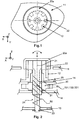
- Fig. 1 shows a schematic top view of a switch device provided in the form of a knob which can be actuated both in a translational direction and rotationally around an actuation axis, to which the invention can be applied.
- the switch device is provided with a mechanical blocking device 12 arranged within the switch device behind the device surface 11.
- An actuation device 20a is configured to engage with the mechanical blocking device 12 when the actuation device 20a is pressed and moved in a direction opposite to the z-direction. This can be realized by a structured inner profile 22 of the actuation device 20a corresponding to a likewise structured outer profile of the mechanical blocking device 12.
- Fig. 2 shows a cross-sectional side view of the actuation device 20a supported around and connected to an actuation axis 21, wherein the actuation device 20a is provided as a component of a switch device, here the switch device housing indicated by a device surface 11 and several internal walls 13, 14.
- the actuation device 20a comprises a shaft 24 which is supported in at least one of the walls 13, 14.
- the actuation device 20a is configured to be actuated in a rotation direction around the actuation axis 21 and in a translational direction, whereby the translational direction corresponds to a direction opposite to the z-axis of a coordinate system which defines the surface of a switch device by its x-y-plane, the x-axis facing towards the left side, and the y-axis facing opposite to the viewing direction in which Fig. 2 can be viewed.
- the z-axis is facing vertically upwards.
- the switch device is provided with the mechanical blocking device 12 arranged within the switch device behind the device surface 11.
- the actuation device 20a is configured to engage with the mechanical blocking device 12 when the actuation device 20a is pressed and moved in a direction opposite to the z-direction.
- the mechanical blocking device 12 can be part of an inner wall of the switch device.
- the actuation device 20a further comprises a screw thread 25 for ensuring that the drive unit 20 can be coupled to the actuation device 20a.
- the screw thread 25 can be provided in such a way that when the actuation device 20a is pressed along its actuation axis 21, the drive unit 20 is rotated around the Z-axis and at the same time hold in position with respect to a corpus 11, 13, 14 of the switch device.
- the drive unit 20 can be prevented from moving along the actuation axis 21 in Z direction, especially by inner wall 14 and the wall above part 20.
- the actuation device 20a engages with recesses 12 at the corpus, especially at inner wall 14.
- the drive unit 20 can be provided with an inner screw thread also. Also another type of shape can be on shaft 21 and 20 to transform translation into a rotation. A pin 31 on 20 in a grove on 21 is also possible.
- the actuation device 20a can be brought back to a zero position when it has been pressed and moved in a direction to the z-direction, especially by an elastic element 50 which can be provided in the form of a strong spring, also preventing the actuation device 20a from being inadvertently pressed during rotation.
- the elastic element 50 can be provided in the form of a spring arranged around the shaft 24 and arranged between the screw thread 25 and one of the inner walls, especially wall 13.
- the elastic element 50 provides for a position return arrangement for bringing back the actuation device 20a along a translational direction, especially along the rotational axis 21.
- a blocking element 23 can be provided on the shaft 24 at a position behind the wall 13.
- the drive unit 20 can be rotated likewise, especially when an interlocking device 31 is provided, e.g. in the form of a pin engaging the drive unit 20 in rotation.
- a moving device 131; 231 can be moved. The motion of the moving device 131; 231 can provide for generating electric energy.
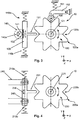
- Fig. 3 shows a drive unit 120 according to a first embodiment provided in the form of a gear wheel with recess portions 120b and protruding portions 120a.
- This gear wheel shown as 120 in Fig.3 is also shown in Fig.1 as drive unit 20.
- the gear wheel 120 can be actuated around a rotation axis 121 by a force, e.g. a user, especially in both rotational directions, and in particular by an actuation device, as can be seen in Fig 1 , interacting with the drive unit 120.
- a moving device 130 is provided in the form of a block with a protrusion 131 protruding from the block in an x-direction towards the drive unit 120 into one of the recess portions 120b.
- the moving device 130 is arranged such that the protrusion 131 rests in a zero position with respect to an y-axis facing in a directing in which the moving device 130 can be set in motion by the drive unit 120, whereby the rotational movement of the drive unit 120 by a sufficient angle causes engaging the moving device 130 with at least one of the protruding portions 120a. Once disengaged from one of the protruding portions 120a as the rotational movement continues, the moving device 130 moves within the recess portions 120b, to finally assume the zero position.
- a position return device 110 is provided.
- the position return device is advantageously realized in form of two position return devices 110a, 110b provided at opposing ends of the moving device 130.
- the position return devices 110a, 110b can be provided in the form of positioning springs, which are advantageously configured to apply a force of attraction to the moving device 130, in order to bring back the moving device 130 to the zero position when no force in the y-direction is applied to the protrusion 131. It is not necessary to have two springs, one spring 110a or 110b connected to the housing and to portion 130 also provides the function of bringing back portion 130 in rest position.
- the protrusion 131 and the recess portions 120b can be designed such that the moving device 130 can only move when the drive unit 120 is rotated.
- the protrusion 131 and the recess portions 120b can be designed such that a motion of the moving device 130 (at least to a certain extend) can be realized also in case the drive unit 120 is not rotated. This can provide the advantage of generating energy also in case there is only a rotation of a small angle, as the moving device 130 can oscillate to a certain extend while the protrusion engages in one of the recess portions 120b and remains within one of the recess portions 120b.
- the moving device 130 is provided with a rack portion 132, especially on a side surface of the moving device 130 opposed to the side of the moving device 130 from which the protrusion 131 protrudes. That is to say, the rack portion 132 can be provided at a side which is facing opposed to the x-direction.
- a generator device 140 is provided which is configured to rotate around a generator axis 141.
- the generator device 140 has an engaging element 140a which is configured to interact with the rack portion 132.
- the engaging element 140a is provided in the form of a gear wheel.
- Energy for the switch device can be generated by converting mechanical energy respectively kinetic energy into electrical energy, which can be done by an energy harvester. According to the embodiment of Fig.
- the energy harvester can be composed of the generator device 140 and the rack portion 132 and both positioning devices 110a, 110b.
- a force e.g. spring or elastic member 151
- the position of the wheel can be controlled by connecting the wheel to a lever 152, or also a linear guidance is possible.
- the mechanical coupling between the moving device 130 and the generator device 140 can be realized by alternative couplings.
- the rack portion 132 is likely to be only one of the possible electromechanical arrangements.
- Fig. 4 basically shows a drive unit according to a second embodiment with a configuration like the one shown in Fig. 3 , but there is a difference with respect to the energy harvester.
- Fig. 4 shows a drive unit 220 provided in the form of a gear wheel with recess portions 220b and protruding portions 220a.
- the gear wheel 220 can be actuated around a rotation axis 221 by a force, e.g. by a user, especially in both rotational directions, and in particular by an actuation device (not shown) interacting with the drive unit 220.
- a moving device 230 is provided in the form of a magnetic block with a protrusion 231 protruding from the magnetic block in an x-direction towards the drive unit 220 and engaging in one of the recess portions 220b.
- the moving device 230 is arranged such that the protrusion 231 rests in a zero position with respect to a y-axis facing in a directing in which the moving device 230 can be set in motion by the drive unit 220.
- two position return devices 210a, 210b are provided at opposing end portions of the moving device 230.
- the position return devices 210a, 210b can be provided in the form of positioning springs, which are advantageously configured to apply a force of attraction to the moving device 230, in order to bring back the moving device 230 to the zero position when no force in a y-direction is applied to the protrusion 231.
- the protrusion 231 and the recess portions 220b can be designed such that the moving device 230 can only move when the drive unit 220 is rotated.
- the protrusion 231 and the recess portions 220b can be designed such that a motion of the moving device 230 (at least to a certain extend) can be realized also in case the drive unit 220 is not rotated. This can provide the advantage of generating energy also in case there is only a rotation of a small angle, as the moving device 230 can oscillate to a certain extend while the protrusion engages in one of the recess portions 220b and remains within one of the recess portions 220b.
- a generator device 240 is provided which is configured to generate electric energy based on a relative movement of the moving device 230 with respect to the generator device 240.
- Energy for the switch device can be generated by converting mechanical energy respectively kinetic energy into electrical energy, which can be done by the energy harvester.
- the generator device 240 is provided in the form of one or more conducting structures, e.g. coils, which are arranged around the oscillator device 230, especially the magnetic part of the oscillator device 230. By moving the oscillator device 230 relatively to the coils 240, a current can be induced in the coils, providing electric energy for the switch device.
- the energy harvester can be composed of the generator device 240 and the moving device 230 itself and both positioning devices 210a, 210b.
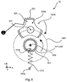
- Fig. 5 shows a drive unit 320 according to a third embodiment which is provided in the form of a kind of gear wheel with recess portions 320b and protruding portions 320a.
- a third embodiment which is provided in the form of a kind of gear wheel with recess portions 320b and protruding portions 320a.
- the protruding portions 320a themselves have protruding elements 322, further protruding in a radial direction away from a rotation axis 321 of the drive unit 320 and provided in order to engage with a moving device 230.
- the drive unit 320 can be actuated around the rotation axis 321 by a force, e.g.
- a moving device 330 is provided in the form of a kind of wheel with a plurality of protrusions 331 protruding in a radial direction from the rotation axis 332 of the moving device 330.
- the protrusions 331 only engage with the protruding elements 322 of the protruding portions 320a of the drive unit 320.
- the drive unit 320 and the moving device 330 do not interact, and the moving device 330 can move independently of the drive unit 320.
- the moving device 330 is arranged such that it rests in a zero position with respect to a specific rotation angle around the rotation axis 341 of the moving device 330 (around a z-axis).
- a single position return device 310 is provided in order to automatically locate the moving device 330 in this zero position, especially when there is no rotation of the drive unit 320. It can be provided at an outer edge of the moving device 330 which can be symmetric with respect to its rotation axis 332.
- the position return device 310 can be provided in the form of a positioning spring, which is advantageously configured to apply a force of attraction to the moving device 330, in order to bring back the moving device 330 to the zero position when no torsion force around the z-axis respectively rotation axis 332 is applied to the protrusion 331.
- a generator device 340 is provided which is configured to generate electric energy based on a movement of the moving device 330 by common rotation axis 341.
- Energy for the switch device can be generated by converting kinetic energy into electrical energy, which can be done by an energy harvester.
- the energy harvester can be provided as a step motor.
- the positioning device 310 When the moving device 330 is set in motion by the drive unit 320, the positioning device 310 coupled to the moving device 330 is urged to moved both in a y-direction and an x-direction. Therefore, the positioning device 310 can be arranged in bearings 310a which allow for rotation of the positioning device 310 around the bearings 310a. In particular, in a zero position, the rotation axis 321 of the drive unit 320, the rotation axis 341 of the moving device as well as the bearing points 310a can be arranged on one common axis, i.e. all bearings 321, 341, 310a are in line with each other.
- Fig. 6 shows a drive unit according to a fourth embodiment with an arrangement which is comparable to the arrangement shown in Fig. 4 , but the moving device 430 is provided in the form of an oscillating element, e.g. a piezoelectric bar.
- the moving device 430 is coupled to an anchorage 440, which is contacted via conducting wires 441.
- the parts with reference numerals 420, 420a, 420b and 421 correspond to those parts with reference numerals 220, 220a, 220b and 221 in Fig. 4 .
- the present invention relates to an energy-harvesting switch device and method for generation of energy for operating the switch device, wherein the switch device is provided with a drive unit interacting with an actuation device operable by a user, and with a moving device configured to be set in motion by the drive unit, and with an energy harvester for providing energy to the switch device in dependence on a motion of the moving device, such that energy for commands or other operations is provided to the switch device.
- the moving device is configured to be repeatedly repositioned in relation to a defined zero position, as long as it has kinetic energy, in order to provide kinetic energy which can be converted in electric energy by the energy harvester.
- Such an electromechanical device for generating energy can ensure wireless operation without the need of batteries or any other kind of power supply.
Description
- The present invention relates to a self-powered switch device and a method of generating energy, especially energy required for operation and communication and interaction with an operator.
- Wireless switches, remote controls, sensors, energy control devices or the like which are self-powered provide the advantage of device positioning independently of specific energy supply situations like cables or power outlets. The installation locations can be chosen and determined regardless of any power supply constraints, and even portable respectively mobile control and sensing devices can be provided. But usually, in order to provide energy, switch devices are battery-operated, with lifetime dependent on power supply, and replacement of batteries is required, usually after an uncertain time period. Such replacement operations implicate time-consuming and laborious and costly installation work, depending on the location of each switch. Therefore, self-powered devices offer a promising alternative in order to reduce the operating expense of sensing and control systems, e.g. in the field of facility management.
- There is a plurality of different switches already in use, wireless and battery-powered, or wired, each based on a specific control technology. For example, dial dimmer switches can be used for e.g. lighting control, having one ore more knobs for adjusting power supply, e.g. for lighting from full light to very dim and all brightness measures in between, and these switches can be combined with rotary dimmer switches. Also, the switches can be provided as slide dimmer switches having a sliding handle for continuously adapting the level of supplied power, also in conjunction with a separate button for on/off function. Further, touch pad dimmers can be provided for adjusting power supply in dependence on any position of a user's finger on the pad, and these touch pad dimmers can advantageously be used e.g. in applications with specific design requirements. Also, plug-in dimmer switches can be installed between a power supply outlet and a consumer load, representing the simplest way to provide a power control in case sockets are provided. They do not require any installation at all, as they can directly be plugged between a consumer load and an outlet of a power network.
- Further, there is a plurality of different energy harvesting controls already in use, e.g. in a so called PTM200 pushbutton multichannel switch module, or in a so called ECO100 or ECO200 harvesting module by EnOcean® in combination e.g. with a so called PTM230/PTM330 or PTM332 transmitter module by EnOcean®. In the PTM200, a common electro-dynamic energy transducer can be actuated by an energy bow which can be pushed from outside the module and released, and pushing and releasing each generates specific wireless data telegram transmitting the operating status of a specific number of contact nipples, especially four contact nipples, when activating the bow. There are different energy harvesting mechanisms already in use. For example, the ECO100/EC0200 is provided with an electro-dynamic energy converter for linear motion which is actuated by a spring which can be pushed from outside the device. It can be used to power the PTM230/PTM330/PTM332 transmitter module, sending - when an energy pulse is supplied - an RF telegram which is transmitted including a unique 32-bit module ID, the polarity of the energy pulse, and the operating status of four contact nipples. The document "
US 2004/174287 A1 " discloses a switch device according to the premble of claim 1. - An object of the present invention is to provide a wireless switch device which is simple for the user to operate and robust, wherein energy required for operation, e.g. sending control commands, can be generated by the device itself.
- A further object of the present invention is to provide an energy harvesting device for a switch device which allows for realizing an on/off function and preferably also a dimming function in an intuitive and convenient way for a user.
- A further object of the present invention is to provide a device for harvesting energy for a switch device which is self-powered, wherein the device for harvesting energy can ensure that upon operation of a knob by a user, electric energy can be provided for wireless operation of the switch device.
- At least one of these objects is achieved by a switch device as claimed in claim 1.
- Accordingly, a switch device is provided, comprising a drive unit configured to interact with an actuation device operable by external force, e.g. by a human user or machine movement, and provided at the switch device, a moving device configured to be set in motion by the drive unit, an energy harvester coupled with the moving device, for providing electric energy to the switch device responsive to a motion of the moving device, and a position return device coupled to the moving device, wherein the moving device is configured to be repositioned by the position return device in relation to a defined zero position. In other words, the moving device can be brought back to a zero position, in order to be set in motion again responsive to a further actuation. Also, the position return device can be configured to repeatedly bring back the moving device to the zero position. Thereby, the moving device does not necessarily have to oscillate for a plurality of times. Also, only one single relative movement can provide for energy.
- This ensures that in reaction to an actuation by a user, electric energy is provided to the switch device, and the user only has to carry out actions he had become accustomed to, namely the actuation of a knob, e.g. in order to control lighting; no additional action dedicated for energy harvesting is required. Thereby, the energy harvester is configured to provide energy to the switch device e.g. for transmitting a command based on the operation of a user. With this switch device, an electromechanical arrangement is provided for conversion of kinetic energy in electric energy.
- The drive unit is coupled to the actuation device. In particular, the drive unit can be coupled to the actuation device in such a way that a specific motion of the actuation device evokes a specific motion of the drive unit. The drive unit can be coupled rigidly to the actuation device, and the coupling can be provided in the form of interdependent profiles respectively lateral areas at each of the drive unit and actuation device and which interact with each other. The moving device can be set in a motion responsive to a specific amount of motion of the drive unit. Once set in motion, the moving device can move independently from any motion of the drive unit. In one embodiment, the moving device can move as long as it has kinetic energy which can be converted in electric energy. The moving device can be suspended elastically, whereas the drive unit is suspended rigidly. The moving device and the energy harvester can constitute the main components of an electromechanical arrangement, but also the energy harvester itself can constitute the main components of an electromechanical arrangement for providing electric energy. The energy harvester can be arranged in the area of a zero position of the moving device. In particular, the zero position of the moving device can correspond to a zero position of the energy harvester. In another embodiment, the moving device is moved out of its zero position by a motion of the drive unit, and when disengaged by the drive unit, it returns quickly to the zero position thanks to the position return device, thus harvesting energy.
- According to a first aspect, the actuation device is operable, especially by an external force, e.g. a user, in both rotational directions around an actuation axis, wherein the drive unit engages with the moving device in the same way, so that energy is provided to the switch independent of the direction of rotation.
- Basically, when the actuation device is rotated by external force, e.g. a user, the moving device is set in motion. In particular, it depends on the exact shape and dimensions of the protrusion and the recess portions engaging each other to what extend the motion of the moving device is coupled to the rotation and/or actual position of the driving unit. In dependence on the amount of the angle with which the actuation device is rotated, the moving device can be set in motion to oscillate freely, or set in motion only to an extend corresponding to a specific angle with which the actuation device is rotated. In particular, it depends on the exact arrangement of the components of the switch device, especially the moving device with respect to the drive unit, as well as the degree of freedom respectively the variance which is given to the protrusion within the recess portion(s). In order to allow for a motion, e.g. an oscillating motion, of the moving device even in case the drive unit is rotated to such an extend that the protrusion remains within one of the recesses, the drive unit can decouple from the actuation device. This can be done by a mechanism which separates the actuation device and the drive unit in dependence on the angle of rotation so that the drive unit can rotate automatically independent from the position of the actuation device. Once the moving device is brought back to a zero position, or once a new operation on the actuation device started, the connection between the actuation device and the drive unit is reconstituted, especially by engaging back in a gearing or the like. Thereby, an exact interpretation of a user's command can be realized, and energy can be provided even in case there is only a rotation by a small angle. This also allows continuous rotation by a larger angle, resulting in repetitive engaging of the drive unit with the moving device.
- The components of the switch device can be arranged such that the moving device consists of an intermediate member between the drive unit and the energy harvester. In particular, the drive unit can be rotated around an axis which is orthogonal to >an axis along/to the plane in which the moving device is set in motion, and the energy harvester can be rotated around an axis which is parallel to the rotation axis of the drive unit. Also, the drive unit can be rotated around an axis which is parallel to an axis of rotation of the moving device.
- Also, the switch device can be provided with an energy storage. The energy storage can store the excess energy, not consumed during the processing, storing, signal transmission, provisioning of feedback and/or other handling operations triggered by the switch actuation. The stored energy can subsequently be used, e.g. for maintenance operations like processing, signal transmission and/or signal reception, for provisioning of feedback, and the like. The energy storage can provide energy for a command instantaneously in reaction on a user's actuation of the actuation device. Electric energy provided by a motion of the moving device in response to this user's actuation can be stored in the energy storage in order to provide and keep at hand energy for a prospective command. The energy storage can be coupled with the energy harvester.
- According to a second aspect which can be combined with the first aspect, the actuation device is operable, especially by a user, in a rotational direction around an actuation axis and in a translational direction along the actuation axis. Thereby, energy can be generated both responsive to rotation and pushing or releasing. Also, between the actuation device and the drive unit, a mechanical blocking device is provided in order to prevent rotation of the actuation device when the actuation device is operated along the translational direction. Thereby, it can be ensured that each user command is definite, and an actuation along the actuation axis can be done devoid of any sensible reaction forces.
- According to a third aspect which can be combined with any one of the first and second aspects, the actuation device is provided with a screw thread configured to connect the drive unit with the actuation device. Thereby, the drive unit can be set in motion responsive to a translational actuation of the actuation device. The drive unit can be hold in a specific position with respect to a corpus of the switch device when the actuation device is pressed or released. In particular, the drive unit can be retained by an inner wall of the switch device, and at the same time, the actuation device can engage in recesses provided in the corpus of the switch device, in order to prevent rotation. Also, an interlocking device can be provided at the actuation device for preventing relative movement between the drive unit and the actuation device. Thereby, it can be ensured that a rotational movement of the actuation device can be transmitted in a conformal way in a corresponding rotational movement of the drive unit.
- According to an fourth aspect which can be combined with any one of the first to third aspects, the actuation device is provided with a shaft which extends along an actuation axis of the actuation device and which is movably arranged within a corpus of the switch device, and wherein an elastic element is provided at the shaft between the actuation device and the corpus, especially for preventing movement of the actuation device along the actuation axis. Thereby, it can easily be differentiated between a rotation of the actuation device and a translational actuation of the actuation device.
- According to a fifth aspect which can be combined with any one of the first to fourth aspects, the actuation device is elastically arranged within a corpus of the switch device, and wherein a blocking element is provided at the actuation device, for preventing relative movement between the actuation device and the corpus of the switch, especially in a translational direction. The blocking element can be provided in the form of a snap ring or locking ring. The elastic arrangement can be realized by a spring acting on a wall of the corpus, especially from one side, and the blocking element can be provided at the other side of the wall. Thereby, support of the actuation device within the switch device can be ensured, and the actuation device can easily be mounted at the corpus.
- The switch can contain one or more group of: energy conditioning element (e.g. a DC/DC converter), processing unit, memory, feedback means (e.g. LED diodes), further hardware means for interaction with the switch (e.g. dip switches or pinhole contact, e.g. for switch configuration). The switch device can include an emitter, and the energy can be provided for emitting control commands by a communication interface (e.g. a wireless communication interface according to 802.15.4/ZigBee Green Power protocol suite). The communication interface can be provide for at least one out of the group of secure communication over radio, bidirectional communication with from and to the switch device for commissioning and/or maintenance of network parameters, and frequency agility.
- According to a sixth aspect which can be combined with any one of the first to fifth aspects, the switch device further comprises a sensor configured to detect an actuation and to differentiate between rotational actuation around an actuation axis and actuation along the actuation axis. Both operation types can result in different control commands being generated. In other words, the switch provides for translating the actuation operations into more than one action. In one embodiment, the action is transmission of a control signal, preferably a wireless control signal, and the translational movement results different action than the rotational movement. For example, the translational movement may result in transmission of an on/off or toggle command, and the rotational movement in a dimming up/down operation, depending on the CW/CCW direction of the rotation. A combination of both types of movements can provide for further control operation. Electronic means to differentiate the operations may be provided in a plurality of different forms, e.g. contacts, diodes, sensors. In another embodiment, the one or more actuations can result in one or more of operations from a group comprising: measurement, calculation, storage, physical indication, physical actuation and communication,
- Further, the switch device can be provided for the management of facilities and/or complete buildings.
- According to a seventh aspect which can be combined with any one of the first to sixth aspects, the moving device is provided with at least one protrusion which is configured to engage in recess portions of the drive unit. Thereby, the moving device can be set in motion responsive to a specific motion of the drive unit, so that a considerable motion of the drive unit provides for a considerable amount of kinetic energy of the moving device. The recess portion can be provided as a part of a gear wheel. The energy harvester can be configured to convert kinetic energy of the moving device into electric energy provided for operation of the switch device. The protrusion can be provided with a symmetric shape with respect to an x-axis pointing in the direction of the drive unit, the x-axis being orthogonal to a y-axis along which the moving device carries out a translational movement, and the x-axis being orthogonal to a z-axis around which the drive unit is actuated for rotation. The protrusion can be provided in the form of a bar, a protruding rib, or a rim, or the like, from which the axis of symmetry coincides with an axis defining the zero position. The geometry respectively shape of the moving device can be described by a T-profile, the upper bar of the T being suspended between position return devices, and the protrusion arranged orthogonally to the upper bar. The drive unit can be provided with a symmetric shape with respect to the z-axis, so that the moving device is set in motion by the drive unit in the same way independent of a rotational direction around the z-axis in which the drive unit is actuated by a user, and also independent of any linear, translational direction in which the actuation device can be actuated by a user. Also, not only rotation, but also linear actuation can result in rotation around the actuation axis and in a rotation of the drive unit.
- Also, the recess portions can have a symmetric shape with respect to an axis passing the zero position and the actuation axis of the drive unit, so that the moving device is set in motion in a respective translational direction in the same way when the actuation device is rotated by a user. Thereafter, the moving device can move in both translational direction, wherein the motion can be an oscillation, and this oscillation can be independent of the exact position of the actuation device. Thereby, energy can be provided to the switch device independent of the kind of actuation of a user.
- According to an eighth aspect which can be combined with any one of the first to seventh aspects, the position return device coupled to the moving device is composed of one or several mechanical elements, wherein the mechanical elements provide forces counteracting the motion respectively rotation of the drive unit. Thereby, an electromechanical arrangement can be provided which ensures that the moving device always reaches a zero position and rests in the zero position, when there is no actuation by a user. In one embodiment, the position return device is provided for bringing back the moving device towards a zero position in such a way that a restoring force is smaller than the force of inertia of the moving device, once the moving device has been set in motion by the drive unit. Thus, kinetic energy of the moving device can be conversed in electric energy over a period of a certain length of time, as the moving device holds on moving for a certain length of time. In another embodiment, the position return device is provided for bringing back the moving device towards a zero position in such a way that a restoring force is greater than the force of inertia of the moving device, and thus the moving device immediately and quickly returns to the zero position. Thus, the kinetic energy of the moving device returning to its zero position, preferably resulting - directly or indirectly, via another kinetic energy coupling - in change of electromagnetic field can be conversed in electric energy. Thereby, the speed of movement is expected to be proportional to the speed of change in the electromagnetic field, thus in turn being proportional to the amount of excitable energy. Advantageously, the position return device is composed of one or several elastic mechanical elements. The position return device can be provided in the form of one or several springs, especially extension springs. The position return device can be coupled to the moving device at two opposing ends of the moving device. Alternatively, the position return device is coupled to the moving device at only one end or one portion for coupling the position return device to the moving device.
- According to a ninth aspect which can be combined with any one of the first to eighth aspects, the energy harvester is composed of a magnetic block arranged at the moving device and at least one conducting element, e.g. generator coil, with respect to which the magnetic block moves. This facilitates to realize a compact arrangement, and also provides for a certain mass of the moving device, ensuring forces of inertia and a certain amount of kinetic energy. Further, no further moving part or oscillating component is required, as the kinetic energy of the moving device, resulting in the change of electromagnetic field, can directly be converted in electrical energy within the conducting element. The moving device also can be constituted by the magnetic block, at least to a major extend.
- According to a tenth aspect which can be combined with any one of the first to ninth aspects, the moving device is supported in guidance like guides, guide contacts or slides which extent orthogonal to a rotation axis of the drive unit, such that the moving device is moved in a translational direction when the actuation device is rotated by a user, and the energy harvester is composed of a rack portion provided on the moving device. This ensures that the moving device moves along a defined translational axis, and that no energy is dissipated because of any uncontrolled lateral motion of the moving device. Further, the energy harvester can be composed of a generator which is actuated around a generator axis by the rack portion in dependence on motion of the moving device. A gear wheel can be arranged at the generator, and the rack portion can engage the gear wheel.
- Accordingly, the method for providing energy to a switch device for wireless operation of the switch device by an electromechanical arrangement provided within the switch device comprises the steps of actuating a drive unit mechanically interacting with an actuation device responsive to an operation of the actuation device of the switch device by a user, and responsive to the actuation of the drive unit, setting in motion of a moving device engaging the drive unit, and responsive to the motion of the moving device, harvesting energy for wireless operation of the switch device by relative movement of the moving device with respect to an energy harvester, and repeatedly reposition the moving device in relation to a defined zero position by a position return device. This ensures that in reaction on a user's input, electric energy is provided to the switch device by direct conversion of kinetic or mechanical energy.
- According to one aspect, the energy harvester is actuated by the moving device for the time the moving device is moving, and kinetic energy of the moving device is converted in electric energy by the energy harvester. During operation of the drive unit, the moving device can be constantly brought back to the zero position, as long as kinetic energy is provided. In dependence on the actuation of the moving device, the energy harvester can be moved by the moving device with respect to a zero position of the energy harvester. Thereby, it can be ensured that a high amount of the kinetic energy of the moving device can be deployed for providing electric energy to the switch device. The switch device can be provided for power control based on commands emitted by the switch device within a network of a plurality of switch devices. The moving device can be constantly brought back to the zero position by a position return device configured to bring back the oscillation device contrary to both oscillation directions, so that the switch device can be operated by a user based of at least two different user commands respectively user inputs.
- Further advantageous embodiments are defined below.
- The invention will now be described, by way of example, based on embodiments with reference to the accompanying drawings, wherein:
-
Fig. 1 shows a schematic view of a switch device provided in the form of a knob which can be actuated both in a translational direction and rotationally around an actuation axis, to which the invention can be applied; -
Fig. 2 shows a schematic view of a mechanism for an actuation device interacting with a drive unit and with a moving device, to which the invention can be applied, and which can provide for a plurality of the main components of a switch device according to the invention; -
Fig. 3 shows a first embodiment of a mechanism for generating energy in a switch device, wherein a drive unit interacts with a moving device in order to set the moving device in motion along a translational axis, and energy is excited by an energy harvester mechanically coupled to the moving device; -
Fig. 4 shows a second embodiment of a mechanism for generating energy in a switch device, wherein a drive unit interacts with a moving device in order to set the moving device in motion along a translational axis, and energy is excited by an energy harvester electrically coupled to the moving device; -
Fig. 5 shows a third embodiment of a mechanism for generating energy in a switch device, wherein a drive unit interacts with a moving device in order to set the moving device in motion around a rotation axis, and energy is excited by an energy harvester coupled to the rotation axis of the moving device; and -
Fig. 6 shows a fourth embodiment of a mechanism for generating energy in a switch device. - Various embodiments of the present invention will now be described based on a drive unit mechanically interacting with a moving device for providing kinetic energy which can be converted in electrical energy. Of course, the present invention can be used for further forms of energy conversion, or subsidiary steps of energy conversion. It is self-evident to the skilled person that the interaction of the drive unit and moving device shown in the figures can be adapted to a plurality of different types of motion of an actuation device actuated by a user.
- The moving device can be positioned between the drive unit and the energy harvester, or it can also include components of the energy harvester. Of course, use for other applications and other measuring parameters is possible as well.
-
Fig. 1 shows a schematic top view of a switch device provided in the form of a knob which can be actuated both in a translational direction and rotationally around an actuation axis, to which the invention can be applied. The switch device is provided with amechanical blocking device 12 arranged within the switch device behind thedevice surface 11. Anactuation device 20a is configured to engage with themechanical blocking device 12 when theactuation device 20a is pressed and moved in a direction opposite to the z-direction. This can be realized by a structuredinner profile 22 of theactuation device 20a corresponding to a likewise structured outer profile of themechanical blocking device 12. -
Fig. 2 shows a cross-sectional side view of theactuation device 20a supported around and connected to anactuation axis 21, wherein theactuation device 20a is provided as a component of a switch device, here the switch device housing indicated by adevice surface 11 and severalinternal walls actuation device 20a comprises ashaft 24 which is supported in at least one of thewalls actuation device 20a is configured to be actuated in a rotation direction around theactuation axis 21 and in a translational direction, whereby the translational direction corresponds to a direction opposite to the z-axis of a coordinate system which defines the surface of a switch device by its x-y-plane, the x-axis facing towards the left side, and the y-axis facing opposite to the viewing direction in whichFig. 2 can be viewed. The z-axis is facing vertically upwards. In order to prevent rotational movement of theactuation device 20a when theactuation device 20a is actuated in a translational direction (corresponding to the direction opposite to the z-axis), the switch device is provided with themechanical blocking device 12 arranged within the switch device behind thedevice surface 11. Theactuation device 20a is configured to engage with themechanical blocking device 12 when theactuation device 20a is pressed and moved in a direction opposite to the z-direction. Themechanical blocking device 12 can be part of an inner wall of the switch device. - More specifically, the
actuation device 20a further comprises ascrew thread 25 for ensuring that thedrive unit 20 can be coupled to theactuation device 20a. In particular, thescrew thread 25 can be provided in such a way that when theactuation device 20a is pressed along itsactuation axis 21, thedrive unit 20 is rotated around the Z-axis and at the same time hold in position with respect to acorpus drive unit 20 can be prevented from moving along theactuation axis 21 in Z direction, especially byinner wall 14 and the wall abovepart 20. During actuation alongactuation axis 21, theactuation device 20a engages withrecesses 12 at the corpus, especially atinner wall 14. This ensures amechanism actuation device 20a and thedrive unit 20, thedrive unit 20 can be provided with an inner screw thread also. Also another type of shape can be onshaft pin 31 on 20 in a grove on 21 is also possible. Theactuation device 20a can be brought back to a zero position when it has been pressed and moved in a direction to the z-direction, especially by anelastic element 50 which can be provided in the form of a strong spring, also preventing theactuation device 20a from being inadvertently pressed during rotation. Theelastic element 50 can be provided in the form of a spring arranged around theshaft 24 and arranged between thescrew thread 25 and one of the inner walls, especiallywall 13. In other words, theelastic element 50 provides for a position return arrangement for bringing back theactuation device 20a along a translational direction, especially along therotational axis 21. In order to ensure that the spring does not push out theactuation device 20a out of the switch device, a blockingelement 23 can be provided on theshaft 24 at a position behind thewall 13. On rotation of theactuation device 20a, thedrive unit 20 can be rotated likewise, especially when an interlockingdevice 31 is provided, e.g. in the form of a pin engaging thedrive unit 20 in rotation. On rotation of thedrive unit 20, a movingdevice 131; 231 can be moved. The motion of the movingdevice 131; 231 can provide for generating electric energy. -
Fig. 3 shows adrive unit 120 according to a first embodiment provided in the form of a gear wheel withrecess portions 120b and protrudingportions 120a. This gear wheel shown as 120 inFig.3 is also shown inFig.1 asdrive unit 20. In particular, there are provided eight protrudingportions 120a and eightrecess portions 120b between the protrudingportions 120a. It is not necessary to have eight protruding portions also more or less protruding portions is possible. Thegear wheel 120 can be actuated around arotation axis 121 by a force, e.g. a user, especially in both rotational directions, and in particular by an actuation device, as can be seen inFig 1 , interacting with thedrive unit 120. A movingdevice 130 is provided in the form of a block with aprotrusion 131 protruding from the block in an x-direction towards thedrive unit 120 into one of therecess portions 120b. The movingdevice 130 is arranged such that theprotrusion 131 rests in a zero position with respect to an y-axis facing in a directing in which the movingdevice 130 can be set in motion by thedrive unit 120, whereby the rotational movement of thedrive unit 120 by a sufficient angle causes engaging the movingdevice 130 with at least one of the protrudingportions 120a. Once disengaged from one of the protrudingportions 120a as the rotational movement continues, the movingdevice 130 moves within therecess portions 120b, to finally assume the zero position. In order to automatically locate the movingdevice 130 in its zero position in one of therecess portions 120b, especially when there is no rotation of thedrive unit 120, a position return device 110 is provided. The position return device is advantageously realized in form of twoposition return devices device 130. Theposition return devices device 130, in order to bring back the movingdevice 130 to the zero position when no force in the y-direction is applied to theprotrusion 131. It is not necessary to have two springs, onespring portion 130 also provides the function of bringing backportion 130 in rest position. - More specifically, the
protrusion 131 and therecess portions 120b can be designed such that the movingdevice 130 can only move when thedrive unit 120 is rotated. Alternatively, theprotrusion 131 and therecess portions 120b can be designed such that a motion of the moving device 130 (at least to a certain extend) can be realized also in case thedrive unit 120 is not rotated. This can provide the advantage of generating energy also in case there is only a rotation of a small angle, as the movingdevice 130 can oscillate to a certain extend while the protrusion engages in one of therecess portions 120b and remains within one of therecess portions 120b. Further, the movingdevice 130 is provided with arack portion 132, especially on a side surface of the movingdevice 130 opposed to the side of the movingdevice 130 from which theprotrusion 131 protrudes. That is to say, therack portion 132 can be provided at a side which is facing opposed to the x-direction. In order to generate energy for a switch device, agenerator device 140 is provided which is configured to rotate around agenerator axis 141. Thegenerator device 140 has anengaging element 140a which is configured to interact with therack portion 132. Advantageously, the engagingelement 140a is provided in the form of a gear wheel. Energy for the switch device can be generated by converting mechanical energy respectively kinetic energy into electrical energy, which can be done by an energy harvester. According to the embodiment ofFig. 3 , the energy harvester can be composed of thegenerator device 140 and therack portion 132 and bothpositioning devices drive unit 120 in rotation around the z-axis more accurate, a force (e.g. spring or elastic member 151) loadedwheel 150 can be added that is forced into therecess portions 120b. The position of the wheel can be controlled by connecting the wheel to alever 152, or also a linear guidance is possible. By adding thewheel 150 the position of the structuredinner profile 22 and themechanical blocking device 12 will align better to each other. Less run-in is needed resulting in smaller volume and stroke needed for the same performance - As another option, the mechanical coupling between the moving
device 130 and thegenerator device 140 can be realized by alternative couplings. Of course, therack portion 132 is likely to be only one of the possible electromechanical arrangements. -
Fig. 4 basically shows a drive unit according to a second embodiment with a configuration like the one shown inFig. 3 , but there is a difference with respect to the energy harvester.Fig. 4 shows adrive unit 220 provided in the form of a gear wheel withrecess portions 220b and protrudingportions 220a. In particular, there are provided eight protrudingportions 220a and eightrecess portions 220b between the protrudingportions 220a. Thegear wheel 220 can be actuated around arotation axis 221 by a force, e.g. by a user, especially in both rotational directions, and in particular by an actuation device (not shown) interacting with thedrive unit 220. A movingdevice 230 is provided in the form of a magnetic block with aprotrusion 231 protruding from the magnetic block in an x-direction towards thedrive unit 220 and engaging in one of therecess portions 220b. The movingdevice 230 is arranged such that theprotrusion 231 rests in a zero position with respect to a y-axis facing in a directing in which the movingdevice 230 can be set in motion by thedrive unit 220. In order to automatically locate the movingdevice 230 in this zero position, especially when there is no rotation of thedrive unit 220, twoposition return devices device 230. Theposition return devices device 230, in order to bring back the movingdevice 230 to the zero position when no force in a y-direction is applied to theprotrusion 231. - More specifically, the
protrusion 231 and therecess portions 220b can be designed such that the movingdevice 230 can only move when thedrive unit 220 is rotated. Alternatively, theprotrusion 231 and therecess portions 220b can be designed such that a motion of the moving device 230 (at least to a certain extend) can be realized also in case thedrive unit 220 is not rotated. This can provide the advantage of generating energy also in case there is only a rotation of a small angle, as the movingdevice 230 can oscillate to a certain extend while the protrusion engages in one of therecess portions 220b and remains within one of therecess portions 220b. In order to generate energy for a switch device, agenerator device 240 is provided which is configured to generate electric energy based on a relative movement of the movingdevice 230 with respect to thegenerator device 240. Energy for the switch device can be generated by converting mechanical energy respectively kinetic energy into electrical energy, which can be done by the energy harvester. In particular, thegenerator device 240 is provided in the form of one or more conducting structures, e.g. coils, which are arranged around theoscillator device 230, especially the magnetic part of theoscillator device 230. By moving theoscillator device 230 relatively to thecoils 240, a current can be induced in the coils, providing electric energy for the switch device. According to the embodiment ofFig. 4 , the energy harvester can be composed of thegenerator device 240 and the movingdevice 230 itself and bothpositioning devices -
Fig. 5 shows adrive unit 320 according to a third embodiment which is provided in the form of a kind of gear wheel withrecess portions 320b and protrudingportions 320a. In particular, by means of example, there are provided three protrudingportions 320a and threerecess portions 320b between the protrudingportions 320a. The protrudingportions 320a themselves have protrudingelements 322, further protruding in a radial direction away from arotation axis 321 of thedrive unit 320 and provided in order to engage with a movingdevice 230. Thedrive unit 320 can be actuated around therotation axis 321 by a force, e.g. by a user, especially in both rotational directions, and in particular by an actuation device (not shown) interacting with thedrive unit 320. A movingdevice 330 is provided in the form of a kind of wheel with a plurality ofprotrusions 331 protruding in a radial direction from the rotation axis 332 of the movingdevice 330. In contrast to the embodiments shown inFig. 3 and5 , theprotrusions 331 only engage with the protrudingelements 322 of the protrudingportions 320a of thedrive unit 320. That is to say, when one of therecess portions 320b of thedrive unit 320 is facing towards the movingdevice 330, thedrive unit 320 and the movingdevice 330 do not interact, and the movingdevice 330 can move independently of thedrive unit 320. The movingdevice 330 is arranged such that it rests in a zero position with respect to a specific rotation angle around the rotation axis 341 of the moving device 330 (around a z-axis). In order to automatically locate the movingdevice 330 in this zero position, especially when there is no rotation of thedrive unit 320, a singleposition return device 310 is provided. It can be provided at an outer edge of the movingdevice 330 which can be symmetric with respect to its rotation axis 332. - More specifically, the
position return device 310 can be provided in the form of a positioning spring, which is advantageously configured to apply a force of attraction to the movingdevice 330, in order to bring back the movingdevice 330 to the zero position when no torsion force around the z-axis respectively rotation axis 332 is applied to theprotrusion 331. In order to generate energy for a switch device, agenerator device 340 is provided which is configured to generate electric energy based on a movement of the movingdevice 330 by common rotation axis 341. Energy for the switch device can be generated by converting kinetic energy into electrical energy, which can be done by an energy harvester. The energy harvester can be provided as a step motor. When the movingdevice 330 is set in motion by thedrive unit 320, thepositioning device 310 coupled to the movingdevice 330 is urged to moved both in a y-direction and an x-direction. Therefore, thepositioning device 310 can be arranged inbearings 310a which allow for rotation of thepositioning device 310 around thebearings 310a. In particular, in a zero position, therotation axis 321 of thedrive unit 320, the rotation axis 341 of the moving device as well as the bearingpoints 310a can be arranged on one common axis, i.e. allbearings -
Fig. 6 shows a drive unit according to a fourth embodiment with an arrangement which is comparable to the arrangement shown inFig. 4 , but the movingdevice 430 is provided in the form of an oscillating element, e.g. a piezoelectric bar. The movingdevice 430 is coupled to ananchorage 440, which is contacted via conductingwires 441. Here, the parts withreference numerals reference numerals Fig. 4 . - In summary, the present invention relates to an energy-harvesting switch device and method for generation of energy for operating the switch device, wherein the switch device is provided with a drive unit interacting with an actuation device operable by a user, and with a moving device configured to be set in motion by the drive unit, and with an energy harvester for providing energy to the switch device in dependence on a motion of the moving device, such that energy for commands or other operations is provided to the switch device. The moving device is configured to be repeatedly repositioned in relation to a defined zero position, as long as it has kinetic energy, in order to provide kinetic energy which can be converted in electric energy by the energy harvester. Such an electromechanical device for generating energy can ensure wireless operation without the need of batteries or any other kind of power supply.
Claims (9)
- A switch device (10) comprising:a) a drive unit (120; 220; 320) configured to interact with an actuation device (20a) operable by external force and provided at the switch device;b) a moving device (130; 230; 330) configured to be set in motion by the drive unit;c) an energy harvester (132, 140a; 230, 240; 330, 340) coupled with the moving device;d) a position return device (110a, 110b; 210a, 210b; 310) coupled with the moving device; ande) wherein the moving device is configured to be repositioned by the position return device in relation to a defined zero position, characterised in that the switch device further comprises
a sensor configured to detect an actuation of the actuation device (20a) and to differentiate between rotational actuation around an actuation axis (21) and a translational actuation along the actuation axis;
the switch being adapted to transmit different control signals corresponding respectively to the rotational actuation and the translational actuation;
the switch comprising a blocking device (12) arranged to prevent rotation of the actuation device when the actuation device is operated along the translational direction. - The switch device according to claim 1, wherein the actuation device is operable in both rotational direction around an actuation axis (21), wherein the drive unit engages with the moving device in the same way.
- The switch device according to any of claims 1 to 2 wherein the actuation device is provided with a screw thread (25) configured to connect the drive unit with the actuation device.
- The switch device according to any of claims 1 to 3, wherein the actuation device is provided with a shaft (24) which extends along an actuation axis of the actuation device (20a) and which is movably arranged within a corpus (11, 13, 14) of the switch device, and wherein an elastic element (50) is provided at the shaft between the actuation device and the corpus.
- The switch device according to any of claims 1 to 4, wherein the actuation device is elastically arranged within a corpus (11, 13, 14) of the switch device, and wherein a blocking element (23) is provided at the actuation device.
- The switch device according to any of claims 1 to 5, wherein the moving device is provided with at least one protrusion (131; 231; 331) which is configured to engage in recess portions (120b; 220b; 320b) of the drive unit.
- The switch device according to any of claims 1 to 6, wherein the position return device coupled to the moving device is composed of one or several mechanical elements.
- The switch device according to any of claims 1 to 7, wherein the energy harvester is composed of a magnetic block arranged at the moving device and at least one conducting element with respect to which the moving device moves.
- The switch device according to any of claims 1 to 8, wherein the moving device is supported in guidance which extent orthogonal to a rotation axis (121; 221; 321) of the drive unit, and the energy harvester is composed of a rack portion (132) provided on the moving device.
Applications Claiming Priority (2)
| Application Number | Priority Date | Filing Date | Title |
|---|---|---|---|
| US201161577843P | 2011-12-20 | 2011-12-20 | |
| PCT/IB2012/057202 WO2013093715A1 (en) | 2011-12-20 | 2012-12-12 | Self-powered energy harvesting switch and method for harvesting energy |
Publications (2)
| Publication Number | Publication Date |
|---|---|
| EP2795647A1 EP2795647A1 (en) | 2014-10-29 |
| EP2795647B1 true EP2795647B1 (en) | 2016-03-23 |
Family
ID=47605615
Family Applications (1)
| Application Number | Title | Priority Date | Filing Date |
|---|---|---|---|
| EP12818930.5A Not-in-force EP2795647B1 (en) | 2011-12-20 | 2012-12-12 | Self-powered energy harvesting switch and method for harvesting energy |
Country Status (5)
| Country | Link |
|---|---|
| US (1) | US9779898B2 (en) |
| EP (1) | EP2795647B1 (en) |
| JP (1) | JP6235485B2 (en) |
| CN (1) | CN103999178B (en) |
| WO (1) | WO2013093715A1 (en) |
Cited By (1)
| Publication number | Priority date | Publication date | Assignee | Title |
|---|---|---|---|---|
| EP3419148B1 (en) * | 2016-02-18 | 2022-01-12 | Adamant Namiki Precision Jewel Co., Ltd. | Switch power generating mechanism and switch power generating method |
Families Citing this family (21)
| Publication number | Priority date | Publication date | Assignee | Title |
|---|---|---|---|---|
| WO2012096314A1 (en) * | 2011-01-12 | 2012-07-19 | ミツミ電機株式会社 | Power generation apparatus and switch |
| JP5622821B2 (en) * | 2012-03-22 | 2014-11-12 | ミツミ電機株式会社 | Power generation switch device |
| US9167669B2 (en) * | 2013-03-14 | 2015-10-20 | Lutron Electronic Co., Inc. | State change devices for switched electrical receptacles |
| US10806010B2 (en) | 2013-12-26 | 2020-10-13 | Lutron Technology Company Llc | Control device for use with a three-way lamp socket |
| US10317923B2 (en) | 2013-12-26 | 2019-06-11 | Lutron Technology Company Llc | Load-sensing remote control device for use in a load control system |
| US9848479B2 (en) | 2013-12-26 | 2017-12-19 | Lutron Electronics Co., Inc. | Faceplate remote control device for use in a load control system |
| JP5907434B2 (en) | 2014-02-17 | 2016-04-26 | Toto株式会社 | Remote control device |
| DE102014209192A1 (en) * | 2014-05-15 | 2015-11-19 | Zf Friedrichshafen Ag | Switching device for a wireless pushbutton, wireless pushbutton and method for generating a switching signal of a wireless pushbutton |
| US9590474B2 (en) * | 2014-07-17 | 2017-03-07 | Omnitek Partners Llc | Miniature electrical generators and power sources |
| US9911290B1 (en) | 2015-07-25 | 2018-03-06 | Gary M. Zalewski | Wireless coded communication (WCC) devices for tracking retail interactions with goods and association to user accounts |
| US9888337B1 (en) | 2015-07-25 | 2018-02-06 | Gary M. Zalewski | Wireless coded communication (WCC) devices with power harvesting power sources for WiFi communication |
| JP7186449B2 (en) * | 2017-03-29 | 2022-12-09 | アダマンド並木精密宝石株式会社 | Power generation mechanism and power generation method |
| CN107710574B (en) * | 2017-09-07 | 2021-03-19 | 刘远芳 | Pulse generator and corresponding passive proportional control device and adjusting method thereof |
| US11131132B2 (en) | 2017-09-28 | 2021-09-28 | Ergomat, Inc. | Gate supportive, signal transmitting hinge |
| FR3079654B1 (en) * | 2018-04-03 | 2021-05-07 | Schneider Electric Ind Sas | WIRELESS CONTROL DEVICE AND ASSEMBLY INCLUDING SUCH A DEVICE, AS WELL AS ANOTHER CONTROL DEVICE SUITABLE TO BE CONNECTED TO AN ELECTRICAL WIRE |
| AT16786U1 (en) * | 2019-03-05 | 2020-09-15 | Intertechno Funk Technik Ges M B H | Switch with rotary and push button |
| CN110768462B (en) * | 2019-10-21 | 2021-03-16 | 德能森智能科技(成都)有限公司 | Seesaw type self-generating device with prolonged signal duration |
| CN110768463B (en) * | 2019-10-21 | 2021-02-09 | 德能森智能科技(成都)有限公司 | Signal-enhanced button up-down moving type wireless passive device |
| CN110829791B (en) * | 2019-11-05 | 2021-03-05 | 德能森智能科技(成都)有限公司 | High-generating-capacity rotary wireless passive device |
| GB2619740A (en) * | 2022-06-15 | 2023-12-20 | I4 Product Design Ltd | Energy harvesting device |
| US20240072608A1 (en) * | 2022-08-23 | 2024-02-29 | Toto Ltd. | Power generation module and remote control device |
Family Cites Families (14)
| Publication number | Priority date | Publication date | Assignee | Title |
|---|---|---|---|---|
| DE1765317A1 (en) * | 1968-04-30 | 1971-07-15 | Siemens Ag | Control switch with lockable and tactile switch positions |
| JPH0743906Y2 (en) | 1990-06-04 | 1995-10-09 | 株式会社ユーシン | Switch contact structure |
| JPH05276680A (en) * | 1992-02-19 | 1993-10-22 | Nec Corp | Power source for portable electronic apparatus using plural key switches |
| DE4411919C2 (en) * | 1994-04-07 | 2003-10-02 | Delphi Technologies Inc N D Ge | Rotary slide switch |
| US20030075928A1 (en) * | 2001-08-23 | 2003-04-24 | Carpenter Donald G. | Energy conversion technique |
| US20040174287A1 (en) * | 2002-11-21 | 2004-09-09 | Deak David G. | Self-contained switch |
| US6953904B1 (en) * | 2004-09-30 | 2005-10-11 | Emerson Electric Co. | Pedal actuated switch assembly |
| US7560888B2 (en) * | 2005-09-08 | 2009-07-14 | Honeywell International Inc. | Electromechanical actuator including redundant, dissimilar position feedback |
| EP1995752B1 (en) * | 2007-04-20 | 2013-10-16 | Harman Becker Automotive Systems GmbH | Multifunctional rotary switch |
| US7950356B2 (en) * | 2007-10-09 | 2011-05-31 | The Invention Science Fund I, Llc | Opposed piston electromagnetic engine |
| GB2446685B (en) * | 2007-11-27 | 2009-04-01 | Perpetuum Ltd | An electromechanical generator for converting mechanical vibrational energy into electrical energy |
| JP5104390B2 (en) * | 2008-02-25 | 2012-12-19 | カシオ計算機株式会社 | Key input device |
| GB2459269B (en) * | 2008-04-15 | 2010-09-29 | Perpetuum Ltd | An electromechanical generator for, and method of, converting mechanical vibrational energy into electrical energy |
| BR112012014103B1 (en) * | 2009-12-04 | 2017-02-14 | Henry Terry | ocean powered power plant |
-
2012
- 2012-12-12 EP EP12818930.5A patent/EP2795647B1/en not_active Not-in-force
- 2012-12-12 CN CN201280063337.6A patent/CN103999178B/en not_active Expired - Fee Related
- 2012-12-12 US US14/367,515 patent/US9779898B2/en not_active Expired - Fee Related
- 2012-12-12 WO PCT/IB2012/057202 patent/WO2013093715A1/en active Application Filing
- 2012-12-12 JP JP2014548274A patent/JP6235485B2/en not_active Expired - Fee Related
Cited By (1)
| Publication number | Priority date | Publication date | Assignee | Title |
|---|---|---|---|---|
| EP3419148B1 (en) * | 2016-02-18 | 2022-01-12 | Adamant Namiki Precision Jewel Co., Ltd. | Switch power generating mechanism and switch power generating method |
Also Published As
| Publication number | Publication date |
|---|---|
| JP2015502650A (en) | 2015-01-22 |
| EP2795647A1 (en) | 2014-10-29 |
| JP6235485B2 (en) | 2017-11-22 |
| CN103999178A (en) | 2014-08-20 |
| WO2013093715A1 (en) | 2013-06-27 |
| US9779898B2 (en) | 2017-10-03 |
| CN103999178B (en) | 2016-10-26 |
| US20140353135A1 (en) | 2014-12-04 |
Similar Documents
| Publication | Publication Date | Title |
|---|---|---|
| EP2795647B1 (en) | Self-powered energy harvesting switch and method for harvesting energy | |
| EP3062586A1 (en) | Light switch | |
| CN103975403B (en) | Energy acquisition equipment | |
| EP3604804B1 (en) | Power generation mechanism and power generation method | |
| FI95326B (en) | Method and device for wireless remote control | |
| US20060087494A1 (en) | Input device | |
| US9030281B2 (en) | Magnetic trigger mechanism and associated control method | |
| US7321175B2 (en) | Low cost precision linear actuator and control system | |
| WO2013124767A1 (en) | Energy exciting mechanism for a self-powered switch and method for exciting energy | |
| US10620723B2 (en) | Input device | |
| JP2020061931A (en) | Control system | |
| US20190001478A1 (en) | Hand-Held Power Tool with a Gearshift Unit | |
| EP3333867B1 (en) | Power generation apparatus and wireless switch | |
| EP2302474B1 (en) | A control system for a domestic appliance | |
| US20200112240A1 (en) | Power generation switch | |
| JP2018098753A (en) | Wireless switch | |
| US10211703B2 (en) | Power generating unit | |
| JP2022091149A (en) | Switch operation device | |
| EP3465721B1 (en) | Apparatus and method for powering a coil of latching relays and hybrid switches | |
| KR101671217B1 (en) | Wireless switch | |
| US10586671B2 (en) | Apparatus and method for powering a coil of latching relays and hybrid switches | |
| WO2022091270A1 (en) | Power reception device and power transmission device based on wireless power supply method | |
| US20200136013A1 (en) | Power generation device | |
| JP7098241B2 (en) | Remote control switch, remote control device and electrical equipment | |
| JP5603213B2 (en) | Load control switch and load control switch system |
Legal Events
| Date | Code | Title | Description |
|---|---|---|---|
| PUAI | Public reference made under article 153(3) epc to a published international application that has entered the european phase |
Free format text: ORIGINAL CODE: 0009012 |
|
| 17P | Request for examination filed |
Effective date: 20140721 |
|
| AK | Designated contracting states |
Kind code of ref document: A1 Designated state(s): AL AT BE BG CH CY CZ DE DK EE ES FI FR GB GR HR HU IE IS IT LI LT LU LV MC MK MT NL NO PL PT RO RS SE SI SK SM TR |
|
| DAX | Request for extension of the european patent (deleted) | ||
| GRAP | Despatch of communication of intention to grant a patent |
Free format text: ORIGINAL CODE: EPIDOSNIGR1 |
|
| INTG | Intention to grant announced |
Effective date: 20151001 |
|
| RIN1 | Information on inventor provided before grant (corrected) |
Inventor name: DE WIT, BAS WILLIBRORD Inventor name: TOLHUIZEN, LUDOVICUS MARINUS GERARDUS MARIA Inventor name: ERDMANN, BOZENA Inventor name: VAN ES, ARTHUR ROBERT Inventor name: LELKENS, ARMAND MICHEL MARIE Inventor name: VAN DER HORST, ADRIANUS JOHANNES JOSEPHUS |
|
| GRAS | Grant fee paid |
Free format text: ORIGINAL CODE: EPIDOSNIGR3 |
|
| GRAA | (expected) grant |
Free format text: ORIGINAL CODE: 0009210 |
|
| AK | Designated contracting states |
Kind code of ref document: B1 Designated state(s): AL AT BE BG CH CY CZ DE DK EE ES FI FR GB GR HR HU IE IS IT LI LT LU LV MC MK MT NL NO PL PT RO RS SE SI SK SM TR |
|
| REG | Reference to a national code |
Ref country code: GB Ref legal event code: FG4D |
|
| REG | Reference to a national code |
Ref country code: CH Ref legal event code: EP |
|
| REG | Reference to a national code |
Ref country code: AT Ref legal event code: REF Ref document number: 783866 Country of ref document: AT Kind code of ref document: T Effective date: 20160415 |
|
| REG | Reference to a national code |
Ref country code: IE Ref legal event code: FG4D |
|
| REG | Reference to a national code |
Ref country code: DE Ref legal event code: R096 Ref document number: 602012016095 Country of ref document: DE |
|
| REG | Reference to a national code |
Ref country code: LT Ref legal event code: MG4D |
|
| REG | Reference to a national code |
Ref country code: NL Ref legal event code: MP Effective date: 20160323 |
|
| PG25 | Lapsed in a contracting state [announced via postgrant information from national office to epo] |
Ref country code: GR Free format text: LAPSE BECAUSE OF FAILURE TO SUBMIT A TRANSLATION OF THE DESCRIPTION OR TO PAY THE FEE WITHIN THE PRESCRIBED TIME-LIMIT Effective date: 20160624 Ref country code: NO Free format text: LAPSE BECAUSE OF FAILURE TO SUBMIT A TRANSLATION OF THE DESCRIPTION OR TO PAY THE FEE WITHIN THE PRESCRIBED TIME-LIMIT Effective date: 20160623 Ref country code: HR Free format text: LAPSE BECAUSE OF FAILURE TO SUBMIT A TRANSLATION OF THE DESCRIPTION OR TO PAY THE FEE WITHIN THE PRESCRIBED TIME-LIMIT Effective date: 20160323 Ref country code: FI Free format text: LAPSE BECAUSE OF FAILURE TO SUBMIT A TRANSLATION OF THE DESCRIPTION OR TO PAY THE FEE WITHIN THE PRESCRIBED TIME-LIMIT Effective date: 20160323 |
|
| REG | Reference to a national code |
Ref country code: AT Ref legal event code: MK05 Ref document number: 783866 Country of ref document: AT Kind code of ref document: T Effective date: 20160323 |
|
| PG25 | Lapsed in a contracting state [announced via postgrant information from national office to epo] |
Ref country code: RS Free format text: LAPSE BECAUSE OF FAILURE TO SUBMIT A TRANSLATION OF THE DESCRIPTION OR TO PAY THE FEE WITHIN THE PRESCRIBED TIME-LIMIT Effective date: 20160323 Ref country code: LT Free format text: LAPSE BECAUSE OF FAILURE TO SUBMIT A TRANSLATION OF THE DESCRIPTION OR TO PAY THE FEE WITHIN THE PRESCRIBED TIME-LIMIT Effective date: 20160323 Ref country code: SE Free format text: LAPSE BECAUSE OF FAILURE TO SUBMIT A TRANSLATION OF THE DESCRIPTION OR TO PAY THE FEE WITHIN THE PRESCRIBED TIME-LIMIT Effective date: 20160323 Ref country code: NL Free format text: LAPSE BECAUSE OF FAILURE TO SUBMIT A TRANSLATION OF THE DESCRIPTION OR TO PAY THE FEE WITHIN THE PRESCRIBED TIME-LIMIT Effective date: 20160323 Ref country code: LV Free format text: LAPSE BECAUSE OF FAILURE TO SUBMIT A TRANSLATION OF THE DESCRIPTION OR TO PAY THE FEE WITHIN THE PRESCRIBED TIME-LIMIT Effective date: 20160323 |
|
| PG25 | Lapsed in a contracting state [announced via postgrant information from national office to epo] |
Ref country code: PL Free format text: LAPSE BECAUSE OF FAILURE TO SUBMIT A TRANSLATION OF THE DESCRIPTION OR TO PAY THE FEE WITHIN THE PRESCRIBED TIME-LIMIT Effective date: 20160323 Ref country code: EE Free format text: LAPSE BECAUSE OF FAILURE TO SUBMIT A TRANSLATION OF THE DESCRIPTION OR TO PAY THE FEE WITHIN THE PRESCRIBED TIME-LIMIT Effective date: 20160323 Ref country code: IS Free format text: LAPSE BECAUSE OF FAILURE TO SUBMIT A TRANSLATION OF THE DESCRIPTION OR TO PAY THE FEE WITHIN THE PRESCRIBED TIME-LIMIT Effective date: 20160723 |
|
| REG | Reference to a national code |
Ref country code: GB Ref legal event code: 732E Free format text: REGISTERED BETWEEN 20161006 AND 20161012 |
|
| PG25 | Lapsed in a contracting state [announced via postgrant information from national office to epo] |
Ref country code: AT Free format text: LAPSE BECAUSE OF FAILURE TO SUBMIT A TRANSLATION OF THE DESCRIPTION OR TO PAY THE FEE WITHIN THE PRESCRIBED TIME-LIMIT Effective date: 20160323 Ref country code: RO Free format text: LAPSE BECAUSE OF FAILURE TO SUBMIT A TRANSLATION OF THE DESCRIPTION OR TO PAY THE FEE WITHIN THE PRESCRIBED TIME-LIMIT Effective date: 20160323 Ref country code: PT Free format text: LAPSE BECAUSE OF FAILURE TO SUBMIT A TRANSLATION OF THE DESCRIPTION OR TO PAY THE FEE WITHIN THE PRESCRIBED TIME-LIMIT Effective date: 20160725 Ref country code: SM Free format text: LAPSE BECAUSE OF FAILURE TO SUBMIT A TRANSLATION OF THE DESCRIPTION OR TO PAY THE FEE WITHIN THE PRESCRIBED TIME-LIMIT Effective date: 20160323 Ref country code: CZ Free format text: LAPSE BECAUSE OF FAILURE TO SUBMIT A TRANSLATION OF THE DESCRIPTION OR TO PAY THE FEE WITHIN THE PRESCRIBED TIME-LIMIT Effective date: 20160323 Ref country code: SK Free format text: LAPSE BECAUSE OF FAILURE TO SUBMIT A TRANSLATION OF THE DESCRIPTION OR TO PAY THE FEE WITHIN THE PRESCRIBED TIME-LIMIT Effective date: 20160323 Ref country code: ES Free format text: LAPSE BECAUSE OF FAILURE TO SUBMIT A TRANSLATION OF THE DESCRIPTION OR TO PAY THE FEE WITHIN THE PRESCRIBED TIME-LIMIT Effective date: 20160323 |
|
| REG | Reference to a national code |
Ref country code: FR Ref legal event code: PLFP Year of fee payment: 5 |
|
| PG25 | Lapsed in a contracting state [announced via postgrant information from national office to epo] |
Ref country code: BE Free format text: LAPSE BECAUSE OF FAILURE TO SUBMIT A TRANSLATION OF THE DESCRIPTION OR TO PAY THE FEE WITHIN THE PRESCRIBED TIME-LIMIT Effective date: 20160323 Ref country code: IT Free format text: LAPSE BECAUSE OF FAILURE TO SUBMIT A TRANSLATION OF THE DESCRIPTION OR TO PAY THE FEE WITHIN THE PRESCRIBED TIME-LIMIT Effective date: 20160323 |
|
| REG | Reference to a national code |
Ref country code: DE Ref legal event code: R097 Ref document number: 602012016095 Country of ref document: DE |
|
| PLBE | No opposition filed within time limit |
Free format text: ORIGINAL CODE: 0009261 |
|
| STAA | Information on the status of an ep patent application or granted ep patent |
Free format text: STATUS: NO OPPOSITION FILED WITHIN TIME LIMIT |
|
| PG25 | Lapsed in a contracting state [announced via postgrant information from national office to epo] |
Ref country code: DK Free format text: LAPSE BECAUSE OF FAILURE TO SUBMIT A TRANSLATION OF THE DESCRIPTION OR TO PAY THE FEE WITHIN THE PRESCRIBED TIME-LIMIT Effective date: 20160323 |
|
| REG | Reference to a national code |
Ref country code: DE Ref legal event code: R082 Ref document number: 602012016095 Country of ref document: DE Representative=s name: MEISSNER BOLTE PATENTANWAELTE RECHTSANWAELTE P, DE Ref country code: DE Ref legal event code: R081 Ref document number: 602012016095 Country of ref document: DE Owner name: PHILIPS LIGHTING HOLDING B.V., NL Free format text: FORMER OWNER: KONINKLIJKE PHILIPS N.V., EINDHOVEN, NL |
|
| PG25 | Lapsed in a contracting state [announced via postgrant information from national office to epo] |
Ref country code: BG Free format text: LAPSE BECAUSE OF FAILURE TO SUBMIT A TRANSLATION OF THE DESCRIPTION OR TO PAY THE FEE WITHIN THE PRESCRIBED TIME-LIMIT Effective date: 20160623 |
|
| 26N | No opposition filed |
Effective date: 20170102 |
|
| PG25 | Lapsed in a contracting state [announced via postgrant information from national office to epo] |
Ref country code: SI Free format text: LAPSE BECAUSE OF FAILURE TO SUBMIT A TRANSLATION OF THE DESCRIPTION OR TO PAY THE FEE WITHIN THE PRESCRIBED TIME-LIMIT Effective date: 20160323 |
|
| REG | Reference to a national code |
Ref country code: CH Ref legal event code: PL |
|
| PG25 | Lapsed in a contracting state [announced via postgrant information from national office to epo] |
Ref country code: MC Free format text: LAPSE BECAUSE OF FAILURE TO SUBMIT A TRANSLATION OF THE DESCRIPTION OR TO PAY THE FEE WITHIN THE PRESCRIBED TIME-LIMIT Effective date: 20160323 |
|
| REG | Reference to a national code |
Ref country code: IE Ref legal event code: MM4A |
|
| PG25 | Lapsed in a contracting state [announced via postgrant information from national office to epo] |
Ref country code: CH Free format text: LAPSE BECAUSE OF NON-PAYMENT OF DUE FEES Effective date: 20161231 Ref country code: LI Free format text: LAPSE BECAUSE OF NON-PAYMENT OF DUE FEES Effective date: 20161231 Ref country code: LU Free format text: LAPSE BECAUSE OF NON-PAYMENT OF DUE FEES Effective date: 20161212 |
|
| PG25 | Lapsed in a contracting state [announced via postgrant information from national office to epo] |
Ref country code: IE Free format text: LAPSE BECAUSE OF NON-PAYMENT OF DUE FEES Effective date: 20161212 |
|
| REG | Reference to a national code |
Ref country code: FR Ref legal event code: PLFP Year of fee payment: 6 |
|
| PGFP | Annual fee paid to national office [announced via postgrant information from national office to epo] |
Ref country code: FR Payment date: 20171226 Year of fee payment: 6 |
|
| PGFP | Annual fee paid to national office [announced via postgrant information from national office to epo] |
Ref country code: GB Payment date: 20171228 Year of fee payment: 6 |
|
| PGFP | Annual fee paid to national office [announced via postgrant information from national office to epo] |
Ref country code: DE Payment date: 20180228 Year of fee payment: 6 |
|
| PG25 | Lapsed in a contracting state [announced via postgrant information from national office to epo] |
Ref country code: HU Free format text: LAPSE BECAUSE OF FAILURE TO SUBMIT A TRANSLATION OF THE DESCRIPTION OR TO PAY THE FEE WITHIN THE PRESCRIBED TIME-LIMIT; INVALID AB INITIO Effective date: 20121212 |
|
| PG25 | Lapsed in a contracting state [announced via postgrant information from national office to epo] |
Ref country code: MK Free format text: LAPSE BECAUSE OF FAILURE TO SUBMIT A TRANSLATION OF THE DESCRIPTION OR TO PAY THE FEE WITHIN THE PRESCRIBED TIME-LIMIT Effective date: 20160323 Ref country code: CY Free format text: LAPSE BECAUSE OF FAILURE TO SUBMIT A TRANSLATION OF THE DESCRIPTION OR TO PAY THE FEE WITHIN THE PRESCRIBED TIME-LIMIT Effective date: 20160323 |
|
| PG25 | Lapsed in a contracting state [announced via postgrant information from national office to epo] |
Ref country code: MT Free format text: LAPSE BECAUSE OF NON-PAYMENT OF DUE FEES Effective date: 20161212 |
|
| PG25 | Lapsed in a contracting state [announced via postgrant information from national office to epo] |
Ref country code: AL Free format text: LAPSE BECAUSE OF FAILURE TO SUBMIT A TRANSLATION OF THE DESCRIPTION OR TO PAY THE FEE WITHIN THE PRESCRIBED TIME-LIMIT Effective date: 20160323 Ref country code: TR Free format text: LAPSE BECAUSE OF FAILURE TO SUBMIT A TRANSLATION OF THE DESCRIPTION OR TO PAY THE FEE WITHIN THE PRESCRIBED TIME-LIMIT Effective date: 20160323 |
|
| REG | Reference to a national code |
Ref country code: DE Ref legal event code: R119 Ref document number: 602012016095 Country of ref document: DE |
|
| GBPC | Gb: european patent ceased through non-payment of renewal fee |
Effective date: 20181212 |
|
| PG25 | Lapsed in a contracting state [announced via postgrant information from national office to epo] |
Ref country code: DE Free format text: LAPSE BECAUSE OF NON-PAYMENT OF DUE FEES Effective date: 20190702 Ref country code: FR Free format text: LAPSE BECAUSE OF NON-PAYMENT OF DUE FEES Effective date: 20181231 |
|
| PG25 | Lapsed in a contracting state [announced via postgrant information from national office to epo] |
Ref country code: GB Free format text: LAPSE BECAUSE OF NON-PAYMENT OF DUE FEES Effective date: 20181212 |