JP5589552B2 - SCR system - Google Patents
SCR system Download PDFInfo
- Publication number
- JP5589552B2 JP5589552B2 JP2010113371A JP2010113371A JP5589552B2 JP 5589552 B2 JP5589552 B2 JP 5589552B2 JP 2010113371 A JP2010113371 A JP 2010113371A JP 2010113371 A JP2010113371 A JP 2010113371A JP 5589552 B2 JP5589552 B2 JP 5589552B2
- Authority
- JP
- Japan
- Prior art keywords
- voltage
- battery voltage
- urea water
- battery
- scr
- Prior art date
- Legal status (The legal status is an assumption and is not a legal conclusion. Google has not performed a legal analysis and makes no representation as to the accuracy of the status listed.)
- Expired - Fee Related
Links
Images
Classifications
-
- Y—GENERAL TAGGING OF NEW TECHNOLOGICAL DEVELOPMENTS; GENERAL TAGGING OF CROSS-SECTIONAL TECHNOLOGIES SPANNING OVER SEVERAL SECTIONS OF THE IPC; TECHNICAL SUBJECTS COVERED BY FORMER USPC CROSS-REFERENCE ART COLLECTIONS [XRACs] AND DIGESTS
- Y02—TECHNOLOGIES OR APPLICATIONS FOR MITIGATION OR ADAPTATION AGAINST CLIMATE CHANGE
- Y02A—TECHNOLOGIES FOR ADAPTATION TO CLIMATE CHANGE
- Y02A50/00—TECHNOLOGIES FOR ADAPTATION TO CLIMATE CHANGE in human health protection, e.g. against extreme weather
- Y02A50/20—Air quality improvement or preservation, e.g. vehicle emission control or emission reduction by using catalytic converters
-
- Y—GENERAL TAGGING OF NEW TECHNOLOGICAL DEVELOPMENTS; GENERAL TAGGING OF CROSS-SECTIONAL TECHNOLOGIES SPANNING OVER SEVERAL SECTIONS OF THE IPC; TECHNICAL SUBJECTS COVERED BY FORMER USPC CROSS-REFERENCE ART COLLECTIONS [XRACs] AND DIGESTS
- Y02—TECHNOLOGIES OR APPLICATIONS FOR MITIGATION OR ADAPTATION AGAINST CLIMATE CHANGE
- Y02T—CLIMATE CHANGE MITIGATION TECHNOLOGIES RELATED TO TRANSPORTATION
- Y02T10/00—Road transport of goods or passengers
- Y02T10/10—Internal combustion engine [ICE] based vehicles
- Y02T10/12—Improving ICE efficiencies
Landscapes
- Exhaust Gas After Treatment (AREA)
Description
本発明は、ディーゼル車両の排気ガスに尿素水を噴射することで排ガス浄化を行うSCRシステムに係り、SCR制御に好適なバッテリ診断が可能なSCRシステムに関する。 The present invention relates to an SCR system that purifies exhaust gas by injecting urea water into exhaust gas of a diesel vehicle, and relates to an SCR system capable of battery diagnosis suitable for SCR control.
ディーゼルエンジンの排気ガス中のNOxを浄化するための排ガス浄化システムとして、SCR(Selective Catalytic Reduction;選択還元触媒)装置を用いたSCRシステムが開発されている。 As an exhaust gas purification system for purifying NOx in exhaust gas of a diesel engine, an SCR system using an SCR (Selective Catalytic Reduction) device has been developed.
このSCRシステムは、尿素水をSCR装置の排気ガス上流に供給し、排気ガスの熱でアンモニアを生成し、このアンモニアによって、SCR触媒上でNOxを還元して浄化するものである(例えば、特許文献1参照)。 This SCR system supplies urea water upstream of the exhaust gas of the SCR device, generates ammonia by the heat of the exhaust gas, and reduces and purifies NOx on the SCR catalyst by this ammonia (for example, patents) Reference 1).
SCRシステムでは、尿素水をSCR装置に供給する制御及びそれに関連した制御(以下、SCR制御という)を行うために、エンジンパラメータや各種センサの信号を参照し、バルブ等の部材に駆動用の信号を出力している。SCRシステムでは、SCR制御が正しく行われるよう、センサやバルブが失陥してないか診断を行っている。このような診断の一環としてバッテリ診断がある。 In the SCR system, in order to perform control for supplying urea water to the SCR device and related control (hereinafter referred to as SCR control), the engine parameters and signals from various sensors are referred to and signals for driving the members such as valves. Is output. In the SCR system, a diagnosis is made as to whether a sensor or a valve has failed so that the SCR control is correctly performed. As part of such a diagnosis, there is a battery diagnosis.
バッテリ電圧がセンサやバルブにとって望ましい電圧より高くなると、バルブを駆動するソレノイドやセンサに過電流が流れたり、センサの出力が歪んだりしてSCRシステムが正常に作動しない。 If the battery voltage becomes higher than the voltage desired for the sensor or valve, an overcurrent flows through the solenoid or sensor that drives the valve or the output of the sensor is distorted, and the SCR system does not operate normally.
したがって、SCRシステムにおいて行うバッテリ診断としては、センサやバルブにとって望ましい電圧であることを保証する上限電圧を設定しておき、バッテリ電圧が上限電圧以下であれば、バッテリを健全と判定し、バッテリ電圧が上限電圧を超えていれば、バッテリを故障と判定することが考えられる。もし、バッテリが故障であるのなら、SCR制御が正しくできず、排ガス浄化が達成できないのであるから、車両を走行させるのは好ましくない。よって、SCRシステムは、異常警告を行うことによって運転者に修理を促すことになる。 Therefore, for battery diagnosis performed in the SCR system, an upper limit voltage is set to guarantee that the voltage is desirable for the sensor and valve. If the battery voltage is equal to or lower than the upper limit voltage, the battery is determined to be healthy, and the battery voltage If the battery voltage exceeds the upper limit voltage, it can be considered that the battery is determined to be faulty. If the battery is faulty, it is not preferable to run the vehicle because SCR control cannot be performed correctly and exhaust gas purification cannot be achieved. Therefore, the SCR system prompts the driver to repair by giving an abnormality warning.
ところが、エンジン始動時に、バッテリ電圧が低電圧になって始動できないとき、車両に搭載されているバッテリに予備のバッテリを直列接続してエンジン始動するジャンパスタートを行うことがある。ジャンパスタートでは、バッテリが直列接続されるため、負荷(電装品)から見るとバッテリ電圧が高くなる。このように、エンジン始動時にバッテリ電圧が低電圧であったためにバッテリを直列接続した場合、上述の診断論理では、エンジン始動時にバッテリ電圧が上限電圧を超えたことにより、バッテリが故障と判定され、異常警告となってしまう。 However, when the battery voltage becomes low at the start of the engine and cannot be started, a jumper start may be performed to start the engine by connecting a spare battery in series with a battery mounted on the vehicle. In the jumper start, since the batteries are connected in series, the battery voltage becomes high when viewed from the load (electrical component). As described above, when the battery is connected in series because the battery voltage is low when the engine is started, the diagnosis logic described above determines that the battery has failed because the battery voltage has exceeded the upper limit voltage when the engine is started. It becomes an abnormal warning.
そこで、本発明の目的は、上記課題を解決し、SCR制御に好適なバッテリ診断が可能なSCRシステムを提供することにある。 Therefore, an object of the present invention is to provide an SCR system capable of solving the above-described problems and performing battery diagnosis suitable for SCR control.
上記目的を達成するために本発明は、エンジンの排気管に設けられた選択還元触媒装置と、前記選択還元触媒装置の上流側で尿素水を噴射するドージングバルブと、排気ガス中のNOx濃度を検出するNOxセンサと、前記NOxセンサで検出されたNOx濃度に応じて尿素水噴射を制御する尿素水噴射制御部と、エンジン回転数があらかじめ設定された下限値を超えており、かつ、車速があらかじめ設定された下限値を超えているときに、ジャンパスタート中でないとしてバッテリ電圧を診断し、バッテリ電圧が上限電圧以下であれば、適正電圧であると判定し、バッテリ電圧が前記上限電圧を超えていれば、適正電圧でないと判定するバッテリ電圧診断部と、を備えるSCRシステムであって、前記上限電圧は、前記SCRシステムが正常に作動できる電圧に設定されているSCRシステムである。 To achieve the above object, the present invention relates to a selective reduction catalyst device provided in an exhaust pipe of an engine, a dosing valve for injecting urea water upstream of the selective reduction catalyst device, and a NOx concentration in exhaust gas. A NOx sensor to be detected, a urea water injection control unit for controlling urea water injection in accordance with the NOx concentration detected by the NOx sensor, an engine speed exceeding a preset lower limit, and the vehicle speed is when it exceeds the preset limit value to diagnose the battery voltage as not being jumper start, if less upper limit voltage is the battery voltage, it determines that the proper voltage, the battery voltage is the upper limit voltage if exceeded, not appropriate voltage and determining the battery voltage diagnostic unit, a SCR system Ru wherein the upper limit voltage, the SCR system is positive A SCR system which is set to a voltage that can be actuated.
本発明は次の如き優れた効果を発揮する。 The present invention exhibits the following excellent effects.
(1)SCR制御に好適なバッテリ診断が可能となる。 (1) Battery diagnosis suitable for SCR control becomes possible.
以下、本発明の好適な実施の形態を添付図面にしたがって説明する。 Preferred embodiments of the present invention will be described below with reference to the accompanying drawings.
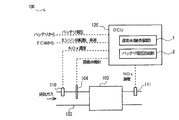
図1及び図2に示されるように、本発明に係るSCRシステム100は、エンジンEの排気管102に設けられたSCR装置103と、SCR装置103の上流側で尿素水を噴射するドージングバルブ104と、排気ガス中のNOx濃度を検出するNOxセンサ110,111と、NOxセンサ110,111で検出されたNOx濃度に応じて尿素水噴射を制御する尿素水噴射制御部1と、エンジン回転数Reがあらかじめ設定された下限値R1を超えており、かつ、車速Veがあらかじめ設定された下限値V1を超えているときに、バッテリ電圧Baを診断し、バッテリ電圧Baがあらかじめ設定された上限電圧B1以下であれば、適正電圧であると判定し、バッテリ電圧Baが上限電圧B1を超えていれば、適正電圧でないと判定するバッテリ電圧診断部2とを備える。
As shown in FIGS. 1 and 2, an
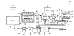
詳しくは、図2に示すように、SCRシステム100は、エンジンEの排気管102に設けられたSCR装置103と、SCR装置103の上流側(排気ガスの上流側)で尿素水を噴射するドージングバルブ(尿素噴射装置、ドージングモジュール)104と、尿素水を貯留する尿素タンク105と、尿素タンク105に貯留された尿素水をドージングバルブ104に供給するサプライモジュール106と、ドージングバルブ104やサプライモジュール106等を制御するDCU(Dosing Control Unit)126とを主に備える。
Specifically, as shown in FIG. 2, the
エンジンEの排気管102には、排気ガスの上流側から下流側にかけて、DOC(Diesel Oxidation Catalyst;酸化触媒)107、DPF(Diesel Particulate Filter)108、SCR装置103が順次配置される。DOC107は、エンジンEから排気される排気ガス中のNOを酸化してNO2とし、排気ガス中のNOとNO2の比率を制御してSCR装置103における脱硝効率を高めるためのものである。また、DPF108は、排気ガス中のPM(Particulate Matter)を捕集するためのものである。
In the
SCR装置103の上流側の排気管102には、ドージングバルブ104が設けられる。ドージングバルブ104は、高圧の尿素水が満たされたシリンダに噴口が設けられ、その噴口を塞ぐ弁体がプランジャに取り付けられた構造となっており、コイルに通電することによりプランジャを引き上げることで弁体を噴口から離間させて尿素水を噴射するようになっている。コイルへの通電を止めると、内部のバネ力によりプランジャが引き下げられて弁体が噴口を塞ぐので尿素水の噴射が停止される。
A
ドージングバルブ104の上流側の排気管102には、SCR装置103の入口における排気ガスの温度(SCR入口温度)を測定する排気温度センサ109が設けられる。また、SCR装置103の上流側(ここでは排気温度センサ109の上流側)には、SCR装置103の上流側でのNOx濃度を検出する上流側NOxセンサ110が設けられ、SCR装置103の下流側には、SCR装置103の下流側でのNOx濃度を検出する下流側NOxセンサ111が設けられる。
The
サプライモジュール106は、尿素水を圧送するSMポンプ112と、サプライモジュール106の温度(サプライモジュール106を流れる尿素水の温度)を測定するSM温度センサ113と、サプライモジュール106内における尿素水の圧力(SMポンプ112の吐出側の圧力)を測定する尿素水圧力センサ114と、尿素水の流路を切り替えることにより、尿素タンク105からの尿素水をドージングバルブ104に供給するか、あるいはドージングバルブ104内の尿素水を尿素タンク105に戻すかを切り替えるリバーティングバルブ115とを備えている。ここでは、リバーティングバルブ115がONのとき、尿素タンク105からの尿素水をドージングバルブ104に供給するようにし、リバーティングバルブ115がOFFのとき、ドージングバルブ104内の尿素水を尿素タンク105に戻すようにした。
The
リバーティングバルブ115が尿素水をドージングバルブ104に供給するように切り替えられている場合、サプライモジュール106は、そのSMポンプ112にて、尿素タンク105内の尿素水を送液ライン(サクションライン)116を通して吸い上げ、圧送ライン(プレッシャーライン)117を通してドージングバルブ104に供給するようにされ、余剰の尿素水を、回収ライン(バックライン)118を通して尿素タンク105に戻すようにされる。
When the reverting
尿素タンク105には、SCRセンサ119が設けられる。SCRセンサ119は、尿素タンク105内の尿素水の液面高さ(レベル)を測定するレベルセンサ120と、尿素タンク105内の尿素水の温度を測定する温度センサ121と、尿素タンク105内の尿素水の品質を測定する品質センサ122とを備えている。品質センサ122は、例えば、超音波の伝播速度や電気伝導度から、尿素水の濃度や尿素水に異種混合物が混合されているか否かを検出し、尿素タンク105内の尿素水の品質を検出するものである。 The urea tank 105 is provided with an SCR sensor 119. The SCR sensor 119 includes a level sensor 120 that measures the level (level) of urea water in the urea tank 105, a temperature sensor 121 that measures the temperature of urea water in the urea tank 105, and a sensor in the urea tank 105. And a quality sensor 122 for measuring the quality of the urea water. The quality sensor 122 detects the quality of the urea water in the urea tank 105 by detecting, for example, the concentration of urea water and whether or not a different mixture is mixed in the urea water from the propagation speed and electrical conductivity of the ultrasonic waves. To do.
尿素タンク105とサプライモジュール106には、エンジンEを冷却するための冷却水を循環する冷却ライン123が接続される。冷却ライン123は、尿素タンク105内を通り、冷却ライン123を流れる冷却水と尿素タンク105内の尿素水との間で熱交換するようにされる。同様に、冷却ライン123は、サプライモジュール106内を通り、冷却ライン123を流れる冷却水とサプライモジュール106内の尿素水との間で熱交換するようにされる。
A cooling line 123 for circulating cooling water for cooling the engine E is connected to the urea tank 105 and the
冷却ライン123には、尿素タンク105とサプライモジュール106に冷却水を供給するか否かを切り替えるタンクヒーターバルブ(クーラントバルブ)124が設けられる。なお、ドージングバルブ104にも冷却ライン123が接続されるが、ドージングバルブ104には、タンクヒーターバルブ124の開閉に拘わらず、冷却水が供給されるように構成されている。なお、図2では図を簡略化しており示されていないが、冷却ライン123は、尿素水が通る送液ライン116、圧送ライン117、回収ライン118に沿って配設される。
The cooling line 123 is provided with a tank heater valve (coolant valve) 124 for switching whether or not to supply cooling water to the urea tank 105 and the
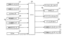
図3に、DCU126の入出力構成図を示す。
FIG. 3 shows an input / output configuration diagram of the
図3に示すように、DCU126には、上流側NOxセンサ110、下流側NOxセンサ111、SCRセンサ119(レベルセンサ120、温度センサ121、品質センサ122)、排気温度センサ109、サプライモジュール106のSM温度センサ113と尿素水圧力センサ114、およびエンジンEを制御するECM(Engine Control Module)125からの入力信号線が接続されている。ECM125からDCU126には、エンジン回転数、車速などのエンジンパラメータの信号が入力される。DCU126には、図示しないバッテリの電源ラインから電圧モニタ用の信号が入力される。
As shown in FIG. 3, the DCU 126 includes an
また、DCU126には、タンクヒーターバルブ124、サプライモジュール106のSMポンプ112とリバーティングバルブ115、ドージングバルブ104、上流側NOxセンサ110のヒータ、下流側NOxセンサ111のヒータ、への出力信号線が接続される。なお、DCU126と各部材との信号の入出力に関しては、個別の信号線を介した入出力、CAN(Controller Area Network)を介した入出力のどちらであってもよい。
The
DCU126は、ECM125からのエンジンパラメータの信号と、排気温度センサ109からの排気ガス温度とを基に、排気ガス中のNOxの量を推定すると共に、推定した排気ガス中のNOxの量を基にドージングバルブ104から噴射する尿素水量を決定するようにされ、さらに、ドージングバルブ104にて決定した尿素水量で噴射したとき、上流側NOxセンサ110の検出値に基づいてドージングバルブ104を制御して、ドージングバルブ104から噴射する尿素水量を調整するようにされる。
The
以下、本発明のSCRシステム100の動作を説明する。
Hereinafter, the operation of the
本発明のSCRシステム100では、キーオン時に、図4の手順が適宜な時間刻みで繰り返し実行される。
In the
図4に示されるように、ステップS41にて、バッテリ電圧診断部2は、エンジン回転数Reが下限値R1を超えているかどうか判定する。NOの場合、終わりとなる。YESの場合、エンジン回転数Reが下限値R1を超えていることになるので、ステップS42に進む。 As shown in FIG. 4, in step S41, the battery voltage diagnosis unit 2 determines whether the engine speed Re exceeds the lower limit value R1. If NO, it is the end. In the case of YES, the engine speed Re exceeds the lower limit value R1, so the process proceeds to step S42.
ステップS42にて、バッテリ電圧診断部2は、車速Veが下限値V1を超えているかどうか判定する。NOの場合、終わりとなる。YESの場合、車速Veが下限値V1を超えていることになるので、ステップS43に進む。 In step S42, battery voltage diagnostic unit 2 determines whether vehicle speed Ve exceeds lower limit value V1. If NO, it is the end. In the case of YES, the vehicle speed Ve exceeds the lower limit value V1, so the process proceeds to step S43.
ステップS43にて、バッテリ電圧診断部2は、バッテリ電圧Baが上限電圧B1以下かどうか判定する。YESの場合、ステップS44に進む。NOの場合、ステップS45に進む。 In step S43, the battery voltage diagnosis unit 2 determines whether the battery voltage Ba is equal to or lower than the upper limit voltage B1. If yes, go to step S44. If no, the process proceeds to step S45.
ステップS44では、バッテリ電圧Baが上限電圧B1以下であるから、適正電圧であると判定する。 In step S44, since the battery voltage Ba is equal to or lower than the upper limit voltage B1, it is determined that the voltage is appropriate.
ステップS45では、バッテリ電圧Baが上限電圧B1を超えているから、適正電圧でないと判定する。 In step S45, since the battery voltage Ba exceeds the upper limit voltage B1, it is determined that the voltage is not appropriate.
このように、バッテリ電圧診断部2は、エンジン回転数Reが下限値R1以下のときは、バッテリ電圧Baの高低について判定を行わない。これは、エンジン始動時にバッテリ電圧が低電圧であったためにバッテリを直列接続に繋ぎ替え、見かけ上、バッテリ電圧が高くなった場合を考慮し、エンジンが十分な回転数で回転するまで、判定を回避するものである。下限値R1は、実験により適宜な値を見いだして設定するのが好ましい。 Thus, when the engine speed Re is equal to or lower than the lower limit value R1, the battery voltage diagnosis unit 2 does not determine whether the battery voltage Ba is high or low. This is because the battery voltage was low when the engine was started, so the battery was connected in series connection, and the judgment was made until the engine was rotated at a sufficient number of revolutions, considering the case where the battery voltage was apparently increased. It is something to avoid. The lower limit R1 is preferably set by finding an appropriate value through experiments.
また、バッテリ電圧診断部2は、車速Veが下限値V1以下のときは、バッテリ電圧Baの高低について判定を行わない。これは、エンジンが十分な回転数で回転していてもバッテリが直列接続から並列接続に戻されていない場合を考慮し、車両が走行するようになるまで、判定を回避するものである。下限値V1は、実験により適宜な値を見いだして設定するのが好ましい。 Further, the battery voltage diagnosis unit 2 does not determine whether the battery voltage Ba is high or low when the vehicle speed Ve is equal to or lower than the lower limit value V1. This considers the case where the battery is not returned from the serial connection to the parallel connection even when the engine is rotating at a sufficient speed, and avoids the determination until the vehicle travels. The lower limit value V1 is preferably set by finding an appropriate value through experiments.
バッテリ電圧診断部2は、エンジン回転数Reが下限値R1を超えており、かつ、車速Veが下限値V1を超えているときに、バッテリ電圧Baを診断することになる。これは、エンジンが十分な回転数で回転しており、かつ、車両が走行しているので、直列接続は外されているはずであるからである。 The battery voltage diagnosis unit 2 diagnoses the battery voltage Ba when the engine speed Re exceeds the lower limit value R1 and the vehicle speed Ve exceeds the lower limit value V1. This is because the engine is rotating at a sufficient number of revolutions and the vehicle is running, so the series connection should be removed.
このとき、バッテリ電圧診断部2は、バッテリ電圧Baが上限電圧B1以下であれば、適正電圧であると判定する。上限電圧B1は、SCR制御に用いられるセンサやバルブに過電流が流れることがなく、センサやバルブが正常に作動してSCRシステムが正常に作動できる電圧とする。このように、バッテリ電圧診断部2がバッテリ電圧Baを適正電圧と判定した結果、尿素水噴射制御部1は、センサやバルブに故障を生じることなく、正しくNOx濃度を読み取り、正しく尿素水噴射を制御することが可能となる。 At this time, the battery voltage diagnosis unit 2 determines that the battery voltage Ba is an appropriate voltage if the battery voltage Ba is equal to or lower than the upper limit voltage B1. The upper limit voltage B1 is a voltage at which an overcurrent does not flow through a sensor or valve used for SCR control, and the sensor or valve operates normally and the SCR system can operate normally. As described above, as a result of the battery voltage diagnosis unit 2 determining that the battery voltage Ba is an appropriate voltage, the urea water injection control unit 1 correctly reads the NOx concentration without causing a failure in the sensor or the valve, and correctly performs the urea water injection. It becomes possible to control.
一方、バッテリ電圧診断部2は、バッテリ電圧Baが上限電圧B1を超えていれば、適正電圧でないと判定する。すなわち、バッテリ電圧Baが異常に高いことになる。この状態では、尿素水噴射制御部1が行うSCR制御に用いられるセンサやバルブに過電流が流れて故障が生じたり、センサやバルブが正常に作動せず、SCRシステム100が正常に作動しなくなる。そこで、SCRシステム100は、異常警告を行うことによって運転者に修理を促すことになる。
On the other hand, if the battery voltage Ba exceeds the upper limit voltage B1, the battery voltage diagnosis unit 2 determines that the voltage is not appropriate. That is, the battery voltage Ba is abnormally high. In this state, an overcurrent flows through a sensor or valve used in the SCR control performed by the urea water injection control unit 1 to cause a failure, or the sensor or valve does not operate normally, and the
以上説明したように、本発明のSCRシステム100によれば、エンジン回転数Reがあらかじめ設定された下限値R1を超えており、かつ、車速Veがあらかじめ設定された下限値V1を超えているときに、バッテリ電圧Baを診断し、バッテリ電圧Baがあらかじめ設定された上限電圧B1以下であれば、適正電圧であると判定し、バッテリ電圧Baが上限電圧B1を超えていれば、適正電圧でないと判定する。これにより、バッテリを直列接続にしてエンジン始動を行うときのバッテリ故障という判定がなくなる。
As described above, according to the
本実施形態では、バッテリ電圧診断部2は、バッテリ電圧Baが上限電圧B1を超えていれば、ただちに適正電圧でないと判定したが、バッテリ電圧Baが上限電圧B1を超えている時間Tmがあらかじめ設定された待ち時間T1未満では、判定を保留し、バッテリ電圧Baが上限電圧B1を超えている時間Tmが待ち時間T1以上になると、適正電圧でないと判定するようにしてもよい。 In the present embodiment, the battery voltage diagnosis unit 2 immediately determines that the battery voltage Ba is not an appropriate voltage if the battery voltage Ba exceeds the upper limit voltage B1, but the time Tm during which the battery voltage Ba exceeds the upper limit voltage B1 is set in advance. If the waiting time T1 is less than the waiting time T1, the determination may be suspended, and if the time Tm during which the battery voltage Ba exceeds the upper limit voltage B1 becomes equal to or longer than the waiting time T1, it may be determined that the voltage is not appropriate.
1 尿素水噴射制御部
2 バッテリ電圧診断部
100 SCRシステム
104 ドージングバルブ
110,111 NOxセンサ
DESCRIPTION OF SYMBOLS 1 Urea water injection control part 2 Battery voltage
Claims (1)
前記選択還元触媒装置の上流側で尿素水を噴射するドージングバルブと、
排気ガス中のNOx濃度を検出するNOxセンサと、
前記NOxセンサで検出されたNOx濃度に応じて尿素水噴射を制御する尿素水噴射制御部と、
エンジン回転数があらかじめ設定された下限値を超えており、かつ、車速があらかじめ設定された下限値を超えているときに、ジャンパスタート中でないとしてバッテリ電圧を診断し、バッテリ電圧が上限電圧以下であれば、適正電圧であると判定し、バッテリ電圧が前記上限電圧を超えていれば、適正電圧でないと判定するバッテリ電圧診断部と、
を備えるSCRシステムであって、
前記上限電圧は、前記SCRシステムが正常に作動できる電圧に設定されていることを特徴とするSCRシステム。 A selective catalytic reduction device provided in the exhaust pipe of the engine;
A dosing valve for injecting urea water upstream of the selective reduction catalyst device;
A NOx sensor for detecting the NOx concentration in the exhaust gas;
A urea water injection control unit that controls urea water injection according to the NOx concentration detected by the NOx sensor;
Engine speed exceeds the preset lower limit, and, when the vehicle speed exceeds the preset lower limit value to diagnose the battery voltage as not being jumper start, the battery voltage is below the upper limit voltage if, it is determined to be proper voltage, if the battery voltage exceeds the upper limit voltage, and the determining the battery voltage diagnosis section improper voltage,
A SCR system Ru with a,
The upper limit voltage is set to a voltage at which the SCR system can operate normally .
Priority Applications (1)
| Application Number | Priority Date | Filing Date | Title |
|---|---|---|---|
| JP2010113371A JP5589552B2 (en) | 2010-05-17 | 2010-05-17 | SCR system |
Applications Claiming Priority (1)
| Application Number | Priority Date | Filing Date | Title |
|---|---|---|---|
| JP2010113371A JP5589552B2 (en) | 2010-05-17 | 2010-05-17 | SCR system |
Publications (2)
| Publication Number | Publication Date |
|---|---|
| JP2011241720A JP2011241720A (en) | 2011-12-01 |
| JP5589552B2 true JP5589552B2 (en) | 2014-09-17 |
Family
ID=45408644
Family Applications (1)
| Application Number | Title | Priority Date | Filing Date |
|---|---|---|---|
| JP2010113371A Expired - Fee Related JP5589552B2 (en) | 2010-05-17 | 2010-05-17 | SCR system |
Country Status (1)
| Country | Link |
|---|---|
| JP (1) | JP5589552B2 (en) |
Family Cites Families (5)
| Publication number | Priority date | Publication date | Assignee | Title |
|---|---|---|---|---|
| JP2661929B2 (en) * | 1987-12-28 | 1997-10-08 | アイシン・エィ・ダブリュ株式会社 | Fail-safe control device for electronically controlled automatic transmission |
| JPH01208213A (en) * | 1988-02-13 | 1989-08-22 | Nippon Denso Co Ltd | Damping force control device of shock absorber |
| JP4271124B2 (en) * | 2004-10-21 | 2009-06-03 | 日産ディーゼル工業株式会社 | Vehicle idle stop device |
| JP2009145219A (en) * | 2007-12-14 | 2009-07-02 | Denso Corp | NOx SENSOR DIAGNOSING SYSTEM FOR INTERNAL COMBUSTION ENGINE |
| JP5258085B2 (en) * | 2008-02-08 | 2013-08-07 | ボッシュ株式会社 | NOX sensor rationality diagnostic device, rationality diagnostic method, and exhaust purification device for internal combustion engine |
-
2010
- 2010-05-17 JP JP2010113371A patent/JP5589552B2/en not_active Expired - Fee Related
Also Published As
| Publication number | Publication date |
|---|---|
| JP2011241720A (en) | 2011-12-01 |
Similar Documents
| Publication | Publication Date | Title |
|---|---|---|
| JP5789925B2 (en) | NOx sensor diagnostic device and SCR system | |
| JP5786280B2 (en) | Validity diagnosis system for urea water temperature sensor | |
| CN101918687B (en) | Fault diagnosis apparatus for oxidation catalyst, method of fault diagnosis for oxidation catalyst, and exhaust purification apparatus of internal combustion engine | |
| CN102947562B (en) | Selective Catalytic Reduction Thaw Control System | |
| JP5471831B2 (en) | SCR system | |
| JP5533235B2 (en) | NOx sensor diagnostic device and SCR system | |
| JP5633190B2 (en) | Return control system | |
| JP5482446B2 (en) | SCR system | |
| JP5678475B2 (en) | SCR system | |
| JP5573352B2 (en) | Validity diagnosis system for urea water temperature sensor | |
| US9441521B2 (en) | Method for removing foreign matter from a selective reduction catalyst system | |
| JP5516072B2 (en) | SCR system | |
| JP5471833B2 (en) | SCR system | |
| JP5471832B2 (en) | SCR system | |
| JP5589552B2 (en) | SCR system | |
| JP5589553B2 (en) | SCR system | |
| JP2011241722A (en) | Exhaust emission control system | |
| JP5617342B2 (en) | SCR system |
Legal Events
| Date | Code | Title | Description |
|---|---|---|---|
| A621 | Written request for application examination |
Free format text: JAPANESE INTERMEDIATE CODE: A621 Effective date: 20130405 |
|
| A977 | Report on retrieval |
Free format text: JAPANESE INTERMEDIATE CODE: A971007 Effective date: 20131129 |
|
| A131 | Notification of reasons for refusal |
Free format text: JAPANESE INTERMEDIATE CODE: A131 Effective date: 20131203 |
|
| A521 | Request for written amendment filed |
Free format text: JAPANESE INTERMEDIATE CODE: A523 Effective date: 20140124 |
|
| TRDD | Decision of grant or rejection written | ||
| A01 | Written decision to grant a patent or to grant a registration (utility model) |
Free format text: JAPANESE INTERMEDIATE CODE: A01 Effective date: 20140701 |
|
| A61 | First payment of annual fees (during grant procedure) |
Free format text: JAPANESE INTERMEDIATE CODE: A61 Effective date: 20140714 |
|
| R150 | Certificate of patent or registration of utility model |
Ref document number: 5589552 Country of ref document: JP Free format text: JAPANESE INTERMEDIATE CODE: R150 |
|
| LAPS | Cancellation because of no payment of annual fees |


