JP5589544B2 - Image processing apparatus, image processing method, program, and recording medium - Google Patents
Image processing apparatus, image processing method, program, and recording medium Download PDFInfo
- Publication number
- JP5589544B2 JP5589544B2 JP2010109636A JP2010109636A JP5589544B2 JP 5589544 B2 JP5589544 B2 JP 5589544B2 JP 2010109636 A JP2010109636 A JP 2010109636A JP 2010109636 A JP2010109636 A JP 2010109636A JP 5589544 B2 JP5589544 B2 JP 5589544B2
- Authority
- JP
- Japan
- Prior art keywords
- color
- colors
- unit
- image data
- image processing
- Prior art date
- Legal status (The legal status is an assumption and is not a legal conclusion. Google has not performed a legal analysis and makes no representation as to the accuracy of the status listed.)
- Active
Links
Images


Classifications
-
- G—PHYSICS
- G09—EDUCATION; CRYPTOGRAPHY; DISPLAY; ADVERTISING; SEALS
- G09G—ARRANGEMENTS OR CIRCUITS FOR CONTROL OF INDICATING DEVICES USING STATIC MEANS TO PRESENT VARIABLE INFORMATION
- G09G5/00—Control arrangements or circuits for visual indicators common to cathode-ray tube indicators and other visual indicators
- G09G5/02—Control arrangements or circuits for visual indicators common to cathode-ray tube indicators and other visual indicators characterised by the way in which colour is displayed
- G09G5/028—Circuits for converting colour display signals into monochrome display signals
Landscapes
- Engineering & Computer Science (AREA)
- Physics & Mathematics (AREA)
- Computer Hardware Design (AREA)
- General Physics & Mathematics (AREA)
- Theoretical Computer Science (AREA)
- Image Processing (AREA)
- Color Image Communication Systems (AREA)
- Facsimile Image Signal Circuits (AREA)
Description
本発明は、画像処理装置、画像処理方法、プログラムおよび記録媒体に関する。 The present invention relates to an image processing apparatus, an image processing method, a program, and a recording medium.
近年、カラー画像を表示または印刷するといったカラー画像出力技術が発達したことにより、個人や企業が作成する文書には、様々な色付き文字やカラー画像が使用されるようになった。このような文書では、注意を促す表記やグラフのグループ分けのために、色付き文字や複数の色による塗り分けを行うといった、色そのものに重要な情報を持たせている場合が多い。そのため、これらの文書の内容を正しく理解するためには、文字や画像を認識する能力に加え、文書に用いられている色の違いを判別する能力も求められる。 In recent years, with the development of color image output technology for displaying or printing color images, various colored characters and color images have been used for documents created by individuals and companies. In such a document, in many cases, important information is given to the color itself, such as coloring with a colored character or a plurality of colors for notation and graph grouping. Therefore, in order to correctly understand the contents of these documents, in addition to the ability to recognize characters and images, the ability to discriminate between the colors used in the documents is also required.
このような様々な色を用いた文書は、一般的な色覚を持った人々に対しては情報を理解させやすいが、一般の色覚と異なる色覚特性を持った人々にとっては必ずしもそうではない。人間の色覚に関する生理的、医学的研究によると、これまで、色覚特性には、赤と緑が判別しにくいまたは判別できない赤緑色盲や、その他に黄青色盲および全色盲などの型が存在することが知られている。最近では、CUDO(NPO法人 カラーユニバーサルデザイン機構)が、色覚が正常または異常という線引きではなく、C型(Commonの頭文字)などの色覚の型名を用いて、C型色覚の人を一般色覚、それ以外の色の認識に関して弱い部分のある人を色弱者と呼ぶことを提唱している。色覚の型としては、C型のほかに、P型(Protanope)の強度・弱度(赤緑色盲又は色弱に相当)、D型(Deuteranope)の強度・弱度(赤緑色盲又は色弱に相当)、T型(Tritanope)(黄青色盲に相当)、および、A型(Achromat)(全色盲に相当)が存在する。 Such a document using various colors makes it easy for people with general color vision to understand information, but it is not necessarily so for people with color vision characteristics different from general color vision. Physiological and medical studies on human color vision have shown that color vision characteristics include red-green blindness that is difficult or impossible to distinguish between red and green, and other types such as yellow-blue blindness and all-color blindness. It is known. Recently, CUDO (NPO Color Universal Design Organization) is using color vision type names such as C type (Common acronym) instead of the line drawing that color vision is normal or abnormal. , He advocates calling people who have weak parts of color recognition as color weak. As color vision type, in addition to C type, P type (Protanope) intensity / weakness (equivalent to red-green blindness or color weakness), D type (Deuteranope) intensity / weakness (equivalent to red-green blindness or color weakness) ), T type (Tritanope) (corresponding to yellow-blue blindness), and A type (Achromat) (corresponding to all color blindness).
従来は、このような様々な色覚特性を持った人が色を判別しやすいようにするための文書作成の負荷が非常に大きくなると同時に、デザインの自由度が制限される場合があった。例えば、一般色覚者がプレゼンテーション用の電子文書を作成し、それをカラー印刷して配布し、スクリーンへ電子文書を投影してプレゼンテーションを行うようなごく一般的なシチュエーションを想定する。この場合、例えばグラフを作成する一般的なオフィスアプリケーションソフトでは、各要素が自動で配色されるため、ユーザーが1要素ずつ色を指定しなおさなければならない場合があった。 Conventionally, a document creation load for making it easy for a person having such various color vision characteristics to distinguish colors has become very large, and at the same time, the degree of freedom in design has been limited. For example, a very general situation is assumed in which an ordinary color vision person creates an electronic document for presentation, distributes it by color printing, and projects the electronic document on a screen for presentation. In this case, for example, in general office application software for creating a graph, since each element is automatically colored, there is a case where the user has to respecify the color element by element.
また、一般的に、カラープリンタのような印刷装置、および、スクリーン上へ画像を投影するプロジェクタのように異なる画像出力装置では、それぞれ再現できる色の範囲が異なる。このため、印刷物上で色の違いが分かりやすいように配色をしても、投影画像では、色が違ってしまい、色の判別性が改善されない場合があった。 In general, different color output ranges are different between different printing apparatuses such as a color printer and different image output apparatuses such as a projector that projects an image on a screen. For this reason, even if the color arrangement is made so that the difference in color is easily understood on the printed matter, the color is different in the projected image, and the color discrimination may not be improved.
このような問題に対して、文書を作成する一般色覚者に対して、色弱者が混同しやすい色を選択できないようにすることで、文書作成時に混同しにくい色を選びやすくする色見本選択装置が提案されている。また、色弱者の見え方を模擬した画像を提示することで、一般色覚者に対し、色弱者にとって判別しにくい部分が分かるようにする表示システムが提案されている。 In order to solve this problem, a color sample selection device that makes it easy for color-blind people who create documents to select colors that are not easily confused when creating documents by preventing color-blind people from selecting colors that are easily confused. Has been proposed. In addition, a display system has been proposed that presents an image that simulates the appearance of a color weak person so that a general color sense person can recognize a portion that is difficult for the color weak person to distinguish.
例えば、特許文献1では、色弱者が判別しにくい色の組み合わせを使わせないようにする目的で、文書やデザインに使う色を選択すると、その色と色弱者が混同しやすい色を選択できないようにする色見本選択装置が開示されている。また、特許文献2では、一般色覚者に対して色弱者の色の判別のしにくさを認識させる目的で、色弱者の色の見え方を模擬した画像を提示する表示システムが開示されている。
For example, in
しかしながら、特許文献1および2のような方法でも、色弱者が判別できるか否かを一般色覚者が判断しづらい場合や、文書作成の負荷が改善できない場合があるという問題があった。例えば、特許文献2のような表示システムでは、色覚シミュレーション画像を提示する。しかし、シミュレーションツールによって色味が異なることや、一般色覚者にも色覚特性に個人差が存在することが知られている。このため、色覚シミュレーションの結果で、少し色が違っていた場合、その色の違いが色弱者にとって判別しにくいのかどうかを一般色覚者が判断するのが困難となる場合がある。また、判別しにくいと判断した場合、色弱者に判別しにくい色の使用を控えたり、別の色に置き換えるという、デザイン上の制限や、配色を変更する手間が発生するという問題が生じる。
However, even the methods disclosed in
本発明は、上記に鑑みてなされたものであって、文書作成時の負荷の増大およびデザインの自由度の制限を回避できる画像処理装置、画像処理方法、プログラムおよび記録媒体を提供することを目的とする。 The present invention has been made in view of the above, and an object of the present invention is to provide an image processing apparatus, an image processing method, a program, and a recording medium that can avoid an increase in load at the time of document creation and a restriction on the degree of freedom of design. And
上述した課題を解決し、目的を達成するために、本発明は、入力画像データから、塗りつぶしに用いられている使用色を抽出する色抽出部と、前記使用色で塗りつぶされた領域の面積を算出する面積評価部と、前記面積に基づいて、領域の識別性を評価する識別性評価値を算出する識別性評価部と、前記識別性評価値が所定値より小さい場合に、前記入力画像データの対応する領域の識別性を向上させる色調整を行う色調整部と、色調整後の前記入力画像データを画像形成に用いる画像形成用データに変換する色変換部と、前記画像形成用データによる画像形成を制御する制御部と、を備え、前記色変換部は、前記入力画像データの色空間に含まれる色のうち、色弱者が相互に判別することが困難な色として予め定められた複数の色それぞれを、前記画像形成用データの色空間の同一色に変換すること、を特徴とする。 In order to solve the above-described problems and achieve the object, the present invention provides a color extraction unit that extracts a used color used for filling from input image data, and an area of the region filled with the used color. An area evaluation unit to calculate, a discriminability evaluation unit to calculate a discriminability evaluation value for evaluating the discriminability of a region based on the area, and the input image data when the discriminability evaluation value is smaller than a predetermined value A color adjustment unit that performs color adjustment to improve the identification of the corresponding region of the image, a color conversion unit that converts the input image data after color adjustment into image formation data used for image formation, and the image formation data. A control unit that controls image formation, and the color conversion unit includes a plurality of colors that are determined in advance as colors that are difficult for color-weak persons to distinguish from each other in the color space of the input image data. Each color , It is converted to the same color of the color space of the image forming data, wherein.
また、本発明は、入力画像データから、塗りつぶしに用いられている使用色を抽出する色抽出ステップと、前記使用色で塗りつぶされた領域の面積を算出する面積評価ステップと、前記面積に基づいて、領域の識別性を評価する識別性評価値を算出する識別性評価ステップと、前記識別性評価値が所定値より小さい場合に、前記入力画像データの対応する領域の識別性を向上させる色調整を行う色調整ステップと、色調整後の前記入力画像データを画像形成に用いる画像形成用データに変換する色変換ステップと、前記画像形成用データによる画像形成を制御する制御ステップと、を含み、前記色変換ステップは、前記入力画像データの色空間に含まれる色のうち、色弱者が相互に判別することが困難な色として予め定められた複数の色それぞれを、前記画像形成用データの色空間の同一色に変換すること、を特徴とする画像処理方法である。 Further, the present invention is based on the color extraction step of extracting the used color used for filling from the input image data, the area evaluation step of calculating the area of the region filled with the used color, and the area A discriminability evaluation step for calculating a discriminability evaluation value for evaluating the discriminability of the region; and color adjustment for improving the discriminability of the corresponding region of the input image data when the discriminability evaluation value is smaller than a predetermined value. A color adjustment step for performing color adjustment, a color conversion step for converting the input image data after color adjustment into image formation data used for image formation, and a control step for controlling image formation by the image formation data, The color conversion step includes a plurality of colors that are determined in advance as colors that are difficult for the color weak to distinguish from each other in the color space of the input image data. Les and be converted to the same color of the color space of the image forming data is an image processing method according to claim.
また、本発明は、上記画像処理方法をコンピュータに実現させるためのプログラムである。 The present invention is also a program for causing a computer to realize the image processing method.
また、本発明は、上記画像処理方法をコンピュータに実現させるためのプログラムを記録したコンピュータ読み取り可能な記録媒体である。 The present invention is also a computer-readable recording medium that records a program for causing a computer to implement the image processing method.
本発明によれば、文書作成時の負荷の増大およびデザインの自由度の制限を回避できるという効果を奏する。 According to the present invention, it is possible to avoid an increase in load at the time of document creation and a restriction on the degree of freedom of design.
以下に添付図面を参照して、この発明にかかる画像処理装置、画像処理方法、プログラムおよび記録媒体の一実施の形態を詳細に説明する。 Exemplary embodiments of an image processing apparatus, an image processing method, a program, and a recording medium according to the present invention will be explained below in detail with reference to the accompanying drawings.
(第1の実施の形態)
第1の実施の形態の画像処理装置は、印刷などによる画像出力時に、入力画像データ中の色弱者が混同しやすい色を、同色に置き換えて出力する。第1の実施の形態は、例えばオフィスアプリケーションなどでグラフに使われる配色が予め判明しているケースを想定する。そして、混同色同士を同じ色に変換するLUT(Look Up Table)を予め用意し、このLUTを用いて混同色を同一色に変換する。
(First embodiment)
The image processing apparatus according to the first embodiment replaces a color that is easily confused by a color weak person in input image data with the same color when outputting an image by printing or the like. The first embodiment assumes a case where the color scheme used for a graph in an office application or the like is known in advance. Then, an LUT (Look Up Table) for converting the confusion colors into the same color is prepared in advance, and the confusion colors are converted into the same color using the LUT.
また、第1の実施の形態では、同色に置換した部分については口頭説明による情報補償を促す通知を行う。これにより、プレゼンテーション等を行う文書作成者の文書作成時の負荷を増大させないと同時に、デザインの自由度を制限しないようにし、作成した文書を利用したプレゼンテーション時には、口頭説明などの視覚情報以外の手段による情報補償をしやすくすることができる。 Further, in the first embodiment, notification for prompting information compensation by oral explanation is performed for the portion replaced with the same color. This will not increase the load of the document creator who will give a presentation, etc., while at the same time not limiting the degree of freedom of design, means other than visual information such as oral explanation at the time of presentation using the created document This makes it easy to compensate information.
なお、コミュニケーションによる情報補償については、直接指し棒などで指し示し、コミュニケーションでカバーすることで、プレゼンターの意図は伝わりやすくなることが、非特許文献1に記載されている(「バリアフリーのまとめと、そのほかの注意点」参照)。
In addition, as for information compensation by communication, it is described in
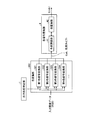
図1は、第1の実施の形態にかかる画像処理装置100の構成例を示すブロック図である。画像処理装置100は、例えば、MFP(Multi Function Peripheral)、プリンタ、スキャナ装置、ファクシミリ装置等の画像形成装置として実現できる。画像処理装置100は、入力された画像データ(入力画像データ)を変換して出力する装置であれば、一般的なパーソナル・コンピュータなどのその他のあらゆる装置に適用できる。
FIG. 1 is a block diagram illustrating a configuration example of an
図1に示すように、画像処理装置100は、出力形態指定部1と、色変換部2と、画像形成制御部3と、画像形成部6とを備えている。
As shown in FIG. 1, the
出力形態指定部1は、画像の出力形態(印刷モード)の指定を受け付ける。出力形態指定部1は、例えば、画像処理装置100に備えられた操作部(図示せず)や、画像処理装置100にネットワークなどにより接続されたコンピュータの表示装置およびマウスなどの入力装置などを用いたユーザーによる指定を受け付ける。印刷モードとしては、例えば、配色警告印刷を行う配色警告印刷モード、および通常の印刷を行う一般文書モードなどが指定できる。配色警告印刷モードとは、色弱者が混同しやすい色を同色に置換して印刷するモードを表す。出力形態指定部1は、例えば、配色警告印刷モードか否かを表す情報を含む印刷モード情報を色変換部2および画像形成制御部3に送出する。
The output
また、出力形態指定部1は、配色警告印刷モードが指定された場合、色弱者が相互に判別することが困難な色が同一色に変換される旨を通知する通知部として機能する。例えば、出力形態指定部1は、表示装置等に、色の違いの分からない場所については、指し示して口頭での説明を促す旨を表すメッセージを表示する。なお、通知方法はこれに限られるものではなく、紙媒体へのメッセージの印刷など、その他の方法を適用してもよい。
The output
色変換部2は、指定された印刷モードに応じて、予め用意されている変換テーブルを補間して、入力画像データを画像形成に用いるデータ(画像形成用データ)に変換する。入力画像データは、一般的にはRGB色空間で表される。画像形成用データは、一般的にはCMY(K)色空間で表される。ただし、画像形成用データを印刷する代わりに、コンピュータの表示装置上に画像形成用データを提示する場合にはRGB色空間で表される。
The
画像形成制御部3は、指定された印刷モードに応じて、色変換部2により変換された画像形成用データを集約して印刷するように、または、両面印刷するように画像形成部6による画像の形成を制御する。
The image forming
画像形成部6は、画像形成制御部3による制御に応じ、色変換部2から送られてきた画像形成用データに基づき、紙や表示装置などの媒体へ画像を形成する。
The
図2は、第1の実施の形態の色変換部2の構成例を示すブロック図である。図2に示すように、色変換部2は、第1色信号変換部21と、第2色信号変換部22と、第3色信号変換部23と、第4色信号変換部24とを備えている。
FIG. 2 is a block diagram illustrating a configuration example of the
第1色信号変換部21、第2色信号変換部22、第3色信号変換部23、および第4色信号変換部24は、配色警告印刷モードが指定されると、入力画像データを予め用意された各色覚特性などに応じたそれぞれ異なる変換テーブル(詳細は後述)を用いて画像形成用データに変換し、変換後のデータを画像形成部6へ送る。
The first color
図3は、変換テーブルについて説明する図である。色変換部2は、図3に示すような変換テーブルを補間することにより、入力画像データを画像形成用データに変換する。
FIG. 3 is a diagram for explaining the conversion table. The
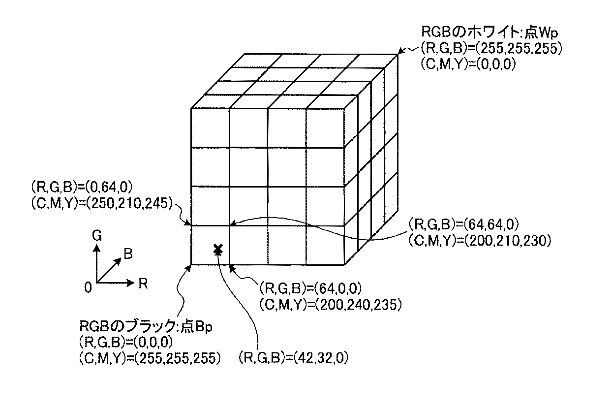
図3の変換テーブルは、入力画像データのRGB空間(RGBは0〜255の値を取る)を各成分4分割(64刻み)の格子点で区切った例である。各格子点には、入力画像データのRGB値に対応した、画像形成用データのCMY値が割り当てられている。例えば、図3中の(R,G,B)=(42,32,0)というRGB値を持つ入力画像データを画像形成用データに変換する場合、(R,G,B)=(0,0,0)(64,0,0)(0,64,0)(64,64,0)という4点に対応するCMY値を補間(重み付け平均)して、入力画像データに対応するCMY値を求める。この例では、入力画像データのB成分が0であるため、実質4点での補間となるが、一般にはB成分が存在するため、8点による補間となる。 The conversion table of FIG. 3 is an example in which the RGB space of input image data (RGB takes a value of 0 to 255) is divided by the grid points of each component divided into four (64 steps). Each grid point is assigned a CMY value of image forming data corresponding to the RGB value of the input image data. For example, when converting input image data having RGB values of (R, G, B) = (42, 32, 0) in FIG. 3 into image forming data, (R, G, B) = (0, 0, 0) (64, 0, 0) (0, 64, 0) (64, 64, 0) corresponding CMY values corresponding to input image data are interpolated (weighted average). Ask for. In this example, since the B component of the input image data is 0, the interpolation is substantially performed at 4 points. However, since the B component is generally present, the interpolation is performed at 8 points.
図4は、変換テーブルの生成方法について説明する図である。図4の横軸および縦軸は、それぞれCIELAB色空間のb*軸およびL*軸である。図4の入力画像データの色空間の定義範囲とは、入力画像データが取り得る色の範囲であり、一般的には、液晶ディスプレイなどの色再現範囲(例えばsRGB色空間)に相当する。また、出力装置の色再現範囲とは、MFPやプリンタなどの、紙媒体へ印刷する出力装置の色再現範囲である。一般的には、出力装置の色再現範囲より入力画像データの色空間の定義範囲の方が広い。 FIG. 4 is a diagram illustrating a conversion table generation method. The horizontal and vertical axes in FIG. 4 are the b * axis and L * axis of the CIELAB color space, respectively. The definition range of the color space of the input image data in FIG. 4 is a range of colors that can be taken by the input image data, and generally corresponds to a color reproduction range (for example, sRGB color space) of a liquid crystal display or the like. The color reproduction range of the output device is a color reproduction range of an output device that prints on a paper medium such as an MFP or a printer. In general, the definition range of the color space of the input image data is wider than the color reproduction range of the output device.
色変換部2は、入力画像データの色空間を図3に示したような格子点で分割し、各格子点のRGB値を、以下の(1)式〜(3)式によりXYZ三刺激値へ変換する。
色変換部2は、さらに、CIELAB色空間の定義に従い、XYZ三刺激値をL*a*b*値へ変換する。この時点では、入力画像データの色空間の定義範囲の方が出力装置の色再現範囲よりも広い。このため、出力装置の色再現範囲(予め多数のCMYの組合せに対応した色見本を出力し、測色するなどにより求めておく)へマッピングする。例えば、色差が最小となる方向にマッピングを行う。図4中の入力画像データの空間の格子点は、このようなマッピングを行った後の格子点を模式的に表している。
The
以下に、色変換部2に含まれる信号変換部(第1色信号変換部21、第2色信号変換部22、第3色信号変換部23、第4色信号変換部24)ごとの変換テーブルの生成方法について説明する。なお、第1色信号変換部21、第2色信号変換部22、第3色信号変換部23、および第4色信号変換部24の変換テーブルは、それぞれ一般色覚者(C型色覚)、P型色覚、D型色覚、およびT型色覚の色覚特性に応じた変換テーブルに相当する。
Below, the conversion table for each signal conversion unit (first color
(1)第1色信号変換部21の変換テーブルの生成方法
前述のマッピング後の各格子点のL*a*b*値に対し、色差が最小となる出力装置の画像形成用のCMY値を求める。これは、例えば、CMYを様々に組み合わせた色見本を出力・測色しておき、最も近い物を選んでも良いし、少数の色見本を出力・測色し、CMY値から出力されるL*a*b*値を予測するようなモデルを構築し、そのモデルに基づき最も色差の小さくなるCMY値を求めても良い。
(1) Generation Method of Conversion Table of First Color
以上の処理により、入力画像データのRGB値と出力装置の画像形成用のCMY値とを対応づけたテーブルが得られる。このテーブルを第1色信号変換部21の変換テーブルとする。
With the above processing, a table in which the RGB values of the input image data are associated with the CMY values for image formation of the output device is obtained. This table is used as the conversion table of the first color
なお、グラフなどの配色によっては、一般色覚者であっても、個人差により色を判別しにくい場合もある。このため、色弱者が判別しにくい色を同色に置き換えるのと同様の変換テーブルを生成するようにしても良い。その場合は、判別性評価式としてCIEのΔEabやΔE94色差式で色同士の色差を評価し、色差が所定値(例えば、同系色で色を明確に判別できる色差の目安とされる13程度)以下か否かで評価すれば良い。 Depending on the color scheme of the graph or the like, it may be difficult for a general color senser to determine the color due to individual differences. For this reason, a conversion table similar to replacing a color that is difficult for a color weak person with the same color may be generated. In that case, the color difference between colors is evaluated by the CIE ΔEab or ΔE94 color difference formula as a discriminability evaluation formula, and the color difference is a predetermined value (for example, about 13 which is a standard of color difference that can clearly discriminate colors with similar colors). What is necessary is just to evaluate by following or not.
(2)第2色信号変換部22の変換テーブルの生成方法(P型色覚を強調的に模擬)
前述のマッピング後の各格子点のL*a*b*値を、CIELAB色空間の定義式の逆計算により、XYZ三刺激値へ戻す。さらに、以下の(4)式により、錐体応答空間のLMS値へ変換する。さらに、以下の(5)式により、P型色覚者の錐体応答を模擬する信号へ変換する。そして、以下の(6)式によりXYZ三刺激値へ逆変換する。また、CIELAB色空間の定義に従い、XYZ三刺激値をL*a*b*値へ変換する。
The L * a * b * value of each lattice point after the above mapping is returned to the XYZ tristimulus value by inverse calculation of the definition formula of the CIELAB color space. Furthermore, it converts into the LMS value of a cone response space by the following (4) Formula. Furthermore, it converts into the signal which simulates the cone response of a P-type color vision person by the following (5) Formula. And it reverse-converts into an XYZ tristimulus value by the following (6) Formula. Further, according to the definition of the CIELAB color space, the XYZ tristimulus values are converted into L * a * b * values.
この結果算出されたL*a*b*値は、マッピング後の入力画像データの色空間の格子点の色をP型色覚者が見た場合の知覚量を模擬したものである。このP型色覚者の知覚量を模擬したL*a*b*値に対し、前述と同様に、色差最小となるCMY値を算出し、変換テーブルとする。ただし、この変換テーブルの一部の格子点上のCMY値を以下のように変更を加える。 The L * a * b * value calculated as a result is a simulation of the perception amount when the P-type color vision person sees the color of the grid point in the color space of the input image data after mapping. For the L * a * b * value that simulates the perception amount of the P-type color vision person, the CMY value that minimizes the color difference is calculated and used as the conversion table. However, the CMY values on some lattice points of this conversion table are changed as follows.
まず、一般的に、オフィスアプリケーション(表計算ソフト)などで作成される文書では、グラフに使われる配色は、予め決められた色が要素数に応じて順に割り当てられる。また、色文字などでも、カラーパレットにある数色を使って作成されるのが一般的である。 First, in general, in a document created by an office application (spreadsheet software) or the like, a predetermined color is sequentially assigned to a color scheme used for a graph according to the number of elements. Also, color characters are generally created using several colors in the color palette.
広く用いられているオフィスアプリケーションの配色の上位色を抽出し、上記P型色覚者の知覚量を模擬したL*a*b*値へ変換したテーブル(RGB to Lab(P型))を用い、前記上位色のRGB値に対するL*a*b*値を補間により求める。図4の四角記号のプロット(図4では6色)が、このような補間により求められたL*a*b*値を表している。 Using a table (RGB to Lab (P type)) that extracts the upper color of the color scheme of the widely used office application and converts it into L * a * b * values that simulate the perception amount of the P-type color sense person, L * a * b * values for the RGB values of the upper color are obtained by interpolation. The square symbol plots (six colors in FIG. 4) in FIG. 4 represent the L * a * b * values obtained by such interpolation.
これらの色同士の全ての色の組合せについて、以下の(7)式により判別性のスコアを算出する。(7)式は、色の判別性に関する主観評価実験の結果に加え、さらに入力画像データの色空間の黒色点と出力装置の黒色点との明度差kを考慮して求められる。
明度差kの値は、図4の出力装置の色再現範囲と入力画像データの色空間の定義範囲のそれぞれの黒色点の明度差に相当する値を用いる。前述の通り、出力装置の色再現範囲へのマッピングを行う際、はみ出した格子点を再現範囲表面に貼り付ける場合や、色空間全体を縮小して色再現範囲を一致させる場合などが考えられるが、通常、マッピングによる明度差は最大でもそれぞれの黒色点同士の明度差となる。 As the value of the brightness difference k, a value corresponding to the brightness difference of each black point in the color reproduction range of the output device of FIG. 4 and the defined range of the color space of the input image data is used. As described above, when mapping to the color gamut of the output device, there are cases where pasted grid points are pasted on the surface of the gamut, or when the entire color space is reduced to match the color gamut. Normally, the brightness difference due to mapping is at most the brightness difference between the black points.
一方、彩度方向のマッピングの影響も存在するが、(7)式のΔL*とΔb*の係数に現れているように、色の判別性には明度差が大きく寄与する。このため、本実施の形態では、黒色点同士の明度差程度のずれが生じることを前提に色の判別性を評価する。これにより、入力画像データの色空間(プロジェクタで投影する色空間など)と出力装置の色再現範囲の違いによって、実際に判別しにくい色の組合せと、本実施の形態の方法により同色に置き換える色の組合せとに相違が生じることを抑制できる。 On the other hand, although there is an influence of the mapping in the saturation direction, as shown in the coefficients of ΔL * and Δb * in the equation (7), the brightness difference greatly contributes to the color discrimination. For this reason, in this embodiment, the color discriminability is evaluated on the premise that a deviation of about the brightness difference between black points occurs. As a result, a combination of colors that are difficult to distinguish due to the difference in the color space of the input image data (such as the color space projected by the projector) and the color reproduction range of the output device, and the color that is replaced with the same color by the method of the present embodiment It can suppress that a difference arises with the combination of.
(7)式の(Dist.)が3未満の色の組合せが存在した場合、その色の補間計算に用いられる格子点に対応したCMY値を、それら格子点の平均値やCMY値の合計が最も少ないものに統一するように値を置換する。図4の例では、右上の2色の場合、○の6格子点が補間計算に用いられる格子点に相当する。左上の2色の場合は×の7格子点が補間計算に用いられる格子点に相当する。ただし、双方とも、実際にはa*方向の成分も存在する3次元空間であるため、さらに補間に使われる格子点数は増える。 (7) When there is a combination of colors with (Dist.) Of less than 3 in the equation (7), the CMY values corresponding to the grid points used for the interpolation calculation of the color are expressed as the average value of these grid points or the sum of the CMY values. Replace values so that they are unified with the least. In the example of FIG. 4, in the case of the two colors at the upper right, the 6 grid points of ◯ correspond to the grid points used for the interpolation calculation. In the case of the two colors in the upper left, the seven grid points of x correspond to the grid points used for the interpolation calculation. However, since both are actually three-dimensional spaces in which components in the a * direction also exist, the number of grid points used for interpolation further increases.
このようにCMY値を求める代わりに、判別しにくい2色のL*a*b*値の平均値を求め、そのL*a*b*値に対して色差最小となるCMY値を求め、それを補間に使われる格子点の共通のCMY値としてもよい。このような処理を、判別しにくい色の組合せ全てに対し行う。 Instead of obtaining CMY values in this way, an average value of L * a * b * values of two colors that are difficult to distinguish is obtained, and a CMY value that minimizes the color difference is obtained for the L * a * b * values. May be set as a common CMY value of grid points used for interpolation. Such processing is performed for all color combinations that are difficult to distinguish.
なお、CMY値またはL*a*b*値の平均を取る場合は、変換テーブルの連続性が損なわれにくい。また、CMY値の合計の最小値を用いる場合は、同一の色に変換される部分の濃度を薄くでき、出力装置の画像形成用色材の消費量を抑えることができる。ただし、変換テーブルの連続性が損なわれ、グラデーション画像などが入力された場合に、階調とびの原因となる。 In addition, when taking an average of CMY values or L * a * b * values, the continuity of the conversion table is not easily lost. Further, when the minimum value of the total CMY values is used, the density of the portion converted to the same color can be reduced, and the consumption of the color material for image formation of the output device can be suppressed. However, the continuity of the conversion table is impaired, and when a gradation image or the like is input, this causes a skip in gradation.
このように一部の格子点のCMY値を置き換えた変換テーブルとすることで、入力画像データ中の、P型色弱者が判別しにくい色同士を同色に置き換えて出力するような色変換が可能となる。 By using a conversion table in which the CMY values of some grid points are replaced in this way, color conversion is possible in which colors that are difficult for the P-type color weak in the input image data to be replaced with the same color and output. It becomes.
(3)第3色信号変換部23の変換テーブルの生成方法(D型色覚を強調的に模擬)、および、第4色信号変換部24の変換テーブルの生成方法(T型色覚を強調的に模擬)
以下の(8)式は、D型色覚者の錐体応答を模擬する信号に変換するための式であり、P型色覚者の場合の(5)式に対応する。その他の式は省略するが、D型色覚およびT型色覚についても、P型色覚と同様に、それぞれの色覚特性を持った人が判別しにくい色を同色に置き換えるような変換テーブルを作成することができる。
The following expression (8) is an expression for converting to a signal that simulates the cone response of the D-type color vision person, and corresponds to the expression (5) in the case of the P-type color vision person. Although other formulas are omitted, for D-type color vision and T-type color vision, similar to P-type color vision, creation of a conversion table that replaces colors that are difficult for a person having each color vision characteristic with the same color Can do.
次に、図5〜図7を用いて第1の実施の形態の画像処理装置100の動作を詳細に説明する。図5は、第1の実施の形態の画像処理装置100による画像形成処理の全体の流れの一例を示すフローチャートである。図6は、印刷モードを選択する画面の一例を示す図である。図7は、配色警告印刷モードが選択された後の画面の一例を示す図である。
Next, the operation of the
まず、画像処理装置100のユーザーが表示装置などに表示された印刷モードを選択する画面(図6)で、配色警告印刷モードを選択すると、出力形態指定部1が選択を受け付ける(ステップS101)。
First, when the user of the
配色警告印刷モードが選択されると、出力形態指定部1は、色弱者の見え方を模擬した画像が印刷されること、および、色の違いの分からない場所については、指し示して口頭での説明を促すことを表示装置に表示する(ステップS102)。図7は、このようなメッセージが表示された画面の例を表している。
When the color arrangement warning print mode is selected, the output
次に、色変換部2が、RGB色空間の入力画像データをCMY色空間の画像形成用データに変換する(ステップS103)。具体的には、色変換部2に含まれる各信号変換部(第1色信号変換部21、第2色信号変換部22、第3色信号変換部23、第4色信号変換部24)が、それぞれ対応する所定の色覚特性(色覚タイプ)を模擬した変換テーブルを用いて、RGB値をCMY値に変換する。
Next, the
次に、画像形成制御部3が、色変換部2により変換された画像形成用データを集約して印刷するように、または、両面印刷するように画像形成部6による画像の形成を制御し、画像形成処理を実行する(ステップS104)。
Next, the image
このように、第1の実施の形態の画像処理装置では、入力画像データ中の色弱者が混同しやすい色を、同色に置き換えて出力する。これにより、色の違いが色弱者にとって判別しにくいのかどうかを一般色覚者が判断するのが困難となるという問題が生じない。このため、判別しにくいと判断した場合にさらに別の色に置き換えるなどの手間が発生することがない。すなわち、文書作成時の負荷の増大およびデザインの自由度の制限を回避できる。 As described above, in the image processing apparatus according to the first embodiment, colors that are easily confused by color-weak persons in input image data are replaced with the same colors and output. As a result, there is no problem that it is difficult for the general color senser to determine whether the color difference is difficult for the color weak person. For this reason, when it is judged that it is difficult to discriminate | determine, the effort of replacing with another color does not generate | occur | produce. That is, it is possible to avoid an increase in load at the time of document creation and a restriction on the degree of freedom of design.
(第2の実施の形態)
第2の実施の形態の画像処理装置は、P型色覚者とD型色覚者のいずれかが判別しにくい色を同色(例えば黒)に置換した画像を合成して出力する。これにより、一般色覚者が色覚特性別の画像を見比べて、判別しにくい箇所を探す手間を軽減することができる。なお、色覚タイプの組み合わせは、P型およびD型に限られるものではなく、他の任意の組み合わせについて適用できる。また、3つの色覚タイプを合成するように構成してもよい。
(Second Embodiment)
The image processing apparatus according to the second embodiment synthesizes and outputs an image obtained by replacing a color that is difficult to distinguish between a P-type color person and a D-type color person with the same color (for example, black). Accordingly, it is possible to reduce the trouble of a general color vision person looking for a portion that is difficult to discriminate by comparing images according to color vision characteristics. The combination of color vision types is not limited to the P type and the D type, and can be applied to any other combination. Moreover, you may comprise so that three color vision types may be synthesize | combined.
なお、第2の実施の形態では、第1の実施の形態の色変換部2(図1および図2参照)の機能が変更される。その他の構成は第1の実施の形態と同様であるため、説明を省略する。 In the second embodiment, the function of the color conversion unit 2 (see FIGS. 1 and 2) of the first embodiment is changed. Since other configurations are the same as those of the first embodiment, description thereof is omitted.
図8は、第2の実施の形態の色変換部202の構成例を示す図である。図8に示すように、色変換部202は、第4色信号変換部24の代わりに、合成部25を備える点が第1の実施の形態の色変換部2と異なっている。その他の構成は図2と同様であるため説明を省略する。
FIG. 8 is a diagram illustrating a configuration example of the
合成部25は、第2色信号変換部22の出力、および第3色信号変換部23の出力から、第4の画像形成用データを合成する。具体的には、合成部25は、第2色信号変換部22および第3色信号変換部23から、P型色覚およびD型色覚の見え方を強調的に模擬した結果生成されたCMY色空間の画像形成用データを受け取る。以下では、これらをそれぞれP型模擬画像およびD型模擬画像と呼ぶ。
The
次に、合成部25は、P型模擬画像の1画素目のCMY値と、P型模擬画像の2画素目と比較する。合成部25は、並行して、D型模擬画像の1画素目とD型模擬画像の2画素目とを比較する。P型模擬画像およびD型模擬画像のいずれかで1画素目と2画素目とが一致していた場合、合成部25は、新たに合成する画像(以下、合成画像データという)の2画素目をP型模擬画像の1画素目のCMY値とする。なお、P型模擬画像の1画素目のCMY値の代わりに、D型模擬画像の1画素目のCMY値、または黒(C,M,Y)=(255,255,255)とするように構成してもよい。
Next, the
一方、いずれも一致していなかった場合は、合成部25は、合成画像データの2画素目を、P型模擬画像の2画素目のCMY値とする。なお、この場合に合成画像データの2画素目をD型模擬画像の2画素目のCMY値とするように構成してもよい。すなわち、一致していなかった場合に採用する色覚特性を予め定めておき(この例ではP型またはD型)、一致していない場合にはこの色覚特性の模擬画像の画素のCMY値を採用するように構成すればよい。
On the other hand, if they do not match, the
なお、合成部25は、合成画像データの1画素目はP型模擬画像の1画素目のCMY値とする。また、例えば用紙の端部では、隣接画素がいずれも白色というケースがありうる。このような場合に、例えば隣接画素の画素値が白で一致したため黒に置換するように構成すると、トナーの無駄、および違和感を与えるなどの問題が生じうる。このため、合成部25は、一致しているか否かの判定の際、比較対象の画素が(C,M,Y)=(0,0,0)、すなわち白色であった場合には、一致の有無にかかわらず、(C,M,Y)=(0,0,0)を比較対象の画素値とする。
Note that the
同様にして、合成部25は、1画素目と3画素目とを比較し、比較結果に応じて合成画像データの3画素目を設定するという処理を1画素目と最終画素とを比較するまで繰り返す。そして、合成部25は、1画素目と最終画素との比較が終わったら、2画素目と3画素目、2画素目と4画素目、・・・、2画素目と最終画素、3画素目と4画素目、・・・というように、比較元の画素が最終画素に到達するまで比較処理を繰り返す。
Similarly, the combining
このような処理により、P型色覚者とD型色覚者のいずれかが判別しにくい色が同色(黒を含む)に置き換わった画像が合成される。これにより、ユーザーは、1枚の画像のみを見ることで、いずれかの色覚特性において判別しにくい箇所を把握することができる。例えば、P型は色1と色2の区別がつきにくく、D型は色2と色3の区別がつきにくかったとする。この場合、第2の実施の形態の方法では、色1、色2および色3の全てを同色に置き換えることになる。それらの色同士は、いずれかの色覚特性を持つ人が見ると区別しにくい配色であり、一般色覚者がそれを説明資料として用いる際には、全ての色が使われている箇所を具体的に指し示し、口頭などによる別手段で説明する必要がある。
By such processing, an image in which a color that is difficult to be discriminated by either the P-type color person or the D-type color person is replaced with the same color (including black) is synthesized. Thereby, the user can grasp a portion that is difficult to discriminate in any one of the color vision characteristics by looking at only one image. For example, it is assumed that P type is difficult to distinguish between
次に、図9を用いて第2の実施の形態の画像処理装置の動作を詳細に説明する。図9は、第2の実施の形態の画像処理装置による画像形成処理の全体の流れの一例を示すフローチャートである。 Next, the operation of the image processing apparatus according to the second embodiment will be described in detail with reference to FIG. FIG. 9 is a flowchart illustrating an example of the overall flow of the image forming process performed by the image processing apparatus according to the second embodiment.
ステップS201からステップS202までは、第1の実施の形態にかかる画像処理装置100におけるステップS101からステップS102までと同様の処理なので、その説明を省略する。
Steps S201 to S202 are the same as steps S101 to S102 in the
ステップS203では、色変換部202が、RGB色空間の入力画像データをCMY色空間の画像形成用データに変換する(ステップS203)。本実施の形態では、色変換部202に含まれる3つの信号変換部(第1色信号変換部21、第2色信号変換部22、第3色信号変換部23)が、それぞれ対応する所定の色覚特性(色覚タイプ)を模擬した変換テーブルを用いて、RGB値をCMY値に変換する。
In step S203, the
次に、合成部25が、第2色信号変換部22による変換結果、および第3色信号変換部23による変換結果を合成した第4の画像形成用データを生成する(ステップS204)。
Next, the synthesizing
次に、画像形成制御部3が、色変換部202により変換された画像形成用データを集約して印刷するように、または、両面印刷するように画像形成部6による画像の形成を制御し、画像形成処理を実行する(ステップS205)。
Next, the image
このように、第2の実施の形態の画像処理装置では、複数の色覚者のいずれかが判別しにくい色を同色に置換した画像を合成して出力する。これにより、一般色覚者が色覚特性別の画像を見比べて、判別しにくい箇所を探す手間を軽減することができる。 As described above, the image processing apparatus according to the second embodiment synthesizes and outputs an image obtained by replacing a color that is difficult to be identified by any one of a plurality of color senses with the same color. Accordingly, it is possible to reduce the trouble of a general color vision person looking for a portion that is difficult to discriminate by comparing images according to color vision characteristics.
(第3の実施の形態)
第3の実施の形態の画像処理装置は、入力画像データに応じて動的に同色への変換を行う。
(Third embodiment)
The image processing apparatus according to the third embodiment dynamically performs conversion to the same color according to input image data.
図10は、第3の実施の形態にかかる画像処理装置300の構成例を示すブロック図である。図10に示すように、画像処理装置300は、出力形態指定部1と、色変換部302と、画像形成制御部3と、色信号置換部4と、色逆変換部5と、画像形成部6とを備えている。
FIG. 10 is a block diagram illustrating a configuration example of an
第3の実施の形態では、色変換部302の機能と、色信号置換部4および色逆変換部5を追加したことが第1の実施の形態と異なっている。
The third embodiment is different from the first embodiment in that the function of the
色変換部302は、入力画像データを出力装置の画像形成用データでなく、CIELAB色空間の画像データ(以下、Lab画像データという)へ変換する点が第1の実施の形態の色変換部2と異なる。
The
色信号置換部4は、色変換部302による変換後のLab画像データ中の色弱者が混同しやすい色同士を同色に置き換える。
The color
色逆変換部5は、色信号置換部4により置換された後のLab画像データを、出力装置の画像形成用のCMYデータ(画像形成用データ)へ変換する。
The color
図11は、第3の実施の形態の色変換部302および色信号置換部4の構成例を示すブロック図である。図11に示すように、色変換部302は、第1色信号変換部321と、第2色信号変換部322と、第3色信号変換部323と、第4色信号変換部324とを備えている。
FIG. 11 is a block diagram illustrating a configuration example of the
第1色信号変換部321、第2色信号変換部322、第3色信号変換部323、および第4色信号変換部324は、CMY値ではなく、Lab値に変換する変換テーブルを用いて、入力画像データを画像形成用データに変換する点が、第1の実施の形態の第1色信号変換部21、第2色信号変換部22、第3色信号変換部23、および第4色信号変換部24と異なっている。
The first color signal conversion unit 321, the second color
すなわち、第1色信号変換部321、第2色信号変換部322、第3色信号変換部323、および第4色信号変換部324は、入力画像データを色弱者の見え方を模擬したLab値へ変換し、いずれの色覚特性を模擬したのかという情報と共に、色信号置換部4へ送る。
That is, the first color signal conversion unit 321, the second color
色信号置換部4は、色差評価部41と、色置換部42とを備えている。色差評価部41は、画像中の色弱者が混同しやすい色の組合せを評価して抽出する。色置換部42は、混同しやすい色を同色へ置換し、置換したLab画像データを色逆変換部5へ送る。
The color
次に、図12を用いて第3の実施の形態の画像処理装置300の動作を詳細に説明する。図12は、第3の実施の形態の画像処理装置300による画像形成処理の全体の流れの一例を示すフローチャートである。
Next, the operation of the
ステップS301からステップS302までは、第1の実施の形態にかかる画像処理装置100におけるステップS101からステップS102までと同様の処理なので、その説明を省略する。
Steps S301 to S302 are the same as steps S101 to S102 in the
次に、色変換部302が、RGB色空間の入力画像データを、RGB値と各色覚特性の知覚量を模擬したL*a*b*値とを対応付ける変換テーブルを用いて、Lab画像データに変換する(ステップS303)。具体的には、色変換部302に含まれる各信号変換部(第1色信号変換部321、第2色信号変換部322、第3色信号変換部323、第4色信号変換部324)が、それぞれ対応する所定の色覚特性(色覚タイプ)を模擬した変換テーブルを用いて、RGB値をLab値に変換する。色変換部302は、変換後のLab画像データと、いずれの色覚タイプの色覚特性を模擬したのかを表す情報とを色差評価部41へ送る。
Next, the
次に、色差評価部41は、Lab画像データと色覚タイプを表す情報を受け取ると、色覚タイプごとの判別性の評価式を用い、画素間の色の判別性を評価する(ステップS304)。 Next, when the color difference evaluation unit 41 receives information representing the Lab image data and the color vision type, the color difference evaluation unit 41 evaluates the color discrimination between the pixels using a discrimination expression for each color vision type (step S304).
具体的には、まず色差評価部41は、1画素目および2画素目のそれぞれのLab値の各成分の差分を表すΔL、Δb、Δaを求める。次に、色差評価部41は、上述の(7)式を用いて、判別性のスコア(Dist.)を算出する。(7)式における定数kの値は、第1の実施の形態と同様である。 Specifically, first, the color difference evaluation unit 41 obtains ΔL, Δb, and Δa that represent differences between the components of the Lab values of the first pixel and the second pixel. Next, the color difference evaluation unit 41 calculates a discriminability score (Dist.) Using the above-described equation (7). The value of the constant k in the equation (7) is the same as that in the first embodiment.
次に、色差評価部41は、算出したスコア(Dist.)の値が所定値(以下では所定値=3とする)より小さいか否かを判断する(ステップS305)。 Next, the color difference evaluation unit 41 determines whether or not the calculated score (Dist.) Value is smaller than a predetermined value (hereinafter, predetermined value = 3) (step S305).
スコア(Dist.)の値が3未満であった場合(ステップS305:Yes)、色置換部42が、2画素目のL*a*b*値を、1画素目のL*a*b*値または黒((L*,a*,b*)=(0,0,0))に置換する(ステップS306)。 When the score (Dist.) Value is less than 3 (step S305: Yes), the color replacement unit 42 converts the L * a * b * value of the second pixel into the L * a * b * value of the first pixel. The value or black ((L *, a *, b *) = (0, 0, 0)) is replaced (step S306).
スコア(Dist.)が3以上であった場合(ステップS305:No)、2画素目のL*a*b*値は置換されず、そのままのL*a*b*値を保つ。ただし、比較元が白色((L*,a*,b*)=(100,0,0))であった場合には、置換は行わない。 When the score (Dist.) Is 3 or more (step S305: No), the L * a * b * value of the second pixel is not replaced, and the L * a * b * value is maintained as it is. However, if the comparison source is white ((L *, a *, b *) = (100, 0, 0)), no replacement is performed.
次に、色信号置換部4は、比較元の画素(最初の処理では1画素目)がLab画像データの最終画素か否かを判断する(ステップS307)。最終画素でない場合は(ステップS307:No)、色信号置換部4は、次の画素(例えば2画素目)を比較元とし、比較対象を当該画素以降の画素(例えば3画素目以降)として、ステップS304〜ステップS306までの処理を繰り返す。
Next, the color
比較元の画素が最終画素である場合(ステップS307:Yes)、置換処理の行われたLab画像データが色逆変換部5へ送られる。そして、色逆変換部5が、送られてきたLab画像データの画素ごとのL*a*b*値を、色差が小さくなる出力装置の画像形成用のCMY値に変換した画像形成用データを生成する(ステップS308)。
When the comparison source pixel is the final pixel (step S307: Yes), the Lab image data subjected to the replacement process is sent to the color
例えば、CMY値を様々に組み合わせた色見本を出力・測色しておき、最も近い物を選んでも良い。また、少数の色見本を出力・測色し、CMY値から出力されるL*a*b*値を予測するようなモデルを構築し、そのモデルに基づき最も色差の小さくなるCMY値を求めても良い。さらに、予め出力装置のデバイス特性を記述した変換テーブルを構築しておき、それを用いて補間演算により求めるようにしても良い。色逆変換部5は、このようにして色信号置換部4から受け取ったLab画像データをCMY色空間の画像形成用データに変換し、画像形成部6に送る。
For example, a color sample combining various CMY values may be output and measured, and the closest object may be selected. Also, a model that outputs and measures a small number of color samples and predicts the L * a * b * value output from the CMY value is constructed, and the CMY value with the smallest color difference is obtained based on the model. Also good. Furthermore, a conversion table in which device characteristics of the output device are described in advance may be constructed and obtained by interpolation calculation using the conversion table. The color
次に、画像形成制御部3が、紙などの記録媒体上に、受け取った画像形成用データを集約して印刷するように、または、両面印刷するように画像形成部6による画像の形成を制御し、画像形成処理を実行する(ステップS309)。
Next, the image
このように、第3の実施の形態の画像処理装置では、入力画像データに応じて動的に同色への変換を行う。画素単位処理のため、処理量が多くなるが、配色を固定とする必要がなくなる。 As described above, the image processing apparatus according to the third embodiment dynamically performs conversion to the same color in accordance with input image data. The amount of processing increases because of pixel unit processing, but it is not necessary to fix the color scheme.
(第4の実施の形態)
上述のように、近年では、様々な色付き文字やカラー画像が使用されている。このような様々な色を用いた文書であっても、色覚に障害がある場合には色情報の判別が難しい。例えば、赤と緑の判別が難しい色覚の場合では、赤、緑、青を使用したグラフの、赤と緑の識別がしにくく、あるいは全く識別できないため、青とそれ以外の2要素から成るグラフとしか認識できない場合がある。また、カラー画像出力装置が多色を表現できるため、却って、一般的な色覚特性の人にとっても識別しづらい配色がなされてしまうことがある。
(Fourth embodiment)
As described above, in recent years, various colored characters and color images have been used. Even in a document using such various colors, it is difficult to distinguish color information when there is a defect in color vision. For example, in the case of color vision that is difficult to distinguish between red and green, it is difficult to distinguish red and green in a graph that uses red, green, and blue. Sometimes it can only be recognized. In addition, since the color image output apparatus can express multiple colors, a color arrangement that is difficult to identify for a person with general color vision characteristics may be made.
図13に色文字、円グラフ、写真を含むような文書例を示す。図13に示したグラフでは、円グラフ本体の塗り分けは、比較的面積が大きく、色同士が接しているため、色の違いは比較的分かりやすい。しかし、このグラフの情報を読み取るためには、凡例と対応付ける必要があるが、凡例部分は面積が小さいため、色同士の違いが分かりにくく、円グラフ本体部分との対応付けが難しくなる。同様に、色文字についても、明朝体のような細い字体で、しかも文字サイズが小さいような場合には、色文字の使い分けが認識しづらい。一方、写真などの自然物の画像については、経験的に対象物と色名を対応付けられる(葉は緑、人の顔は肌色等)場合が多く、また、色の塗り分けそのものが意味を持つものではない場合が多い。 FIG. 13 shows an example of a document including color characters, a pie chart, and a photograph. In the graph shown in FIG. 13, the coloration of the pie chart body has a relatively large area and the colors are in contact with each other, so that the color difference is relatively easy to understand. However, in order to read the information of this graph, it is necessary to associate with the legend. However, since the legend portion has a small area, the difference between colors is difficult to understand, and the association with the pie chart main body portion is difficult. Similarly, color characters are also difficult to recognize when they are thin fonts such as Mincho and the character size is small. On the other hand, for images of natural objects such as photographs, the object and color name are often associated empirically (the leaves are green, the human face is skin color, etc.), and the color painting itself is meaningful. Often not a thing.
従来、このような色覚障害に配慮して、例えば、色弱者が複数の色同士を容易に識別できるようにするために、輝度成分とそれ以外の2成分のうち、第1軸の成分に応じて、第1軸の成分が所定値以上の場合と、所定値以下の場合とで、いずれか一方の場合に、輝度成分を減少させると共に、他方の場合には輝度成分を増加させ、輝度成分の変化に応じて、第2軸の成分を減少させるような装置が提案されている(特許文献3を参照)。 Conventionally, in consideration of such a color vision disorder, for example, in order to make it possible for a color-weak person to easily distinguish between a plurality of colors, according to the first axis component of the luminance component and the other two components. Thus, the luminance component is decreased in either case when the first axis component is greater than or equal to the predetermined value and less than the predetermined value, and in the other case, the luminance component is increased. There has been proposed an apparatus that reduces the component of the second axis in accordance with the change of (see Patent Document 3).
また、色覚障害タイプを入力し、それに応じてドキュメントデータ中の混同色を検索し、色の変更が必要であった場合に、過去の色変更の情報があれば、それを用いて色変更を行うような装置が提案されている(特許文献4を参照)。 In addition, if the color blindness type is entered, the confusion color in the document data is searched accordingly, and the color change is necessary, if there is information on the past color change, it is used to change the color. An apparatus that performs this has been proposed (see Patent Document 4).
さらに、予め登録された、色弱者が誤認する傾向にある色に関する情報を参照して、入力画像データにそれらの色が含まれているかを判定し、含まれている場合には、その色を所定の色に変換する装置も提案されている(特許文献5を参照)。 Further, it is determined whether or not those colors are included in the input image data by referring to information on colors that are registered in advance and tend to be mistaken by the color weak person. An apparatus for converting to a predetermined color has also been proposed (see Patent Document 5).
しかしながら、上記した特許文献3では、第1軸の成分に応じて輝度成分を変化させ、それに応じて第2軸の成分を減少させているが、色が使用されている領域の面積を考慮していない。このため、前述のように、グラフの凡例のような小面積領域の識別性を十分に向上させることができない可能性がある。また、第2軸の成分を減少させてしまうため、例えばb*軸方向で近い色があった場合に、識別性を悪化させてしまう可能性もある。
However, in
特許文献4、5についても同様に、色が用いられている領域の面積が考慮されていないため、小面積領域の識別性を十分に向上させることができない可能性がある。
Similarly, in
そこで、第4の実施の形態では、入力カラー画像におけるグラフの凡例や文字部分のような小面積領域に色が用いられている場合に、色弱者であっても、色の違いが識別しやすいような色に調整する色調整装置としての画像処理装置400について説明する。
Therefore, in the fourth embodiment, when a color is used in a small area such as a graph legend or a character portion in an input color image, it is easy to identify a color difference even for a color weak person. An
第4の実施の形態の画像処理装置400では、入力カラー画像に含まれる色が、小面積領域で用いられているような場合であっても、色弱者が色同士の違いを識別しやすいような色に調整することができる。
In the
このような色の調整は、出力装置の色再現範囲内での処理を前提としている。実際は出力装置の色再現範囲外の色も処理対象となりうる。このため、上述のように、印刷物上で色の違いが分かりやすいように配色をしても、投影画像では色の判別性が改善されないという問題が生じうる。そこで、第4の実施の形態では、さらに、上述の第1〜第3の実施の形態の方法により、混同色を同一色に変換する。すなわち、再現範囲外での処理も考慮するため、差異を拡大できない部分を第1〜第3の実施の形態の方法により同色に変換する。 Such color adjustment is premised on processing within the color reproduction range of the output device. Actually, colors outside the color reproduction range of the output device can be processed. For this reason, as described above, there is a problem that even if the color arrangement is made so that the difference in color is easily understood on the printed matter, the color discrimination in the projected image is not improved. Therefore, in the fourth embodiment, the confusion color is further converted into the same color by the method of the first to third embodiments described above. That is, in order to consider processing outside the reproduction range, a portion where the difference cannot be enlarged is converted to the same color by the method of the first to third embodiments.
これにより、判別性が改善されない場合に、色弱者に判別しにくい色の使用を控える、または別の色に置き換えるという、デザイン上の制限や、配色を変更する手間が発生するという問題を回避できる。すなわち、文書作成時の負荷の増大およびデザインの自由度の制限を回避することができる。 As a result, when discriminability is not improved, it is possible to avoid problems such as design restrictions and trouble of changing the color scheme, such as refraining from using colors that are difficult for color-blind people to use or replacing them with other colors. . That is, it is possible to avoid an increase in load at the time of document creation and a restriction on the degree of freedom of design.
なお、第1〜第3の実施の形態の方法により混同色を同一色に変換する処理を行わず、面積を考慮した色の調整までを行うように構成してもよい。 In addition, you may comprise even the color adjustment which considered the area, without performing the process which converts a confusion color into the same color by the method of the 1st-3rd embodiment.
第4の実施の形態は、入力画像信号(入力画像データ)として、PDLで記述されたプリンタデータが入力された場合に、塗りつぶし部分を抽出し、色差を拡大する。対象とする色覚特性は、色弱者のほとんどを占めるP/D型色覚である。 In the fourth embodiment, when printer data described in PDL is input as an input image signal (input image data), a filled portion is extracted and the color difference is enlarged. The target color vision characteristic is P / D type color vision that occupies most of the color deficient.
図14は、第4の実施の形態の画像処理装置400の構成を示す図である。図14に示すように、画像処理装置400は、色抽出部401と、面積評価部402と、色信号変換部403と、使用色分類部404と、識別性評価部405と、色調整部(第1色調整部)406とを備えている。なお、図14では省略しているが、画像処理装置400は、さらに、第1〜第3の実施の形態のいずれかの機能を実現する図1または図10の各構成部を備えている。すなわち、色調整部406により調整された入力画像データに対して、同一色への変換を行って画像を形成するための各構成部を備えている。
FIG. 14 is a diagram illustrating a configuration of an
色抽出部401は、入力画像データから、同一色での塗りつぶしに用いられている色の情報を抽出する。面積評価部402は、色抽出部401で抽出された同一色で塗りつぶされた領域の面積を算出する。色信号変換部403は、色抽出部401で抽出された入力画像データの使用色を、識別性評価や色調整を行うための中間色信号へと変換する。使用色分類部404は、中間色信号へ変換された使用色の所定の色成分の値に応じて、使用色を複数のグループに分類する。識別性評価部405は、使用色分類部404で分類されたグループ毎に、使用色同士の識別性を評価する。色調整部406は、識別性評価部405による、識別性判定結果などに応じて、入力画像データの使用色に対し、識別性を向上させるような色調整を行う。
The
次に、入力された画像データの使用色に対し、色調整が行われる処理の流れを説明する。図15は、第4および第5の実施の形態の処理フローチャートである。なお、第4の実施の形態では、ステップ16、17の処理を実行せず、ステップ15からステップ18に処理が進む。
Next, the flow of processing for performing color adjustment on the used colors of the input image data will be described. FIG. 15 is a process flowchart of the fourth and fifth embodiments. In the fourth embodiment, the process proceeds from
まず、入力画像データが入力される(ステップS11)と、色抽出部401は、入力画像データに含まれる塗りつぶし領域のRGB値の抽出を行う(ステップS12)。本実施の形態では、一般的なオフィス文書に用いられることの多いsRGB値とみなして以下説明するが、必ずしもsRGB値である必要はない。入力画像データのヘッダーなどにRGB値の属性が記述されているような場合には、Adobe(登録商標)RGBやscRGBといった拡張RGBなどであっても構わない。
First, when input image data is input (step S11), the
次に、面積評価部402が、入力画像データに含まれる塗りつぶし領域の面積の評価を行う(ステップS13)。そして、色信号変換部403が、入力画像データに含まれる塗りつぶし領域のRGB値をCIELABなどの中間色信号に変換する(ステップS14)。そして、使用色分類部404が、中間色信号へと変換された使用色を、複数のグループに分類する(ステップS15)。
Next, the area evaluation unit 402 evaluates the area of the filled area included in the input image data (step S13). Then, the color
識別性評価部405は、使用色分類部404によって複数のグループに分類された使用色に対して、グループ毎に、それぞれ識別し難い色の組合せが無いか、識別性の評価を行う(ステップS18)。識別性に問題のある色が同一グループに含まれていなければ(ステップS18:No)処理は終了し、識別性に問題のある色が同一グループに含まれていた場合には(ステップS18:Yes)、色調整部406が、識別性を向上させるため、グループ内で、所定の色成分の差異が拡大するような処理を行う(ステップS19)。
The
この後、図15では省略しているが、上述の第1〜第3の実施の形態のいずれかの方法(図5、図9、および図12のいずれかの処理)により、色が調整された入力画像データを対象として、混同色が同一色に変換された画像形成用データが生成され、画像形成処理が実行される。 Thereafter, although omitted in FIG. 15, the color is adjusted by any one of the methods of the first to third embodiments described above (the process in any of FIGS. 5, 9, and 12). For the input image data, image formation data in which the confusion color is converted to the same color is generated, and image formation processing is executed.
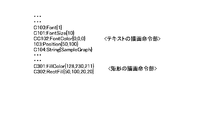
次に、第4の実施の形態の処理を詳細に説明する。まず、対象となる画像データが入力されるが、ここでは、ページ記述言語(以下PDL)で記述された入力画像データを前提として説明する。PDLとは、プリンタに対して描画を指示するためのプログラミング言語のことであり、文字や図形、その描画位置や色などを指定することができる。図16は、PDLによって記述された入力画像データの例を示す。 Next, the process of the fourth embodiment will be described in detail. First, target image data is input. Here, description will be made on the premise of input image data described in a page description language (hereinafter referred to as PDL). PDL is a programming language for instructing the printer to perform drawing, and can specify characters, figures, drawing positions, colors, and the like. FIG. 16 shows an example of input image data described by PDL.
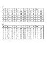
入力画像データが入力されると、色抽出部401は、入力画像データ中の文字や図形の色情報を抽出する。具体的には、図17における、FontColor、FillColorといった、文字色や領域の塗りつぶし色に関する記述を探索し、それに続く数値データ(RGB値)を抽出していく。その際、既に抽出された色と同一の色であった場合には、重複して抽出しない。図19(a)は抽出例である。No.は抽出された順番、RGBは、使用色のRGB値であり、その他は、色信号変換部403などにより用いられるため、この時点では全て0で初期化された状態である。このように抽出された使用色情報と入力画像データが面積評価部402へ送られる。また、色調整部406へは入力画像データのみが送られる。
When input image data is input, the
面積評価部402は、入力画像データと使用色情報を受け取ると、使用色の用いられている領域の面積の評価を行う。面積評価部402は、図19(a)に示すような使用色情報の1色目のRGB値を参照し、入力画像データ中の同じRGB値が設定されている部分を探す。そして、面積評価部402は、一致する色情報が見つかったら、その周辺でFontSizeやRectFillといった、文字サイズや塗りつぶし領域の大きさの情報を持った記述を探す。そして、面積評価部402は、FontSizeであればその2乗値を、図形であればその面積を、面積情報として設定する。図17の例であれば、C302:RectFillの後の4つの数値は、{x座標、y座標、幅、高さ}を示している。このため、面積評価部402は、幅×高さ、すなわち、20*20=400を面積情報とする。文字列であれば、面積評価部402は、C101で指定されたフォントサイズ10の2乗で100を面積情報とする。このように、面積評価部402は、使用色毎に、面積情報を算出していき、同一の色について、複数箇所に用いられている場合には、最小面積を面積評価値として採用する。すなわち、円グラフとその凡例などであれば、一般的には円弧・扇形の部分の面積ではなく、凡例の部分の面積を採用することになる。このように算出された面積情報(S)が付加された使用色情報(図19(b))が、色信号変換部403へと送られる。
Upon receiving the input image data and the use color information, the area evaluation unit 402 evaluates the area of the area where the use color is used. The area evaluation unit 402 refers to the RGB value of the first color of the used color information as shown in FIG. 19A and searches for a portion where the same RGB value is set in the input image data. When the matching color information is found, the area evaluation unit 402 searches for a description having information on the character size and the size of the filled area, such as FontSize and RectFill, in the vicinity thereof. Then, the area evaluation unit 402 sets the square value as the area information if it is FontSize and the area if it is a figure. In the example of FIG. 17, the four numerical values after C302: RectFill indicate {x coordinate, y coordinate, width, height}. For this reason, the area evaluation unit 402 sets width × height, that is, 20 * 20 = 400 as area information. If it is a character string, the area evaluation unit 402 sets 100 as the area information by the square of the
色信号変換部403は、面積評価部402から使用色情報を受け取ると、使用色毎に、RGB(ここでは、sRGB)値を中間色信号(ここでは、CIELAB)へと変換する。中間色信号への変換では、色信号変換部403は、まず、入力されたsRGB色信号をsRGBの仕様(IEC/4WD 61966−2−1:Colour Measurement and Management in Multimedia Systems and Equipment−Part 2−1: Default RGB Colour Space−sRGB)に基づき、XYZ三刺激値へと変換する(上述の(1)式〜(3)式)。さらに、色信号変換部403は、CIELAB表色系の定義に従い、L*a*b*値を算出する。色信号変換部403は、このように算出した中間色信号を付加した使用色情報(図20(a))を使用色分類部404と識別性評価部405へと送る。
When the color
使用色分類部404は、色信号変換部403から使用色情報を受け取ると、各使用色をb*成分の正負に応じて2つのグループに分け、その分類情報を識別性評価部405へと送る。図20(a)の例であれば、b*値がマイナスのNo.1,4,5(Gr=1)と、プラスのNo.2,3,6(Gr=2)の2つに分類される。識別性評価部405は、色信号変換部403から使用色情報を、使用色分類部404から使用色のグループ情報Grを受け取ると、分類されたグループ毎に、識別性の評価を行う。識別性評価部405は、分類後のグループ毎に、グループ内での全ての色の組合せに対して識別性を評価する。識別性評価部405は、あらかじめ主観評価実験などを行い、明度差やその他の色成分の差異と、識別しやすさを関連付ける評価式を構築しておき、それを用いて識別性を評価する。以下の(9)式に識別性評価式の一例を示す。
![]()
![]()
(9)式において、Sは評価対象領域の面積、ΔL*は、評価対象と比較対象の2色の明度差、Δb*は2色のb*成分差である。面積が小さいほど、評価値Distは小さくなる。また、ΔL*やΔb*についても同様である。 In equation (9), S is the area of the evaluation target region, ΔL * is the brightness difference between the two colors of the evaluation target and the comparison target, and Δb * is the b * component difference of the two colors. The smaller the area, the smaller the evaluation value Dist. The same applies to ΔL * and Δb *.
図20(b)において、例えば、No.1の識別性を評価する場合には、同じグループ内のNo.4及び5に対して識別性の評価を行う。 In FIG. 20B, for example, No. No. 1 in the same group is evaluated. 4 and 5 are evaluated for discrimination.
No.4に対して評価する場合、以下のようになる。
Dist.=100/225*(0.167*|47.09−41.96|+0.125*|−33.08+26.63|)=0.74
No. When evaluating 4, it becomes as follows.
Dist. = 100/225 * (0.167 * | 47.09-41.96 | + 0.125 * | -33.08 + 26.63 |) = 0.74
No.5に対しては、以下のようになる。
Dist.=100/225*(0.167*|47.09−58.67|+0.125*|−33.08+19.78|)=1.60
No. For 5, it is as follows.
Dist. = 100/225 * (0.167 * | 47.09-58.67 | + 0.125 * | -33.08 + 19.78 |) = 1.60
この場合、より識別性の低い方の0.74をNo.1の識別性評価値として採用する(図20(b))。 In this case, 0.74 having a lower discriminability is set to No. This is adopted as a discrimination evaluation value of 1 (FIG. 20B).
一方、No.2の識別性評価は、No.3とNo.6に対して、それぞれ評価値が5.81、6.88となり、5.81を評価値とする。このようにして算出した識別性評価値Distが使用色情報に付加され、色調整部406へと送られる。
On the other hand, no. The discriminability evaluation of No. 2 3 and no. With respect to 6, the evaluation values are 5.81 and 6.88, respectively, and 5.81 is the evaluation value. The discriminant evaluation value Dist calculated in this way is added to the used color information and sent to the
色調整部406は、識別性評価部405より使用色情報(図20(b))を受け取ると共に、色抽出部401から入力画像データを受け取る。色調整部406は、受け取った使用色情報において、識別性の評価値(Dist.)に所定値(例えば2.5)未満の値があった場合、その色を含むグループ内の色に対して識別性向上のための色調整を行う。以下、その色調整について説明する。
The
図20(b)において、まず、L*が中央となる色を決める。この例ではNo.1,4,5であるから、No.1の明度が3色の中央となる。そして、その色を固定し、その他の2色の明度を、評価値が所定値(例えば2.5)以上となるように調整する(図21(a))。(但し、中央の色の明度が40〜60の範囲から外れるように、偏りがある場合には、中央の明度が例えば50になるように、他の色も一律に同明度だけ調整し、その調整後の色に対し、以下の調整を行う)。この際、Δb*の値は、最初は固定し、明度のみを調整する。No.5の色については、明度を70.87とすると、評価値が2.5となり、No.1との識別性が所定値以上となる。一方、No.4については、明度を20.0としても識別性が2.37にしかならず、十分な識別性が確保できているとは言えない。なお、明度を20としたのは、カラープリンタ等の画像形成装置の色再現範囲を考慮したもので、ここでは、これ以上明度を下げると表現できなくなる明度の下限値として20としている。但し、画像形成方式などにより、色再現範囲は大きく異なるため、下限を20よりも大きく又は小さく設定しても良い。同様に、上限についても、ここでは80を想定して70.87を許容したが、画像形成方式によっては、70程度に上限を設定することもありうる。 In FIG. 20B, first, a color having L * as the center is determined. In this example, no. Nos. 1, 4 and 5 The brightness of 1 is the center of the three colors. Then, the color is fixed, and the brightness of the other two colors is adjusted so that the evaluation value becomes a predetermined value (for example, 2.5) or more (FIG. 21A). (However, if there is a deviation so that the lightness of the center color is out of the range of 40-60, other colors are also adjusted by the same lightness uniformly so that the lightness of the center is 50, for example. Make the following adjustments to the adjusted color): At this time, the value of Δb * is fixed at first and only the brightness is adjusted. No. For the color No. 5, if the brightness is 70.87, the evaluation value is 2.5. The discriminability from 1 is equal to or greater than a predetermined value. On the other hand, no. For 4, the discriminability is only 2.37 even if the brightness is 20.0, and it cannot be said that sufficient discriminability is secured. Note that the lightness is 20 in consideration of the color reproduction range of an image forming apparatus such as a color printer. Here, the lightness is set to 20 as the lower limit of lightness that cannot be expressed when the lightness is further lowered. However, since the color reproduction range varies greatly depending on the image forming method or the like, the lower limit may be set larger or smaller than 20. Similarly, for the upper limit, 70.87 is allowed assuming 80, but the upper limit may be set to about 70 depending on the image forming method.
ところで、No.4について、明度を下げてもNo.1との識別性が確保できないため、このような場合には、L*の次に、b*成分を調整する。No.1のb*成分との差分値を拡大するため、b*成分を23.9程度に調整すると、評価値がおよそ2.5となり、識別性が所定値以上となる(図21(a))。以上のように調整したL*a*b*値をS14の逆変換によりsRGB値に変換して生成した、色調整テーブルが図21(b)である。 By the way, no. For No. 4, even if the brightness was lowered, In such a case, the b * component is adjusted next to L * because the distinguishability from 1 cannot be ensured. No. If the b * component is adjusted to about 23.9 in order to expand the difference value with the b * component of 1, the evaluation value becomes approximately 2.5, and the discriminability becomes a predetermined value or more (FIG. 21A). . FIG. 21B shows a color adjustment table generated by converting the L * a * b * values adjusted as described above into sRGB values by the inverse transformation of S14.
色調整部406は、入力画像データ中のFontColorやFillColorの記述のRGB値とテーブルのRGB値が一致した場合に、調整後のR’G’B’値へと置換する。その一例が図18である。C102及びC301の文字色や塗りつぶし領域の色の情報のみが置き換わっている。
The
以上、識別性向上のための色調整について説明したが、対象とする色覚タイプはP/D型を前提としている。T型色覚者の識別性を向上させようとする場合には、識別性評価や色調整処理において、b*をa*に置き換えて実施すれば良い。すなわち、P/D型色覚者はL*方向及びb*方向の色成分の違いは一般色覚者と同等以上に識別できるが、a*方向の色成分の違いが分からないため、L*及びb*成分の差異を強調することで識別性を向上している。一方、T型色覚者においては、L*とa*は一般色覚者と同等以上だが、b*成分の違いが分かりにくいため、L*及びa*成分の差異を強調する必要がある。 Although the color adjustment for improving the discrimination has been described above, the target color vision type is premised on the P / D type. In order to improve the discrimination of a T-type color vision person, b * may be replaced with a * in the discrimination evaluation and color adjustment processing. That is, the difference between the color components in the L * direction and the b * direction can be discriminated to be equal to or greater than that of the general color sense person, but the difference in the color components in the a * direction is not known. * The distinctiveness is improved by emphasizing the differences in the components. On the other hand, in a T-type color vision person, L * and a * are equal to or greater than those of a general color vision person, but since the difference between b * components is difficult to understand, it is necessary to emphasize the difference between the L * and a * components.
以上説明した実施の形態では、入力画像データに使用されている色を、面積を考慮した識別性の評価に応じて色調整を行うことで、色弱者が小面積の凡例を含むグラフ画像などを閲覧する場合であっても、容易に色同士を識別することが可能な色調整を行うことが可能である。また、b*成分の正負などに応じてグループ分けし、グループ毎に色調整することで、比較的色混同の起きにくい色同士の識別性を考慮することなく、容易に色調整が可能である。 In the embodiment described above, the color used for the input image data is adjusted according to the evaluation of the distinctiveness in consideration of the area. Even in the case of browsing, it is possible to perform color adjustment that can easily identify colors. In addition, by performing grouping according to the positive / negative of the b * component and performing color adjustment for each group, it is possible to easily perform color adjustment without considering distinguishability between colors that are relatively unlikely to cause color confusion. .
本実施の形態によれば、入力画像データ中の塗りつぶし領域の面積に応じて識別性の評価及び色調整を行っているため、グラフの凡例や文字の色のような、色の違いが分かりにくいような色であっても、色弱者にとって識別性の良くなるような色調整を行うことが可能である。また、P/D型の色弱者が、一般色覚者と同等以上に識別しやすい輝度成分と所定の第2の色信号成分を調整しているので、P/D型色弱者であっても、識別性の良くなるような色調整を行うことが可能である。また、T型の色弱者が、一般色覚者と同等以上に識別し易い輝度成分と所定の第3の色信号成分を調整しているので、T型色弱者であっても、識別性の良くなるような色調整を行うことが可能である。さらに、面積が小さいほど、色調整量を大きくしているので、グラフの凡例や色文字といった、色を認識しづらい対象に対しても、色の識別性が良くなるような色調整を行うことが可能である。 According to the present embodiment, the distinctiveness evaluation and the color adjustment are performed according to the area of the filled area in the input image data, so that the color difference such as the legend of the graph and the color of the character is difficult to understand. Even with such a color, it is possible to perform color adjustment that makes the color weaker more identifiable. In addition, since the P / D type color weak person adjusts the luminance component and the predetermined second color signal component that are easily identified as equal to or higher than those of the general color vision person, It is possible to perform color adjustment that improves discrimination. In addition, since the T-type color weak person adjusts the luminance component and the predetermined third color signal component that are more easily identified as those of the general color vision person, the T-type color weak person has good discrimination. It is possible to perform such color adjustment. In addition, the smaller the area, the greater the amount of color adjustment, so color adjustment that improves color discrimination is possible even for objects that are difficult to recognize colors, such as graph legends and color characters. Is possible.
(第5の実施の形態)
第5の実施の形態は、入力画像データ中の使用色をb*成分の正負で2つのグループに分けた場合に、グループ間でb*成分の差異が所定値よりも小さい色があった場合に、あらかじめb*成分の差異を強調した上で、グループ毎に識別性の評価や色調整を行う。
(Fifth embodiment)
In the fifth embodiment, when the colors used in the input image data are divided into two groups according to the positive / negative of the b * component, there is a color in which the difference in the b * component is smaller than a predetermined value between the groups. In addition, after highlighting the difference of the b * component in advance, evaluation of discrimination and color adjustment are performed for each group.
図16は、第5の実施の形態に係る色調整装置としての画像処理装置500の構成例を示すブロック図である。第5の実施の形態では、第4の実施の形態の構成に、第2色調整部407を追加している。図15は、第4および第5の実施の形態の処理フローチャートである。第5の実施の形態では、ステップ16、17の処理を実行する。
FIG. 16 is a block diagram illustrating a configuration example of an
以下、第2色調整部407における処理について説明する。第2色調整部407は、色信号変換部403から使用色情報を受け取ると共に、使用色分類部404から使用色グループ情報を受け取ると、分類されたグループ間で、b*成分の最小となる2色を抽出する。すなわち、第2色調整部407は、b*成分がプラスのグループであればb*が最小の色を抽出し、b*成分がマイナスのグループであればb*成分が最大(絶対値が最小)の色を抽出する(図20(b)から、それぞれ、No.2とNo.5が該当することが分かる。)。そして、第2色調整部407は、それら2色のb*成分差(絶対値)を算出する。図20(b)の例では、第2色調整部407は、以下のようにb*成分差Δb*を算出する。
Δb*=22.66−(−19.78)=42.44
Hereinafter, processing in the second color adjustment unit 407 will be described. When the second color adjustment unit 407 receives the use color information from the color
Δb * = 22.66 − (− 19.78) = 42.44
この値が所定値(例えば45)未満であった場合、b*成分の差異(絶対値)を拡大する(ステップS16,17)。 If this value is less than a predetermined value (for example, 45), the difference (absolute value) of the b * component is enlarged (steps S16 and S17).
No.2の色については、
b*=b*+(45−42.44)/2=23.94
No.5の色については、
b*=b*−(45−42.44)/2=−21.06
となる。
No. For
b * = b * + (45−42.44) /2=23.94
No. For
b * = b * − (45−42.44) /2=−21.06
It becomes.
そして、第2色調整部407は、この処理により、それぞれのグループでb*の最小もしくは最大となる色に変化があった場合には、それら2色についても同様の処理を行い、グループ間で最も近い色同士のb*成分の差が45以上になるまで繰り返す。ここでは一例として閾値を45としているが、これに限定されるものではなく、使用色の面積が非常に大きい場合はこれよりももっと小さい値でも良いし、面積が非常に小さい場合には、さらに大きな値を用いる必要がある。以下、ステップS18以降、第4の実施の形態と同様の処理を行う。 Then, when there is a change in the minimum or maximum color of b * in each group as a result of this processing, the second color adjustment unit 407 performs the same processing for these two colors, and between the groups. Repeat until the b * component difference between the closest colors reaches 45 or more. Here, the threshold value is set to 45 as an example. However, the threshold value is not limited to this. If the area of the used color is very large, a smaller value may be used, and if the area is very small, It is necessary to use a large value. Thereafter, after step S18, the same processing as in the fourth embodiment is performed.
b*成分の正負により使用色を分類した場合、正負の色同士は、黄と青の全く別系統の色に見えるため、比較的混同しにくい。しかし、例えば、両方とも明度が低かった場合、両方とも暗い灰色に見えてしまい、混同してしまう可能性がある。 When the colors used are classified according to the positive / negative of the b * component, the positive and negative colors appear to be completely different colors of yellow and blue, and are relatively difficult to confuse. However, for example, if both are low in brightness, they both appear dark gray and may be confused.
以上説明した実施の形態では、使用色をb*成分の正負で2つに分類した後、それぞれのグループ間で最もb*成分差の小さい色同士に対して、その差異を所定値以上になるようにあらかじめ調整しているため、それぞれのグループ毎に色調整を行っても、全ての使用色の識別性を確保することができる。本実施の形態についても、T型色弱者の識別性を向上させる場合には、b*をa*に置き換えれば良いのは明らかである。 In the embodiment described above, after the use color is classified into two according to the positive / negative of the b * component, the difference between the groups having the smallest difference in the b * component is equal to or greater than a predetermined value. Therefore, even if color adjustment is performed for each group, it is possible to ensure the distinguishability of all used colors. Also in the present embodiment, it is obvious that b * may be replaced with a * in order to improve the discrimination of the T-type color weak.
本実施の形態によれば、入力画像データ中の使用色を分類し、分類したグループ間での最小のb*もしくはa*成分差が所定値以上になるようにしているので、グループ間で色みの近い色があった場合にも、識別性が良くなるような色調整を行うことが可能である。 According to the present embodiment, the colors used in the input image data are classified, and the minimum b * or a * component difference between the classified groups is equal to or greater than a predetermined value. Even when there is a close color, it is possible to perform color adjustment that improves discrimination.
図22は、上記各実施の形態をソフトウェアで実施する場合の画像処理装置のハードウェア構成例を示す図である。上記各実施の形態の画像処理装置に相当するコンピュータ600は、プログラム読取装置600a、全体を制御するCPU600b、CPU600bのワークエリア等として使用されるRAM600c、CPU600bの制御プログラム等が記憶されているROM600d、ハードディスク600e、NIC600f、マウス600g、キーボード600h、画像データの表示およびユーザーが画面に直接触れることで情報の入力が可能なディスプレイ601、カラープリンタ等の画像形成装置602とを備えている。本画像処理装置は、例えばワークステーションやパーソナル・コンピュータ等で実現することができる。
FIG. 22 is a diagram illustrating a hardware configuration example of the image processing apparatus when the above embodiments are implemented by software. A
このような構成の場合、図1および図10に示した各構成部(出力形態指定部1、色変換部2、画像形成制御部3、画像形成部6等)、および、図14、16に示した色抽出部401、面積評価部402、色信号変換部403、使用色分類部404、識別性評価部405、色調整部406、第2色調整部407の機能はCPU600bに実行させることができる。また、入力画像データは、DISK100eやRAM600c、ROM600dのいずれかに保持されたものを読み出したり、NIC600fから入力させることができる。なお、CPU600bで行われる画像処理機能は、例えばソフトウェアパッケージ、具体的には、CD−ROMや磁気ディスク等の情報記録媒体の形で提供することができる。このため、図22に示す例では、情報記録媒体がセットされると、これを駆動する図示しない媒体駆動装置が設けられている。
In the case of such a configuration, each component (output
以上により、本発明における色調整方法(画像処理方法)は、ディスプレイ等を備えた汎用の計算機システムにCD−ROM等の情報記録媒体に記録されたプログラムを読み込ませて、この汎用計算機システムの中央演算装置に色調整処理(画像処理)を実行させる装置構成においても実施することが可能である。この場合、本発明の色調整処理(画像処理)を実行するためのプログラム、すなわちハードウェアシステムで用いられるプログラムは、記録媒体に記録された状態で提供される。プログラムなどが記録される情報記録媒体としては、CD−ROMといったものに限定されるものではなく、例えばROM、RAM、フラッシュメモリ、光磁気ディスクといったものが用いられても良い。記録媒体に記録されたプログラムは、ハードウェアシステムに組み込まれている記憶装置、例えばハードディスク600eにインストールされることにより、このプログラムを実行して、画像処理機能を実現することができる。また、上記実施の形態の機能等を実現するためのプログラムは、ネットワークを介した通信によってサーバから提供されるものでも良い。
As described above, the color adjustment method (image processing method) according to the present invention causes a general-purpose computer system equipped with a display or the like to read a program recorded on an information recording medium such as a CD-ROM, and the center of the general-purpose computer system. The present invention can also be implemented in an apparatus configuration that causes a computing device to perform color adjustment processing (image processing). In this case, a program for executing the color adjustment processing (image processing) of the present invention, that is, a program used in the hardware system is provided in a state recorded in a recording medium. The information recording medium on which the program or the like is recorded is not limited to a CD-ROM, and for example, a ROM, RAM, flash memory, magneto-optical disk, or the like may be used. The program recorded on the recording medium is installed in a storage device incorporated in the hardware system, for example, the
1 出力形態指定部
2、202、302 色変換部
3 画像形成制御部
4 色信号置換部
5 色逆変換部
6 画像形成部
21、321 第1色信号変換部
22、322 第2色信号変換部
23、323 第3色信号変換部
24、324 第4色信号変換部
25 合成部
41 色差評価部
42 色置換部
100、300、400、500 画像処理装置
401 色抽出部
402 面積評価部
403 色信号変換部
404 使用色分類部
405 識別性評価部
406 (第1)色調整部
407 第2色調整部
DESCRIPTION OF
Claims (15)
前記使用色で塗りつぶされた領域の面積を算出する面積評価部と、
前記面積に基づいて、領域の識別性を評価する識別性評価値を算出する識別性評価部と、
前記識別性評価値が所定値より小さい場合に、前記入力画像データの対応する領域の識別性を向上させる色調整を行う色調整部と、
色調整後の前記入力画像データを画像形成に用いる画像形成用データに変換する色変換部と、
前記画像形成用データによる画像形成を制御する制御部と、を備え、
前記色変換部は、前記入力画像データの色空間に含まれる色のうち、色弱者が相互に判別することが困難な色として予め定められた複数の色それぞれを、前記画像形成用データの色空間の同一色に変換すること、
を特徴とする画像処理装置。 A color extraction unit for extracting a used color used for filling from input image data;
An area evaluation unit for calculating the area of the region filled with the use color;
Based on the area, a distinguishability evaluation unit that calculates a distinguishability evaluation value for evaluating the distinguishability of the region;
A color adjustment unit that performs color adjustment to improve the identification of a corresponding region of the input image data when the identification evaluation value is smaller than a predetermined value;
A color conversion unit that converts the input image data after color adjustment into data for image formation used for image formation;
A control unit for controlling image formation by the image forming data,
The color conversion unit converts each of a plurality of colors that are determined in advance as colors that are difficult for color-weak persons to distinguish from each other in the color space of the input image data. Converting to the same color in space,
An image processing apparatus.
を特徴とする請求項1に記載の画像処理装置。 The image processing apparatus according to claim 1.
を特徴とする請求項1に記載の画像処理装置。 The image processing apparatus according to claim 1.
を特徴とする請求項3に記載の画像処理装置。 The image processing apparatus according to claim 3.
を特徴とする請求項3に記載の画像処理装置。 The image processing apparatus according to claim 3.
前記色変換部は、前記変換テーブルを用いて前記入力画像データを前記画像形成用データに変換すること、
を特徴とする請求項1に記載の画像処理装置。 A table associating the color of the color space of the input image data with the color of the color space of the image forming data, and a plurality of predetermined colors that are difficult for color-weak persons to distinguish from each other A storage unit that stores a conversion table in which a predetermined specific color is associated with the color;
The color conversion unit converts the input image data into the image forming data using the conversion table;
The image processing apparatus according to claim 1.
前記制御部は、複数の色覚特性それぞれに対して変換された複数の前記画像形成用データによる画像形成を制御すること、
を特徴とする請求項1に記載の画像処理装置。 The color conversion unit determines, for each of the plurality of color vision characteristics, a plurality of colors that are determined in advance as colors that are difficult for color-blind persons of the color vision characteristics to distinguish each other. Convert to the same color,
The control unit controls image formation by the plurality of image forming data converted for each of a plurality of color vision characteristics;
The image processing apparatus according to claim 1.
前記制御部は、前記合成画像データの出力を制御すること、
を特徴とする請求項7に記載の画像処理装置。 The color conversion unit further generates combined image data obtained by converting pixels converted to the same color with at least one of the plurality of image forming data for each of a plurality of color vision characteristics into a predetermined color,
The control unit controls the output of the composite image data;
The image processing apparatus according to claim 7 .
前記色変換部は、前記変換テーブルを用いて前記入力画像データを前記画像形成用データに変換し、さらに、予め定められた評価式により、前記画像形成用データの相互に隣接する画素間の色の色差を算出し、算出した色差が予め定められた閾値より小さい場合に、色差が前記閾値より小さい複数の画素それぞれを予め定められた色に変換すること、
を特徴とする請求項1に記載の画像処理装置。 A storage unit that stores a conversion table that associates the color of the color space of the input image data with the color of the color space of the image forming data;
The color conversion unit converts the input image data into the image forming data using the conversion table, and further, a color between adjacent pixels of the image forming data according to a predetermined evaluation formula. When the calculated color difference is smaller than a predetermined threshold, and each of a plurality of pixels having a color difference smaller than the threshold is converted into a predetermined color.
The image processing apparatus according to claim 1.
を特徴とする請求項1に記載の画像処理装置。 The color conversion unit converts each of a plurality of colors that are determined in advance as colors that are difficult for color-weak persons to distinguish from each other in the color space of the input image data. Converting to one of the corresponding colors in space,
The image processing apparatus according to claim 1.
を特徴とする請求項1に記載の画像処理装置。 The color conversion unit converts each of a plurality of colors that are determined in advance as colors that are difficult for color-weak persons to distinguish from each other in the color space of the input image data. Converting it to black in space,
The image processing apparatus according to claim 1.
を特徴とする請求項1に記載の画像処理装置。 Among the colors included in the color space of the input image data, a plurality of colors that are determined in advance as colors that are difficult for the color weak to distinguish from each other are converted to the same color in the color space of the image forming data. Further comprising a notification unit for notifying the effect,
The image processing apparatus according to claim 1.
前記使用色で塗りつぶされた領域の面積を算出する面積評価ステップと、
前記面積に基づいて、領域の識別性を評価する識別性評価値を算出する識別性評価ステップと、
前記識別性評価値が所定値より小さい場合に、前記入力画像データの対応する領域の識別性を向上させる色調整を行う色調整ステップと、
色調整後の前記入力画像データを画像形成に用いる画像形成用データに変換する色変換ステップと、
前記画像形成用データによる画像形成を制御する制御ステップと、を含み、
前記色変換ステップは、前記入力画像データの色空間に含まれる色のうち、色弱者が相互に判別することが困難な色として予め定められた複数の色それぞれを、前記画像形成用データの色空間の同一色に変換すること、
を特徴とする画像処理方法。 A color extraction step for extracting the used color used for filling from the input image data;
An area evaluation step for calculating an area of the region filled with the use color;
A discriminability evaluation step for calculating a discriminability evaluation value for evaluating the discriminability of the region based on the area;
A color adjustment step for performing color adjustment to improve the discrimination of the corresponding region of the input image data when the discrimination evaluation value is smaller than a predetermined value;
A color conversion step of converting the input image data after color adjustment into image formation data used for image formation;
Controlling the image formation by the image forming data,
In the color conversion step, among the colors included in the color space of the input image data, each of a plurality of colors that are determined in advance as colors that are difficult for the color weak to distinguish each other is used as the color of the image forming data. Converting to the same color in space,
An image processing method characterized by the above.
Priority Applications (2)
| Application Number | Priority Date | Filing Date | Title |
|---|---|---|---|
| JP2010109636A JP5589544B2 (en) | 2009-06-17 | 2010-05-11 | Image processing apparatus, image processing method, program, and recording medium |
| US12/801,506 US8514239B2 (en) | 2009-06-17 | 2010-06-11 | Image processing apparatus, image processing method, and computer program product |
Applications Claiming Priority (3)
| Application Number | Priority Date | Filing Date | Title |
|---|---|---|---|
| JP2009143814 | 2009-06-17 | ||
| JP2009143814 | 2009-06-17 | ||
| JP2010109636A JP5589544B2 (en) | 2009-06-17 | 2010-05-11 | Image processing apparatus, image processing method, program, and recording medium |
Publications (2)
| Publication Number | Publication Date |
|---|---|
| JP2011024191A JP2011024191A (en) | 2011-02-03 |
| JP5589544B2 true JP5589544B2 (en) | 2014-09-17 |
Family
ID=43353925
Family Applications (1)
| Application Number | Title | Priority Date | Filing Date |
|---|---|---|---|
| JP2010109636A Active JP5589544B2 (en) | 2009-06-17 | 2010-05-11 | Image processing apparatus, image processing method, program, and recording medium |
Country Status (2)
| Country | Link |
|---|---|
| US (1) | US8514239B2 (en) |
| JP (1) | JP5589544B2 (en) |
Cited By (1)
| Publication number | Priority date | Publication date | Assignee | Title |
|---|---|---|---|---|
| US9984609B2 (en) | 2015-01-26 | 2018-05-29 | Samsung Display Co., Ltd. | Display device |
Families Citing this family (8)
| Publication number | Priority date | Publication date | Assignee | Title |
|---|---|---|---|---|
| US8526724B2 (en) * | 2010-11-17 | 2013-09-03 | Microsoft Corporation | In-image accessibility indication |
| JP5562812B2 (en) * | 2010-11-22 | 2014-07-30 | 株式会社東芝 | Transmission / reception switching circuit, radio apparatus, and transmission / reception switching method |
| JP6102215B2 (en) * | 2011-12-21 | 2017-03-29 | 株式会社リコー | Image processing apparatus, image processing method, and program |
| US8792138B2 (en) * | 2012-02-08 | 2014-07-29 | Lexmark International, Inc. | System and methods for automatic color deficient vision correction of an image |
| US9142186B2 (en) | 2012-06-20 | 2015-09-22 | International Business Machines Corporation | Assistance for color recognition |
| CN104349013B (en) * | 2013-08-09 | 2018-09-28 | 富士施乐株式会社 | Image forming apparatus, image formation system and image forming method |
| EP3794580A4 (en) * | 2018-05-18 | 2022-03-16 | Faurecia Irystec Inc. | System and method for color mapping for improved viewing by a color vision deficient observer |
| WO2020202746A1 (en) * | 2019-03-29 | 2020-10-08 | ソニー株式会社 | Information processing device, information processing method, and computer program |
Family Cites Families (12)
| Publication number | Priority date | Publication date | Assignee | Title |
|---|---|---|---|---|
| JPH0682385B2 (en) * | 1987-05-15 | 1994-10-19 | 日本放送協会 | Color vision converter |
| JPH0816129A (en) * | 1994-04-27 | 1996-01-19 | Canon Inc | Picture processing device |
| JP4155051B2 (en) | 2003-02-14 | 2008-09-24 | 富士ゼロックス株式会社 | Document processing device |
| EP1453006A1 (en) * | 2003-02-28 | 2004-09-01 | Océ-Technologies B.V. | Converted digital colour image with improved colour distinction for colour-blinds |
| JP3867988B2 (en) | 2004-11-26 | 2007-01-17 | 株式会社両備システムソリューションズ | Pixel processing device |
| JP2006246072A (en) | 2005-03-03 | 2006-09-14 | Ricoh Co Ltd | Image forming device, image forming method, image forming program, and computer readable recording medium |
| JP2006350066A (en) | 2005-06-17 | 2006-12-28 | Toyo Ink Mfg Co Ltd | Color sample selection device |
| JP4948912B2 (en) | 2006-06-15 | 2012-06-06 | パイオニア株式会社 | Display system |
| JP2008185688A (en) * | 2007-01-29 | 2008-08-14 | Sanyo Electric Co Ltd | Color display device |
| JP2008275776A (en) * | 2007-04-26 | 2008-11-13 | Sanyo Electric Co Ltd | Color display device |
| JP2008281819A (en) * | 2007-05-11 | 2008-11-20 | Sanyo Electric Co Ltd | Color display device |
| JP2009124221A (en) * | 2007-11-12 | 2009-06-04 | Fuji Xerox Co Ltd | Image processing apparatus, and image processing program |
-
2010
- 2010-05-11 JP JP2010109636A patent/JP5589544B2/en active Active
- 2010-06-11 US US12/801,506 patent/US8514239B2/en active Active
Cited By (1)
| Publication number | Priority date | Publication date | Assignee | Title |
|---|---|---|---|---|
| US9984609B2 (en) | 2015-01-26 | 2018-05-29 | Samsung Display Co., Ltd. | Display device |
Also Published As
| Publication number | Publication date |
|---|---|
| US8514239B2 (en) | 2013-08-20 |
| US20100321400A1 (en) | 2010-12-23 |
| JP2011024191A (en) | 2011-02-03 |
Similar Documents
| Publication | Publication Date | Title |
|---|---|---|
| JP5589544B2 (en) | Image processing apparatus, image processing method, program, and recording medium | |
| US7394468B2 (en) | Converted digital colour image with improved colour distinction for colour-blinds | |
| JP5437150B2 (en) | Method and system for highlighting topic elements in a chart having multiple contrast elements of multiple colors | |
| JP5685895B2 (en) | Image processing apparatus, image processing method, and program | |
| US8982411B2 (en) | Image processing apparatus and method | |
| US8390905B2 (en) | Image processing device extracting desired region to be used as model for image correction | |
| US7616216B2 (en) | Digital content creation system, program product, and storage medium | |
| JP2014165656A (en) | Color profile generation device, image processing apparatus, image processing system, color profile generation method and program | |
| EP1924076A2 (en) | Image Forming Apparatus and Image Forming Method Capable of Revising Gray Image | |
| JP2009071541A (en) | Image processor, image processing method, program, and recording medium | |
| US9986133B2 (en) | Method and system for color gamut expansion in print | |
| JP2011166558A (en) | Image processing apparatus, image printing system, image processing method and program | |
| JP5279085B2 (en) | Color arrangement conversion apparatus and program | |
| US8311323B2 (en) | Image processor for converting image by using image retrieved based on keyword | |
| US8094343B2 (en) | Image processor | |
| JP2008235965A (en) | Image processor, image processing method, program and recording medium | |
| JP2009060388A (en) | Image processor and image processing program | |
| JP2012244355A (en) | Image processing apparatus, program, and image formation apparatus | |
| JP6470379B1 (en) | Computer program, color chart, color code diagram ,. | |
| CN101848314B (en) | Image-processing device, image-forming device, image-processing method | |
| JP2021158588A (en) | Image processing device, image processing system, and program | |
| JP4974303B2 (en) | Color conversion information generation apparatus, color conversion information generation method and program | |
| JP2009218928A (en) | Image processing apparatus, image processing method, image processing program and image processing storage medium | |
| EP1453008A1 (en) | Cocverted digital colour image with improved colour distinction for colour-blinds | |
| JP2012245707A (en) | Apparatus, method, and program for image processing |
Legal Events
| Date | Code | Title | Description |
|---|---|---|---|
| A621 | Written request for application examination |
Free format text: JAPANESE INTERMEDIATE CODE: A621 Effective date: 20130218 |
|
| A977 | Report on retrieval |
Free format text: JAPANESE INTERMEDIATE CODE: A971007 Effective date: 20140121 |
|
| A131 | Notification of reasons for refusal |
Free format text: JAPANESE INTERMEDIATE CODE: A131 Effective date: 20140128 |
|
| A521 | Written amendment |
Free format text: JAPANESE INTERMEDIATE CODE: A523 Effective date: 20140324 |
|
| TRDD | Decision of grant or rejection written | ||
| A01 | Written decision to grant a patent or to grant a registration (utility model) |
Free format text: JAPANESE INTERMEDIATE CODE: A01 Effective date: 20140701 |
|
| A61 | First payment of annual fees (during grant procedure) |
Free format text: JAPANESE INTERMEDIATE CODE: A61 Effective date: 20140714 |
|
| R151 | Written notification of patent or utility model registration |
Ref document number: 5589544 Country of ref document: JP Free format text: JAPANESE INTERMEDIATE CODE: R151 |