JP5588940B2 - Photographic lens unit and operation control method thereof - Google Patents
Photographic lens unit and operation control method thereof Download PDFInfo
- Publication number
- JP5588940B2 JP5588940B2 JP2011164946A JP2011164946A JP5588940B2 JP 5588940 B2 JP5588940 B2 JP 5588940B2 JP 2011164946 A JP2011164946 A JP 2011164946A JP 2011164946 A JP2011164946 A JP 2011164946A JP 5588940 B2 JP5588940 B2 JP 5588940B2
- Authority
- JP
- Japan
- Prior art keywords
- control
- cpu board
- communication
- cpu
- data
- Prior art date
- Legal status (The legal status is an assumption and is not a legal conclusion. Google has not performed a legal analysis and makes no representation as to the accuracy of the status listed.)
- Active
Links
- 238000000034 method Methods 0.000 title description 16
- 238000004891 communication Methods 0.000 claims description 143
- 238000006243 chemical reaction Methods 0.000 claims description 25
- 238000003384 imaging method Methods 0.000 claims description 25
- 239000000758 substrate Substances 0.000 description 14
- 238000012545 processing Methods 0.000 description 10
- 239000004606 Fillers/Extenders Substances 0.000 description 7
- 230000005540 biological transmission Effects 0.000 description 6
- 230000006641 stabilisation Effects 0.000 description 6
- 238000011105 stabilization Methods 0.000 description 6
- 238000010586 diagram Methods 0.000 description 3
- 238000012937 correction Methods 0.000 description 2
- 230000006870 function Effects 0.000 description 2
- 238000012790 confirmation Methods 0.000 description 1
- 125000004122 cyclic group Chemical group 0.000 description 1
- 238000001514 detection method Methods 0.000 description 1
- 238000005516 engineering process Methods 0.000 description 1
- 238000011156 evaluation Methods 0.000 description 1
- 230000003287 optical effect Effects 0.000 description 1
- 230000004044 response Effects 0.000 description 1
- 238000012546 transfer Methods 0.000 description 1
Images


Landscapes
- Lens Barrels (AREA)
- Structure And Mechanism Of Cameras (AREA)
- Studio Devices (AREA)
Description
この発明は,撮影レンズ・ユニットおよびその動作制御方法に関する。 The present invention relates to a photographing lens unit and an operation control method thereof.
カメラ用交換レンズには,複数のマイクロコンピュータを備えているものがある(特許文献1)。複数のマイクロコンピュータのうちカメラとのデータのやり取りを行うマイクロコンピュータが選ばれる。また,カメラ本体とレンズ本体との電気的な通信を行うものもある(特許文献2)。さらに,カメラ本体と交換レンズ間に中間アクセサリが装着された場合に誤った補正が行われることを防止するものもある(特許文献3)。さらに,テレビレンズ装置の電力不足によるノイズの混入を防止するものもある(特許文献4)。 Some interchangeable lenses for cameras include a plurality of microcomputers (Patent Document 1). Among the plurality of microcomputers, a microcomputer that exchanges data with the camera is selected. In addition, there is one that performs electrical communication between the camera body and the lens body (Patent Document 2). Further, there is a technique that prevents erroneous correction when an intermediate accessory is mounted between the camera body and the interchangeable lens (Patent Document 3). Further, there is a TV lens device that prevents noise from being mixed due to power shortage (Patent Document 4).
図8は,従来の撮影レンズ・ユニットの電気的構成を示している。 FIG. 8 shows the electrical configuration of a conventional photographic lens unit.
従来の撮影レンズ・ユニットには,メイン基板120にメインCPU121が実装されている。撮影レンズ・ユニットに装着されるカメラ本体122およびCG(コンピュータ・グラフィック)などを行うためのバーチャル・システム123とメインCPU121とはRS232Cケーブルによってそれぞれ接続されている。また,外部装置からのズーム要求信号およびフォーカス要求信号はRS485ケーブルまたはアナログ信号ケーブルによってメインCPU121に与えられる。撮影レンズ・ユニットには,スイッチ134,135,表示装置136,137なども設けられており,これらのスイッチ134,135,表示装置136,137はアナログ信号ケーブルによってメインCPU121と接続されている。
In a conventional photographic lens unit, a
さらに,RS485ケーブルまたはアナログ信号ケーブルによってズーム・モータ125を制御するズーム・サーボ・モジュール基板124およびフォーカス・モータ128を制御するフォーカス・サーボ・モジュール基板127がメインCPU121と接続されている。さらに,ズーム・レンズの位置を検出するセンサ126,フォーカス・レンズの位置を検出するセンサ129,アイリス・モータ129,アイリスの絞り値を検出するセンサ131もアナログ信号ケーブルによってメインCPU121と接続されている。さらに,防振レンズを制御する防振ユニット基板132および合焦位置を算出するPFユニット基板133はRS232CケーブルによってメインCPU121と接続されている。
Further, a zoom
従来の撮影レンズ・ユニットでは,撮影レンズ・ユニットが制御する対象からの信号がすべてメインCPU121に入力している。メインCPU121が撮影レンズ・ユニットのすべての制御を統括するので,管理が難しいし,機能,性能を拡張すると処理時間が不足する可能性がある。また,メインCPU121に接続されるラインの数が多く,複雑とならざるを得ないし,機能拡張には高密度のメイン基板の変更が必要となってしまう。
In the conventional photographing lens unit, all signals from the object controlled by the photographing lens unit are input to the
メインCPU121に接続されるラインの数を少なくするために独立した複数の制御基板をネットワーク・ラインで通信可能に接続することが考えられる。ところが,複数の制御基板をネットワーク・ラインで通信可能に接続した場合においても,撮影レンズ・ユニットのすべての制御を統括するメインCPU基板が設けられると,複数の制御基板をネットワーク・ラインで通信可能に接続したメリットが半減してしまう。
In order to reduce the number of lines connected to the
この発明は,複数の制御基板をネットワーク・ラインで通信可能に接続した場合に,メインCPU基板が存在しなくともカメラ本体と通信できるようにすることを目的とする。 An object of the present invention is to enable communication with a camera body without a main CPU board when a plurality of control boards are communicably connected via a network line.
この発明による撮影レンズ・ユニットは,それぞれが独立している複数の制御基板のそれぞれに撮像装置による撮像を制御する制御回路が実装されており,かつ少なくとも2つ以上の制御基板の構造が同じであり,制御基板同士がネットワーク・ラインにより接続されている複数の制御基板,および上記複数の制御基板に含まれており,撮像装置と接続されるカメラ通信制御基板であって,撮像装置との通信に用いられる外部通信プロトコルと,ネットワーク・ラインを利用した撮影レンズ・ユニット内の制御基板との通信に用いられる内部通信プロトコルと,の間のプロトコル変換を行うカメラ通信制御基板を備えていることを特徴とする。 In the photographing lens unit according to the present invention, a control circuit for controlling imaging by the imaging device is mounted on each of a plurality of independent control boards, and the structure of at least two or more control boards is the same. A plurality of control boards that are connected to each other by a network line, and a camera communication control board that is included in the plurality of control boards and is connected to the imaging device, the communication with the imaging device A camera communication control board that converts the protocol between the external communication protocol used in the camera and the internal communication protocol used for communication with the control board in the taking lens unit using the network line Features.
この発明は,上記撮影レンズ・ユニットに適した動作制御方法も提供している。すなわち,この方法は,それぞれが独立している複数の制御基板のそれぞれに撮像装置による撮像を制御する制御回路が実装されており,かつ少なくとも2つ以上の制御基板の構造が同じであり,制御基板同士がネットワーク・ラインにより接続されている複数の制御基板を設け,上記複数の制御基板に含まれており,撮像装置と接続されるカメラ通信制御基板が,撮像装置との通信に用いられる外部通信プロトコルと,ネットワーク・ラインを利用した撮影レンズ・ユニット内の制御基板との通信に用いられる内部通信プロトコルと,の間のプロトコル変換を行うものである。 The present invention also provides an operation control method suitable for the photographic lens unit. That is, in this method, a control circuit for controlling imaging by an imaging device is mounted on each of a plurality of independent control boards, and the structure of at least two or more control boards is the same. A plurality of control boards connected to each other by a network line are provided, and the camera communication control board, which is included in the plurality of control boards and connected to the imaging device, is used for communication with the imaging device. It converts the protocol between the communication protocol and the internal communication protocol used for communication with the control board in the photographing lens unit using the network line.
この発明によると,それぞれが独立している複数の制御基板のそれぞれに撮像装置による撮像を制御する制御回路が実装されており,かつ少なくとも2つ以上の制御基板の構造が同じであり,制御基板同士がネットワーク・ラインにより接続されている複数の制御基板が設けられている。これらの複数の制御基板には,撮像装置と接続され,かつ撮像装置との通信に用いられる外部通信プロトコルと,ネットワーク・ラインを利用した撮影レンズ・ユニット内の制御基板との通信に用いられる内部通信プロトコルと,の間のプロトコル変換を行うカメラ通信制御基板が含まれている。カメラ通信制御基板により,撮像装置との通信に用いられる外部通信プロトコルと,ネットワーク・ラインを利用した撮影レンズ・ユニット内の制御基板との通信に用いられる内部通信プロトコルと,の間のプロトコル変換が行われるので,制御基板同士をネットワーク・ラインにより接続して通信させる場合において,外部通信プロトコルと内部通信プロトコルとのプロトコルが異なる場合であっても,撮影レンズ・ユニットとカメラ本体とを通信させることができる。カメラ本体から送信されたデータを撮影レンズ・ユニット内の各制御基板にネットワーク・ラインを介して送信できるようになる。 According to the present invention, the control circuit for controlling the imaging by the imaging device is mounted on each of the plurality of independent control boards, and the structure of at least two or more control boards is the same. A plurality of control boards connected to each other by a network line are provided. The plurality of control boards are connected to the image pickup apparatus and used for communication with the image pickup apparatus and the internal communication board used for communication with the control board in the photographing lens unit using the network line. A camera communication control board that performs protocol conversion between the communication protocol and the communication protocol is included. The camera communication control board enables protocol conversion between the external communication protocol used for communication with the imaging device and the internal communication protocol used for communication with the control board in the taking lens unit using the network line. Therefore, when the control boards are connected via a network line for communication, the photographic lens unit and the camera body can communicate with each other even if the external communication protocol and the internal communication protocol are different. Can do. Data transmitted from the camera body can be transmitted to each control board in the photographing lens unit via a network line.
上記カメラ通信制御基板は,たとえば,撮像装置から外部通信プロトコルによって送信された制御信号を,内部通信プロトコルに変換し,内部通信プロトコルに変換された制御信号を上記複数の制御基板のうち,一または複数の制御基板に送信するものである。 The camera communication control board converts, for example, a control signal transmitted from the imaging device using an external communication protocol into an internal communication protocol, and converts the control signal converted into the internal communication protocol into one or more of the plurality of control boards. The data is transmitted to a plurality of control boards.
上記カメラ通信制御基板は,上記複数の制御基板のそれぞれが制御する制御対象の状況を表わす状況データを周期的に検出し,検出された制御対象の状況を表わす状況データを記憶するメモリを備え,撮像装置から送信された制御信号に応じて,上記メモリに記憶されている状況データを外部通信プロトコルによって撮像装置に送信するものでもよい。 The camera communication control board includes a memory for periodically detecting situation data representing a situation of a controlled object controlled by each of the plurality of control boards, and storing situation data representing the detected situation of the controlled object, The status data stored in the memory may be transmitted to the imaging device by an external communication protocol in accordance with a control signal transmitted from the imaging device.
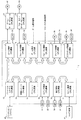
図1は,撮影レンズ・ユニット1の電気的構成を示すブロック図である。
FIG. 1 is a block diagram showing an electrical configuration of the taking
撮影レンズ・ユニット1には,それぞれが独立している(別々の基板)多数のCPU基板11−22(相互に着脱自在である)が含まれている。これらのCPU基板11−22のそれぞれにはCPUが実装されている。従来の撮影レンズ・ユニット1では,一つのCPUによって多数の処理が制御されているために,多数の処理を並行して行うことができないが,この実施例では,基板のそれぞれにCPUが実装されているので,それぞれの基板に実装されているCPUを同時に駆動することにより多数の処理を同時に行うことができる。
The taking
バーチャル・システムCPU基板12と防振ユニットCPU基板13とズーム制御CPU基板17,防振ユニットCPU基板13とPFユニットCPU基板14,PFユニットCPU基板14とスイッチCPU基板15,表示制御CPU基板16とカメラ通信CPU基板11は,それぞれネットワーク・ラインにより着脱自在に接続(バス接続)されている。
Virtual
また,ズーム制御CPU基板17とフォーカス制御CPU基板18,フォーカス制御CPU基板18とズーム要求CPU基板19,ズーム要求CPU基板19とフォーカス要求CPU基板20,フォーカス要求CPU基板20とアイリス制御CPU基板21,アイリス制御CPU基板21とエクステンダ制御CPU基板22もそれぞれネットワーク・ラインにより着脱自在に接続されている。
Further, the zoom
撮影レンズ・ユニット1に含まれるCPU基板11−22同士は,詳しくは後述するようにCAN(Controller Area Network)通信が利用される。
As described in detail later, CAN (Controller Area Network) communication is used between the CPU boards 11-22 included in the photographing
カメラ通信CPU基板11にはカメラ本体41がRS232Cケーブルによって接続されている。カメラ通信CPU基板11には,カメラ本体41から,画像データ,コマンド等がRS232Cケーブルを介して入力する。カメラ本体41とカメラ通信CPU基板11とはRS232Cケーブルで接続され,RS232Cにもとづくデータ通信が行われるのに対し,カメラ通信CPU基板11と撮影レンズ・ユニット1内のCPU基板12−22との通信はCAN通信である。このために,カメラ本体41からカメラ通信CPU基板11に入力するコマンド等はカメラ通信CPU基板11においてRS232Cにもとづくプロトコル(外部通信プロトコル)からCAN通信にもとづくプロトコル(内部通信プロトコル)に変換される。また,カメラ通信CPU基板11からカメラ本体41にデータ通信が行われる場合には,カメラ通信CPU基板11においてCAN通信にもとづくプロトコルからRS232Cにもとづくプロトコルに変換される。
A
CG(コンピュータ・グラフィック)処理を行うバーチャル・システム42などからの各種信号は,RS232Cケーブルなどによりバーチャル・システムCPU基板12に入力する。
Various signals from the virtual system 42 that performs CG (computer graphic) processing are input to the virtual
防振ユニットCPU基板13は,振れ方向に応じて振れ補正する防振レンズ(図示略)をシフトするものである。
The anti-vibration
PFユニットCPU基板21は,カメラ本体41に設けられている撮像用CCDの光学的距離から少し短い第1のAF用CCDと少し長い第2のAF用CCDと(いずれも図示略)から得られるAF評価値とフォーカス・レンズの位置との関係を表わす二つのグラフを生成し,その交点である合焦位置を算出するものである。
The PF
スイッチ制御CPU基板15は,各種スイッチ31,32からの信号にもとづいてスイッチ制御を行うものである。表示制御CPU基板16は,表示装置(インジケータ)33,34の表示を制御するものである。
The switch
ズーム制御CPU基板17には,ズーム・サーボ・モジュールCPU基板61および位置センサ51が接続されている。ズーム制御CPU基板17とズーム・サーボ・モジュールCPU基板61とはRS485ケーブルによって接続されている。ズーム制御CPU基板17と位置センサ51とはアナログ・ラインによって接続されている。もっとも,ズーム制御CPU基板17とズーム・サーボ・モジュールCPU基板61ともアナログ・ラインによって接続してもよい。ズーム・サーボ・モジュールCPU基板61には,ズーム・レンズ(図示略)を駆動するズーム・モータ22が接続されている。
The zoom
ズーム制御CPU基板17により,ズーム・サーボ・モジュールCPU基板61が制御される。ズーム・サーボ・モジュールCPU基板61によってズーム・モータ62が駆動され,ズーム・レンズが制御される。ズーム・レンズの位置は,位置センサ51によって検出される。
The zoom
フォーカス制御CPU基板18には,フォーカス・サーボ・モジュールCPU基板63および位置センサ52が接続されている。フォーカス制御CPU基板18とフォーカス・サーボ・モジュールCPU基板63とはRS485ケーブルによって接続されている。フォーカス制御CPU基板18と位置センサ52とはアナログ・ラインによって接続されている。もっとも,フォーカス制御CPU基板18とフォーカス・サーボ・モジュールCPU基板63ともアナログ・ラインによって接続してもよい。フォーカス・サーボ・モジュールCPU基板63には,フォーカス・レンズ(図示略)を駆動するフォーカス・モータ64が接続されている。
A focus servo
フォーカス制御CPU基板18により,フォーカス・サーボ・モジュールCPU基板63が制御される。フォーカス・サーボ・モジュールCPU基板63によってフォーカス・モータ64が駆動され,フォーカス・レンズが制御される。フォーカス・レンズの位置は,位置センサ52によって検出される。
The focus
撮影レンズ・ユニット1に与えられるズーム要求信号およびフォーカス要求信号は,ズーム要求CPU基板19およびフォーカス要求CPU基板20にそれぞれ与えられる。
The zoom request signal and the focus request signal given to the photographing
ズーム要求CPU基板19は,RS485ケーブル(またはアナログ・ライン)から与えられるズーム要求信号を受信して他の基板に送信するものである。フォーカス要求CPU基板20は,RS485ケーブル(またはアナログ・ライン)から与えられるフォーカス要求信号を受信して他の基板に送信するものである。
The zoom
アイリス制御CPU基板21には,アイリス(図示略)を駆動するアイリス・モータ53が接続されている。所望の絞り値となるように,アイリス制御CPU基板21により,アイリス・モータ53が駆動され,アイリスが制御される。アイリスの絞り値は,センサ54によって検出される。
An
これらのCPU基板11−21のうち,防振ユニットCPU基板13,PFユニットCPU基板14,ズーム制御CPU基板17,フォーカス制御CPU基板18,アイリス制御CPU基板21およびエクステンダ制御CPU基板22の構成は同じとされている。もっとも,これらのCPU基板13,14,17,18,21および22のすべての構成を同じとせずに少なくとも二つ以上のCPU基板の構成を同じとすればよい。CPU基板の共通化を図ることができるので,コスト・ダウンとなる。また,カメラ通信CPU基板11およびバーチャル・システムCPU基板12の構成,ズーム要求CPU基板19およびフォーカス要求CPU基板20の構成,スイッチ制御CPU基板15および表示制御CPU基板16の構成もそれぞれ同じである。
Among these CPU boards 11-21, the configurations of the image stabilization
カメラ通信CPU基板11におけるプロトコル変換と同様に,バーチャル・システム42とバーチャル・システムCPU基板12との通信においてもRS232CケーブルとCAN通信とのプロトコル変換がバーチャル・システムCPU基板12において行われる。また,ズーム制御基板17とズーム・サーボ・モジュールCPU基板61との間,フォーカス制御CPU基板18とフォーカス・サーボ・モジュールCPU基板63との間,ズーム要求CPU基板19に与えられるズーム要求信号,フォーカス要求CPU基板20に与えられるフォーカス要求信号はRS485にもとづくプロトコルとCAN通信のプロトコルとのプロトコル変換が行われる。
Similar to the protocol conversion in the camera
上述したようにRS232Cにもとづく通信とCAN通信との間のプロトコル変換およびRS485にもとづく通信とCAN通信との間のプロトコル変換は,公知のプロトコル変換技術を利用して実現できるのはいうまでもない。 As described above, it is needless to say that protocol conversion between communication based on RS232C and CAN communication and protocol conversion between communication based on RS485 and CAN communication can be realized using a known protocol conversion technique. .
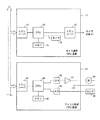
図2は,カメラ通信CPU基板11等の電気的構成を示すブロック図である。
FIG. 2 is a block diagram showing an electrical configuration of the camera
カメラ通信CPU基板11には,制御を統括するCPU(制御回路)70が実装されている。上述のようにRS232Cにもとづく通信とCAN通信とのプロトコル変換はCPU70によって行われる。CPU70にはタイマ73およびメモリ74が接続されている。
The camera
また,カメラ通信CPU基板11には,ネットワーク・ラインを介して他のCPU基板12−22とCAN通信するための第1のトランシーバ71およびカメラ本体41とRS232Cにもとづく通信をするための第2のトランシーバ72が含まれている。ネットワーク・ラインを介してCPU基板12−22から送信されたデータは第1のトランシーバ71において受信され,CPU70においてプロトコル変換が行われて第2のトランシーバ72からRS232Cケーブルを介してカメラ本体41に送信される。RS232Cケーブルを介してカメラ本体41から送信されたデータは第2のトランシーバ72において受信され,CPU70においてプロトコル変換が行われて第1のトランシーバ71からCPU基板12−22に送信される。
The camera
アイリス制御基板21にも制御を統括するCPU80が実装されている。CPU80にはメモリ85が接続されている。
The
アイリス制御基板21にも撮影ユニット・レンズ1内のCPU基板11−20,22とCAN通信するためのトランシーバ81が実装されている。アイリスの位置を示すデータがアイリス制御CPU基板21において受信されると,そのデータにもとづいてCPU80においてアイリス・モータ53の駆動データが生成される。生成された駆動データは,CPU80からディジタル/アナログ変換回路82においてアナログ駆動信号に変換される。変換されたアナログ駆動信号がドライバ83に与えられると,ドライバ83によってアイリス・モータ53が駆動させられる。また,アイリスの位置は位置センサ54によって検出される。位置センサ54からの検出信号はアナログ/ディジタル変換回路84においてディジタル位置データに変換されCPU80に入力する。
A
上述したように,バーチャル・システムCPU基板12,ズーム要求CPU基板19およびフォーカス要求CPU基板20は,カメラ通信CPU基板11と同じ構成であり,防振ユニットCPU基板13,PFユニットCPU基板14,ズーム制御CPU基板17,フォーカス制御CPU基板18およびエクステンダ制御CPU基板22は,アイリス制御CPU基板21と同じ構成である。スイッチ制御CPU基板15は,CPU,上述したようにネットワーク・ラインを介して通信するためのトランシーバ,スイッチ31,32等からの信号を入力しディジタル・データに変換するアナログ/ディジタル変換回路,メモリなどが実装されている。表示制御CPU基板16は,CPU,上述したようにネットワーク・ラインを介して通信するためのトランシーバ,CPUからのディジタル・データを変換し表示装置33,34などに表示制御信号を出力するディジタル/アナログ変換回路,メモリなどが実装されている。
As described above, the virtual
図3は,カメラ通信CPU基板11に実装されているメモリ74に記憶されている通信データ(状況データ)の一例である。
FIG. 3 is an example of communication data (situation data) stored in the memory 74 mounted on the camera
上述したように,この実施例では,撮影レンズ・ユニット1内のCPU基板11−22同士のデータ通信はCAN通信が利用される。CAN通信では,複数のCPU基板11−22が共通のネットワーク・ラインを利用するから,送信するデータに送信対象となるCPU基板11−22のIDが含まれる。CPU基板11−22がネットワーク・ライン上を通信しているデータを受信した場合に,受信したデータに自分のIDが含まれていれば,自分宛のデータであることが認識される。受信したデータにもとづく制御が行われる。
As described above, in this embodiment, CAN communication is used for data communication between the CPU boards 11-22 in the photographing
この実施例においては,カメラ通信CPU基板11は,ネットワーク・ライン上に通信されるすべてのデータを受信し,自分宛のデータとしてメモリ74に記憶する。カメラ通信CPU基板11は,撮影レンズ・ユニット1に含まれているCPU基板11−22のいずれかに送信されたデータを自分宛のデータとみなしてメモリ74に記憶する。カメラ本体41からのデータの要求があった場合に,その要求に応じたCPU基板にデータを転送することなく,メモリ74に記憶されているデータをカメラ本体41に送信できる。
In this embodiment, the camera
メモリ74には,カメラ通信CPU基板11においてネットワーク・ライン上を通信しており受信した通信データが,メモリ74に記憶された時間に対応して記憶されている。
In the memory 74, communication data received through the camera
たとえば,ある時間において,アイリス制御CPU基板21からアイリスの位置I1を示すデータがネットワーク・ライン上に送信されたとすると,そのアイリスの位置I1を示すデータがカメラ通信CPU基板11において受信され,メモリ74に記憶される。同様に,ある時間において,ズーム位置Z1,フォーカス位置F1などを示すデータがネットワーク・ライン上に送信されたとすると,それらのズーム位置Z1,フォーカス位置F1などを示すデータがメモリ74に記憶される。
For example, if data indicating the position I1 of the iris is transmitted from the iris
一定周期で,カメラ通信CPU基板11から他のCPU基板12−22にデータを要求し,その要求に応じて他のCPU基板12−22から送信されるデータを受信し,メモリ74に記憶するようにしてもよい。重複している種類のデータは最新のデータのみをメモリ74に残すようにデータの更新処理が行われる。
The camera
図4は,CAN通信においてデータを送信する転送フォーマットであるデータ・フレームの構造を示している。 FIG. 4 shows the structure of a data frame which is a transfer format for transmitting data in CAN communication.
データ・フレームは,リセッシブまたはドミナントのいずれかとなる。各部の数字はビット数を示している。また,通信が行われていない場合,バスはリセッシブとなっている(バス・アイドル)。 Data frames can be either recessive or dominant. The numbers in each part indicate the number of bits. When no communication is performed, the bus is recessive (bus idle).
データ・フレームには,スタート・オブ・フレーム,識別子フィールド,RTR,コントロール・フィールド,データ・フィールド,CRCシーケンス,CRCデリミタ,ACKスロット,ACKデリミタ,エンド・オブ・フレームが含まれ,その順で送信される。 The data frame includes a start of frame, an identifier field, an RTR, a control field, a data field, a CRC sequence, a CRC delimiter, an ACK slot, an ACK delimiter, and an end of frame. Is done.
スタート・オブ・フレームは,データ・フレームの開始を表わすものであり,ドミナント状態とされる。スタート・オブ・フレームがバス・アイドルのリセッシブからドミナントへ変化することにより受信側のCPU基板(受信ノード)は同期を行うことができる。 The start of frame represents the start of the data frame and is in a dominant state. The CPU board (receiving node) on the receiving side can perform synchronization by changing the start of frame from recessive in bus idle to dominant.
識別子フィールドは,データ内容や送信側のCPU基板(送信ノード)を識別するために使用される。受信側のCPU基板は,識別子フィールドに記述されている内容(上述したID)を検出することにより,自分が使用するデータ・フレームかどうかを判断できる。識別子フィールドは通信調停の優先順位を決定することもある。CPU制御基板11−22のうち,カメラ通信CPU基板11以外のCPU基板12−22は,識別フィールドに記述されている内容が自分宛のものであれば,自分宛のデータとして受信する。カメラ通信CPU基板11は,CPU基板11−22のいずれ宛のデータであっても,自分宛のデータとして受信し,上述のようにメモリ74にその内容を記憶する。
The identifier field is used to identify the data contents and the CPU board (transmission node) on the transmission side. The CPU board on the receiving side can determine whether or not it is a data frame used by itself by detecting the contents (ID described above) described in the identifier field. The identifier field may determine the priority of communication arbitration. Among the CPU control boards 11-22, the CPU boards 12-22 other than the camera
RTR(Remote Transmission Request )は,データを送信するデータ・フレームとデータの送信を要求するリモート・フレームとを識別するために使用される。データ・フレームの場合には,RTRはドミナントとなっている。RTRも識別子フィールドと同様に通信調停に使用される。 RTR (Remote Transmission Request) is used to identify a data frame for transmitting data and a remote frame for requesting data transmission. In the case of a data frame, the RTR is dominant. The RTR is also used for communication arbitration in the same manner as the identifier field.
コントロール・フィールドは,次のデータ・フィールド内で何バイト送信されるかを示すものである。 The control field indicates how many bytes are transmitted in the next data field.
データ・フィールドは,データ・フレームで送信されるデータの部分である。 The data field is the portion of data transmitted in the data frame.
CRC(Cyclic Redundancy Check )シーケンスは,データ送信時のデータ破壊をチェックするものである。 The CRC (Cyclic Redundancy Check) sequence is a check for data corruption during data transmission.
CRCデリミタは,CRCシーケンスの終了を表す区切り記号で,1ビット長のリセッシブ固定である。 The CRC delimiter is a delimiter that indicates the end of the CRC sequence, and is fixed to a recessive 1-bit length.
ACK(Acknowledgement)スロットは,正常受信確認のためのフィールドである。 An ACK (Acknowledgement) slot is a field for normal reception confirmation.
ACKデリミタは,ACKスロットの終了を表す区切り記号で、1ビット長のリセッシブ固定である。 The ACK delimiter is a delimiter representing the end of the ACK slot and is fixed to a recessive 1-bit length.
エンド・オブ・フレームは,送信または受信の終了を示すものであり,リセッシブ固定となっている。 The end-of-frame indicates the end of transmission or reception, and is fixed to recessive.
複数のCPU基板から同時にデータ・フレームが送信されてしまう場合,通信調停が行われる。たとえば,二つのデータ・フレームが送信された場合,それらの二つのデータ・フレームのそれぞれの識別子フィールドに記述されているデータ1ビットずつ比較され,最初に相違したデータがドミナントとなっていた方のデータ・フレームが優先して送信される。 When data frames are transmitted simultaneously from a plurality of CPU boards, communication arbitration is performed. For example, when two data frames are transmitted, one bit of data described in the identifier field of each of the two data frames is compared, and the first difference data becomes the dominant one. Data frames are transmitted with priority.
図5は,カメラ通信CPU基板11の処理手順を示すフローチャートである。
FIG. 5 is a flowchart showing a processing procedure of the camera
カメラ本体41が撮影レンズ・ユニット1に装着され,カメラ本体41から撮像レンズ・ユニット1に電源が供給される。すると,カメラ通信CPU基板11において初期設定が行われる(ステップ91)。
The
上述のように,カメラ通信CPU基板11は,撮影レンズ・ユニット1のネットワーク・ライン上のデータ通信を監視しており,CPU基板11−22宛のいずれのCPU基板に送信されるデータも受信し,メモリ74に記憶する(ステップ92)。
As described above, the camera
カメラ通信CPU基板11がカメラ本体41からのコマンドを正常に受信すると(ステップ93および94でいずれもYES),プロトコル変換/カメラ本体への返信処理が行われる(ステップ95)。このステップ95の処理は後述する。カメラ本体41からの電源の供給が停止し,撮影レンズ・ユニット1がオフとなるまでステップ92から95の処理が繰り返される(ステップ96)。
When the camera
図6および図7は,プロトコル変換/カメラ本体への返信処理手順(図5ステップ95の処理手順)を示すフローチャートである。
6 and 7 are flowcharts showing the protocol conversion / reply processing procedure to the camera body (the processing procedure of
カメラ本体41から送信されたコマンドが正常に受信されると,その受信したコマンドがコントロール・コマンド,アイリスなどの位置データの要求コマンド,その他のコマンドに分類される(図6ステップ101)。
When a command transmitted from the
カメラ本体41から送信されたデータがコントロール・コマンドであり,そのコントロール・コマンドがカメラ通信CPU基板11において受信されると(図6ステップ102でYES),アイリス,ズームまたはフォーカスのコントロール・コマンドを受信したかどうかが判定される(図6ステップ103)。
When the data transmitted from the
アイリス,ズームまたはフォーカスのコントロール・コマンドには,はアイリス,ズームまたはフォーカスの位置を指定する位置データが含まれている。カメラ通信CPU基板11が,アイリス,ズームまたはフォーカスのコントロール・コマンドを受信した場合には(図6ステップ103でYES),そのコントロール・コマンドに含まれている位置データは,カメラ本体41内でカメラ本体41用に生成されたものであり,撮影レンズ・ユニット1にそのまま適用できない。このために,カメラ本体41用に生成された位置データが撮影レンズ・ユニット1に適したものなるように位置データを変換する演算処理が行われる(図6ステップ104)。上述したようにカメラ本体41とカメラ通信CPU基板11との間はRS232Cにもとづく通信であるのに対し,撮影レンズ・ユニット1内はCAN通信であるので,演算された位置データがRS232Cケーブルにもとづく通信プロトコルからCAN通信プロトコルに変換も行われる。変換された位置データがアイリス制御CPU基板21,ズーム制御CPU基板17またはフォーカス制御CPU基板18に送信される(図6ステップ105)。
The iris, zoom or focus control command includes position data for specifying the position of the iris, zoom or focus. When the camera
アイリス制御CPU基板21,ズーム制御CPU基板17またはフォーカス制御CPU基板18のうち,カメラ通信CPU基板11から送信された位置データを受信したCPU基板21,17または18が,受信した位置データによって指定される位置となるようにアイリス,ズーム・レンズまたはフォーカス・レンズを制御することとなる。
Of the iris
カメラ通信CPU基板11において受信したコマンドがコントロール・コマンドではあるが(図6ステップ102でYES),アイリス,ズームまたはフォーカスのコントロール・コマンドではない場合(たとえば,エクステンダが倍率1または倍率2のいずれかの位置コントロールするコマンドの場合)には(図6ステップ103でNO),受信したデータがカメラ通信CPU基板11から対象となるCPU基板(たとえば,エクステンダ制御CPU基板20)に送信される(図6ステップ106)。対象となるCPU基板に送信されるデータは,CAN通信のプロトコルからRS232Cにもとづく通信プロトコルに変換されて送信されるのはいうまでもない。
If the command received by the camera
カメラ本体41から送信され,カメラ通信CPU基板11において受信しコマンドがコントロール・コマンドでなければ(図6ステップ102でNO),受信したコマンドがアイリス,ズームまたはフォーカスの要求コマンドかどうかが判定される(図7ステップ107)。
If the command transmitted from the
受信したコマンドがアイリス,ズームまたはフォーカスの要求コマンドであると(図7ステップ107でYES),カメラ通信CPU基板11のメモリ74に記憶されているデータのうち,要求されているデータが読み取られる。読み取られたデータは撮影レンズ・ユニット1内においてアイリス,ズームまたはフォーカスの位置を示すデータであるから,カメラ本体41での位置を示すデータとなるように演算される(図7ステップ108)。また,CAN通信のプロトコルからRS232Cケーブルにもとづく通信プロトコルに,その位置を示すデータが変換される。変換された位置データがカメラ通信CPU基板11からカメラ本体41に送信される(図7ステップ109)。
If the received command is an iris, zoom or focus request command (YES in
要求されているデータがカメラ通信CPU基板11のメモリ74に記憶されていない場合には,アイリス制御CPU基板21,ズーム制御CPU基板19またはフォーカス制御CPU基板18のうち,位置データが必要な基板にカメラ通信CPU基板11から要求コマンドが直接に送信される。また,カメラ通信CPU基板11のメモリ74に記憶されているデータの記憶時間が要求コマンドの受信から一定時間以上経過している場合には,アイリス,フォーカス,またはズームの位置が,メモリ74に記憶されているデータによって示される位置から代わっている可能性がある。そのような場合にもアイリス制御CPU基板21,ズーム制御CPU基板19またはフォーカス制御CPU基板18のうち,位置データが必要な基板にカメラ通信CPU基板11から要求コマンドが送信され,最新のデータが取得される。取得されたデータについての上記演算,プロトコル変換が行われるのはいうまでもない。
If the requested data is not stored in the memory 74 of the camera
カメラ通信CPU基板11において受信したコマンドがアイリス,ズームまたはフォーカスの位置データの要求コマンドでもない場合(たとえば,エクステンダが倍率1または倍率2のいずれの位置にあるかを認識するための要求コマンド)には(図7ステップ107でNO),カメラ通信CPU基板11のメモリ74から要求されたデータが読み取られる。読み取られたデータがカメラ通信CPU基板11からカメラ本体41に送信される(図7ステップ110)。
When the command received at the camera
上述の実施例では,カメラ本体41から送信されるコマンドは,カメラ通信CPU基板11からCPU基板12−22のうちのいずれか一つのCPU基板に送信されているが,二つ以上のCPU基板に送信されるようにしてもよい。二つ以上のCPU基板に送信するためには上述したようにCAN通信の識別子フィールドに送信対象の二つ以上のCPU基板のIDを記述すればよい。
In the above-described embodiment, the command transmitted from the
バーチャル・システムでは,実写映像とコンピュータ・グラフィック映像とが合成される。ズーム位置に応じてコンピュータ・グラフィック映像を小さくする必要がある。また,PFユニットCPU基板14においては,焦点距離が近いときには被写界深度が深く,ピントがあっているように見えるので,合焦制御を止めることがある。このために,ズーム位置を認識する必要がある。さらに,防振ユニットCPU基板13ではズーム位置に応じて補正度合いを変えることがあり,カメラ通信CPU基板11では上述のようにカメラ本体41からズーム位置の要求があった場合には,その要求に応じる必要がある。このように,たとえば,ズーム・レンズの位置データは,複数のCPU基板においてズーム位置データが必要となることがある。その場合には,複数のCPU基板宛にズーム位置データが送信されることとなる。
In the virtual system, live-action video and computer graphic video are synthesized. It is necessary to reduce the computer graphic image according to the zoom position. Further, in the PF
上述した実施例では,CAN通信が利用されているがCAN通信以外のネットワーク技術を利用してもよい。たとえば,PROFIBUS,CC-Link,Interbus,EC-NETなどを利用することもできる。 In the embodiment described above, CAN communication is used, but network technologies other than CAN communication may be used. For example, PROFIBUS, CC-Link, Interbus, EC-NET, etc. can be used.
上述した実施例では,CPU基板11−22がネットワーク・ラインにより接続されているが,これらのCPU基板11−22とネットワーク・ラインとはコネクタ等により着脱自在に接続される。 In the embodiment described above, the CPU board 11-22 is connected by a network line. However, the CPU board 11-22 and the network line are detachably connected by a connector or the like.
カメラ通信CPU基板11とバーチャル・システムCPU基板12とは同じ構成である。また,ズーム制御CPU基板17,フォーカス制御CPU基板18,アイリス制御CPU基板21およびエクステンダCPU基板22は同じ構成であり,基板の共通化が図られている。また,ズーム要求CPU基板19およびフォーカス要求CPU基板20はいずれもCPUが実装されており,ズーム要求信号またはフォーカス要求信号がアナログ/ディジタル変換回路を介してズーム要求CPU基板19またはフォーカス要求CPU基板20に実装されているCPUに入力する。さらに,スイッチ制御CPU基板15と表示制御CPU基板16も同じ構成であり,スイッチ31,32などから入力する信号がアナログ/ディジタル変換回路を介してスイッチ制御CPU基板15のCPUに入力し,表示制御CPU基板16のCPUからの制御データがディジタル/アナログ変換回路においてアナログ制御信号に変換されて表示装置33,34に入力する。さらに,PFユニットCPU基板14と防振ユニットCPU基板13との構成も同じである。
The camera
CPU制御基板51−64にはCPUおよびネットワーク・ラインを介して通信するための通信回路(トランシーバ)が共通に実装されているので,それらの回路についての共通化を図ることもできる。 Since the CPU control boards 51-64 are commonly mounted with a communication circuit (transceiver) for communicating via the CPU and the network line, the circuits can be shared.
1 撮影レンズ・ユニット
11 カメラ通信CPU基板(カメラ通信制御基板)
11−22 CPU基板
41 カメラ本体
70,80 CPU(制御回路)
1 Shooting lens unit
11 Camera communication CPU board (Camera communication control board)
11-22 CPU board
41 Camera body
70, 80 CPU (control circuit)
Claims (4)
上記複数の制御基板に含まれており,撮像装置と接続されるカメラ通信制御基板であって,撮像装置との通信に用いられる外部通信プロトコルと,ネットワーク・ラインを利用した撮影レンズ・ユニット内の制御基板との通信に用いられる内部通信プロトコルと,の間のプロトコル変換を行うカメラ通信制御基板,
を備えた撮影レンズ・ユニット。 A control circuit for controlling imaging by the imaging device is mounted on each of a plurality of independent control boards, and at least two or more control boards have the same structure, and the control boards are network lines. A plurality of control boards connected to each other, and a camera communication control board included in the plurality of control boards and connected to the imaging device, the external communication protocol used for communication with the imaging device, and a network・ Camera lens control board which performs protocol conversion between the internal communication protocol used for communication with the control board in the taking lens unit in the line,
Photographic lens unit with
撮像装置から外部通信プロトコルによって送信された制御信号を,内部通信プロトコルに変換し,内部通信プロトコルに変換された制御信号を上記複数の制御基板のうち,一または複数の制御基板に送信するものである,
請求項1に記載の撮影レンズ・ユニット。 The camera communication control board
The control signal transmitted from the imaging device by the external communication protocol is converted into the internal communication protocol, and the control signal converted into the internal communication protocol is transmitted to one or a plurality of control boards among the plurality of control boards. is there,
The photographic lens unit according to claim 1.
上記複数の制御基板のそれぞれが制御する制御対象の状況を表わす状況データを周期的に検出し,
検出された制御対象の状況を表わす状況データを記憶するメモリを備え,
撮像装置から送信された制御信号に応じて,上記メモリに記憶されている状況データを外部通信プロトコルによって撮像装置に送信するものである,
請求項1または2に記載の撮影レンズ・ユニット。 The camera communication control board
Periodically detecting status data representing the status of the controlled object controlled by each of the plurality of control boards,
A memory for storing status data representing the status of the detected control object;
According to the control signal transmitted from the imaging device, the status data stored in the memory is transmitted to the imaging device by an external communication protocol.
The taking lens unit according to claim 1 or 2.
上記複数の制御基板に含まれており,撮像装置と接続されるカメラ通信制御基板が,撮像装置との通信に用いられる外部通信プロトコルと,ネットワーク・ラインを利用した撮影レンズ・ユニット内の制御基板との通信に用いられる内部通信プロトコルと,の間のプロトコル変換を行う,
撮影レンズ・ユニットの動作制御方法。 A control circuit for controlling imaging by the imaging device is mounted on each of a plurality of independent control boards, and at least two or more control boards have the same structure, and the control boards are network lines. Provided with a plurality of control boards connected by
The camera communication control board, which is included in the plurality of control boards and connected to the image pickup apparatus, is an external communication protocol used for communication with the image pickup apparatus and a control board in the taking lens unit using the network line. Protocol conversion between internal communication protocol used for communication with
How to control the operation of the photographic lens unit.
Priority Applications (1)
| Application Number | Priority Date | Filing Date | Title |
|---|---|---|---|
| JP2011164946A JP5588940B2 (en) | 2011-07-28 | 2011-07-28 | Photographic lens unit and operation control method thereof |
Applications Claiming Priority (1)
| Application Number | Priority Date | Filing Date | Title |
|---|---|---|---|
| JP2011164946A JP5588940B2 (en) | 2011-07-28 | 2011-07-28 | Photographic lens unit and operation control method thereof |
Publications (2)
| Publication Number | Publication Date |
|---|---|
| JP2013030945A JP2013030945A (en) | 2013-02-07 |
| JP5588940B2 true JP5588940B2 (en) | 2014-09-10 |
Family
ID=47787570
Family Applications (1)
| Application Number | Title | Priority Date | Filing Date |
|---|---|---|---|
| JP2011164946A Active JP5588940B2 (en) | 2011-07-28 | 2011-07-28 | Photographic lens unit and operation control method thereof |
Country Status (1)
| Country | Link |
|---|---|
| JP (1) | JP5588940B2 (en) |
Families Citing this family (1)
| Publication number | Priority date | Publication date | Assignee | Title |
|---|---|---|---|---|
| KR20220087554A (en) * | 2019-12-02 | 2022-06-24 | 씨비씨 가부시끼가이샤 | lens device |
Family Cites Families (2)
| Publication number | Priority date | Publication date | Assignee | Title |
|---|---|---|---|---|
| JP4274671B2 (en) * | 2000-03-30 | 2009-06-10 | オリンパス株式会社 | Electronic camera and electronic camera system |
| US8521016B2 (en) * | 2008-03-28 | 2013-08-27 | Panasonic Corporation | Camera system |
-
2011
- 2011-07-28 JP JP2011164946A patent/JP5588940B2/en active Active
Also Published As
| Publication number | Publication date |
|---|---|
| JP2013030945A (en) | 2013-02-07 |
Similar Documents
| Publication | Publication Date | Title |
|---|---|---|
| JP7409623B2 (en) | Accessory devices, cameras, communication control programs, and camera systems | |
| US8351131B2 (en) | Lens apparatus | |
| US10911659B2 (en) | Accessory device, camera, and storage medium | |
| JP2022167999A (en) | Accessory device and imaging device | |
| US10942425B2 (en) | Accessory device, camera, and storage medium | |
| JP2020052182A (en) | Adapter device, camera system, method for control, and program | |
| JP5588940B2 (en) | Photographic lens unit and operation control method thereof | |
| JP5782517B2 (en) | Camera control system and operation control method thereof | |
| JP5618937B2 (en) | Photographic lens unit and operation control method thereof | |
| EP3705939B1 (en) | Camera, accessory device and control method thereof | |
| JP5542461B2 (en) | Vibration isolator | |
| JP2020034740A (en) | Imaging device, accessory, and program | |
| JP2006065068A (en) | Anti-vibration apparatus | |
| JP5723237B2 (en) | Photographic lens unit and operation control method thereof | |
| JP2019201337A (en) | Accessory device, camera system including the same, and program | |
| JP7171316B2 (en) | Accessories, cameras and communication control programs | |
| JP2018031942A (en) | Imaging apparatus, accessory device, imaging system, communication control method, and communication control program | |
| JP2013029666A (en) | Camera image blurring correction device and operation control method thereof | |
| JP2020034802A (en) | Accessory, camera, and communication control program | |
| JP2013029626A (en) | Lens/iris controller and operation control method therefor | |
| US20130038784A1 (en) | Lens apparatus and imaging system using the same |
Legal Events
| Date | Code | Title | Description |
|---|---|---|---|
| A621 | Written request for application examination |
Free format text: JAPANESE INTERMEDIATE CODE: A621 Effective date: 20131113 |
|
| A977 | Report on retrieval |
Free format text: JAPANESE INTERMEDIATE CODE: A971007 Effective date: 20140626 |
|
| TRDD | Decision of grant or rejection written | ||
| A01 | Written decision to grant a patent or to grant a registration (utility model) |
Free format text: JAPANESE INTERMEDIATE CODE: A01 Effective date: 20140701 |
|
| A61 | First payment of annual fees (during grant procedure) |
Free format text: JAPANESE INTERMEDIATE CODE: A61 Effective date: 20140728 |
|
| R150 | Certificate of patent or registration of utility model |
Ref document number: 5588940 Country of ref document: JP Free format text: JAPANESE INTERMEDIATE CODE: R150 |
|
| R250 | Receipt of annual fees |
Free format text: JAPANESE INTERMEDIATE CODE: R250 |
|
| R250 | Receipt of annual fees |
Free format text: JAPANESE INTERMEDIATE CODE: R250 |
|
| R250 | Receipt of annual fees |
Free format text: JAPANESE INTERMEDIATE CODE: R250 |
|
| R250 | Receipt of annual fees |
Free format text: JAPANESE INTERMEDIATE CODE: R250 |
|
| R250 | Receipt of annual fees |
Free format text: JAPANESE INTERMEDIATE CODE: R250 |
|
| R250 | Receipt of annual fees |
Free format text: JAPANESE INTERMEDIATE CODE: R250 |
|
| R250 | Receipt of annual fees |
Free format text: JAPANESE INTERMEDIATE CODE: R250 |
|
| R250 | Receipt of annual fees |
Free format text: JAPANESE INTERMEDIATE CODE: R250 |