JP5542461B2 - Vibration isolator - Google Patents
Vibration isolator Download PDFInfo
- Publication number
- JP5542461B2 JP5542461B2 JP2010014486A JP2010014486A JP5542461B2 JP 5542461 B2 JP5542461 B2 JP 5542461B2 JP 2010014486 A JP2010014486 A JP 2010014486A JP 2010014486 A JP2010014486 A JP 2010014486A JP 5542461 B2 JP5542461 B2 JP 5542461B2
- Authority
- JP
- Japan
- Prior art keywords
- signal
- serial
- camera
- parallel
- communication
- Prior art date
- Legal status (The legal status is an assumption and is not a legal conclusion. Google has not performed a legal analysis and makes no representation as to the accuracy of the status listed.)
- Expired - Fee Related
Links
Images


Description
本発明は防振装置に係り、特にカメラとレンズ装置の間に装着されるアダプタ式の防振装置に関する。 The present invention relates to a vibration isolator, and more particularly, to an adapter type vibration isolator mounted between a camera and a lens device.
テレビカメラの防振装置として、レンズ装置に内蔵されているものと、レンズ装置に外付けされるアダプタ式のものとが知られている。アダプタ式の防振装置は、防振装置が組み込まれていないレンズ装置を使用する場合であっても防振機能を追加することができ、また、多種のレンズ装置で共用することができるためレンズ装置に防振装置を組み込む場合に比べてコスト的に有利な面がある。 As an anti-vibration device for a television camera, a built-in lens device and an adapter-type device externally attached to the lens device are known. The adapter type anti-vibration device can add an anti-vibration function even when using a lens device that does not incorporate the anti-vibration device, and can be shared by various lens devices. There is an advantage in terms of cost as compared with the case where a vibration isolator is incorporated in the apparatus.
アダプタ式の防振装置は、例えば、レンズ装置とカメラ(カメラ本体)との間に着脱可能に装着されるようになっており、レンズ装置の撮影光学系(撮影レンズ)の後端側に配置される補正レンズ、振動を検出する振れ検出センサ(ジャイロセンサ等)、補正レンズを光軸に対して直交方向に駆動制御する制御部等を備えている。制御部は、振れ検出センサによって検出した振動に基づいてその振動に起因して生じる像振れを打ち消すように補正レンズの変位量を制御している。 The adapter type vibration isolator is, for example, detachably mounted between the lens device and the camera (camera body), and is disposed on the rear end side of the lens optical imaging system (photographing lens). A correction lens, a shake detection sensor (such as a gyro sensor) that detects vibration, and a control unit that drives and controls the correction lens in a direction orthogonal to the optical axis. The control unit controls the displacement amount of the correction lens based on the vibration detected by the shake detection sensor so as to cancel the image shake caused by the vibration.
ところで、防振装置において、振れ検出センサによって検出した振動の大きさに対して、その振動に起因して生じる像振れの大きさが撮影光学系の状態や特性等によって異なるため、精度の高い防振制御(像ブレ補正)を行うためには、撮影光学系の状態(ズームやエクステンダー等の位置情報)や特性等に関するレンズ情報を取得し、レンズ情報を考慮して防振制御を行う必要がある。 By the way, in the vibration isolator, the magnitude of the image shake caused by the vibration detected by the shake detection sensor differs depending on the state and characteristics of the photographing optical system. In order to perform vibration control (image blur correction), it is necessary to acquire lens information related to the state of the photographing optical system (position information such as zoom and extender) and characteristics, and to perform image stabilization control in consideration of the lens information. is there.
従来、特許文献1では、カメラとレンズ装置との間でアナログのパラレル信号(パラレル方式の通信)でやり取りされるレンズ情報を防振装置で抜き出して取得することが提案されている。
Conventionally, in
また、近年では、カメラとレンズ装置との間でシリアル通信(シリアル方式の通信)によりレンズ情報や制御信号を送受信するものがあり、その場合には特許文献1の防振装置ではレンズ情報を取得することができない。そこで、特許文献2の防振装置では、レンズ装置との間でシリアル通信(シリアル方式の通信)を行うことによりレンズ情報を取得できるようにするとともに、パラレル信号では得ることのできない撮影光学系の特性に関する情報(特性を特定するためのレンズ名称等)を含めたレンズ情報を取得することが提案されている。
Further, in recent years, there is a camera that transmits and receives lens information and control signals by serial communication (serial communication) between the camera and the lens apparatus. In this case, the vibration isolator disclosed in
しかしながら、レンズ装置によってはシリアル通信を行う機能を有していないものがあり、特許文献2の防振装置のようにレンズ装置との間のシリアル通信によりレンズ情報を取得するものとすると、シリアル通信機能を有していないレンズ装置に対しては使用できないか、又は、レンズ情報を全く考慮しない精度の低い防振制御しか行うことができないという問題があった。
However, some lens devices do not have a function of performing serial communication. If the lens information is acquired by serial communication with the lens device as in the vibration isolator of
本発明はこのような事情に鑑みてなされたもので、シリアル方式とパラレル方式のいずれか一方、又は、両方の通信機能を有しているいずれのタイプのレンズ装置に対してもレンズ装置からレンズ情報を取得して、精度の高い防振制御を行うことができる防振装置を提供することを目的とする。 The present invention has been made in view of such circumstances, and the lens device to the lens for any type of lens device having a communication function of either the serial method or the parallel method or both. An object of the present invention is to provide a vibration isolator capable of acquiring information and performing highly accurate vibration isolation control.
前記目的を達成するために、請求項1に記載の防振装置は、カメラとレンズ装置との間に着脱可能に配置される防振装置であって、振動による像振れを光学的に防止する防振装置において、前記カメラと前記レンズ装置との間で通信を行うために前記カメラ及び前記レンズ装置に設けられたコネクタの間を接続する信号線と、前記カメラと前記レンズ装置との間の通信方式が、パラレル方式とシリアル方式のうちのいずれの方式かを判定する通信方式判別手段と、前記信号線のうち、シリアル方式の通信においてシリアル信号が伝送される信号線から分岐されたシリアル信号検出線と、前記信号線のうち、パラレル方式の通信においてパラレル信号が伝送される信号線から分岐されたパラレル信号検出線と、前記通信方式判別手段によりシリアル方式と判定された場合には、前記シリアル信号検出線から防振制御に使用するレンズ情報を取得するシリアル信号取得手段と、前記通信方式判別手段によりパラレル方式と判定された場合には、前記パラレル信号検出線から防振制御に使用するレンズ情報を取得するパラレル信号取得手段と、を備えたことを特徴としている。
また、請求項2に記載の防振装置は、カメラとレンズ装置との間に着脱可能に配置される防振装置であって、振動による像振れを光学的に防止する防振装置において、前記カメラと前記レンズ装置との間で通信を行うために前記カメラ及び前記レンズ装置に設けられたコネクタの間を接続する信号線と、前記カメラと前記レンズ装置との間の通信方式が、パラレル方式とシリアル方式のうちのいずれの方式かを判定する通信方式判別手段と、前記信号線のうち、シリアル方式の通信においてシリアル信号が伝送される信号線におけるシリアル信号の伝送を中継し、かつ、シリアル信号から防振制御に使用するレンズ情報を取得するシリアル信号取得手段と、シリアル方式の通信においてシリアル信号が伝送される信号線に設けられるスイッチであって、前記通信方式判別手段によりパラレル方式と判定された場合には、前記レンズ装置のコネクタからの信号線を前記カメラのコネクタからの信号線に直結した状態に設定し、前記通信方式判別手段によりシリアル方式と判定された場合には、前記レンズ装置のコネクタからの信号線を前記シリアル信号取得手段を介して前記カメラのコネクタからの信号線に接続した状態に設定して、シリアル信号取得手段により前記レンズ情報を取得させるスイッチと、前記通信方式判別手段によりパラレル方式と判定された場合には、前記信号線のうち、パラレル方式の通信においてパラレル信号が伝送される信号線から防振制御に使用するレンズ情報を取得するパラレル信号取得手段と、を備えたことを特徴としている。
In order to achieve the above object, a vibration isolator according to
According to a second aspect of the present invention, there is provided a vibration isolator that is detachably disposed between the camera and the lens device, wherein the image stabilizer optically prevents image blur due to vibration. In order to communicate between the camera and the lens device, a signal line connecting between the camera and the connector provided in the lens device, and a communication method between the camera and the lens device is a parallel method. And a communication method discriminating means for determining which of the serial method and the serial signal transmission in the signal line through which the serial signal is transmitted in the serial communication among the signal lines, and the serial Serial signal acquisition means for acquiring lens information used for image stabilization control from a signal, and a switch provided on a signal line through which the serial signal is transmitted in serial communication If the communication method determining means determines that the parallel method is used, the signal line from the connector of the lens device is set to a state directly connected to the signal line from the connector of the camera, and the communication method determining means If the signal is determined to be a serial method, the signal line from the connector of the lens device is set to be connected to the signal line from the connector of the camera via the serial signal acquisition unit, and the serial signal acquisition unit If the switch is used to acquire the lens information by the communication method and the communication method determination means determines that the parallel method is used, the signal line from which the parallel signal is transmitted in the communication of the parallel method among the signal lines is controlled. And parallel signal acquisition means for acquiring lens information to be used.
本発明によれば、レンズ装置がカメラとの間でパラレル方式とシリアル方式のいずれの方式で通信を行うものであっても、防振制御に使用するレンズ情報をそれらの通信の信号線から取得することができる。従って、レンズ装置が、シリアル方式とパラレル方式のいずれか一方、又は、両方の通信機能を有しているいずれのタイプのものであっても防振制御に使用するレンズ情報を取得して精度の高い防振制御を行うことができる。 According to the present invention, even if the lens device communicates with the camera by either the parallel method or the serial method, the lens information used for the image stabilization control is acquired from the signal line of the communication. can do. Therefore, even if the lens device is of any type having either a serial method or a parallel method, or both, the lens information used for the image stabilization control is acquired and the accuracy is improved. High anti-vibration control can be performed.
請求項3に記載の防振装置は、請求項1又は2に記載の発明において、前記通信方式判別手段は、前記シリアル方式の通信においてシリアル信号が伝送される信号線を伝送する信号の単位時間当たりのパルス数を測定し、該測定したパルス数が所定の閾値以上の場合にはシリアル方式と判定し、該測定したパルス数が前記閾値未満の場合にはパラレル方式と判定する通信方式自動判別手段を備えたことを特徴としている。 According to a third aspect of the present invention, there is provided the vibration isolator according to the first or second aspect , wherein the communication method determining means is a unit time of a signal transmitted through a signal line through which a serial signal is transmitted in the serial communication. Automatic determination of communication method by measuring the number of pulses per unit and determining the serial method when the measured number of pulses is greater than or equal to a predetermined threshold and determining the parallel method when the measured number of pulses is less than the threshold It is characterized by having means.
本発明は、カメラとレンズ装置との間の通信方式を自動で判別するための態様である。 The present invention is an aspect for automatically discriminating a communication method between a camera and a lens apparatus.
請求項4に記載の防振装置は、請求項3に記載の発明において、前記カメラと前記レンズ装置との間の通信方式がパラレル方式とシリアル方式のうちのいずれの方式かをユーザが指定する通信方式指定手段を備え、前記通信方式自動判別手段の代わりに前記カメラと前記レンズ装置との間の通信方式が前記通信方式指定手段により指定された方式であると判定することを特徴としている。 According to a fourth aspect of the present invention, in the invention according to the third aspect, the user specifies whether the communication method between the camera and the lens device is a parallel method or a serial method. A communication system designating unit is provided, and instead of the communication system automatic discrimination unit, it is determined that the communication system between the camera and the lens apparatus is a system designated by the communication system designating unit.
本発明は、カメラとレンズ装置との間の通信方式を自動で判別するのみであると、その判別に誤りが生じる場合があるため、ユーザが手動で通信方式を指定できるようにした態様である。 The present invention is an aspect in which a user can manually specify a communication method because an error may occur in the determination only when the communication method between the camera and the lens apparatus is automatically determined. .
請求項5に記載の防振装置は、カメラとレンズ装置との間に着脱可能に配置される防振装置であって、振動による像振れを光学的に防止する防振装置において、前記カメラと前記レンズ装置との間で通信を行うために前記カメラ及び前記レンズ装置に設けられたコネクタの間を接続する信号線と、前記カメラ及び前記レンズ装置の各々の通信方式が、パラレル方式とシリアル方式のうちのいずれの方式かを判定する通信方式判別手段と、前記通信方式判別手段により前記レンズ装置の通信方式がシリアル方式と判定された場合には、前記信号線のうち、シリアル方式の通信において前記カメラへのシリアル信号の伝送に使用される信号線から前記レンズ装置からのシリアル信号を取得して防振制御に使用するレンズ情報を取得するシリアル信号取得手段と、前記通信方式判別手段により前記レンズ装置の通信方式がシリアル方式と判定された場合において、前記通信方式判別手段により前記カメラの通信方式がパラレル方式と判定された場合には、前記シリアル信号取得手段により取得された前記レンズ装置からのシリアル信号をパラレル信号に変換してパラレル方式の通信において前記カメラへのパラレル信号の伝送に使用される信号線に出力すると共に、パラレル方式の通信において前記レンズ装置へのパラレル信号の伝送に使用される信号線から前記カメラからのパラレル信号を取得し、該取得したパラレル信号をシリアル信号に変換してシリアル方式の通信において前記レンズ装置へのシリアル信号の伝送に使用される信号線に出力する第1の信号変換手段と、前記通信方式判別手段により前記レンズ装置の通信方式がパラレル方式と判別された場合には、前記信号線のうち、パラレル方式の通信において前記カメラへのパラレル信号の伝送に使用される信号線から前記レンズ装置からのパラレル信号を取得して防振制御に使用するレンズ情報を取得するパラレル信号取得手段と、前記通信方式判別手段により前記レンズ装置の通信方式がパラレル方式と判別された場合において、前記通信方式判別手段により前記カメラの通信方式がシリアル方式と判別された場合には、前記パラレル信号取得手段により取得された前記レンズ装置からのパラレル信号をシリアル信号に変換してシリアル方式の通信において前記カメラへのシリアル信号の伝送に使用される信号線に出力すると共に、シリアル方式の通信において前記レンズ装置へのシリアル信号の伝送に使用される信号線から前記カメラからのシリアル信号を取得し、該取得したシリアル信号をパラレル信号に変換してパラレル方式の通信において前記レンズ装置へのパラレル信号の伝送に使用される信号線に出力する第2の信号変換手段と、を備えたことを特徴としている。 The vibration isolator according to claim 5 is a vibration isolator that is detachably disposed between the camera and the lens device, wherein the camera is optically prevented from image blur due to vibration. In order to communicate with the lens device, a signal line connecting between the camera and a connector provided in the lens device, and a communication method of each of the camera and the lens device are a parallel method and a serial method. Communication method determination means for determining which of the above-mentioned methods, and when the communication method determination means determines that the communication method of the lens device is a serial method, among the signal lines, in the communication of the serial method A serial signal for acquiring lens information used for image stabilization control by acquiring a serial signal from the lens device from a signal line used for transmission of a serial signal to the camera. When the communication method of the lens apparatus is determined to be a serial method by the acquisition unit and the communication method determination unit, and the communication method of the camera is determined to be a parallel method by the communication method determination unit, the serial In the parallel communication, the serial signal from the lens device acquired by the signal acquisition means is converted into a parallel signal and output to a signal line used for the transmission of the parallel signal to the camera in the parallel communication. A parallel signal from the camera is acquired from a signal line used for transmission of a parallel signal to the lens device, the acquired parallel signal is converted into a serial signal, and the serial signal to the lens device in serial communication First signal converting means for outputting to a signal line used for transmission, and the communication method When the communication method of the lens device is determined to be a parallel method by the determination means, from the signal device, the signal line used for transmission of the parallel signal to the camera in the communication of the parallel method from the lens device. A parallel signal acquisition means for acquiring lens information used for image stabilization control by acquiring a parallel signal of the lens apparatus, and the communication method determination when the communication method of the lens apparatus is determined to be a parallel method by the communication method determination means When the communication method of the camera is determined to be a serial method by the means, the parallel signal from the lens device acquired by the parallel signal acquisition means is converted into a serial signal, and the camera is connected to the camera in serial communication. In addition to outputting to the signal line used for serial signal transmission, A serial signal from the camera is acquired from a signal line used for transmission of the serial signal to the lens device, the acquired serial signal is converted into a parallel signal, and the parallel signal to the lens device in parallel communication is acquired. And a second signal conversion means for outputting to a signal line used for transmission of the signal.
本発明によれば、請求項1に係る発明と同様に、レンズ装置がカメラとの間でパラレル方式とシリアル方式のいずれの方式で通信を行うものであっても、防振制御に使用するレンズ情報をそれらの通信の信号線から取得することができる。従って、レンズ装置が、シリアル方式とパラレル方式のいずれか一方、又は、両方の通信機能を有しているいずれのタイプのものであっても防振制御に使用するレンズ情報を取得して精度の高い防振制御を行うことができる。また、カメラとレンズ装置とが異なる通信方式での通信を行う設定が可能となり、例えば、レンズ装置がシリアル方式の通信のみ可能でカメラがパラレル方式の通信のみが可能な場合であっても本発明の防振装置を使用することでカメラとレンズ装置との間の通信が可能となる。また、カメラとレンズ装置との間でシリアル方式の通信が可能な場合であっても意図的に一方の通信方式をパラレル方式として、パラレル方式の通信によりアイリス等の動作が滑らかになる等の優位性がある場合にその優位性を生かした使用が可能となる。
According to the present invention, as in the invention according to
本発明に係る防振装置によれば、シリアル方式とパラレル方式のいずれか一方、又は、両方の通信機能を有しているいずれのタイプのレンズ装置に対してもレンズ装置からレンズ情報を取得して、精度の高い防振制御を行うことができる。 According to the vibration isolator of the present invention, lens information is acquired from the lens device for any type of lens device having a communication function of either the serial method or the parallel method, or both. Thus, it is possible to perform highly accurate vibration control.
以下添付図面に従って本発明に係る防振装置の好ましい実施の形態について詳述する。 A preferred embodiment of a vibration isolator according to the present invention will be described in detail below with reference to the accompanying drawings.
図1は、本発明に係る防振装置が適用されたテレビカメラ装置10の実施の形態を示した全体図である。
FIG. 1 is an overall view showing an embodiment of a
同図に示すテレビカメラ装置10は、三脚12の雲台14上に衝立状のレンズサポータ16が固定されており、そのレンズサポータ16のマウント枠17に対して図中右側にENGカメラ(以下、単にカメラという)18が設置され、マウント枠17に対して図中左側にマウント枠17に支持されたEFP用のレンズ装置22が配置されている。また、カメラ18とレンズ装置22の間には、マウント枠17に固定されたアダプタ式の防振装置20が配置されている。
In the
マウント枠17には開口部が形成されており、レンズ装置22後端のレンズマウントは、その開口部を貫通して防振装置20の前面側に設けられた化粧環内に挿入配置されている。また、防振装置20の後面側にはレンズ装置22のレンズマウントと同一のマウントが設けられており、そのマウントがカメラ18のマウント19に連結されている。これにより、カメラ18とレンズ装置22とが防振装置20を介して連結される。
An opening is formed in the
また、カメラ18、防振装置20、及び、レンズ装置22は、電気的にも接続されており、例えば、カメラ18とレンズ装置22との間(カメラ・レンズ間)での情報のやり取りは、防振装置20を介して行われるようになっている。図2は、図1のように連結されるカメラ18、防振装置20、及び、レンズ装置22を簡易的に示した図であり、同図のカメラ18及びレンズ装置22は、防振装置20の不使用時にカメラ18とレンズ装置22とを直接連結した場合に、ケーブルを使用することなくカメラ18のコネクタ18Aとレンズ装置22のコネクタ22Aとが直接接続されるようになっている。
Further, the
このようなカメラ18とレンズ装置22の間に配置される防振装置20では、例えば、後面側と前面側にそれぞれカメラ側コネクタ20Aとレンズ側コネクタ20Bとが設けられている。カメラ18とレンズ装置22との間に防振装置20を連結した際にカメラ側コネクタ20Aとカメラ18のコネクタ18Aとがケーブルを用いることなく直接接続されると共に、レンズ側コネクタ20Bとレンズ装置22のコネクタ22Aがケーブルを用いることなく直接接続され、カメラ・レンズ間の情報のやり取りが防振装置20を介して行われるようになっている。尚、カメラ18と防振装置20の間、レンズ装置22と防振装置20の間、及び、カメラ18とレンズ装置22との間での信号の伝送はどのような接続態様によって行われるものでもよく、図2のようにケーブルを使用しない態様であってもよいし、ケーブルで接続する態様であってもよい。
In such a
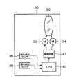
図3は、防振装置20の内部構成を示したブロック図である。上記レンズ装置22の撮影光学系(撮影レンズ)の光軸とカメラ18の光学系の光軸とは一致しており、同図において防振装置20に配置された補正レンズ30は、その光軸上に配置されると共に、光軸に対して直交する面内で上下(垂直)方向及び左右(水平)方向に移動可能に配置されている。また、補正レンズ30は、各モータ32、34によって垂直方向と水平方向とに駆動されるようになっている。
FIG. 3 is a block diagram showing the internal configuration of the
同図の振れ検出センサ36、38は、例えばジャイロセンサ等の角速度センサであり、振れ検出センサ36からは垂直方向に生じた振動に応じた振れ信号が出力され、振れ検出センサ38からは水平方向に生じた振動に応じた振れ信号が出力される。
The
防振装置20内にはCPU40が搭載されており、そのCPU40は振れ検出センサ36、38から得られる振れ信号に基づいて、垂直方向及び水平方向に生じた振動の向きと大きさ(振れ量)を検出し、その振動に起因する像振れを打ち消すための補正レンズ30の基準位置からの変位量を算出する。そして、駆動回路42に制御信号を出力してモータ32及びモータ34を駆動することによって、算出した変位量となるように補正レンズ30を変位させる。このような防振装置20での防振制御の処理により撮影光学系に生じた振動に対する像振れが防止される。
A
また、詳細は省略するが、防振装置20のCPU40は、レンズ装置22から撮影光学系の設定状態や特性に関するレンズ情報を取得し、そのレンズ情報を考慮して補正レンズ30の変位量を算出している。すなわち、像振れを完全に打ち消すための補正レンズ30の変位量を算出するためには、撮影光学系の設定状態としてズーム、エクステンダー、フォーカス、アイリス等の可動の光学要素の設定位置を考慮する必要があり、また、撮影光学系の特性として撮影光学系のズーム、エクステンダー等によって変更可能な焦点距離の可変範囲などのレンズ装置の機種に応じて異なる固有の特性を考慮する必要がある。撮影光学系の特性に関する情報(特性データ)は、各種レンズ装置に対応した特性データが事前にCPU40で読取可能なメモリに記憶され、実際に使用されるレンズ装置22からレンズ名称等の種類を特定する情報を取得することによって、レンズ装置22の種類に対応する特性データがメモリから読み出されて使用されるようになっている。尚、防振制御に使用するレンズ情報のうちレンズ装置22から取得できない情報については、ユーザが直接入力するなどの他の方法によって取得するか、または、標準値を使用して防振制御を行うようにしている。
Although not described in detail, the
続いて、防振装置20での防振制御に必要な情報の取得に関して説明する。図4は、カメラ18、防振装置20、レンズ装置22の間で各種情報をやり取りするための第1の実施の形態の構成を示したブロック図である。
Next, acquisition of information necessary for the image stabilization control by the
同図に示すように、カメラ18とレンズ装置22は、それらの間で各種情報を送受信するための信号入出力回路50、60を備えると共に、それらの信号入出力回路50、60の間で送受信される信号を伝送する信号線を接続するためのコネクタ18A、22Aを備えている。
As shown in the figure, the
信号入出力回路50、60は、カメラ18及びレンズ装置22がアナログのパラレル信号によって各種情報のやり取りを行うパラレル方式を採用するものである場合には、各信号線により伝送されるアナログの電圧信号を入出力する回路を示し、カメラ18及びレンズ装置22がシリアル通信によって各種情報のやり取りを行うシリアル方式を採用するものである場合には、所定の信号線により伝送されるシリアル信号(パルス信号)を入出力する回路を示している。
The signal input /
コネクタ18A、22Aには、カメラ18及びレンズ装置22が通信方式としてパラレル方式とシリアル方式のいずれを採用するものであっても同一規格のものが使用されており、例えば36ピンのコネクタが使用され、カメラ18の信号入出力回路50とレンズ装置22の信号入出力回路60との間が36本の信号線により接続されるようになっている.ただし、コネクタ18A、22Aのピン及び信号線の数はこれに限らない。また、図4では一部の信号線のみが示されている。
As the
一方、防振装置20は、カメラ18のコネクタ18Aに接続されるカメラ側コネクタ20Aと、レンズ装置22のコネクタ22Aに接続されるレンズ側コネクタ20Bを備え、それらのコネクタ20A、20Bとの間の対応するピン同士が防振装置20の内部の信号線により接続されている。
On the other hand, the
従って、カメラ18とレンズ装置22との間に防振装置20を介在させた場合であってもカメラ18のコネクタ18Aとレンズ装置22のコネクタ22Aとを直接接続した場合と同じ結線状態が保たれており、カメラ18とレンズ装置22との間の各種情報のやり取りが防振装置20の有無に関係なく正常に行われるようになっている。
Therefore, even when the
また、防振装置20は、図3でも示したように補正レンズ30を制御するためのCPU40を備えると共に、パラレル信号取込回路70と、シリアル信号取込回路72とを有している。
Further, as shown in FIG. 3, the
カメラ側コネクタ20Aとレンズ側コネクタ20Bの間を接続する全ての信号線には、信号検出用の検出線が分岐されて設けられており、パラレル信号取込回路70には、それらの検出線を通じて各信号線を伝送するアナログのパラレル信号が取り込まれるようになっている。そして、パラレル信号取込回路70に取り込まれたアナログのパラレル信号がCPU40で読取可能なデジタル信号に変換(A/D変換)された後、CPU40に与えられるようになっている。尚、パラレル方式の通信において使用される信号線が一部の信号線に限られる場合や防振制御に使用する情報が伝送される信号線が一部の信号線に限られる場合には、検出線もその信号線のみに設けるようにすれば良い。
All signal lines connecting between the camera-
また、コネクタ20Aとコネクタ20Bの間(コネクタ18Aとコネクタ22Aの間)を接続する信号線のうち、シリアル方式でのシリアル信号の伝送に使用される信号線(シリアル信号線LS)が決められており、そのシリアル信号線LSに信号検出用の検出線が分岐されて設けられている。例えば、パラレル方式においてエクステンダーの設定位置を示す電圧信号が伝送される信号線がシリアル信号線LSとして使用される。尚、シリアル信号線LSは一本ではなく複数本が該当する場合もあり、その場合において図4のシリアル信号線LSはいずれか1本のシリアル信号線を示しているものとする。
Of the signal lines connecting between the
そして、シリアル信号取込回路72には、その検出線を通じてシリアル信号が取り込まれ、通信制御のための信号が取り除かれてシリアル信号の通信内容のデータがCPU40に与えられるようになっている。
The serial
ここで、カメラ18とレンズ装置22との間でパラレル方式とシリアル方式のいずれの通信方式で通信が行われるかは、カメラ18とレンズ装置22との間で可能な通信方式により決定される。例えば、カメラ18とレンズ装置22の双方がシリアル方式と、アナログ方式のいずれか一方の通信方式のみ可能な場合にはその通信方式で通信が行われ、両方の通信方式が可能な場合には予め決められた優先される通信方式、又は、ユーザが選択した通信方式で通信が行われる。
Here, whether the communication method between the
これに対して、防振装置20のシリアル信号取込回路72は、処理開始時、又は、所定期間おきに、シリアル信号線LSから取り込まれる信号の単位時間当たりのパルス数を測定し、もし、そのパルス数が所定の閾値以上の場合には、カメラ18とレンズ装置22との間でシリアル方式の通信が行われていると判断し、取り込んだシリアル信号の通信内容のデータをCPU40に与える。
On the other hand, the serial
一方、測定したパルス数が所定の閾値未満の場合には、カメラ18とレンズ装置22との間でパラレル方式の通信が行われていると判断し、CPU40には何もデータを与えないようにしている。
On the other hand, if the measured number of pulses is less than the predetermined threshold value, it is determined that parallel communication is being performed between the
CPU40は、シリアル信号取込回路72からシリアル信号の通信内容のデータが与えられた場合(何らかのデータが与えられた場合)には、そのデータを有効なものとして取得し、パラレル信号取込回路70から与えられるデータを無効なものとする。
When the data of the communication content of the serial signal is given from the serial signal take-in circuit 72 (when some data is given), the
一方、シリアル信号取込回路72から何もデータが与えられない場合には、パラレル信号取込回路70から与えられるデータを有効なものとして取り込む。
On the other hand, when no data is given from the serial signal fetch
このようにして、カメラ18とレンズ装置22との間の通信方式が自動で判別され、それに応じてCPU40における情報の取込先が自動で切り換えられるようになっている。尚、シリアル信号取込回路72は、上記のようにパルス数によって通信方式を判別した後、その結果情報をCPU40に与えることによってCPU40での情報の取込先を切り換えるようにしてもよい。
In this way, the communication method between the
また、上記のようにカメラ18とレンズ装置22との間の通信方式の判別を自動で行うようにすると、誤りが生じる場合があるため、ユーザがカメラ18とレンズ装置22との間の通信方式を手動で指定するためのモードスイッチ84が設けられている。モードスイッチ84は、自動判別モード、シリアルモード、パラレルモードの3つのモードのうちからいずれかを選択することができるようになっている。自動判別モードが選択された場合、CPU40は、上記のようにシリアル信号取込回路72による通信方式の自動判別の結果に従い、情報の取込先をパラレル信号取込回路70とシリアル信号取込回路72のいずれかに切り替える。
In addition, if the determination of the communication method between the
シリアルモードが選択された場合には、カメラ18とレンズ装置22との間の通信方式がシリアル方式であるとして、情報の取込先をシリアル信号取込回路72に設定する。パラレルモードが選択された場合には、カメラ18とレンズ装置22との間の通信方式がパラレル方式であるとして、情報の取込先をパラレル信号取込回路70に設定するようになっている。
When the serial mode is selected, it is assumed that the communication method between the
また、カメラ18とレンズ装置22との間で、パラレル方式の通信が行われている場合、主に、レンズ装置22における撮影光学系のズーム、フォーカス、アイリス、エクステンダーの現在の設定状態(設定位置)を示す位置情報が電圧値(2〜7V)に対応させて各々異なる信号線を通じてレンズ装置22からカメラ18に送信されるようになっている。そして、CPU40は、パラレル信号取込回路70からこれらの情報をリアルタイムに取得している。
Further, when parallel communication is performed between the
同様に、カメラ18とレンズ装置22との間で、シリアル方式の通信が行われている場合、パラレル方式と同じように撮影光学系の現在の設定状態を示す位置情報がシリアル信号線LSを通じてレンズ装置22からカメラ18に送信され、CPU40は、シリアル信号取込回路72からこれらの情報をリアルタイムに取得している。一方、シリアル方式で通信が行われる場合、パラレル方式では送信されない情報もレンズ装置22からカメラ18に送信することが可能であり、例えば、通信開始時等において、レンズ装置22のレンズ名称、焦点距離の可変範囲等の撮影光学系の特性を示す特性情報(特性を特定するための情報も含む)が送信される場合がある。シリアル方式の通信が行われている場合にはCPU40は防振制御に使用するこのような特性情報も取得している。もし、シリアル方式の場合であってもカメラ18がそれらの情報を要求しない場合などには、CPU40もそれらの情報を取得することができないが、シリアル信号取込回路72にシリアル通信を行う機能を備えるようにすれば、カメラ18が要求する情報とは無関係にレンズ装置22から所望の情報をCPU40が取得することも可能である。例えば、カメラ18とレンズ装置22との間の通信が開始される前に、防振装置20のシリアル信号取込回路72とレンズ装置22(信号入出力回路60)との間でシリアル通信を開始し、レンズ装置22の特性情報を取得しておくことが可能である。カメラ18とレンズ装置22との間でパラレル方式の通信が行われる場合であっても、レンズ装置22がシリアル通信を行う機能を備えていれば、同様にレンズ装置22と防振装置20との間で事前にシリアル通信を行うことにより、CPU40が所望の特性情報をレンズ装置22から取得することが可能である。
Similarly, when serial communication is performed between the
以上、図4に示した第1の実施の形態の構成では、シリアル信号取込回路72は、原則としてカメラ18とレンズ装置22との間で行われるシリアル通信のシリアル信号をシリアル信号線LSから分岐した信号線により取り込む構成としたが、シリアル信号線LS上にシリアル信号取込回路72を直接介在させて、カメラ18とレンズ装置22との間のシリアル通信を中継するようにしてもよい。図5は、この態様(第2の実施の形態)での構成を示し、図4と同一又は類似の作用の構成要素には同一符号を付し、それらの構成要素の説明を省略する。
As described above, in the configuration of the first embodiment shown in FIG. 4, the serial
図5において、防振装置20内部におけるシリアル信号線LSにはスイッチ回路74が設けられており、スイッチ回路74によりレンズ装置22(信号入出力回路60)との接続先(スイッチ回路74の端子0の接続先)が、カメラ18(信号入出力回路50)への接続(スイッチ回路74の端子1)と、シリアル信号取込回路72への接続(スイッチ回路74の端子2)とで切り替えられるようになっている。
In FIG. 5, a
スイッチ回路74は、第1の実施の形態におけるシリアル信号取込回路72における通信方式の判別処理と同様に、端子0の接続先を端子1とした状態において、シリアル信号線LSを伝送する信号の単位時間当たりのパルス数を測定する。もし、そのパルス数が所定の閾値未満の場合には、カメラ18とレンズ装置22との間でパラレル方式の通信が行われていると判断し、スイッチ回路74の端子0の接続先を端子1のまま維持する。
The
一方、測定したパルス数が所定の閾値以上の場合には、カメラ18とレンズ装置22との間でシリアル方式の通信が行われていると判断し、スイッチ回路74の端子0の接続先を端子2に切り替え、シリアル信号取込回路72にレンズ装置22からのシリアル信号を入力させる。シリアル信号取込回路72の他方の端子は、スイッチ回路74に対して端子1側のカメラ18に接続されたシリアル信号線LSに接続されており、スイッチ回路74の端子0の接続先を端子2に切り替えたことによって、レンズ装置22とカメラ18とがシリアル信号取込回路72を介してシリアル信号線LSにより接続された状態となる。
On the other hand, if the measured number of pulses is equal to or greater than a predetermined threshold, it is determined that serial communication is being performed between the
シリアル信号取込回路72は、カメラ18及びレンズ装置22とシリアル通信を行い、カメラ18から出力されたシリアル信号をレンズ装置22に転送し、レンズ装置22から出力されたシリアル信号をカメラ18に転送する。そして、このとき、レンズ装置22から出力されたシリアル信号の通信内容のデータをCPU40に与える。これによって、レンズ装置22からカメラ18に送信されたシリアル信号の通信内容がCPU40に取得される。
The serial
尚、モードスイッチ84によって自動判別モードが選択された場合には上記のようにスイッチ回路74の状態が自動で切り替えられ、シリアルモードが選択された場合にはスイッチ回路74の端子0の接続先が端子2に設定され、パラレルモードが選択された場合にはスイッチ回路74の端子0の接続先が端子1に設定される。
When the automatic discrimination mode is selected by the
以上、上記図4及び図5に示した第1及び第2の実施の形態の構成は、一例であって、カメラ18とレンズ装置22との間での通信がパラレル方式とシリアル方式のいずれの方式で行われているかを判定する通信方式判別手段と、その通信方式判別手段によりシリアル方式と判定した場合には、シリアル信号が伝送される信号線から防振制御に使用するレンズ情報を取得するシリアル信号取得手段と、通信方式判別手段によりパラレル方式と判定した場合には、パラレル信号が伝送される信号線から防振制御に使用するレンズ情報を取得するパラレル信号取得手段とを防振装置が備えた構成であればよい。
As described above, the configuration of the first and second embodiments shown in FIGS. 4 and 5 is an example, and the communication between the
上記第1及び第2の実施の形態では、カメラ18とレンズ装置22との間でシリアル方式又はパラレル方式の一致した通信方式での通信が行われることを前提としている。以下で示す第3の実施の形態の防振装置20は、カメラ18とレンズ装置22との間の通信信号をシリアル信号からパラレル信号、及び、パラレル信号からシリアル信号に変換する通信方式変換機能を搭載し、カメラ18とレンズ装置22との通信方式が異なる場合(同一とすることができない場合)でも、防振装置20を介することでそれらの間の通信を可能にしたものである。また、この通信方式変換機能によって、カメラ18とレンズ装置22とが同一の通信方式で通信可能な場合であっても、意図的にカメラ18とレンズ装置22とが異なる通信方式で通信できるようにしたものである。
In the first and second embodiments described above, it is assumed that communication is performed between the
図6は、第3の実際の形態の構成を示したブロック図である。尚、図6において図4又は図5と同一又は類似の構成要素には同一符号を付し、説明を省略する。 FIG. 6 is a block diagram showing the configuration of the third actual form. In FIG. 6, the same or similar components as those in FIG. 4 or FIG.
同図には、図4、図5と比較して信号線の種類が細かく示されており、カメラ18(信号入出力回路50)とレンズ装置22(信号入出力回路60)との間でパラレル方式の通信が行われる場合に、レンズ装置22における撮影光学系のズーム、フォーカス、アイリス、エクステンダー等の可動の構成要素の現在の設定位置を示す位置情報(位置信号)をレンズ装置22からカメラ18に伝送する複数の信号線LPと、撮影光学系の可動の構成要素の設定すべき位置等を指示する制御信号をカメラ18からレンズ装置22に伝送する複数の信号線LCを有している。また、カメラ18とレンズ装置22との間でシリアル方式の通信が行われる場合に、レンズ装置22がカメラ本体18から受信する受信信号Rxを伝送するシリアル信号線LRと、レンズ装置22がカメラ18に送信する送信信号Txを伝送するシリアル信号線LTを有している。尚、カメラ18とレンズ装置22との間でパラレル方式の通信が行われる場合に、シリアル信号線LRは、制御信号を伝送する信号線LCとして使用され、シリアル信号線LTは、位置情報を伝送する信号線LPとして使用される。
4A and 4B, the types of signal lines are shown in more detail, and parallel between the camera 18 (signal input / output circuit 50) and the lens device 22 (signal input / output circuit 60). When communication of the system is performed, position information (position signal) indicating the current set position of movable components such as zoom, focus, iris, and extender of the photographing optical system in the
防振装置20内部において、信号線LR、LTの各々にはスイッチ回路SW1、SW2が接続されており、各スイッチSW1、SW2において、レンズ装置22の信号入出力回路60に接続された端子0の接続先が、カメラ18の信号入出力回路50に接続された端子1と、スイッチ回路SW200、SW202を介してシリアル信号取込生成装置(回路)100、102に接続された端子2とで切り替えられるようになっている。
In the
シリアル信号取込生成装置100、102は各々、スイッチ回路SW1、SW2の端子2と、信号線LR、LTの間に、スイッチ回路SW200、SW201、SW202、SW203を介して接続されており、後述のようにカメラ18とレンズ装置22の各々とシリアル方式の通信を行い、シリアル信号の送受信を行う回路であり、具体的な処理動作については後述する。
The serial signal acquisition and
また、信号線LC(シリアル信号線LRを含む)及びシリアル信号線LTの各々は、分岐された検出線により信号入出力装置(回路)108に接続され、信号線LP(シリアル信号線LTを含む)及びシリアル信号線LRの各々は、分岐された検出線により信号線入出力装置(回路)110に接続されている。 Each of the signal line LC (including the serial signal line LR) and the serial signal line LT is connected to the signal input / output device (circuit) 108 by a branched detection line, and the signal line LP (including the serial signal line LT). ) And the serial signal line LR are connected to a signal line input / output device (circuit) 110 by a branched detection line.
信号入出力装置108は、信号線LC、シリアル信号線LTを伝送しているパラレル信号をアナログ信号からデジタル信号に変換してCPU40に出力し、また、CPU40から出力されたデジタル信号をアナログ信号(パラレル信号)に変換して信号線LCに出力する回路である。信号入出力装置110は、信号線LP、シリアル信号線LRを伝送しているパラレル信号をアナログ信号からデジタル信号に変換してCPU40に出力し、また、CPU40から出力されたデジタル信号をアナログ信号(パラレル信号)に変換して信号線LPに出力する回路である。尚、具体的な処理動作はついては後述する。
The signal input /
図7は、カメラ18とレンズ装置22がシリアル方式とパラレル方式の各々の通信方式で通信を行う場合に防振装置20のスイッチ回路SW1、SW2の端子0の接続先端子、及び、スイッチ回路SW200、SW201、SW202、SW203の接続のオン/オフ状態を示した図である。
FIG. 7 shows the connection destination terminal of the
まず、カメラ18とレンズ装置22の両方の通信方式がシリアル方式の場合について説明する。この場合、図7に示すようにスイッチ回路SW1の端子0の接続先が端子1、スイッチ回路SW2の端子0の接続先が端子2に設定される。また、CPU40の制御によりスイッチ回路SW200、SW201がオフに設定され、スイッチ回路SW202、203がオンに設定される。
First, a case where the communication method of both the
従って、カメラ18(信号入出力回路50)とレンズ装置22(信号入出力回路60)との間のシリアル信号線LRがシリアル信号取込生成装置100を介さずに直接、接続され、カメラ18とレンズ装置22との間のシリアル信号線LTがシリアル信号取込生成装置102を介して接続される。
Therefore, the serial signal line LR between the camera 18 (signal input / output circuit 50) and the lens device 22 (signal input / output circuit 60) is directly connected without passing through the serial signal capturing /
そして、レンズ装置22がカメラ18から受信する受信信号Rx(カメラ18が送信した送信信号)がシリアル信号線LRを伝送し、レンズ装置22がカメラ18に送信する送信信号Txがシリアル信号線LTを伝送する。
The reception signal Rx (the transmission signal transmitted by the camera 18) received by the
このとき、シリアル信号取込生成装置102は、レンズ装置22側からシリアル信号線LTを伝送する送信信号Txを受信し、その送信信号Txをカメラ18側に転送する。その際、シリアル信号取込生成装置102からCPU40に送信信号Txのデータが与えられる。これにより、CPU40において防振制御に使用するレンズ情報(位置情報や特性情報等)が取得される。
At this time, the serial signal
尚、カメラ18とレンズ装置22の両方の通信方式がシリアル方式の場合にはシリアル信号取込生成装置100、信号入出力装置108及び信号入出力装置110は作動しない。
Note that when the communication method of both the
次に、カメラ18とレンズ装置22の両方の通信方式パラレル方式の場合について説明する。この場合、図7に示すようにスイッチ回路SW1及びスイッチ回路SW2の両方とも端子0の接続先が端子1に設定される。また、CPU40の制御によりスイッチ回路SW200、SW201、SW202、SW203がオフに設定される。従って、カメラ18とレンズ装置22との間のシリアル信号線LR、LTは、シリアル信号取込生成装置100、102を介さずに直接、接続される。
Next, the case of the communication system parallel system of both the
そして、レンズ装置22がカメラ18から受信する制御信号(カメラ18から送信される制御信号)が信号線LC(シリアル信号線LRを含む)を伝送し、レンズ装置22がカメラ18に送信する位置信号(位置情報)が信号線LP(シリアル信号線LTを含む)を伝送する。
A control signal (control signal transmitted from the camera 18) received by the
このとき、信号入出力装置110は、レンズ装置22からカメラ18に信号線LPを通じて送信される位置信号(位置情報)を取り込み、アナログ信号からデジタル信号に変換する。そして、そのデジタル信号に変換した位置信号をCPU40に与える。これにより、CPU40において防振制御に使用するレンズ情報が取得される。
At this time, the signal input /
尚、この場合、信号入出力装置108は作動せず、また、シリアル信号取込生成装置100及び102も作動しない。
In this case, the signal input /
次に、カメラ18の通信方式がシリアル方式、レンズ装置22の通信方式がパラレル方式の場合について説明する。この場合、図7に示すようにスイッチ回路SW1及びスイッチ回路SW2の両方とも端子0の接続先が端子2に設定される。また、スイッチ回路SW200、SW202がオフ、スイッチ回路SW201、SW203がオンに設定される。
Next, a case where the communication method of the
従って、スイッチ回路SW1、SW2の端子2への接続によってカメラ18とレンズ装置22との間のシリアル信号線LR、LTがシリアル信号取込生成装置100、102を介して接続される状態にあり、スイッチ回路SW200、202のオフによってレンズ装置22とシリアル信号取得生成装置100、102の間が切断され、スイッチ回路SW201、SW203のオンによってカメラ18とシリアル信号取得生成装置100、102の間が接続された状態となる。
Therefore, the serial signal lines LR and LT between the
そして、レンズ装置22がカメラ18から受信する受信信号Rxがカメラ18に接続されたシリアル信号線LRを伝送し、レンズ装置22がカメラ18に送信する位置信号(位置情報)が信号線LP(シリアル信号線LTを含む)を伝送する。
A reception signal Rx received by the
このとき、シリアル信号取込生成装置100は、カメラ18側からシリアル信号線LRを伝送する受信信号Rxを受信し、その受信信号RxのデータをCPU40に与える。CPU40は、その受信信号Rxのデータに基づき、パラレル方式で通信を行う場合に信号線LCを用いて制御信号を伝送するときの各信号線の電圧値を導き出し、信号線LCの各信号線の電圧値(デジタル値)を信号入出力装置108に出力する。信号入出力装置108は、CPU40から与えられた各信号線の電圧値に従った電圧のアナログ信号を信号線LCの各信号線に出力する。これにより、カメラ18から送信されたシリアル方式の信号がパラレル方式の信号に変換されてレンズ装置22に入力される。
At this time, the serial signal capture and
また、信号入出力装置110は、レンズ装置22からカメラ18に信号線LPの各信号線を通じて送信される位置信号(位置情報)を取り込み、アナログ信号からデジタル信号に変換する。そして、そのデジタル信号に変換した位置信号をCPU40に与える。ただし、シリアル信号線LTを通じて送信される位置信号は、信号入出力装置108が取り込み、デジタル信号に変換してCPU40に与える。これにより、CPU40において防振制御に使用するレンズ情報が取得される。また、CPU40は、与えられた位置信号をシリアル信号取込生成装置102に与える。
In addition, the signal input /
シリアル信号取込生成装置102は、CPU40から与えられた位置信号に基づき、シリアル方式で通信を行う場合にシリアル信号線LTを用いて位置信号を伝送するときのシリアル信号を生成し、そのシリアル信号をカメラ18側のシリアル信号線LTに出力する。これにより、レンズ装置22から出力されたパラレル方式の信号がシリアル方式の信号に変換されてカメラ18に入力される。
Based on the position signal given from the
この態様によれば、カメラ18とレンズ装置22との間の通信方式が異なる場合であっても通信可能となり、カメラ18がシリアル方式のみの通信が可能なもので、レンズ装置22がパラレル方式のみの通信が可能なものであっても、カメラ18とレンズ装置22との間の通信が可能となる。
According to this aspect, communication is possible even when the communication method between the
次に、カメラ18の通信方式がパラレル方式、レンズ装置22の通信方式がシリアル方式の場合について説明する。この場合、図7に示すようにスイッチ回路SW1及びスイッチ回路SW2の両方とも端子0の接続先が端子2に設定される。また、スイッチ回路SW200、SW202がオン、スイッチ回路SW201、SW203がオフに設定される。
Next, a case where the communication method of the
従って、スイッチ回路SW1、SW2の端子2への接続によってカメラ18とレンズ装置22との間のシリアル信号線LR、LTがシリアル信号取込生成装置100、102を介して接続される状態にあり、スイッチ回路SW201、203のオフによってカメラ18とシリアル信号取得生成装置100、102の間が切断され、スイッチ回路SW200、SW202のオンによってレンズ装置22とシリアル信号取得生成装置100、102の間が接続された状態となる。
Therefore, the serial signal lines LR and LT between the
そして、レンズ装置22がカメラ18から受信する制御信号が信号線LC(シリアル信号線LRを含む)を伝送し、レンズ装置22がカメラ18に送信する送信信号Txがレンズ装置22に接続されたシリアル信号線LTを伝送する。
A control signal received by the
このとき、シリアル信号取込生成装置102は、レンズ装置22側からシリアル信号線LTを伝送する送信信号Txを受信し、その受信信号TxのデータをCPU40に与える。これにより、CPU40において防振制御に使用するレンズ情報(位置情報や特性情報等)が取得される。また、CPU40は、その送信信号Txのデータに基づき、パラレル方式で通信を行う場合に信号線LPを用いて位置信号を伝送するときの各信号線の電圧値を導き出し、信号線LPの各信号線の電圧値(デジタル信号)を信号入出力装置110に出力する。信号入出力装置110は、CPU40から与えられた各信号線の電圧値に従った電圧のアナログ信号を信号線LPの各信号線に出力する。これにより、レンズ装置22から送信されたシリアル方式の信号がパラレル方式の信号に変換されてカメラ18に入力される。
At this time, the serial signal
また、信号入出力装置108は、カメラ18からレンズ装置22に信号線LCの各信号線を通じて送信される制御信号を取り込み、アナログ信号からデジタル信号に変換する。そして、そのデジタル信号に変換した制御信号をCPU40に与える。ただし、シリアル信号線LRを通じて送信される制御信号は、位置信号入出力回路110が取り込み、デジタル信号に変換してCPU40に与える。CPU40はその制御信号をシリアル信号取込生成装置100に与える。
The signal input /
シリアル信号取込生成装置100は、CPU40から与えられた制御信号に基づき、シリアル方式で通信を行う場合にシリアル信号線LRを用いて制御信号を伝送するときのシリアル信号を生成し、そのシリアル信号をレンズ装置22側のシリアル信号線LRに出力する。これにより、カメラ18から出力されたパラレル方式の信号がシリアル方式の信号に変換されてレンズ装置22に入力される。
The serial signal capture and
この態様によれば、カメラ18とレンズ装置22との間の通信方式が異なる場合であっても通信可能となり、カメラ18がパラレル方式のみの通信が可能なもの、レンズ装置22がシリアル方式のみの通信が可能なものであっても、カメラ18とレンズ装置22との間の通信が可能となる。また、カメラ18がシリアル方式の通信も可能なものであっても、意図的にパラレル方式の通信を行うようにすることによって、絞りの駆動などにおいて滑らかな制御が可能となる。
According to this aspect, communication is possible even when the communication method between the
以上のように、カメラ18とレンズ装置22の通信方式の態様(組み合わせ)によって防振装置20におけるスイッチ回路SW1、SW2、SW201〜SW203の接続状態や各回路の処理内容等の設定が切り替えられるが、防振装置20がどの態様に対応した設定状態とするかは、モードスイッチ84によりユーザが指定することができるようになっている。例えば、モードスイッチ84には、カメラ18の通信方式をA、レンズ装置22の通信方式をBとしたときのモードを(A、B)モードと表すものとすると、(シリアル方式、シリアル方式)モード、(パラレル方式、パラレル方式)モード、(シリアル方式、パラレル方式)モード、(パラレル方式、シリアル方式)モードのうちから所望のモードを指定することができるようなっている。尚カメラ18とレンズ装置22の通信方式を個別に指定するようにしてもよい。CPU40はモードスイッチ84により指定されたモードに従って、スイッチ回路SW1、SW2、SW201〜SW203の接続状態や各回路の処理内容等の防振装置20の設定状態を切り替えるようにしている。
As described above, the connection state of the switch circuits SW1, SW2, SW201 to SW203 in the
また、モードスイッチ84により自動判別モードが選択された場合に、カメラ18とレンズ装置22の通信方式を自動で検出してそれに応じた状態に防振装置20を設定することも可能である。例えば、CPU40は(パラレル方式、パラレル方式)モードの設定状態で処理を開始し、信号入出力装置108、110により、シリアル信号線LR、LTを伝送する信号を監視する。そして、それらの信号の単位時間当たりのパルス数を測定する。もし、それらの両方の信号のパルス数が所定の閾値以上となったことを検出した場合には、CPU40がその情報を取得して(シリアル方式、シリアル方式)モードの設定状態に切り替える。シリアル信号線LRを伝送する信号のみの単位時間当たりのパルス数が所定の閾値以上となった場合には、(シリアル方式、パラレル方式)モードの設定状態に切り替え、シリアル信号線LTを伝送する信号のみの単位時間当たりのパルス数が所定の閾値以上となった場合には、(パラレル方式、シリアル方式)モードの設定状態に切り替える。シリアル信号線LR、LTを伝送する信号の両方の単位時間当たりのパルス数が所定の閾値未満となった場合には、(パラレル方式、パラレル方式)モードの設定状態に切り替える。
In addition, when the automatic discrimination mode is selected by the
10… テレビカメラ装置、16…レンズサポータ、18…カメラ、18A、22A…コネクタ、20…防振装置、20A…カメラ側コネクタ、20B…レンズ側コネクタ、22…レンズ装置、30…補正レンズ、32、34…モータ、36、38…振れ検出センサ、40…CPU、50、60…信号入出力回路、70…パラレル信号取込回路、72…シリアル信号取込回路、74…スイッチ回路、84…モードスイッチ、100、102…シリアル信号取込生成装置、108…信号入出力装置、110…信号入出力装置、SW200、SW201、SW202、SW203…スイッチ回路
DESCRIPTION OF
Claims (5)
前記カメラと前記レンズ装置との間で通信を行うために前記カメラ及び前記レンズ装置に設けられたコネクタの間を接続する信号線と、
前記カメラと前記レンズ装置との間の通信方式が、パラレル方式とシリアル方式のうちのいずれの方式かを判定する通信方式判別手段と、
前記信号線のうち、シリアル方式の通信においてシリアル信号が伝送される信号線から分岐されたシリアル信号検出線と、
前記信号線のうち、パラレル方式の通信においてパラレル信号が伝送される信号線から分岐されたパラレル信号検出線と、
前記通信方式判別手段によりシリアル方式と判定された場合には、前記シリアル信号検出線から防振制御に使用するレンズ情報を取得するシリアル信号取得手段と、
前記通信方式判別手段によりパラレル方式と判定された場合には、前記パラレル信号検出線から防振制御に使用するレンズ情報を取得するパラレル信号取得手段と、
を備えたことを特徴とする防振装置。 A vibration isolator that is detachably disposed between the camera and the lens device, and optically prevents image blur due to vibration.
A signal line connecting between the camera and the connector provided in the lens device in order to perform communication between the camera and the lens device;
A communication method discrimination means for determining whether a communication method between the camera and the lens device is a parallel method or a serial method;
Among the signal lines, a serial signal detection line branched from a signal line through which a serial signal is transmitted in serial communication,
Among the signal lines, a parallel signal detection line branched from a signal line through which a parallel signal is transmitted in parallel communication,
When it is determined that the communication method is a serial method, a serial signal acquisition unit that acquires lens information used for image stabilization control from the serial signal detection line ;
A parallel signal acquisition unit that acquires lens information used for image stabilization control from the parallel signal detection line when the communication method determination unit determines that the parallel method;
An anti-vibration device comprising:
前記カメラと前記レンズ装置との間で通信を行うために前記カメラ及び前記レンズ装置に設けられたコネクタの間を接続する信号線と、 A signal line connecting between the camera and the connector provided in the lens device in order to perform communication between the camera and the lens device;
前記カメラと前記レンズ装置との間の通信方式が、パラレル方式とシリアル方式のうちのいずれの方式かを判定する通信方式判別手段と、 A communication method discrimination means for determining whether a communication method between the camera and the lens device is a parallel method or a serial method;
前記信号線のうち、シリアル方式の通信においてシリアル信号が伝送される信号線におけるシリアル信号の伝送を中継し、かつ、シリアル信号から防振制御に使用するレンズ情報を取得するシリアル信号取得手段と、 Serial signal acquisition means for relaying serial signal transmission in a signal line through which serial signals are transmitted in serial communication among the signal lines, and acquiring lens information used for image stabilization control from the serial signals;
シリアル方式の通信においてシリアル信号が伝送される信号線に設けられるスイッチであって、前記通信方式判別手段によりパラレル方式と判定された場合には、前記レンズ装置のコネクタからの信号線を前記カメラのコネクタからの信号線に直結した状態に設定し、前記通信方式判別手段によりシリアル方式と判定された場合には、前記レンズ装置のコネクタからの信号線を前記シリアル信号取得手段を介して前記カメラのコネクタからの信号線に接続した状態に設定して、シリアル信号取得手段により前記レンズ情報を取得させるスイッチと、 A switch provided on a signal line through which a serial signal is transmitted in serial communication, and when the communication method determination unit determines that the signal is parallel, the signal line from the connector of the lens device is connected to the camera. The signal line from the connector is set to a state directly connected to the connector, and when the communication method determination unit determines that the serial method is used, the signal line from the connector of the lens device is connected to the camera via the serial signal acquisition unit. Set to a state connected to the signal line from the connector, a switch for acquiring the lens information by the serial signal acquisition means,
前記通信方式判別手段によりパラレル方式と判定された場合には、前記信号線のうち、パラレル方式の通信においてパラレル信号が伝送される信号線から防振制御に使用するレンズ情報を取得するパラレル信号取得手段と、 Parallel signal acquisition for acquiring lens information used for image stabilization control from a signal line through which a parallel signal is transmitted in parallel communication among the signal lines when the communication method determination unit determines that the parallel method is used. Means,
を備えたことを特徴とする防振装置。An anti-vibration device comprising:
前記カメラと前記レンズ装置との間で通信を行うために前記カメラ及び前記レンズ装置に設けられたコネクタの間を接続する信号線と、
前記カメラ及び前記レンズ装置の各々の通信方式が、パラレル方式とシリアル方式のうちのいずれの方式かを判定する通信方式判別手段と、
前記通信方式判別手段により前記レンズ装置の通信方式がシリアル方式と判定された場合には、前記信号線のうち、シリアル方式の通信において前記カメラへのシリアル信号の伝送に使用される信号線から前記レンズ装置からのシリアル信号を取得して防振制御に使用するレンズ情報を取得するシリアル信号取得手段と、
前記通信方式判別手段により前記レンズ装置の通信方式がシリアル方式と判定された場合において、前記通信方式判別手段により前記カメラの通信方式がパラレル方式と判定された場合には、前記シリアル信号取得手段により取得された前記レンズ装置からのシリアル信号をパラレル信号に変換してパラレル方式の通信において前記カメラへのパラレル信号の伝送に使用される信号線に出力すると共に、パラレル方式の通信において前記レンズ装置へのパラレル信号の伝送に使用される信号線から前記カメラからのパラレル信号を取得し、該取得したパラレル信号をシリアル信号に変換してシリアル方式の通信において前記レンズ装置へのシリアル信号の伝送に使用される信号線に出力する第1の信号変換手段と、
前記通信方式判別手段により前記レンズ装置の通信方式がパラレル方式と判別された場合には、前記信号線のうち、パラレル方式の通信において前記カメラへのパラレル信号の伝送に使用される信号線から前記レンズ装置からのパラレル信号を取得して防振制御に使用するレンズ情報を取得するパラレル信号取得手段と、
前記通信方式判別手段により前記レンズ装置の通信方式がパラレル方式と判別された場合において、前記通信方式判別手段により前記カメラの通信方式がシリアル方式と判別された場合には、前記パラレル信号取得手段により取得された前記レンズ装置からのパラレル信号をシリアル信号に変換してシリアル方式の通信において前記カメラへのシリアル信号の伝送に使用される信号線に出力すると共に、シリアル方式の通信において前記レンズ装置へのシリアル信号の伝送に使用される信号線から前記カメラからのシリアル信号を取得し、該取得したシリアル信号をパラレル信号に変換してパラレル方式の通信において前記レンズ装置へのパラレル信号の伝送に使用される信号線に出力する第2の信号変換手段と、
を備えたことを特徴とする防振装置。 A vibration isolator that is detachably disposed between the camera and the lens device, and optically prevents image blur due to vibration.
A signal line connecting between the camera and the connector provided in the lens device in order to perform communication between the camera and the lens device;
A communication method discriminating means for determining whether a communication method of each of the camera and the lens device is a parallel method or a serial method;
When the communication method of the lens device is determined to be a serial method by the communication method determination unit, the signal line is used to transmit a serial signal to the camera in the serial method communication from the signal line. Serial signal acquisition means for acquiring lens information used for image stabilization control by acquiring a serial signal from the lens device;
In the case where the communication method of the lens device is determined to be a serial method by the communication method determination unit, and the communication method of the camera is determined to be a parallel method by the communication method determination unit, the serial signal acquisition unit The acquired serial signal from the lens device is converted into a parallel signal and output to a signal line used for transmission of the parallel signal to the camera in parallel communication, and to the lens device in parallel communication. A parallel signal from the camera is acquired from a signal line used for transmission of a parallel signal of the camera, and the acquired parallel signal is converted into a serial signal and used for serial signal transmission to the lens device in serial communication. First signal converting means for outputting to the signal line to be output;
When the communication method of the lens apparatus is determined to be a parallel method by the communication method determining means, the signal line used for transmission of a parallel signal to the camera in the communication of the parallel method is selected from the signal lines. Parallel signal acquisition means for acquiring lens information used for image stabilization control by acquiring a parallel signal from the lens device;
In the case where the communication method of the lens apparatus is determined to be a parallel method by the communication method determination unit, and the communication method of the camera is determined to be a serial method by the communication method determination unit, the parallel signal acquisition unit The acquired parallel signal from the lens device is converted into a serial signal and output to a signal line used for transmission of the serial signal to the camera in serial communication, and to the lens device in serial communication. A serial signal from the camera is acquired from a signal line used for transmission of the serial signal of the camera, and the acquired serial signal is converted into a parallel signal and used for transmission of the parallel signal to the lens device in parallel communication. Second signal conversion means for outputting to the signal line to be performed;
An anti-vibration device comprising:
Priority Applications (1)
| Application Number | Priority Date | Filing Date | Title |
|---|---|---|---|
| JP2010014486A JP5542461B2 (en) | 2010-01-26 | 2010-01-26 | Vibration isolator |
Applications Claiming Priority (1)
| Application Number | Priority Date | Filing Date | Title |
|---|---|---|---|
| JP2010014486A JP5542461B2 (en) | 2010-01-26 | 2010-01-26 | Vibration isolator |
Publications (2)
| Publication Number | Publication Date |
|---|---|
| JP2011154111A JP2011154111A (en) | 2011-08-11 |
| JP5542461B2 true JP5542461B2 (en) | 2014-07-09 |
Family
ID=44540150
Family Applications (1)
| Application Number | Title | Priority Date | Filing Date |
|---|---|---|---|
| JP2010014486A Expired - Fee Related JP5542461B2 (en) | 2010-01-26 | 2010-01-26 | Vibration isolator |
Country Status (1)
| Country | Link |
|---|---|
| JP (1) | JP5542461B2 (en) |
Families Citing this family (2)
| Publication number | Priority date | Publication date | Assignee | Title |
|---|---|---|---|---|
| CN110226125B (en) | 2017-01-27 | 2021-04-09 | 富士胶片株式会社 | Camera system, camera, interchangeable lens, and method for determining compatibility of camera system |
| JP2020013087A (en) * | 2018-07-20 | 2020-01-23 | 株式会社ニコン | adapter |
Family Cites Families (4)
| Publication number | Priority date | Publication date | Assignee | Title |
|---|---|---|---|---|
| JP3940940B2 (en) * | 1997-09-22 | 2007-07-04 | フジノン株式会社 | Automatic discrimination device for serial communication |
| JP3799169B2 (en) * | 1998-08-25 | 2006-07-19 | キヤノン株式会社 | Imaging system, adapter device and lens device |
| JP2001177744A (en) * | 2000-10-20 | 2001-06-29 | Fuji Photo Optical Co Ltd | Vibration-proof device for television camera |
| JP2006065068A (en) * | 2004-08-27 | 2006-03-09 | Fujinon Corp | Anti-vibration apparatus |
-
2010
- 2010-01-26 JP JP2010014486A patent/JP5542461B2/en not_active Expired - Fee Related
Also Published As
| Publication number | Publication date |
|---|---|
| JP2011154111A (en) | 2011-08-11 |
Similar Documents
| Publication | Publication Date | Title |
|---|---|---|
| US8521016B2 (en) | Camera system | |
| CN107111100B (en) | Changeable lens | |
| JP7086571B2 (en) | Image pickup device, lens device and control method thereof | |
| JP5705883B2 (en) | Lens device | |
| US20100309342A1 (en) | Lens apparatus and camera system | |
| JP2011166756A (en) | Photographing apparatus and photographing system | |
| US20230388633A1 (en) | Camera accessory and method of transmitting information | |
| JP2007017517A (en) | Image blur corrector | |
| JP2019148831A (en) | Camera, accessory device, communication control method, computer program, and camera system | |
| JP6833375B2 (en) | Lighting device, imaging device and control method | |
| JP2019164338A (en) | Camera, lens device, control method, and computer program | |
| JP2009077090A (en) | Imaging apparatus, imaging system, and image reading system | |
| JP5542461B2 (en) | Vibration isolator | |
| CN110418053B (en) | Lens apparatus, control method thereof, image pickup apparatus, and control method thereof | |
| JP4451353B2 (en) | Compound-eye imaging device, compound-eye imaging system, and control program for compound-eye imaging device | |
| US20230087007A1 (en) | Camera body, camera accessory, and sharing ratio transmission method | |
| JPH0884283A (en) | Image pickup device | |
| JP2006065068A (en) | Anti-vibration apparatus | |
| US20210208416A1 (en) | Camera accessory and method of transmitting information | |
| US20210294181A1 (en) | Camera body, camera accessory, and information transmission method | |
| KR20110020521A (en) | Digital photographing apparatus | |
| WO2018221558A1 (en) | Camera and communication control method for same | |
| JP2002131820A (en) | Television lens device | |
| JP2020205560A (en) | Imaging apparatus and control method of the same | |
| JP2019082655A (en) | Imaging apparatus, accessory device and control method therefor |
Legal Events
| Date | Code | Title | Description |
|---|---|---|---|
| A621 | Written request for application examination |
Free format text: JAPANESE INTERMEDIATE CODE: A621 Effective date: 20120814 |
|
| A131 | Notification of reasons for refusal |
Free format text: JAPANESE INTERMEDIATE CODE: A131 Effective date: 20130917 |
|
| A977 | Report on retrieval |
Free format text: JAPANESE INTERMEDIATE CODE: A971007 Effective date: 20130918 |
|
| TRDD | Decision of grant or rejection written | ||
| A01 | Written decision to grant a patent or to grant a registration (utility model) |
Free format text: JAPANESE INTERMEDIATE CODE: A01 Effective date: 20140418 |
|
| A61 | First payment of annual fees (during grant procedure) |
Free format text: JAPANESE INTERMEDIATE CODE: A61 Effective date: 20140507 |
|
| R150 | Certificate of patent or registration of utility model |
Ref document number: 5542461 Country of ref document: JP Free format text: JAPANESE INTERMEDIATE CODE: R150 |
|
| R250 | Receipt of annual fees |
Free format text: JAPANESE INTERMEDIATE CODE: R250 |
|
| R250 | Receipt of annual fees |
Free format text: JAPANESE INTERMEDIATE CODE: R250 |
|
| R250 | Receipt of annual fees |
Free format text: JAPANESE INTERMEDIATE CODE: R250 |
|
| R250 | Receipt of annual fees |
Free format text: JAPANESE INTERMEDIATE CODE: R250 |
|
| LAPS | Cancellation because of no payment of annual fees |