JP5587910B2 - Method and apparatus for removing lead wires - Google Patents
Method and apparatus for removing lead wires Download PDFInfo
- Publication number
- JP5587910B2 JP5587910B2 JP2011544948A JP2011544948A JP5587910B2 JP 5587910 B2 JP5587910 B2 JP 5587910B2 JP 2011544948 A JP2011544948 A JP 2011544948A JP 2011544948 A JP2011544948 A JP 2011544948A JP 5587910 B2 JP5587910 B2 JP 5587910B2
- Authority
- JP
- Japan
- Prior art keywords
- lead
- component
- balloon
- distal
- proximal
- Prior art date
- Legal status (The legal status is an assumption and is not a legal conclusion. Google has not performed a legal analysis and makes no representation as to the accuracy of the status listed.)
- Expired - Fee Related
Links
Images


Classifications
-
- A—HUMAN NECESSITIES
- A61—MEDICAL OR VETERINARY SCIENCE; HYGIENE
- A61B—DIAGNOSIS; SURGERY; IDENTIFICATION
- A61B17/00—Surgical instruments, devices or methods, e.g. tourniquets
- A61B17/34—Trocars; Puncturing needles
- A61B17/3468—Trocars; Puncturing needles for implanting or removing devices, e.g. prostheses, implants, seeds, wires
-
- A—HUMAN NECESSITIES
- A61—MEDICAL OR VETERINARY SCIENCE; HYGIENE
- A61B—DIAGNOSIS; SURGERY; IDENTIFICATION
- A61B17/00—Surgical instruments, devices or methods, e.g. tourniquets
- A61B17/32—Surgical cutting instruments
- A61B17/3205—Excision instruments
-
- A—HUMAN NECESSITIES
- A61—MEDICAL OR VETERINARY SCIENCE; HYGIENE
- A61B—DIAGNOSIS; SURGERY; IDENTIFICATION
- A61B17/00—Surgical instruments, devices or methods, e.g. tourniquets
- A61B17/32—Surgical cutting instruments
- A61B17/3205—Excision instruments
- A61B17/32053—Punch like cutting instruments, e.g. using a cylindrical or oval knife
-
- A—HUMAN NECESSITIES
- A61—MEDICAL OR VETERINARY SCIENCE; HYGIENE
- A61N—ELECTROTHERAPY; MAGNETOTHERAPY; RADIATION THERAPY; ULTRASOUND THERAPY
- A61N1/00—Electrotherapy; Circuits therefor
- A61N1/02—Details
- A61N1/04—Electrodes
- A61N1/05—Electrodes for implantation or insertion into the body, e.g. heart electrode
- A61N1/056—Transvascular endocardial electrode systems
-
- A—HUMAN NECESSITIES
- A61—MEDICAL OR VETERINARY SCIENCE; HYGIENE
- A61B—DIAGNOSIS; SURGERY; IDENTIFICATION
- A61B17/00—Surgical instruments, devices or methods, e.g. tourniquets
- A61B2017/00535—Surgical instruments, devices or methods, e.g. tourniquets pneumatically or hydraulically operated
- A61B2017/00539—Surgical instruments, devices or methods, e.g. tourniquets pneumatically or hydraulically operated hydraulically
-
- A—HUMAN NECESSITIES
- A61—MEDICAL OR VETERINARY SCIENCE; HYGIENE
- A61B—DIAGNOSIS; SURGERY; IDENTIFICATION
- A61B17/00—Surgical instruments, devices or methods, e.g. tourniquets
- A61B2017/00535—Surgical instruments, devices or methods, e.g. tourniquets pneumatically or hydraulically operated
- A61B2017/00544—Surgical instruments, devices or methods, e.g. tourniquets pneumatically or hydraulically operated pneumatically
-
- A—HUMAN NECESSITIES
- A61—MEDICAL OR VETERINARY SCIENCE; HYGIENE
- A61N—ELECTROTHERAPY; MAGNETOTHERAPY; RADIATION THERAPY; ULTRASOUND THERAPY
- A61N1/00—Electrotherapy; Circuits therefor
- A61N1/02—Details
- A61N1/04—Electrodes
- A61N1/05—Electrodes for implantation or insertion into the body, e.g. heart electrode
- A61N1/056—Transvascular endocardial electrode systems
- A61N1/057—Anchoring means; Means for fixing the head inside the heart
- A61N2001/0578—Anchoring means; Means for fixing the head inside the heart having means for removal or extraction
Description
本発明は、リード線を抜去する方法および装置に関する。 The present invention relates to a method and an apparatus for extracting a lead wire.
多くの心臓の異常および/または疾病は、電気エネルギーを心筋に送達して患者の心臓の鼓動を正常律動に保つペースメーカーまたは植え込み型除細動器(ICD)を使用して定期的に治療される。このようなデバイスは、典型的には、細い可撓リード線を静脈内に差し込み、1つまたは複数の遠位電極を心房および心室内に送り込むことによって植え込まれる。リード線は、各心腔の壁に接触する、および/または壁に固定された遠位電極を介し、心拍の所望の律動に従って電気エネルギーを心筋に送達する。リード線の近位端は、遠位電極(複数可)を介して心臓に供給される電気エネルギーを発生するエネルギー源に接続される。 Many cardiac abnormalities and / or diseases are regularly treated using pacemakers or implantable cardioverter defibrillators (ICDs) that deliver electrical energy to the myocardium to keep the heartbeat of the patient in a normal rhythm. . Such devices are typically implanted by inserting a thin flexible lead into a vein and delivering one or more distal electrodes into the atria and ventricles. Leads contact the walls of each heart chamber and / or deliver electrical energy to the myocardium according to the desired rhythm of the heartbeat via a distal electrode secured to the wall. The proximal end of the lead is connected to an energy source that generates electrical energy supplied to the heart via the distal electrode (s).
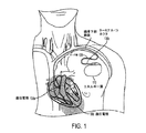
図1は、ペースメーカーの植え込みの1例を示す略図である。リード線120は、一方の端部にターミナル・コネクタ130cを、他方の端部に遠位電極130aおよび130bを有する。リード線は、右または左鎖骨下静脈内に挿入され、遠位電極130aが心房壁に接触し、および/または遠位電極130bが心室に接触するように操作される。リード線の近位端(ターミナル・コネクタ)は、所望の律動またはパターンでリード線120を介して電気エネルギーを心臓に供給するエネルギー源に接続されるが、これはそれ自体皮下または筋肉下植え込み手技を施される。図1は、ペーシング・システムを正確に示すことを意図したものではなく、単に、デバイス植え込みの考え方を説明するために使用されているだけであることは理解されるであろう。例えば、2つの遠位電極が同じリード線にまとめられているものとして例示されているが、複数の電極がそれぞれエネルギー源に接続された独立した専用のリード線をそこに有することができる。典型的なペーシング・システムは、1つ、2つ、3つ、4つ、またはそれ以上のリード線および付随する電極を備えることができる。さらに、図1に示されている二重電極システムでは、一方の電極を遠位電極と称し、他方の電極を近位電極と称することができる(例えば、チップ電極およびリング電極は双極刺激に使用される)。
FIG. 1 is a schematic diagram illustrating an example of pacemaker implantation.
いろいろな理由からインプラントの後にリード線120を身体から抜去する必要がある場合がある。ペーシング・システムによって引き起こされる感染(例えば、植え込まれたリード線またはペーシング・ジェネレータ・ポケットから結果として生じる感染)は、医師が患者の安全のためリード線(複数可)を身体から抜去すべきと判定する主要な理由である。それに加えて、リード線への物理的損傷も、リード線を抜去することが必要になる理由である。例えば、リード線の破砕またはリード線を囲む絶縁材の損傷は、デバイスが最適な動作をしない、全く機能しない、および/または患者を危険にさらす原因ともなりえるため、リード線を抜去し、適宜交換する必要がある場合がある。以前に取り出したデバイスのリード線が身体内に残っていると、新しいリード線および/またはペーシング・デバイスに干渉するため取り除く必要がある場合がある。例えば、破棄されたリード線が静脈内の空間を占有し、新しいリード線を挿入するのを妨げる可能性があるため、破棄されたリード線は取り出す必要がある。
It may be necessary to remove the
リード線と身体との相互作用も、リード線を抜去する必要がある理由と言える。例えば、リード線の先端に過度の瘢痕組織があると、リード線が機能しなくなる可能性があり、および/またはこれにより、デバイスがエネルギー送達に関するデバイスの設計以上のエネルギーを供給することが必要になる場合がある。血流の中断、循環系または他の植え込まれたデバイスへのリード線の干渉、および/またはインプラントの部位における疼痛を引き起こすリード線による静脈閉塞に関して、すべて、リード線を抜去することが望ましい。患者の快適さ、安全性、および/または生活のためにリード線抜去が必要であると医師が判定する原因となる他の多くの合併症が発生しうる。例えば、医師は、潜在的に危険なリコールされたデバイスからのリード線を交換するか、または新しい技術的進歩を活用するために旧いデバイスを新しいデバイスに更新することの望んでいる場合がある。 The interaction between the lead wire and the body is also the reason why the lead wire needs to be removed. For example, excessive scar tissue at the tip of the lead can cause the lead to fail and / or require the device to supply more energy than the device design for energy delivery. There is a case. With regard to vascular occlusion with leads that cause blood flow interruptions, lead interference with the circulatory system or other implanted devices, and / or pain at the site of the implant, it is desirable to remove the leads. Many other complications can occur that cause the physician to determine that lead removal is necessary for patient comfort, safety, and / or life. For example, a physician may want to replace a lead from a potentially dangerous recalled device or update an old device to a new device to take advantage of new technological advances.
多くの従来のリード線抜去デバイスは、拡張可能(「ロッキング」)ワイヤをリード線の内腔内に螺通することによって動作する。標準的なペースメーカー・リード線は、リード線の軸にそって中空の中心部(内腔)を有するコイル巻きワイヤから形成される。リード線内腔を使用して、身体からリード線を抜去するのを補助することができる。このようなリード線抜去デバイスは、典型的には、遠位端(例えば、リード線が心室または心房壁内に固定される場所)に到達するまで内腔内に螺通されたリード線の内径より小さい外径を持つガイド・ワイヤを備えることによって動作する。 Many conventional lead extraction devices operate by threading an expandable ("locking") wire into the lead lumen. A standard pacemaker lead is formed from a coiled wire having a hollow center (lumen) along the lead axis. The lead lumen can be used to assist in removing the lead from the body. Such lead extraction devices typically have an inner diameter of a lead that is threaded into the lumen until it reaches the distal end (eg, where the lead is secured within the ventricle or atrial wall). It works by providing a guide wire with a smaller outer diameter.
ガイド・ワイヤは、リード線の内部ワイヤ・コイルと係合し、同内部ワイヤ・コイルを把持するように拡張できる遠位部分を備えることができる。例えば、ガイド・ワイヤの遠位端は、ガイド・ワイヤがリード線の遠位端(例えば、植え込み端)に到達した後、ガイド・ワイヤの近位側から巻を解くことができるワイヤのコイルを備えることができる。ワイヤの巻が解けるにつれ、これはリード線の内部ワイヤ・コイルと絡まり、ガイド・ワイヤの遠位端を固定する。次いで、ガイド・ワイヤを引き出し、それにそってリード線を抜去することができる。 The guide wire can include a distal portion that can be extended to engage and grasp the inner wire coil of the lead. For example, the distal end of the guide wire may be a coil of wire that can be unwound from the proximal side of the guide wire after the guide wire reaches the distal end of the lead (eg, the implanted end). Can be provided. As the wire is unwound, it entangles with the internal wire coil of the lead and secures the distal end of the guide wire. The guide wire can then be withdrawn and the lead wire can be removed accordingly.
しかし、リード線抜去は、リード線の外面に付着している組織によって面倒なことになる可能性がある。例えば、リード線が植え込まれた後、瘢痕組織がいくつもの異なる部位(例えば、静脈内へのまたは静脈および/または心臓壁にそう任意の場所におけるリード線の挿入点)においてリード線の周りに形成する可能性があり、このため、外科医が周辺組織を引き裂くことなくリード線を抜去することが困難である。さらに、複数のリード線が静脈内に存在している場合、リード線は互いにくっつき合う可能性があり、従来のリード線抜去デバイスを使用したのでは問題となることの多い比較的複雑な手技に至ることになる。抜去にリード線の内腔を利用するリード線抜去デバイスは、リード線の外部に付着した線維組織の問題を解消せず、したがって、効果が得られない場合があるか、または過度の力を使用してリード線を抜去する場合に非常に重要な体内血管を引き裂き、患者に危険な、ときには致命的な障害を引き起こす著しい危険と隣り合わせで使用される。 However, lead wire removal can be cumbersome depending on the tissue attached to the outer surface of the lead wire. For example, after the lead is implanted, the scar tissue is around the lead at several different sites (eg, the point of insertion of the lead into the vein or anywhere in the vein and / or heart wall) This can make it difficult for the surgeon to remove the lead without tearing the surrounding tissue. In addition, if multiple leads are present in the vein, the leads may stick together, which is a relatively complex procedure that is often problematic when using conventional lead extraction devices. Will come. Lead extraction devices that utilize lead lumens for extraction do not eliminate the problem of fibrous tissue attached to the exterior of the lead and therefore may not be effective or use excessive force It is used next to a significant risk of tearing vital blood vessels when removing the lead and causing dangerous and sometimes fatal damage to the patient.
リード線の外周に付着する組織に関係する組織に対処するために、従来の方法およびデバイスでは、外科医が運用するナイフまたは刃付き器具で周辺組織を切断する、および/または周辺組織を切断して抜去するリード線を解放するレーザーもしくは電気エネルギーを供給するレーザーもしくは透熱デバイスを利用するさまざまな比較的初歩的な手動デバイスを使用してきた。例えば、遠位端に切断部分を有する中空シースをリード線上に螺合することができる。次いで、外科医は、手作業で、シースを強制的に前進させて、切断部分が付着組織と係合し、リード線からその組織を切り去るようにすることができる。外科医は、手作業でシースを回転させて切断しやすくし、および/またはシースに取り付けられ、トリガーが係合するとシースを回転させるトリガー・ガンを使用することもできる。いくつかの実施形態では、レーザーまたは透熱デバイスをリード線の切断部分に貼り付け、これにより、組織を切除してリード線から周辺組織を分離するのを補助する。 In order to deal with tissue related to tissue that adheres to the periphery of the lead, conventional methods and devices cut and / or cut the surrounding tissue with a knife or bladed instrument operated by the surgeon. A variety of relatively rudimentary manual devices have been used that utilize a laser to release the lead to be removed or a laser to provide electrical energy or a heat permeable device. For example, a hollow sheath having a cutting portion at the distal end can be screwed onto the lead. The surgeon can then manually advance the sheath so that the cutting portion engages the attached tissue and cuts the tissue off the lead. The surgeon may manually rotate the sheath to facilitate cutting and / or use a trigger gun that is attached to the sheath and rotates the sheath when the trigger is engaged. In some embodiments, a laser or heat permeable device is applied to the cut portion of the lead, thereby assisting in excising the tissue and separating the surrounding tissue from the lead.
本発明のいくつかの態様は、リード線抜去方法の少なくとも一部を半自動化または完全自動化するために圧力変化を使用することにより単純な、より安全な、より効果的なリード線抜去手法が得られるという出願人の評価から導かれるものである。例えば、1つまたは複数の液圧および/または気体圧技術を使用して、リード線にそってリード線抜去デバイスを固定し、および/または前進させ、および/またはリード線から組織を分離するか、または2本のリード線を互いに分離することを容易に行えるようにすることができる。「固定」または「固定する」という言い回しは、本明細書では、少なくとも1つの方向に少なくとも1つの部品、部分、またはコンポーネントの運動に抵抗する傾向を有する力/圧力を印加する機能を記述するために使用される。 Some aspects of the present invention provide a simpler, safer and more effective lead extraction technique by using pressure changes to semi-automate or fully automate at least part of the lead extraction method. It is derived from the applicant's evaluation that For example, one or more hydraulic and / or gas pressure techniques may be used to secure and / or advance and / or separate tissue from the lead wire along the lead wire Alternatively, the two lead wires can be easily separated from each other. The phrase “fixed” or “fixed” is used herein to describe the ability to apply a force / pressure that tends to resist movement of at least one part, part, or component in at least one direction. Used for.
いくつかの実施形態は、植え込まれたリード線を取り外すのを補助するための、リード線を収容するように適合された中心部を有する本体部分からなるデバイスと、リード線から組織を分離するのを補助するためにその本体部分に結合された切断コンポーネントと、少なくとも部分的にその本体部分内に配設されている、少なくとも一部は流体圧力を印加することによってリード線にそって本体部分の少なくとも一部の移動に抵抗する圧力をリード線に加えることができる、少なくとも1つの固定コンポーネントとからなる。 Some embodiments separate the tissue from the lead and a device comprising a body portion having a central portion adapted to receive the lead to assist in removing the implanted lead. A cutting component coupled to the body portion to assist in the body portion, and at least partially disposed within the body portion, at least a portion of the body portion along the lead by applying fluid pressure And at least one stationary component capable of applying pressure to the lead wire that resists movement of at least a portion of the lead wire.
いくつかの実施形態は、植え込まれたリード線を取り出すのを補助するためのデバイスを具備し、このデバイスはデバイスの中心部分を介してリード線を収容するための手段と、リード線から組織を分離するための手段と、リード線を圧迫し少なくとも一部は流体圧力を印加することによってリード線にそってデバイスの少なくとも一部の移動に抵抗するための手段とからなる。 Some embodiments comprise a device for assisting in removing an implanted lead, the device comprising means for receiving the lead through the central portion of the device and tissue from the lead. And means for resisting movement of at least a portion of the device along the lead by squeezing the lead and applying at least a portion of the fluid pressure.
いくつかの実施形態は、植え込まれたリード線を取り出すのを補助するように適合されたデバイスを操作する、少なくとも一部は流体圧力を印加することによってデバイスの第1の部分を固定することと、少なくとも一部は流体圧力を印加することによってリード線にそってデバイスの第2の部分を前進させることと、デバイスの第1の部分を解放することと、リード線にそってデバイスの第1の部分を前進させることとからなる方法を含む。 Some embodiments operate a device adapted to assist in removing an implanted lead, securing at least a portion of the first portion of the device by applying fluid pressure Advancing the second portion of the device along the lead by applying fluid pressure at least in part; releasing the first portion of the device; and A method comprising advancing a portion of one.
上で説明されているように、大半の従来のリード線抜去技術は、初歩的な手動切断デバイスまたはレーザーもしくは電気エネルギーを使用して周辺組織を切除するレーザーもしくは透熱デバイスのいずれかに依存する。従来の手動切断デバイスの短所として、手動デバイスは多くの場合に不格好で操作しにくい点が挙げられ、医師の器用さに対する信頼性に比較的重い負担がのしかかり、手術が複雑になる危険性が増大する。特に、切刃を操作し、デバイスを前進させて、リード線を完全に解放することは、相当に難しく、多くの場合、過度の組織損傷、さらなる合併症が生じ、および/またはリード線を抜去するために手術の侵襲性がますます高くなる。レーザーもしくは透熱デバイスは、従来の手動抜去デバイスと比較して、リード線抜去の複雑さおよび成功率に関するいくつかの改善点をもたらしうるが、機器は比較的高価であり、そのような手術を実施する外科医には利用可能でない場合がある。 As explained above, most conventional lead extraction techniques rely on either a rudimentary manual cutting device or a laser or heat permeable device that uses laser or electrical energy to ablate surrounding tissue. . Disadvantages of traditional manual cutting devices are that they are often clunky and difficult to operate, placing a relatively heavy burden on the reliability of the physician's dexterity and increasing the risk of complicated surgery To do. In particular, it is quite difficult to manipulate the cutting blade and advance the device to completely release the lead, often resulting in excessive tissue damage, further complications, and / or removal of the lead Therefore, the invasiveness of surgery becomes higher and higher. While laser or heat permeable devices can provide some improvements in lead extraction complexity and success rates compared to conventional manual extraction devices, the equipment is relatively expensive and makes such surgery It may not be available to the performing surgeon.
出願人は、リード線抜去方法の少なくとも一部を半自動化または完全自動化するために圧力変化を使用することにより単純な、より安全な、より効果的なリード線抜去手法が得られることを評価した。例えば、液圧および/または気体圧技術を使用することで、リード線にそってリード線抜去デバイスを前進させることができる。いくつかの実施形態によれば、1つまたは複数のバルーン、チューブ、または他のコンポーネントを膨らませ/萎ませ、デバイスをリード線上に固定し/または前進させ、および/またはリード線から組織を切断/分離するために、流体圧力の変化が利用される。本明細書で使用されているように、「膨らませる」という言い回しは、流体圧力を高くする操作を記述するものであり、「萎ませる」という言い回しは、流体圧力を低くする操作を記述するものである。「流体」という用語は、本明細書では、気体、液体、およびある種の固体(例えば、圧力変化を引き起こすために使用することができる発泡体または他の固形物)を記述するために使用される。いくつかの実施形態によれば、固定する、前進させる、および切断するという操作は、流体圧力技術を使用して行われる。 Applicants appreciated that using pressure changes to semi-automate or fully automate at least part of the lead extraction method provides a simpler, safer and more effective lead extraction technique. . For example, using a hydraulic and / or gas pressure technique, the lead extraction device can be advanced along the lead. According to some embodiments, one or more balloons, tubes, or other components are inflated / deflated, the device is secured / or advanced over the lead and / or the tissue is cut / A change in fluid pressure is utilized to separate. As used herein, the phrase “inflate” describes an operation that increases fluid pressure, and the phrase “deflates” describes an operation that decreases fluid pressure. It is. The term “fluid” is used herein to describe gases, liquids, and certain solids (eg, foams or other solids that can be used to cause pressure changes). The According to some embodiments, the operations of securing, advancing, and cutting are performed using fluid pressure techniques.
以下では、本発明による方法および装置に関係するさまざまな概念および実施形態のより詳細な説明を行う。本明細書で説明されている本発明のさまざまな態様は、多くの方法のうちのどれかで実装されうることは理解されるであろう。特定の実装例は、本明細書では例示することのみを目的として提示されている。それに加えて、以下の実施形態において説明されている本発明のさまざまな態様は、単独で使用することができるか、または任意の組み合わせで使用することができ、本明細書で明示的に説明されている組み合わせに限定されない。 The following provides a more detailed description of various concepts and embodiments relating to the method and apparatus according to the present invention. It will be appreciated that the various aspects of the invention described herein may be implemented in any of a number of ways. Particular implementations are presented herein for purposes of illustration only. In addition, the various aspects of the invention described in the following embodiments can be used alone or in any combination and are explicitly described herein. The combination is not limited.
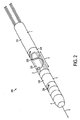
図2は、本発明のいくつかの実施形態によるリード線抜去デバイスを例示している。デバイス200は、心臓リード線を収容するための少なくとも十分な広さを持つ中空の中心軸を有する本体部5からなる。本体部は、近位部分1、拡張部分2、遠位部分3、および切断部分4を備える。切断部分4は、デバイスの遠位端(例えば、遠位部分3の一方の端部)に配置され、例えば、リード線を収容するように設計された開口部を有し、デバイスが矢印6で示される方向にリード線にそって前進するにつれリード線上で成長した組織を切断することができる円形の刃であるものとしてよい。
FIG. 2 illustrates a lead extraction device according to some embodiments of the present invention. The
いくつかの実施形態では、切断部分4は、デバイスがリード線にそって前進するにつれ回転し、これにより、リード線上で成長したか、または他の何らかの形でリード線に付着している組織からリード線を分離することがしやすくなり、および/または2つが2つのリード線を互いから隔てる。他の実施形態では、この刃は回転せず、組織分離は以下でさらに詳しく説明するように切断部分がリード線にそって前進することによって実行される。切断部分は、回転と前進を同時に行うか、または回転と前進を2つの別々の、独立した運動とすることができる。切断部分の回転は、単一方向の回転(例えば、時計回りの回転)であるか、または回転を時計回りと反時計回りの交互の回転とすることもできる。切断部分は、完全に回転するか、または部分回転のみに影響するものとしてよく、本発明の態様は特定の切断機構との併用に限定されない。 In some embodiments, the cutting portion 4 rotates as the device advances along the lead, thereby causing tissue from growing on the lead or in some other way attached to the lead. It is easier to separate the leads and / or two separate the two leads from each other. In other embodiments, the blade does not rotate and tissue separation is performed by advancing the cut along the lead as will be described in more detail below. The cutting portion can rotate and advance simultaneously, or the rotation and advance can be two separate, independent movements. The rotation of the cutting portion can be a unidirectional rotation (eg, clockwise rotation), or the rotation can be alternating clockwise and counterclockwise rotation. The cutting portion may rotate completely or affect only partial rotation, and aspects of the invention are not limited to use with a particular cutting mechanism.
近位部分1は、切刃の反対側のデバイスの端部に配置することができ、膨らんだときにリード線を把持するように適合された1つまたは複数の固定バルーン210を収納することができる。いくつかの実施形態では、固定バルーンは、以下でさらに詳しく説明するように、萎んだときにリード線が妨げられずにドーナツ形状の中心を通り、膨らんだときにバルーンがリード線を制約し把持してデバイスを固定することができるようなドーナツ形状である。「バルーン」という用語は、本明細書では、流体圧力下で変化する1つまたは複数の部分を有する構造または構造の組み合わせを指す。例えば、バルーンは、強制流体(例えば、強制空気、液体、または発泡体などの固体)を使用して膨らませることおよび/または萎ませることができる1つまたは複数の部分を有する構造物(複数可)を備えることができる。バルーンは、バルーンを膨らませ/萎ませた後にどのような効果が望ましいかによって単一のコンポーネントであるか、または複数のコンポーネントから形成することができる(例えば、伸長、締め付け、固定など)。
The
図3Aおよび3Bは、本発明のいくつかの実施形態による、それぞれ萎んだ状態と膨らんだ状態の両方の固定コンポーネント(例えば、固定バルーン)の断面図を例示している。図3Aおよび3Bを見ると、固定コンポーネントは比較的剛性の高い材料(例えば、鋼鉄製チューブ、シリコーン製チューブ、またはポリマー・チューブ)から形成された外側チューブ305と比較的弾性のある材料(例えば、シリコーン、ナイロン、ポリマー、または医療用バルーンおよび/または配管が形成される他の材料)から形成された内側チューブを備える。
FIGS. 3A and 3B illustrate cross-sectional views of an anchoring component (eg, anchoring balloon) in both a deflated state and an inflated state, respectively, according to some embodiments of the present invention. Referring to FIGS. 3A and 3B, the stationary component may include an
図3Aに例示されている萎んだ状態では、外側チューブと内側チューブとの間にギャップ307aが存在し、これにより、内側チューブ315とリード線375との間にギャップ307bがあり、固定コンポーネントがリード線の長さ方法にそって移動できるように内側チューブ315とリード線375との間の十分な空間または抵抗の欠如があるようにギャップ内の圧力で内側チューブを弛緩させることができる。固定コンポーネントを膨らませることは、流体(例えば、空気、液体など)をギャップ307aに強制的に送り込み、増大した圧力を内側チューブに加えるようにすることができる。外側チューブは比較的剛性があり、拡張に対する抵抗性があるため、図3Bに例示されているように、圧力を高めることで、内側チューブを内に向かって凹ませ、リード線を把持し、リード線に関して固定コンポーネントを固定する。特に、ギャップ307は、流体が膨らむことで内側チューブがリード線の方へ圧迫されること、および内側チューブがリード線の周りを締め付けるにつれてギャップ307bが減少し、および/または完全に取り除かれることによって引き起こされる増大した圧力の下で拡張する。
In the deflated state illustrated in FIG. 3A, there is a gap 307a between the outer tube and the inner tube, so that there is a gap 307b between the
図3Cおよび3Dは、代替的実施形態による、萎んだ状態と膨らんだ状態の両方の状態の固定バルーンの断面を例示している。バルーン310は、バルーンが萎んだときに、心臓リード線を収容することができる口径を有する中心孔を形成するドーナツ形のバルーンとすることができ、これにより、リード線とバルーンとの間の相対移動が可能になる。図3Cに例示されているように、バルーン310が萎み、リード線375は、バルーンの内壁がリード線を把持しなくなるとともに比較的妨げられることなくバルーンの中心を通過し、これにより、バルーンはリード線の上下に摺動することができる。図3Dでは、バルーン310は、バルーンの内壁がリード線を把持し、これらの間の摩擦がリード線に相対的なバルーンの運動を妨げるように膨らんでいる。つまり、膨らむことで流体がバルーンを満たし、それと同時に内壁がリード線を把持するまで中心孔のサイズを縮小する。固定バルーンは、バルーンの中心を通してリード線を収容するように設計される必要はない。例えば、リード線の上、リード線の下、またはリード線の横にバルーンを配設し、バルーンが膨らんだときに、バルーンが圧力をリード線に印加し、バルーンがリード線とリード線抜去デバイスの何らかの部分との間の相対移動に抵抗するようにすることができる。
3C and 3D illustrate a cross section of a fixed balloon in both a deflated state and a bulged state, according to an alternative embodiment. The
外向きの方向にバルーン310が拡張することは、例えば、バルーンの外向きの拡張が妨げられ、膨らんだ結果がもっぱら、または実質的に中心孔の内向きの締め付けとなるように比較的剛性の高いチューブ(例えば、リード線抜去デバイスの本体部または外側チューブ)の内側にバルーンを設けることによって、実質的に妨げることができることは理解されるであろう。比較的剛性の高いチューブは、金属、プラスチック、ポリマー、シリコーン、または他の好適な材料などの任意の材料から形成されうる。バルーンの外向きの拡張は、本発明の態様がこの点に限定されていないので、他の方法で妨げることができる。
Expansion of the
図3Cおよび3Dに例示されているバルーンは、ドーナツ形であるが、固定バルーンは、リード線の把持および解放を行うことができる形状であればどのような形状のものでもよいことは理解されるであろう。圧力変化を使用して固定を行う他の方法も、本発明の態様がこの点に限定されていないので使用することができる。図3A〜3Dの固定バルーンの断面は、バルーンの膨張を介した固定の原理を説明するために単に概略を示しているだけであることは理解されるであろう。例示されている寸法は、実際の絶対または相対寸法を示すように意図されていない。 The balloon illustrated in FIGS. 3C and 3D is doughnut-shaped, but it is understood that the fixation balloon may be of any shape that can grip and release the lead. Will. Other methods of securing using pressure changes can also be used because aspects of the invention are not limited in this respect. It will be appreciated that the cross section of the fixation balloon of FIGS. 3A-3D is merely schematic to illustrate the principle of fixation via balloon inflation. The dimensions illustrated are not intended to indicate actual absolute or relative dimensions.
再び図2を参照すると、拡張部分2はバネ機構225と伸長コンポーネント220(例えば、1つまたは複数の伸長バルーン)を備えている。バネ機構225は、近位部分を遠位部分に連結し、伸長バルーン220は、膨らんだときにバネを引き伸ばし、萎んだときにバネを静止位置に戻すことができるように構成される。伸長コンポーネントは、内側チューブおよび外側チューブから形成することができ、これらは両方とも比較的フレキシブルであるものとしてよい。内側チューブおよび外側チューブは、それぞれの端部(例えば、拡張部分が近位部分に連結する端部および拡張部分が遠位部分に連結する端部)で互いに連結されうる。
Referring again to FIG. 2, the
内側チューブと外側チューブとの間の空間を膨らませることで、伸長コンポーネント220は拡大し、これにより、バネが引き伸ばされ、近位部分と遠位部分との間の距離が増大する。空間が萎むと、バネが弛緩して静止位置に戻り、これにより、デバイスの遠位部分と近位部分との間の距離が減少する。バネ機構225は、標準的なバネまたは流体圧力下で伸長できるアコーディオン型の材料などの任意の種類のコンポーネントであってよい。
By inflating the space between the inner and outer tubes, the
遠位部分3は、デバイスの遠位端でリード線を把持するように配置された1つまたは複数の遠位固定バルーン(または任意の種類の固定機構)を備えることができる。本発明の態様はこの点に限定されないので、1つまたは複数の遠位固定バルーンは、図3A〜3Dに関連して説明されている固定バルーンと似た構造および動作を有するか、または流体圧力下でリード線の把持および解放を好きなように行うことができる他の任意の種類のコンポーネントであってもよい。デバイス200は、デバイスがリード線にそって前進するにつれ切断部分を回転させるように切断部分に結合されている回転コンポーネント234も備えることができる。図2において、以下でさらに詳しく説明されるように、回転コンポーネント234は、回転を行わせるための部材をデバイスの近位端と遠位端の両方に有し、スロットおよびピンの機構を使用することができる。本発明の態様は特定の種類の回転コンポーネントと併用することに限定されないため、他の種類の回転機構も使用できる(そのいくつかの実施形態も以下で説明する)。
The distal portion 3 can comprise one or more distal fixation balloons (or any type of fixation mechanism) arranged to grasp the lead at the distal end of the device. Since aspects of the present invention are not limited in this regard, the one or more distal fixation balloons have a structure and operation similar to the fixation balloon described in connection with FIGS. It can be any other type of component that can be gripped and released underneath as desired.
図4A〜4Fは、いくつかの実施形態により、リード線上でデバイスを前進させ、リード線の取り外しを妨げうる付着した組織からリード線を分離する抜去動作サイクルのいくつかの段階のうちのそれぞれの段階におけるリード線抜去デバイスの内部コンポーネント(例えば、図2に例示されているリード線抜去デバイス200の内部コンポーネント)を例示している。デバイス200と同様に、デバイス400も、近位固定バルーン410、拡張バルーン420、遠位固定バルーン430、およびデバイスの遠位部分と近位部分とを連結するバネ425を備える。デバイス400は、例えば、リード線の露出している端部をシースの中心軸に螺通する外科医によって、リード線495上に挿入されるように示されている。
FIGS. 4A-4F illustrate each of several stages of an extraction cycle that advances a device over a lead and separates the lead from attached tissue that can prevent removal of the lead, according to some embodiments. 3 illustrates internal components of a lead extraction device in a stage (eg, internal components of
図4Aは、デバイスがリード線上に配置された後、リード線抜去デバイスの動作サイクルの第1の段階を例示している。第1の段階では、バルーンのすべてを萎ませておくことができる。特に、固定バルーン410および430は、デバイスがリード線にそって摺動できるように萎む(つまり、リード線はいずれかの固定バルーンによって比較的妨げられずにシースの中心を通過することができる)。この段階で、外科医は、シースの中心にリード線を螺通し、リード線を抜去するようにデバイスを位置決めすることができる。それに加えて、拡張バルーン420は、バネ425が静止し、遠位および近位部分がバネが許容する限り近づくように萎ませることもできる。この段階から、デバイスはリード線の抜去を開始する用意ができている。
FIG. 4A illustrates the first phase of the operational cycle of the lead extraction device after the device is placed on the lead. In the first stage, all of the balloons can be deflated. In particular, fixation balloons 410 and 430 are deflated so that the device can slide along the lead (ie, the lead can pass through the center of the sheath relatively unimpeded by either fixation balloon. ). At this stage, the surgeon can thread the lead through the center of the sheath and position the device to remove the lead. In addition, the dilatation balloon 420 can be deflated so that the
図4Bは、リード線抜去デバイスの動作サイクルの第2の段階を例示している。第2の段階では、近位固定バルーン410は、バルーンがリード線を把持するように膨らみ、リード線に相対的な近位部分の運動が妨げられるようにデバイスの近位部分を固定する。例えば、近位固定バルーン410は、内側チューブが内向きに圧迫されてリード線を把持するように萎んだ状態(例えば、図3Aに示されているような)から膨らんだ状態(例えば、図3Bに示されているような)に遷移することができる。あるいは、近位固定バルーン410は、図3Cおよび3Dに関連して説明されているドーナツ形のバルーンとして実装することができ、膨張により、中心孔が通されたリード線の周りを締め付ける。
FIG. 4B illustrates the second stage of the operating cycle of the lead extraction device. In the second stage, the
図4Cは、リード線に付着している可能性のある組織を分離する、リード線にそってデバイスの遠位部分を前進させる動作サイクルの第3の段階を例示している。この第3の段階では、伸長バルーン420が膨らんでバネ425を引き伸ばす。デバイスの近位部分は、膨らんだ固定バルーン410によって固定されるので、バネが伸長バルーン420によって引き伸ばされるにつれバネがリード線にそって遠位部分を強制的に前進させる。遠位部分にかかる前進させる力により、切断部分がリード線にそって前進し、リード線に付着している組織を切断してリード線を抜去する準備をする。いくつかの実施形態では、前進させる力は、切断部分も回転させ、以下でさらに詳しく説明するように、リード線から組織を分離することがしやすくなる。
FIG. 4C illustrates the third stage of the operational cycle of advancing the distal portion of the device along the lead that separates tissue that may be attached to the lead. In this third stage, the expansion balloon 420 is inflated to stretch the
図4Dは、デバイスの遠位部分をリード線に固定する動作サイクルの第4の段階を例示している。遠位部分がリード線にそって前進した後、遠位固定バルーン430は、リード線を把持するように膨らませることができる。固定バルーン430は、上述の近位バルーン410と同じまたは類似の方法で動作しうる。この段階で、デバイスの近位端および遠位端は両方とも、リード線に固定されており、バネ425は、膨らんだ伸長バルーン420によって引き伸ばされる。固定バルーン430は、膨張チューブまたは他の膨張機構を備えることができるけれども、そのような機構は図4A〜4Fに例示されていないことは理解されるであろう。あるいは、固定バルーン430は、遠位固定コンポーネントを膨らませること/萎ませることが必要とされないように実質的に一定の抵抗をリード線に相対的な移動に加える固定コンポーネントで置き換えることができるが、これらのうちいくつかの実施形態について以下でさらに詳しく説明する。
FIG. 4D illustrates the fourth stage of the operational cycle of securing the distal portion of the device to the lead. After the distal portion has been advanced along the lead, the
図4Eは、伸長バルーン420が萎んでバネ425を弛緩させ静止位置に戻す動作サイクルの第5の段階を例示している。伸長バルーン420を萎ませた後、または萎ませるのと同時に、近位固定バルーン410も萎む。遠位固定バルーン430は膨らむので、静止位置に戻るときの締め付けるバネの力によりデバイスの近位部分(近位固定バルーン410が萎んだことにより現在解放されている)が前方に引かれて、デバイスの近位部分をリード線にそって前進させる。次いで、遠位固定バルーンが萎んで、デバイスを第1の段階に戻すことができる。つまり、すべてのバルーンが萎むことができ、デバイスはその初期構成に戻るが、リード線にそって前進しており、動作サイクルが漸次進行している間に切断部分が遭遇した可能性のある組織を分離する(か、または部分的に切断/分離する)(例えば、図4Fを参照)。
FIG. 4E illustrates the fifth phase of the operating cycle when the expansion balloon 420 is deflated to relax the
これらの段階を繰り返し、デバイスが、本体部から引くことができるようにリード線を解放するために前進させる必要がある限り前進するまでデバイスを前進させ続けることができる。これは本発明の態様が特定のスケジュールで使用することに限定されていないので、さまざまな段階を逐次的に実行する必要はなく、段階の一部分または段階全体を同時に実行することもでき、および/または時間的に重なり合ってもよいことは理解されるであろう。 These steps can be repeated and the device can continue to advance until it has advanced as long as it needs to be advanced to release the lead so that it can be pulled from the body. This is not necessary for the aspects of the invention to be used on a particular schedule, so the various stages need not be performed sequentially, and some or all of the stages can be performed simultaneously, and / or It will be understood that they may overlap in time.
上述のリード線抜去デバイスは、リード線に付着している組織を分離し、および/またはそのリード線を付着している他のリード線から分離しながら、リード線にそってリード線バッグデバイスを前進させることをしやすくする多くの一般的な概念を具現化したものである。例えば、上述のリード線抜去デバイスは、印加された圧力の変化を使用して固定し、前進させ、および/または切断することを含めて、印加された圧力の変化を使用してリード線抜去デバイスを内部的に前進させる方法例を示している。固定すること、前進させること、および切断することは、いくつかの実施形態について以下でさらに詳しく説明されているさまざまな異なる方法で実行することができることは理解されるであろう。固定すること、前進させること、および切断することの概念を具現化する実装は、本発明の態様が明細書に特に例示されている特定の組み合わせに限定されないので、単独で使用するか、また任意の組み合わせで使用することができることもさらに理解されるであろう。 The lead extraction device described above separates the tissue attached to the lead and / or separates the lead bag device along the lead while isolating the lead from other leads attached. It embodies many general concepts that make it easier to move forward. For example, the lead extraction device described above uses a change in applied pressure, including fixing, advancing, and / or cutting using a change in applied pressure. Shows an example of how to advance internally. It will be appreciated that securing, advancing, and cutting can be performed in a variety of different ways, described in more detail below for some embodiments. Implementations that embody the concepts of securing, advancing, and cutting can be used alone or arbitrarily as aspects of the invention are not limited to the specific combinations specifically illustrated in the specification. It will be further understood that a combination of these can be used.
いくつかの実施形態では、遠位固定コンポーネントは、膨らませることができる/萎ませることができる固定コンポーネント(例えば、図3A〜3Dに例示されている膨らませることができる/萎ませることができる固定バルーン)の代わりに、一定摩擦コンポーネントから形成される。例えば、以下でさらに詳しく説明されるように、遠位固定コンポーネントは、係合していないとき(例えば、萎んでいるとき)にリード線上の近位固定コンポーネントの抵抗より大きく、係合しているとき(例えば、膨らんでいるとき)にリード線上の近位固定コンポーネントの抵抗より小さい一定の摩擦をリード線に加えることができる。 In some embodiments, the distal fixation component can be inflated / deflated, and can be inflated / deflated (eg, the inflatable / deflatable fixation illustrated in FIGS. 3A-3D). Instead of a balloon) it is formed from a constant friction component. For example, as described in more detail below, the distal fixation component is engaged greater than the resistance of the proximal fixation component on the lead when not engaged (eg, when deflated) Sometimes (eg, when inflated), a certain amount of friction can be applied to the lead that is less than the resistance of the proximal anchoring component on the lead.
図5は、本発明のいくつかの実施形態による、一定摩擦部分を有する遠位固定コンポーネントを例示している。近位固定コンポーネントは、流体圧力の変化によりリード線の固定および解放を望み通りに行うことができる本明細書で説明されている固定コンポーネントのうちのどれかとすることができる。同様に、拡張コンポーネント520は、リード線抜去デバイスの近位部分と遠位部分との間の距離を長くするために上述の機構のうちのどれかを備えることができる(例えば、1つまたは複数の伸長バルーン)。遠位固定コンポーネント530は、実質的に一定の摩擦をリード線に与える一定摩擦コンポーネントとしてよい。
FIG. 5 illustrates a distal fixation component having a constant friction portion according to some embodiments of the present invention. The proximal fixation component can be any of the fixation components described herein that can secure and release the lead as desired by changes in fluid pressure. Similarly, the
遠位固定コンポーネント530は、一定の摩擦を与えるためにリード線に接触するように内向きに曲げられた部分を有する比較的剛性が高いチューブとすることができる。例えば、剛性のあるチューブは、リード線をつまむように内向きに圧迫されうる1つまたは複数の穿孔タブ532を有し、これによりリード線にそった運動に対する所望の抵抗を生じるようにできる。代替的実施形態では、一定摩擦コンポーネントは、所望の位置でリード線と接触するバネを捻ることと、リード線に実質的に一定の摩擦を加える圧力とによって形成されうる。 The distal fixation component 530 can be a relatively stiff tube having a portion bent inward to contact the lead to provide a constant friction. For example, a rigid tube can have one or more perforated tabs 532 that can be squeezed inward to pinch the lead, thereby creating the desired resistance to movement along the lead. In an alternative embodiment, the constant friction component may be formed by twisting a spring that contacts the lead at a desired location and pressure that applies a substantially constant friction to the lead.
上述のように、遠位固定コンポーネントは、近位固定コンポーネントが係合していないときに近位固定コンポーネントの抵抗より大きく、近位固定コンポーネントが係合しているときに近位固定コンポーネントの抵抗より小さい実質的に一定の抵抗を有するものとしてよい。こうして構成されると、近位固定コンポーネントがリード線と係合し、伸長コンポーネントが膨らまされてバネ機構を引き伸ばす場合、近位固定コンポーネントは遠位固定コンポーネントの摩擦が一定であるにもかかわらず、リード線に相対的な移動に対しより大きな抵抗をもたらすため、遠位部分は強制的に前進させられ、リード線にそって進む。伸長コンポーネントおよび近位固定コンポーネントが萎んだ場合、一定摩擦コンポーネントは、バネ機構が静止位置に戻るときに、近位部分(係脱されている)が遠位部分に向かって引かれ、リード線にそってデバイスを前進させるように移動に対するより大きな抵抗をもたらす。 As described above, the distal fixation component is greater than the resistance of the proximal fixation component when the proximal fixation component is not engaged and the resistance of the proximal fixation component when the proximal fixation component is engaged. It may have a smaller, substantially constant resistance. When configured in this way, when the proximal anchoring component engages the lead and the extension component is inflated to stretch the spring mechanism, the proximal anchoring component will be in spite of the constant friction of the distal anchoring component. In order to provide greater resistance to movement relative to the lead, the distal portion is forced forward and advanced along the lead. When the extension component and the proximal fixation component are deflated, the constant friction component causes the proximal portion (disengaged) to be pulled toward the distal portion when the spring mechanism returns to the rest position, leading to the lead There is therefore greater resistance to movement as the device is advanced.
リード線抜去デバイスのいくつかの実施形態の目的は、リード線上に成長した、またはリード線にそれ自体付着した組織を分離して、周辺組織をいたずらに引き裂き/または損傷することなくリード線取り出しを容易にすることである。上述のように、組織を切断しリード線から組織を分離する作業を補助するように設計された1つまたは複数の刃を持つ切断部分(例えば、ナイフまたは切刃)を備えることによって分離を実行することができる。いくつかの実施形態では、リード線抜去デバイスの前進運動は、リード線から組織を分離するための力をもたらす。しかし、他の実施形態では、リード線抜去デバイスの切断能力は、前進運動の他にさらに回転を加えることによって改善することができる。回転する切断部分の非限定的な多数の実施形態について以下でさらに詳しく説明する。 The purpose of some embodiments of the lead extraction device is to separate tissue that has grown on or attached to the lead so that the lead can be removed without unnecessarily tearing / damaging the surrounding tissue. To make it easier. As described above, performing separation by providing a cutting portion (eg, a knife or cutting blade) with one or more blades designed to assist in the work of cutting tissue and separating tissue from a lead. can do. In some embodiments, the forward movement of the lead extraction device provides a force to separate tissue from the lead. However, in other embodiments, the cutting ability of the lead extraction device can be improved by applying further rotation in addition to the forward motion. A number of non-limiting embodiments of rotating cutting portions are described in further detail below.
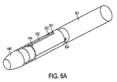
図6Aおよび6Bは、動作中に切断部分の回転を揺するスロットおよびピンの機構を例示している。図6Aは、いくつかの実施形態による、デバイスの遠位端の前進の間に切断部分を回転させる回転機構に結合された切断部分を有するリード線抜去デバイスを例示している。図6Aおよび6Bには、回転にかかわるコンポーネントが例示されているが、デバイスの他のコンポーネントは、説明には含まれているけれども、図面から省略されうる。デバイスの部分は、比較的剛性のあるチューブ601、切断部分640、および部材634、部材644、ピン631、軸方向スロット632、および斜めスロット633を備える回転コンポーネントを具備する。
6A and 6B illustrate a slot and pin mechanism that swings the rotation of the cutting portion during operation. FIG. 6A illustrates a lead extraction device having a cutting portion coupled to a rotating mechanism that rotates the cutting portion during advancement of the distal end of the device, according to some embodiments. Although components involved in rotation are illustrated in FIGS. 6A and 6B, other components of the device are included in the description but may be omitted from the drawings. The portion of the device comprises a rotating component comprising a relatively
部材634は、デバイスの遠位部分に結合され、デバイスが伸長したときに(例えば、1つまたは複数の伸長バルーンが膨らんだときに)強制的に前進させられ、ピン631は、部材634に取り付けられる。部材644は、切断部分に結合され、斜めスロット633を備える。部材634が前進すると、ピンは斜めスロットに当たって圧迫し、部材644を回転させるとともに前進させ、これにより、切断部分に回転と前進を同時に行わせて、リード線抜去デバイスの伸長フェーズの間に入った組織を切断する。ピンおよびスロットの機構は、本発明の態様がこの点に限定されていないので、他の方法で実装することができる。
図7Aおよび7Bは、本発明のいくつかの実施形態による、回転機構に結合された切断部分を有するリード線抜去デバイスを例示している。図7の回転機構の動作の背後にある前提条件は、往復動作コンポーネントの連動、例えば、係合できる連動する歯、プロング、または他の連携構造物の連動を伴う。図7には、デバイスを回転させることにかかわるコンポーネントが例示されているが、他のコンポーネントは省略できる。リード線抜去デバイスは、比較的剛性のあるチューブ708を備え、その一部は近位固定バルーンの外径をなすものとしてよい。
7A and 7B illustrate a lead extraction device having a cutting portion coupled to a rotating mechanism, according to some embodiments of the present invention. The prerequisites behind the operation of the rotating mechanism of FIG. 7 involve the interlocking of reciprocating components, for example interlocking interlocking teeth, prongs or other interlocking structures that can be engaged. FIG. 7 illustrates components involved in rotating the device, but other components can be omitted. The lead extraction device may comprise a relatively
回転コンポーネントは、2つの連携する回転部材770、780からなり、それぞれ互いに対応し、くっつけたときに係合する相互にかみ合う歯を有する。部材724は、デバイスの遠位部分とともに移動し、部材770の片側に付着する。したがって、部材724が強制的に前進させられると(例えば、伸長バルーンが膨らむことで)、部材770も前進して図7Bに例示されているように部材780と係合する。次いで、部材780は、切断部分740に結合される。部材770および780が係合した後、切断部分は、部材770が強制的に前進させられると回転し、数回転することでデバイスの伸長動作が実行される。伸長コンポーネントが収縮すると、部材770および780は係脱し、図7Aに例示されている位置に戻る。こうして、切断部分は、動作サイクルの伸長段階の間にのみ回転する。
The rotating component consists of two cooperating rotating
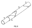
図8は、本発明のいくつかの実施形態による、回転コンポーネントに結合された切断部分を有するリード線抜去デバイスの正面部分を例示している。上述のように、切断部分を回転させるコンポーネントが例示されているが、他のコンポーネントは省略できる。図8のリード線抜去デバイスは、伸長(例えば、遠位部分の前進)および収縮(例えば、近位部分の前進)の両方の間に切断部分を回転させることができる回転コンポーネントとともに設計される。回転コンポーネントは、3つの回転部材870、880、および890を含む。回転部材870および880の原理および動作は、回転部材870が強制的に前進させられ回転するときに、これは回転部材880と係合したときに切断部分840を回転し、遠位部分の前進の間(例えば伸長フェーズの間)に切断部分の前進および回転を行わせるという点で、図7Aおよび7Bに関連して上で説明されている連携する回転部材770および780に類似している。
FIG. 8 illustrates a front portion of a lead extraction device having a cutting portion coupled to a rotating component, according to some embodiments of the present invention. As described above, the component for rotating the cutting portion is illustrated, but other components can be omitted. The lead extraction device of FIG. 8 is designed with a rotating component that can rotate the cutting portion during both extension (eg, distal portion advancement) and contraction (eg, proximal portion advancement). The rotating component includes three
それに加えて、回転部材880は、回転部材部材870および回転部材890の両方と係合する歯構造を備え、後者はデバイスの近位部分の前進の間(例えば、収縮フェーズの間)に切断部分の回転を行わせる。回転部材890は、切断部分の上に摺動し、回転部材870と同じ方向に強制的に移動させられうる。デバイスの拡張部分が長くなると、回転部材870、したがって回転部材890は、デバイスの遠位端の方へ強制的に動かされる。
In addition, the rotating
上述のように、回転部材870は回転部材880と係合して、拡張部分が伸びるにつれ切断部分を前進させ、回転させる。拡張部分が収縮した場合、回転部材870は近位端の方へ戻り、同じ方向に回転部材890を強制する。回転部材880は、他の回転部材から力が加えられていない場合に静的状態のままであるため、回転部材890は、これが近位端の方へ移動するにつれ回転部材880と係合し、回転させる。回転部材880が回転すると、切断部分は伸長段階と収縮段階の両方で回転する(例えば、遠位部分がリード線にそって前進するときと、遠位部分がリード線にそって前進するときの両方)。
As described above, the rotating
本発明のいくつかの態様では、流体圧力の変化を利用して固定、前進、および/または切断を行わせる基礎的概念を組み込んでいる。いくつかの実施形態によれば、流体圧力の変化により、バルーンは膨らむか、または萎む。リード線抜去デバイスによる固定、前進、および/または切断を行わせるためにバルーンを膨らませる/萎ませることができる方法は多数ある。図9は、本発明のいくつかの実施形態による、チューブを介してバルーンを膨らませる方法を例示している。図9では、チューブ905は、近位固定バルーン910に結合されており、これにより流体が近位固定バルーン内に強制的に送り込まれ、バルーンを膨らませリード線を把持することができる。同様に、チューブ915は、伸長バルーン920に結合されており、これにより、流体がバルーン内に強制的に送り込まれ、バルーンを伸長し、バネ機構を引き伸ばすことができる。
Some aspects of the present invention incorporate basic concepts that utilize changes in fluid pressure to cause locking, advancement, and / or cutting. According to some embodiments, a change in fluid pressure causes the balloon to inflate or deflate. There are many ways in which the balloon can be inflated / deflated for fixation, advancement, and / or cutting with a lead extraction device. FIG. 9 illustrates a method for inflating a balloon through a tube, according to some embodiments of the present invention. In FIG. 9, the
遠位固定バルーンを含む実施形態では、同じ方法で遠位固定バルーンを膨らませるように第3のチューブを実装することができる。チューブは、各バルーンに流体を供給することができる種類であればどのようなものでもよい(例えば、空気、液体、または発泡体などの固体)。例えば、チューブはアコーディオンの形状のものであり、および/または引き伸ばすことができるものであってよい。膨張チューブの断面は、円形であるものとして図示されているが、断面は、本発明の態様がこの点で限定されていないので、任意の形状(例えば、楕円)をとることができる。あるいは、以下でさらに詳しく説明されるように、膨らませる各コンポーネントのそれぞれの周りに同心円状に配置された環状チューブによって膨らませる操作を行うことができる。 In embodiments that include a distal fixation balloon, a third tube can be implemented to inflate the distal fixation balloon in the same manner. The tube can be of any type that can supply fluid to each balloon (eg, air, liquid, or solid such as foam). For example, the tube may be in the form of an accordion and / or be stretchable. Although the cross section of the inflation tube is illustrated as being circular, the cross section can take any shape (eg, an ellipse) because aspects of the invention are not limited in this respect. Alternatively, as will be described in more detail below, the inflating operation can be performed by an annular tube disposed concentrically around each of the inflatable components.
膨張チューブは、流体をポンプでデバイス内に(例えば、各バルーン内に)送り込むことを可能にする各ポンプ機構に結合されうる。例えば、ポンプ機構は、バネ付きの注射器であってもよく、注射器のハンドルまたはプランジャを圧して空気/流体を強制的にバルーン内に押し込む。いくつかの実施形態では、流体は液体(例えば、水、食塩水、または他の何らかの望ましい溶液)であり、したがって、水圧を利用してリード線抜去デバイスを操作する。いくつかの実施形態では、流体は気体(例えば、圧縮空気または非活性もしくは不活性ガスなどの他の何らかの気体)であり、したがって、気体圧を利用してリード線抜去デバイスを操作する。いくつかの実施形態では、液圧技術と気体圧技術の組み合わせも、本発明の態様がこの点に限定されていないのでリード線抜去デバイスの操作に使用することができる。 An inflation tube can be coupled to each pump mechanism that allows fluid to be pumped into the device (eg, into each balloon). For example, the pump mechanism may be a spring-loaded syringe that presses the syringe handle or plunger to force air / fluid into the balloon. In some embodiments, the fluid is a liquid (eg, water, saline, or some other desired solution), and therefore, water pressure is utilized to operate the lead extraction device. In some embodiments, the fluid is a gas (e.g., compressed air or some other gas such as an inert or inert gas), thus utilizing gas pressure to operate the lead extraction device. In some embodiments, a combination of hydraulic and gas pressure techniques can also be used to operate the lead extraction device as aspects of the invention are not limited in this respect.
いくつかの実施形態によれば、ポンプ機構は、手動で流体をバルーン内に圧送することができる圧送ポンプとしてよい(例えば、血圧計のバンドを膨らませるために一般に使用されるスクイーズボールと同様のもの)。圧送ポンプは、圧力を緩めて萎ませるための放出弁を備えることができる。各バルーンを膨らませるためにさまざまな好適なポンプ機構をモーターに接続することができる。例えば、ポンプ機構は、強制流体を生成することができる圧縮装置の一部とすることもできる。流体が1つまたは複数の膨張チューブを介してバルーンに送達される上述の実施形態の代替的形態として、バルーンの周りに同心円状に設けられた1つまたは複数の環状チューブを介して流体をデバイスに送達することができる。バルーンは、本発明の態様がバルーンを膨らませる/萎ませる特定の方法に限定されないので、他の任意の好適な手段によって膨らませる/萎ませることができることは理解されるであろう。 According to some embodiments, the pump mechanism may be a pumping pump that can manually pump fluid into the balloon (eg, similar to a squeeze ball commonly used to inflate a sphygmomanometer band). thing). The pump can include a release valve to relax and deflate the pressure. A variety of suitable pump mechanisms can be connected to the motor to inflate each balloon. For example, the pump mechanism can be part of a compression device that can generate a forced fluid. As an alternative to the above-described embodiment in which fluid is delivered to the balloon via one or more inflation tubes, the fluid is deviced via one or more annular tubes concentrically provided around the balloon Can be delivered to. It will be appreciated that the balloon can be inflated / deflated by any other suitable means, as embodiments of the present invention are not limited to a particular method of inflating / deflating the balloon.
図10は、本発明のいくつかの実施形態による、バネを使わずに動作が可能なリード線抜去デバイスの一部分を例示している。図10のリード線抜去デバイスの前進は、バルーンを膨らませるときと萎ませるときの両方において十分な力を発揮することができる機構によって駆動されうる。図9に関連して説明されているリード線抜去デバイスと同様に、バルーンは、チューブを介して膨らませる、および/または萎ませることができる。特に、近位固定バルーン1010は、膨張チューブ1005を介して膨らまされ、および/または萎まされ、伸長バルーン1020は、膨張チューブ1015を介して膨らまされ、および/または萎まされる。近位固定バルーンおよび伸長バルーンは、本明細書で説明されている機構と同様の方法で動作しうる。伸長バルーン1020は、遠位部分のパーツ1034を前方に押し、(回転機構1075を介して)ナイフを回転してデバイスの遠位部分を前進させる。
FIG. 10 illustrates a portion of a lead extraction device that can operate without using a spring, according to some embodiments of the present invention. The advancement of the lead extraction device of FIG. 10 can be driven by a mechanism that can exert sufficient force both when the balloon is inflated and when it is deflated. Similar to the lead extraction device described in connection with FIG. 9, the balloon can be inflated and / or deflated through the tube. In particular,
引き伸ばしたバネ機構の張力でデバイスの近位部分を遠位部分の方へ引く代わりに、実質的に同じ機能を実行する収縮バルーン1060を備えることができる。引き伸ばされたバネに蓄積されたエネルギーは、膨らんだ収縮バルーン1060に蓄積されるエネルギーで置き換えられる。つまり、伸長後、および伸長バルーン1020がまだ膨らんでいる最中に、収縮バルーン1060を膨らませて、遠位部分および近位部分が一緒になることに抵抗することができる(例えば、引き伸ばされたバネによってもたらされる抵抗と同様に)。伸長バルーンおよび遠位固定バルーンを萎ませることができる。その後収縮バルーンが萎むと抵抗が解放され、近位部分が遠位部分の方へ引かれ、デバイスの前進を完了する。この方法を繰り返すことで、リード線にそってデバイスを前進させることができる。本発明の態様はコンポーネントの特定の任意の組み合わせと併用することに限定されていないので、上述の切断部分および/または回転コンポーネントはどれも、図10に関連して上で説明されているバネを使わない実施形態に組み込むことができることは理解されるであろう。
Instead of pulling the proximal portion of the device toward the distal portion with the tension of the stretched spring mechanism, a deflated
上述のように、いくつかの従来のリード線抜去デバイスでは、医師/外科医がデバイスを手動で完全操作する必要がある。この方法は、デバイスを手動で強制的に前進させ連結している組織を切断しながら(例えば、遠位端にナイフを有するシースを強制的に前進させてリード線の取り出しに干渉する組織と係合させることによって)、リード線の一方の端部(例えば、本体部から突き出ている部分および/またはすでに抜去されている部分)を手動で固定することを含みうる。この方法は、外科医にとっては非常に扱いにくい場合があり、誤りを犯しがちである。より単純なリード線抜去を行いやすくするために、本明細書で説明されているさまざまな概念を単独で、または異なる組み合わせで使用し、完全手動のリード線抜去デバイスの改善を行うことができる。固定に関する概念を使用するリード線抜去デバイスのいくつかの例を、以下でさらに詳しく説明する。 As noted above, some conventional lead extraction devices require a physician / surgeon to fully manipulate the device manually. This method involves manually advancing the device to cut connected tissue (e.g., forcing tissue that has a knife at the distal end to interfere with removal of the lead wire). And by manually securing one end of the lead (eg, a portion protruding from the body portion and / or a portion that has already been removed). This method can be very cumbersome for surgeons and is prone to error. To facilitate a simpler lead extraction, the various concepts described herein can be used alone or in different combinations to improve a fully manual lead extraction device. Some examples of lead extraction devices that use the concept of fixation are described in more detail below.
図11Aは、本発明のいくつかの実施形態による、リード線抜去を補助するために内部固定を使用するリード線抜去デバイスの一部分を例示している。図11Bは、図11Aに例示されているリード線抜去デバイスの一部分の断面図である。いくつかの実施形態によれば、固定バルーン1130がリード線抜去デバイスの遠位端に備えられる。上述のように、リード線抜去に関するいくつかの従来の技術は、リード線上に遠位切断部分を有するシースを螺装し、塞いでいる組織に手動で強制的にシースを当て、および/またはシースを捻り、周辺組織の切除を容易にすることを伴う。そのようなデバイスの遠位端に追加された1つまたは複数の固定バルーンを使用すれば、周辺組織からリード線を分離することが容易になると思われる。
FIG. 11A illustrates a portion of a lead extraction device that uses internal fixation to assist in lead extraction, according to some embodiments of the present invention. FIG. 11B is a cross-sectional view of a portion of the lead extraction device illustrated in FIG. 11A. According to some embodiments, a
図11Aには、シース1011を有するデバイスの一部が例示されている。シース1101は、従来のシースであるか、またはリード線上に螺装することができる任意の種類のシースとすることができる。好ましくは、シースは、曲げに対しては比較的剛性が低いが、座屈および捻りに関しては比較的剛性が高い。しかし、本発明の態様は、特定の種類のシースまたは外側シェル/本体部と併用することに限定されていないので、適当なシースを使用することができる。シースは、遠位端に切断部分を備えるか、または切断部分なしの構成とすることもできる。1つまたは複数の固定バルーンをシースの遠位端に備えることができる。例えば、本明細書で説明されている種類の固定バルーン1130を、シースが望み通りにリード線に固定され、解放されうるように構成することができる。
FIG. 11A illustrates a portion of a device having a sheath 1011. The
デバイスを操作するために、外科医は、シースをリード線上に螺装し、付着している組織に到達するまでデバイスを押し込むことができる。外科医は、次いで、膨張チューブ1135を介して固定バルーン1130を膨らませてデバイスをリード線に固定することができる。デバイスが付着している組織の近くに固定された状態で、外科医は、デバイスを引っ張り、リード線を付着している組織から外すことができる。外科医は、周辺組織からリード線を解放するのを補助する捻り運動を行うこともできる。本発明の態様はこの点に限定されていないので、外科医は、デバイスを把持し、引っ張り、および/または手で捻るか、または他のデバイスを使用して、この運動を補助し、行いやすくすることができることは理解されるであろう。背景技術の項で説明されているように、このようなデバイスは、リード線の内腔を螺通し、内部リード線ワイヤ・コイルに固定する内部ワイヤデバイスとともに使用することもできることは理解されるであろう。例えば、固定されたワイヤガイドデバイスを、組織の方へ推し進めている間、および/または外科医が固定されたリード線抜去デバイスを引っ張り/捻るときのインターバルの間、引っ張ることができる。
To manipulate the device, the surgeon can screw the sheath onto the lead and push the device until it reaches the attached tissue. The surgeon can then inflate the
他の実施形態によれば、リード線を身体から抜去しやすくするために1つまたは複数の近位固定バルーンを使用することができる。例えば、図11Aおよび11Bに例示されているバルーンをリード線抜去デバイスの近位側に設け、外科医が連結されている遠位部分をリード線にそって強制的に前進させるときにデバイスを固定するのを補助することができる。例えば、リード線抜去デバイスは、内側シースおよび外側シースを有するデバイスなどの、近位部分とは独立して前進させることができる遠位部分を有することができ、外側シースはリード線から組織を分離するために外科医が手で前方へ押すことができる切断部分を有する。1つまたは複数の近位固定バルーンを備えることによって、外科医は、望み通りにデバイスを位置決めし、外科医が手でデバイスを固定することと遠位部分を前方へ強制的に押すことを同時に行わなくてもリード線抜去デバイスを固定することができる。その代わりに、外科医は、リード線に相対的に移動するデバイスの近位端を気にすることなく遠位端のところで組織を切断することに集中することができる。この結果、外科医の一方の手が空き、手術の困難さが軽減されうる。 According to other embodiments, one or more proximal fixation balloons can be used to facilitate removal of the lead from the body. For example, the balloon illustrated in FIGS. 11A and 11B may be provided proximal to the lead extraction device to secure the device when the surgeon is forced to advance the connected distal portion along the lead. Can help. For example, a lead extraction device can have a distal portion that can be advanced independently of the proximal portion, such as a device having an inner sheath and an outer sheath, the outer sheath separating tissue from the lead. To have a cutting portion that can be pushed forward by the surgeon by hand. By providing one or more proximal fixation balloons, the surgeon positions the device as desired and does not allow the surgeon to manually hold the device and force the distal portion forward. Even the lead wire extraction device can be fixed. Instead, the surgeon can focus on cutting tissue at the distal end without worrying about the proximal end of the device moving relative to the lead. As a result, one hand of the surgeon is free and the difficulty of the operation can be reduced.
固定すること、伸長すること、および/または切断することに関係するさまざまな概念が、補足技術を使用することで改善されうる。図12Aおよび12Bは、比較的剛性の高い外側チューブおよびフレキシブルな内側伸張チューブから形成された延長部分を有するリード線抜去デバイスを例示している。比較的剛性の高い外側チューブを使用することで、膨らんだときの圧力を高めることができ、これにより切断部分をリード線にそって前進/回転させることができる力を高め、これによりデバイスの切断能力を改善することができる。例えば、図12Aおよび12Bに例示されているリード線抜去デバイスは、切断部分1240、拡張部分1220、および近位部分1210を備えることができる。近位部分1210は、任意の種類の1つまたは複数の固定コンポーネントまたは本明細書で説明されている種類の組み合わせを備えることができる。同様に、切断部分は、任意の種類のナイフを備え、本明細書で説明されている1つまたは複数の回転コンポーネントを備えてもよいし、備えなくてもよい。
Various concepts related to securing, stretching, and / or cutting can be improved using supplemental techniques. 12A and 12B illustrate a lead extraction device having an extension formed from a relatively rigid outer tube and a flexible inner extension tube. By using a relatively stiff outer tube, the pressure when inflated can be increased, thereby increasing the force with which the cutting part can be advanced / rotated along the lead, thereby cutting the device Ability can be improved. For example, the lead extraction device illustrated in FIGS. 12A and 12B can include a cutting portion 1240, an
拡張部分は、比較的剛性の高い外側チューブ1222(例えば、鋼鉄またはプラスチック製チューブ)およびフレキシブルな内側伸長チューブ1224の両方を備えることによって改善されうる。それに加えて、シール1226を、拡張部分を封入するキャビティと近位固定コンポーネント封入するキャビティとの間に設け、比較的高い圧力がかかっていても伸長キャビティから固定キャビティへ漏れが生じないよう防止することができる。シールは、円錐形状のものとすることができ、内側伸長バルーンが膨らんだときに流体がシールを押してシールを外側チューブに当てるように比較的柔らかい材料から作ることができ、これにより、固定キャビティ内への漏れ(例えば、膨張チューブ1215内およびその周りに発生する可能性のある漏れ)を防止することができる。それに加えて、シールは、デバイスの外部の漏れを防止するように配置することができる。例えば、拡張コンポーネントが伸長したときに、コンポーネント1210上を摺動するコンポーネント1220の部分が延出し、2つのコンポーネントの間にギャップが形成されうる。シールは、このような状況の下でギャップを介してデバイスの外側の流体の漏れを防止するように配置することができる。
The expansion portion can be improved by including both a relatively rigid outer tube 1222 (eg, a steel or plastic tube) and a flexible
この剛性のある外側チューブは、膨張圧力が長手方向で力を増大するように伸長チューブが外向きに拡張するのを妨げる。伸長バルーンを膨らませる(例えば、剛性のある外側チューブおよび/またはシールにより)ために使用できる増大した圧力により、拡張部分がより大きな力で切断部分の前進/回転を行わせることができ、デバイスの切断能力が改善される。本発明の態様がこの点に限定されていないので、他の封止機構をデバイスの耐圧強度を高めるために使用できる。 This rigid outer tube prevents the extension tube from expanding outward so that the inflation pressure increases the force in the longitudinal direction. Increased pressure that can be used to inflate the elongate balloon (eg, by a rigid outer tube and / or seal) allows the expansion portion to advance / rotate the cutting portion with greater force, Cutting ability is improved. Since the aspect of the present invention is not limited to this point, other sealing mechanisms can be used to increase the pressure resistance of the device.
本発明のいくつかの態様は、流体圧力の変化を使用してリード線抜去デバイスを固定し、前進させ/回転させることを含む。例えば、いくつかの実施形態は、1つまたは複数の固定バルーン(例えば、近位および/または遠位固定バルーン)と1つまたは複数の伸長バルーンを含む。出願人は、固定および前進運動の両方の機能を実行するバルーンを使用してリード線抜去デバイスを固定し、前進させ/回転させるために流体圧力の変化を利用できることを評価している。図13は、それぞれ固定バルーンおよび伸長バルーンの両方として動作するバルーンの連鎖を使用する原理を例示する略図である。図13は、バルーンが外向きに膨らむことを実質的に妨げる比較的剛性の高い材料から形成された外側チューブ1301を有するリード線抜去デバイスの一部分を例示している。
Some aspects of the invention include securing and advancing / rotating the lead extraction device using changes in fluid pressure. For example, some embodiments include one or more fixation balloons (eg, proximal and / or distal fixation balloons) and one or more elongated balloons. Applicants appreciate that changes in fluid pressure can be utilized to secure and advance / rotate the lead extraction device using a balloon that performs both fixed and forward movement functions. FIG. 13 is a schematic diagram illustrating the principle of using a chain of balloons each acting as both a fixed balloon and an elongated balloon. FIG. 13 illustrates a portion of a lead extraction device having an
デバイスのこの部分は、3つのバルーン1310a〜1310cの連鎖も含み、バルーン1310aは連鎖の近位側にあり、バルーン1310cは連鎖の遠位側にある。バルーンは、ドーナツ形状であるか、またはリード線1375が螺通されうる中心孔を有する任意の形状とすることができる。バルーン1310は、比較的短い長さのパイプ/チューブを備えることができるコネクタ1317および/またはバルーン同士の間の所望の圧力差が得られるまで流体が一方のバルーンから他方のバルーンへ流れるのを妨げる弁を介して連結される。バルーンは、萎んだ状態では図に実線で示されている。点線は、バルーン1310aが膨らんだ結果を表す。
This portion of the device also includes a chain of three
図示されているように、萎んだバルーン(例えば、バルーン1310bおよび1310c)の内径1311は、バルーンがリード線に相対的に移動できるようにリード線の直径より広い。バルーン1310aが膨らむと(例えば、膨張チューブを介して)、バルーンは、矢印で示される2つの方向に拡張する。特に、バルーンは、中心孔がリード線を締め付けて把持し(バルーン1310aの低減された内径1311aによって示されているように)、バルーンは、点線によって示されているようにリード線にそって拡張する。外側チューブは、バルーンが外向きに拡張するのを妨げる。リード線にそってバルーン1310aが拡張すると、隣接するバルーン1310bが強制的にリード線にそって前進する。流体は、バルーン1310a内に強制的に継続して送り込むことができる。バルーン1310aとバルーン1310bとの間の圧力差がパイプおよび/または弁によって決まる閾値に達すると、流体は強制的にバルーン1310b内に送り込まれ、バルーンが膨らみ始める。
As shown, the inner diameter 1311 of the deflated balloons (eg, balloons 1310b and 1310c) is wider than the lead diameter so that the balloon can move relative to the lead. When
バルーン1310aと同様にして、バルーン1310bは膨らみ始め、バルーンをリード線に固定するとともに、隣接するバルーン1310cを強制的にリード線にそって前進させる。バルーン1310aは、リード線に固定されているので、バルーン1310bの拡張は、リード線に関するバルーン1310aの配置を行わない。バルーン1310bと1310cとの間の圧力差が閾値に到達すると、バルーン1310cは膨らみ始める。3つのバルーンすべてが膨らむと、それぞれのバルーンがリード線に固定され、連鎖の遠位端がリード線にそって前進している(例えば、連鎖内のそれぞれのバルーンの前進増分の総和の値だけ)。連鎖の遠位端上の最後のバルーンは、連鎖の拡張で切断部分が強制的に前進させられ、および/または切断部分を回転して入ってきた組織を分離するように切断部分および/または回転コンポーネントに結合されうることは理解されるであろう。
In the same manner as the
連鎖の近位端を前進するために、同様に、近位端から遠位端へバルーンを繰り返し萎ませる。特に、バルーン1310aは、最初に萎ませることができ、内径が萎んだ状態の寸法に戻るとともにリード線を解放する。バルーン1310bは、それでもリード線に固定されているため、バルーン1310aと1310bとの間の連結により、バルーン1310aがバルーン1310bの方へ引かれ、リード線にそってバルーンが前進する。バルーン1310bと1310aとの間の圧力差が閾値に到達すると、バルーン1310bは萎み始め、リード線上のバルーン保持が解放される。バルーン1310cは固定されたままなので、その連結によりバルーン1310bおよび1310aがバルーン1310cの方へ引かれ、リード線にそって前進する。バルーン1310cと1310bとの間の圧力差が閾値に到達すると、バルーン1310cは萎み始め、リード線上のバルーン保持が解放される。その後、すべてのバルーンが萎み、初期状態に戻るが、この連鎖はリード線にそって前進し、切断部分は強制的に前進させられ、および/または回転させられている。図13は原理を例示する略図であり、いくつかのコンポーネントは基礎となる概念をわかりやすくするために拡大されているので相対寸法は正確でない場合があることは理解されるであろう。
Similarly, the balloon is repeatedly deflated from the proximal end to the distal end to advance the proximal end of the chain. In particular, the
本発明の態様は特定の数のバルーンと併用することに限定されていないので、リード線にそってリード線抜去デバイスを固定することと前進させることの両方を行うように適合された連鎖を形成するためにバルーンをいくつでも使用することができる。それに加えて、バルーン同士の間の結合コンポーネントは、バルーン同士を連結する任意の種類のコンポーネントとすることができ、これにより、圧力のかかっている流体をバルーン同士の間に通すことができる(例えば、隣接するバルーン同士の間の所望の圧力差に到達する、および/または超えるまで流体交換を妨げる)。本発明の態様は特定の形状のバルーンとの併用に限定されないので、連鎖内のバルーンは、丸いドーナツ形状、円筒形状、または膨らむ/萎むサイクルの間固定および前進を実行する任意の他の好適な形状から形成することができる。 Since embodiments of the present invention are not limited to use with a particular number of balloons, they form a chain adapted to both secure and advance the lead extraction device along the lead. You can use as many balloons as you want. In addition, the coupling component between the balloons can be any type of component that connects the balloons, thereby allowing fluid under pressure to pass between the balloons (eg, Preventing fluid exchange until a desired pressure differential between adjacent balloons is reached and / or exceeded). Since aspects of the present invention are not limited to use with balloons of a particular shape, balloons in the chain may be round donut shaped, cylindrical shaped, or any other suitable that performs fixation and advancement during the inflating / deflating cycle. Can be formed from any shape.
上述のように、典型的な心臓リード線では、内側ワイヤ(またはワイヤ・コイル)を誘電体で覆っている。この材料は、シリコーンまたはポリウレタン材料から作られることが多い。バルーンを製作するために使用される材料も、これと同じまたは類似の材料から作ることができる。したがって、バルーンが萎んだ状態にあるときに、リード線を把持していない間、内周がリード線に当接し、および/または接触する可能性があるという問題が生じうる。その結果、バルーンの内周とリード線との間にある大きさの摩擦が残る。この摩擦の程度によって、バルーンの適切な前進が部分的にまたは完全に妨げられ、デバイスの前進がうまくいかないことがある。以下でさらに詳しく説明するように、外向きのある程度のバネ抵抗を有するリングをバルーンの内周内に挿入しバルーンの内周をリード線から強制的に遠ざけることで、萎んだときにバルーンの内周が引きずりをリード線にもたらすのを防ぐことができる。 As mentioned above, typical cardiac leads have an inner wire (or wire coil) covered with a dielectric. This material is often made from a silicone or polyurethane material. The material used to make the balloon can also be made from the same or similar material. Therefore, when the balloon is in a deflated state, there may arise a problem that the inner circumference may abut and / or contact the lead wire while the lead wire is not gripped. As a result, a certain amount of friction remains between the inner periphery of the balloon and the lead wire. This degree of friction may partially or completely hinder proper advancement of the balloon, and the advancement of the device may not be successful. As will be described in more detail below, a ring with some outward spring resistance is inserted into the inner circumference of the balloon and the inner circumference of the balloon is forcibly moved away from the lead wire so that when the balloon is deflated, It is possible to prevent the circumference from dragging the lead wire.
図14は、バルーン1410の内周に貼り付けられるリング1414を有するバルーンの断面図である。リング1414は、より大きな他の力がかかっていない場合に、静止状態に戻る弾性材料から形成することができ、リングの直径は図14Aに示されている通りである。しかし、リングは、図14Aに例示されている形状に適合しようとするリングの自然な傾向に比べて大きな外部からの力が加わった場合につぶれる性質を持つものとしてよい。したがって、萎んだ状態では、リングがその最大の直径に戻ろうとする自然な傾向により、バルーン1410はリード線から強制的に遠ざけられ、そのため、バルーンはリード線とほとんど、または全く接触せず、バルーンを相対的に自由にリード線に相対的に移動させることができる。
FIG. 14 is a cross-sectional view of a balloon having a
バルーンが膨らんだときには、バルーンの締め付ける内周の力は、リングがその最大の直径に戻ろうとする傾向に比べて大きくなる。したがって、図14Bに例示されているように、バルーンが膨らむにつれてリングの直径は縮小し、リード線を把持してバルーンをリード線に固定する。したがって、リングを施すことで、萎んだ状態のバルーンの動作を改善することができる。本発明の態様は特定の材料のリングとの併用に限定されていないので、リング1414は、その最大の直径になろうとする傾向を有するが、その直径は膨らむバルーンの力が加わった後に縮小することができる好適な材料から形成されうることは理解されるであろう。あるいは、リングの代わりにステントを使用することもできる。例えば、バルーンが萎んだときに、ステントがバルーンをリード線から強制的に遠ざけるようにメッシュ・ステントをバルーンの内壁の近くに配設することができる。萎んだときにバルーンをリード線から強制的に遠ざける他の方法も、本発明の態様がこの点に限定されていないので、使用することができる。
When the balloon is inflated, the inner circumferential force of tightening the balloon is greater than the tendency of the ring to return to its maximum diameter. Thus, as illustrated in FIG. 14B, as the balloon inflates, the diameter of the ring decreases and grips the lead and secures the balloon to the lead. Therefore, the operation of the deflated balloon can be improved by applying the ring. Since aspects of the present invention are not limited to use with specific material rings, the
固定する機能と前進させる機能の両方を備えるバルーンを実現する原理は、いくつもの方法で実装することができる。図15A、15B、および15Cは、リード線抜去デバイスの固定および前進の両方を行うことができるバルーンの連鎖のさまざまな様子を示している。バルーンの連鎖は、図13に関連して説明されているのと同じ、または類似の原理を使用して動作しうる。本明細書で示されている実施形態では、バルーン1510は円筒形状であり、それぞれコネクタ1517によって隣接するバルーンに連結され、膨張チューブ1505を使用してそれぞれのバルーンを膨らませる。図15Aの断面図と図15Bの拡大図に示されているように、コネクタ1517は、隣接するバルーン同士の間の圧力差が達成された後流体を隣接するバルーンに流すことを可能にする弁を備えることができる。本発明の態様はこの点に限定されないので、図15に例示されている寸法および特定の実装は、例にすぎず、他の寸法、実装、およびコンポーネントも使用することが可能であることは理解されるであろう。
The principle of realizing a balloon with both a locking function and an advancing function can be implemented in a number of ways. FIGS. 15A, 15B, and 15C illustrate various aspects of a balloon chain that can both fix and advance the lead extraction device. The balloon chain may operate using the same or similar principles as described in connection with FIG. In the embodiment shown herein, the balloons 1510 are cylindrical in shape and are each connected to an adjacent balloon by a connector 1517 and inflated using a
いくつかの実施形態によれば、リード線抜去デバイスの固定および前進を行うために同じバルーンを使用する原理は、単一のバルーンに組み込まれる。例えば、単一の円筒形バルーンは、コネクタが、バルーン上を摺動し、所望の直径になるようにつまんでバルーンのセグメント同士の間に「ネック」を形成するリングである場合に使用できる。図15Aを参照すると、いくつかの実施形態により、コンポーネント1500は単一の円筒形バルーンから形成されうることがわかる。コネクタ1517は、バルーンをつまんでセグメント1510a〜1510cにわける、バルーン上に挿入されるリングとしてよい。したがって、その結果得られるネックは、バルーン同士の間で所望の圧力差が達成されたときのみバルーン同士の間に流体が流れるのを許す「弁」機構を備える。リード線抜去デバイスの固定と前進の両方を行うバルーンまたはバルーン・セグメントの原理を使用する他の実装も、本発明の態様がこの点に限定されていないので、使用することができる。
According to some embodiments, the principle of using the same balloon to secure and advance the lead extraction device is incorporated into a single balloon. For example, a single cylindrical balloon can be used when the connector is a ring that slides over the balloon and pinches to the desired diameter to form a “neck” between the segments of the balloon. Referring to FIG. 15A, it can be seen that according to some embodiments, the
図16A、16B、および16Cは、図13〜15に関連して上で説明されている固定/前進技術のうちの少なくともいくつかを組み込んだリード線抜去デバイスの図である。特に、コンポーネント1510は、バルーンの連鎖またはリード線抜去デバイスの固定および前進の両方を行うことができる単一のバルーンのセグメントの連鎖とすることができる。本明細書で説明されている技術はどれも、コンポーネント1510を実装するために使用することができる。それに加えて、コンポーネント1510は、回転コンポーネント1634に結合され、次いで、これは切断部分1640に結合される。コンポーネント1510が前進を引き起こすと、回転コンポーネント1634が係合し、これにより切断部分が回転し、前進して、リード線から組織を部分的に、または完全に分離する。
16A, 16B, and 16C are views of a lead extraction device that incorporates at least some of the fixation / advance techniques described above in connection with FIGS. In particular, the component 1510 can be a chain of balloons or a chain of single balloon segments that can both fix and advance the lead extraction device. Any of the techniques described herein can be used to implement component 1510. In addition, component 1510 is coupled to
本発明の態様はこの点に限定されないので、回転コンポーネント1634は、本明細書で説明されている回転コンポーネントのどれかと同じであるか、もしくは類似しているか、または異なる好適な方法で実装することができる。それに加えて、本明細書の態様はこの点に限定されないので、切断部分線1640は、組織を軟化/切除して切断を容易にするために熱、レーザー、および/またはRF技術に適合された切断部分に加えて、組織を切開するように適合された好適な任意のコンポーネントとしてよい。図16のリード線抜去デバイスは、膨張チューブ1605を介して膨らまされ/萎まされるものとして例示されているが、任意の膨らませる/萎ませる機構を使用することができる。
Since aspects of the present invention are not limited in this respect, rotating
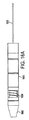
図17Aは、本発明のいくつかの実施形態による、リード線抜去デバイスと併用する拡張コンポーネントを例示している。図17において、拡張コンポーネントは、液圧または気体圧で操作することが可能なピストン機構を使用して、デバイスの一部分を伸長しリード線にそってデバイスを前進させやすくすることができる。拡張コンポーネントは、ピストン機構1720、内側チューブ1724、および端部1726を備えることができる。ピストン機構1720は、内側パーツ1720aおよび外側パーツ1720bからなるものとしてよい。内側パーツ1720aは、内側パーツ1720aが外側パーツ1720bから摺動して出入りすることができるように外側パーツ1720bに移動可能に結合されうる。流体圧力を、さらに膨張チューブに連結されうる孔1715を介してピストン機構に印加することができる。
FIG. 17A illustrates an expansion component for use with a lead extraction device, according to some embodiments of the present invention. In FIG. 17, the expansion component can use a piston mechanism that can be operated with hydraulic or gas pressure to extend a portion of the device and facilitate advancement of the device along the lead. The expansion component can include a
流体圧力がピストン機構1720に印加されると、内側パーツ1720aが矢印1706の方向に外側パーツ1720bから強制的に出される。内側パーツ1720aは、ピストン機構が膨らんだときに切断部分が前進するように切断部分または切断部分に結合された遠位部分に結合されうる。それに加えて、内側パーツ1720aは、ピストン機構が膨らんだときに回転コンポーネントにより切断部分が切断部分の前進運動と同時に、またはその前進運動とは独立して回転するように回転コンポーネントに結合されうる。ピストン機構は、ピストン機構が膨らんだときにバネ機構が引き伸ばされるようにバネ機構に結合されうる。ピストン機構が萎むと、バネは反動で静止位置に戻るものとしてよい。バネ機構が静止位置に戻る力は、内側パーツ1720aを強制的に外側パーツ1720bに戻すことができる(例えば、外側パーツ1720bを前方に引っ張ることによって)。
When fluid pressure is applied to
内側チューブ1724は、拡張部分を通してリード線を収容する実質的に剛性のあるチューブであるものとしてよい。端部1726は、流体圧力下で内側パーツ1720aの前進を停止するように配置されうる。拡張コンポーネントを単独で、または本明細書で説明されている他のコンポーネントのうちの1つもしくは組み合わせとともに使用して、リード線にそったリード線抜去デバイスの前進を容易にすることができることは理解されるであろう。本発明の態様は、特定の種類のピストン機構と併用することに限定されていないので、流体圧力を介して伸長する他のピストン機構を使用することができる。図17Bは、図17Aに例示されている拡張部分の断面を示しており、これは内側パーツ1720aが流体圧力下で摺動して外へ出ることを可能にするパーツ1722および1723を示している。それに加えて、パーツ1702cは、ピストン機構を膨らませるために膨張チューブが挿通されうる末端部1720cを示している。
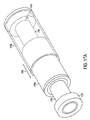
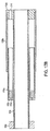
図18Aおよび18Bは、萎んだ状態のリード線抜去デバイスの拡張部分(両方とも通常図面と断面図)と膨らんだ状態のリード線抜去デバイスの拡張部分(両方とも通常図面と断面図)をそれぞれ例示している。拡張部分は、内側パーツ1820a、外側パーツ1820b、および末端部1820cからなるものとしてよいピストン機構1820を備える。ピストン機構は、内側パーツ1820aが流体圧力を印加された後に延出されうる限り、図17Aおよび17Bに関連して説明されているピストン機構と同様の、または異なる様式で動作することが可能である。図18Aに示されているように、拡張コンポーネントが萎んだ状態にある場合、内側パーツ1820aは、実質的に外側パーツ1820bの中にある。図18Bに示されているように、流体圧力によりピストン機構が膨らむと、内側パーツ1820aはリード線にそって強制的に外へ出される。他のパーツ、コンポーネント、および機構は、本発明の態様がこの点に限定されていないので、拡張部分に含まれうる。
18A and 18B illustrate an expanded portion of a lead extraction device in a deflated state (both normal drawing and sectional view) and an expanded portion of a lead extraction device in an expanded state (both normal drawing and sectional view), respectively doing. The expansion portion includes a piston mechanism 1820 that may consist of an
本発明の上述の実施形態は、多数ある方法のうちのどの方法でも実装することができ、本明細書で説明されている例は、限定的ではない。それに加えて、本発明のさまざまな態様は、単独で、組み合わせて、または前述の実施形態おいて特には説明されていないさまざまな配置構成で使用することができ、したがって、その応用に関して、前記の説明で述べた、または図面に例示されているコンポーネントの詳細および配置構成に限定されない。特に、固定すること、前進させること、および切断することに関係するさまざまな概念は、任意の形で実装し、また単独で、もしくは任意に組み合わせて使用することができる。本発明は、他の実施形態を利用することができ、またさまざまな方法で実施されるか、または実行されうる。 The above-described embodiments of the present invention can be implemented in any of a number of ways, and the examples described herein are not limiting. In addition, the various aspects of the present invention can be used alone, in combination, or in various arrangements not specifically described in the foregoing embodiments, and thus, with respect to its application, It is not limited to the details and arrangement of components mentioned in the description or illustrated in the drawings. In particular, the various concepts related to securing, advancing, and cutting can be implemented in any form and used alone or in any combination. The invention is capable of other embodiments and of being practiced or carried out in various ways.
請求要素を修飾するために請求項において「第1の」、「第2の」、「第3の」などの順序を示す語を使用しても、それ自体で、優先度、優先順位、または一方の請求要素が他方の請求要素より上であることを示す順序、または方法の各段階が実行される時間的順序を暗示することはなく、特定の名称を持つ一方の請求要素をそれと同じ名称を持つ他の要素から区別し(ただし順序を示す語を使用するために)、請求要素を区別するためのラベルとしてのみ使用される。 The use of a word indicating an order such as “first”, “second”, “third”, etc. in a claim to qualify the claim element itself is a priority, priority, or It does not imply the order in which one claim element is above the other claim element, or the temporal order in which the steps of the method are performed, and one claim element with a particular name will have the same name. It is used only as a label to distinguish billing elements from other elements that have a (but to use ordering words).
また、本明細書で使用される語法および術語は、説明を目的としたものであり、制限するものとしてみなされるべきではない。「含む、備える(including)」、「からなる、備える、含む(comprising)」、または「有する(having)」、「伴う(involving)」、および本明細書におけるそれらの変形は、それ以降に記載される項目および同等の項目、さらには追加項目を包含することを意味する。 Also, the terminology and terminology used herein is for the purpose of explanation and should not be regarded as limiting. “Including”, “consisting of, comprising”, or “having”, “involving”, and variations thereof herein are described below. It is meant to include the items to be processed and equivalent items, as well as additional items.
Claims (14)
前記リード線を収容するように適合された中心部を有する本体部分と、
前記リード線から組織を分離することを補助するために前記本体部分に結合された切断コンポーネントと、
少なくとも部分的に前記本体部分内に配設された少なくとも1つの固定コンポーネントであって、該固定コンポーネントの少なくとも一部は、流体圧力を印加することによって前記リード線にそって前記本体部分の少なくとも一部の移動に抵抗する圧力を前記リード線に加えることができる、固定コンポーネントと、からなるデバイスにおいて、
前記本体部分は、遠位部分と近位部分とを有し、
少なくとも1つの拡張コンポーネントをさらに備え、該拡張コンポーネントの少なくとも一部は、流体圧力を印加することによって前記遠位部分と前記近位部分との間の距離を変化させることができることを特徴とするデバイス。 A device for assisting in removing an implanted lead,
A body portion having a central portion adapted to receive the lead wire;
A cutting component coupled to the body portion to assist in separating tissue from the lead;
At least one securing component disposed at least partially within the body portion, wherein at least a portion of the securing component applies at least one of the body portions along the lead by applying fluid pressure. A device comprising a stationary component capable of applying pressure to the lead wire to resist movement of the part ;
The body portion has a distal portion and a proximal portion;
The device further comprising at least one dilation component, wherein at least a portion of the dilation component is capable of changing a distance between the distal portion and the proximal portion by applying fluid pressure. .
前記リード線を収容するように適合された中心部を有する本体部分と、
前記リード線から組織を分離することを補助するために前記本体部分に結合された切断コンポーネントと、
少なくとも部分的に前記本体部分内に配設された少なくとも1つの固定コンポーネントであって、該固定コンポーネントの少なくとも一部は、流体圧力を印加することによって前記リード線にそって前記本体部分の少なくとも一部の移動に抵抗する圧力を前記リード線に加えることができる、固定コンポーネントと、からなるデバイスにおいて、
前記少なくとも1つの固定コンポーネントは、少なくとも1つの拡張コンポーネントを備え、該少なくとも1つの拡張コンポーネントの少なくとも一部は、流体圧力を印加することによって前記リード線にそって前記本体部分の少なくとも一部を前進させることができることを特徴とするデバイス。 A device for assisting in removing an implanted lead,
A body portion having a central portion adapted to receive the lead wire;
A cutting component coupled to the body portion to assist in separating tissue from the lead;
At least one securing component disposed at least partially within the body portion, wherein at least a portion of the securing component applies at least one of the body portions along the lead by applying fluid pressure. A device comprising a stationary component capable of applying pressure to the lead wire to resist movement of the part;
The at least one stationary component comprises at least one expansion component, and at least a portion of the at least one expansion component advances at least a portion of the body portion along the lead by applying fluid pressure. A device characterized by being capable of being made.
The at least one anchoring component and the at least one dilation component are formed from a plurality of connected balloons, each of the plurality of connected balloons, when inflated, of the body portion along the lead. The device of claim 10 , wherein pressure that resists movement of at least a portion can be applied to the lead wire to advance at least a portion of the body portion along the lead wire.
該デバイスの中心部分を介して該リード線を収容するための手段と、
該リード線から組織を分離するための分離手段と、
少なくとも一部は流体圧力を印加することによって該リード線にそった該デバイスの少なくとも一部の移動に抵抗する圧力を該リード線に加えるための固定手段と、
少なくとも一部は流体圧力を印加することによって前記遠位部分と前記近位部分との間の距離を変化させることができる拡張手段と、
からなるデバイス。 A device comprising a body portion having a distal portion and a proximal portion for assisting in removing an implanted lead,
Means for receiving the lead wire through a central portion of the device;
Separating means for separating tissue from the lead;
A fixing means for applying pressure to resist the movement of at least a portion of the device along the said lead wire by applying fluid pressure to said lead wire at least in part,
Expansion means capable of changing a distance between the distal portion and the proximal portion by applying fluid pressure at least in part;
A device consisting of
Applications Claiming Priority (3)
| Application Number | Priority Date | Filing Date | Title |
|---|---|---|---|
| US14417609P | 2009-01-13 | 2009-01-13 | |
| US61/144,176 | 2009-01-13 | ||
| PCT/IB2010/000206 WO2010082139A1 (en) | 2009-01-13 | 2010-01-13 | Lead extraction methods and apparatus |
Related Child Applications (2)
| Application Number | Title | Priority Date | Filing Date |
|---|---|---|---|
| JP2014150596A Division JP2014237010A (en) | 2009-01-13 | 2014-07-24 | Method and device for pulling out lead wire |
| JP2014151209A Division JP5806371B2 (en) | 2009-01-13 | 2014-07-24 | Method and apparatus for removing lead wires |
Publications (3)
| Publication Number | Publication Date |
|---|---|
| JP2012515011A JP2012515011A (en) | 2012-07-05 |
| JP2012515011A5 JP2012515011A5 (en) | 2013-02-28 |
| JP5587910B2 true JP5587910B2 (en) | 2014-09-10 |
Family
ID=42040349
Family Applications (3)
| Application Number | Title | Priority Date | Filing Date |
|---|---|---|---|
| JP2011544948A Expired - Fee Related JP5587910B2 (en) | 2009-01-13 | 2010-01-13 | Method and apparatus for removing lead wires |
| JP2014151209A Expired - Fee Related JP5806371B2 (en) | 2009-01-13 | 2014-07-24 | Method and apparatus for removing lead wires |
| JP2014150596A Pending JP2014237010A (en) | 2009-01-13 | 2014-07-24 | Method and device for pulling out lead wire |
Family Applications After (2)
| Application Number | Title | Priority Date | Filing Date |
|---|---|---|---|
| JP2014151209A Expired - Fee Related JP5806371B2 (en) | 2009-01-13 | 2014-07-24 | Method and apparatus for removing lead wires |
| JP2014150596A Pending JP2014237010A (en) | 2009-01-13 | 2014-07-24 | Method and device for pulling out lead wire |
Country Status (10)
| Country | Link |
|---|---|
| US (3) | US9301773B2 (en) |
| EP (1) | EP2384153B1 (en) |
| JP (3) | JP5587910B2 (en) |
| CN (1) | CN102348422B (en) |
| AU (1) | AU2010205447B2 (en) |
| BR (1) | BRPI1006831A2 (en) |
| CA (1) | CA2749251C (en) |
| ES (1) | ES2546661T3 (en) |
| IL (1) | IL213963A (en) |
| WO (1) | WO2010082139A1 (en) |
Families Citing this family (38)
| Publication number | Priority date | Publication date | Assignee | Title |
|---|---|---|---|---|
| US9028520B2 (en) | 2006-12-22 | 2015-05-12 | The Spectranetics Corporation | Tissue separating systems and methods |
| US8961551B2 (en) | 2006-12-22 | 2015-02-24 | The Spectranetics Corporation | Retractable separating systems and methods |
| JP5587910B2 (en) * | 2009-01-13 | 2014-09-10 | リーデックス カーディアック リミテッド | Method and apparatus for removing lead wires |
| AU2012235868A1 (en) * | 2011-04-01 | 2013-05-09 | Leadex Cardiac Ltd. | Lead extraction methods and apparatus |
| EP2589348B1 (en) | 2011-11-03 | 2017-12-06 | VascoMed GmbH | Device for explanting electrode leads |
| US9413896B2 (en) * | 2012-09-14 | 2016-08-09 | The Spectranetics Corporation | Tissue slitting methods and systems |
| US9291663B2 (en) | 2013-03-13 | 2016-03-22 | The Spectranetics Corporation | Alarm for lead insulation abnormality |
| US9883885B2 (en) | 2013-03-13 | 2018-02-06 | The Spectranetics Corporation | System and method of ablative cutting and pulsed vacuum aspiration |
| US9456872B2 (en) | 2013-03-13 | 2016-10-04 | The Spectranetics Corporation | Laser ablation catheter |
| US9421035B2 (en) * | 2013-03-13 | 2016-08-23 | The Spectranetics Corporation | Method for lead tip removal using a stabilization device |
| US10383691B2 (en) | 2013-03-13 | 2019-08-20 | The Spectranetics Corporation | Last catheter with helical internal lumen |
| US9283040B2 (en) | 2013-03-13 | 2016-03-15 | The Spectranetics Corporation | Device and method of ablative cutting with helical tip |
| US10835279B2 (en) | 2013-03-14 | 2020-11-17 | Spectranetics Llc | Distal end supported tissue slitting apparatus |
| US9668765B2 (en) | 2013-03-15 | 2017-06-06 | The Spectranetics Corporation | Retractable blade for lead removal device |
| US10842532B2 (en) | 2013-03-15 | 2020-11-24 | Spectranetics Llc | Medical device for removing an implanted object |
| US10136913B2 (en) | 2013-03-15 | 2018-11-27 | The Spectranetics Corporation | Multiple configuration surgical cutting device |
| US9980743B2 (en) | 2013-03-15 | 2018-05-29 | The Spectranetics Corporation | Medical device for removing an implanted object using laser cut hypotubes |
| US10448999B2 (en) | 2013-03-15 | 2019-10-22 | The Spectranetics Corporation | Surgical instrument for removing an implanted object |
| WO2014151814A1 (en) | 2013-03-15 | 2014-09-25 | The Spectranetics Corporation | Surgical instrument for removing an implanted object |
| US9603618B2 (en) | 2013-03-15 | 2017-03-28 | The Spectranetics Corporation | Medical device for removing an implanted object |
| US10207105B2 (en) | 2013-08-25 | 2019-02-19 | Talpanetics bv | Extractor for removing a lead from a patient |
| US9889294B2 (en) | 2013-08-25 | 2018-02-13 | Talpanetics bv | Extractor for removing a lead from a patient |
| US10792490B2 (en) | 2013-11-12 | 2020-10-06 | Medtronic, Inc. | Open channel implant tools and implant techniques utilizing such tools |
| US10405924B2 (en) | 2014-05-30 | 2019-09-10 | The Spectranetics Corporation | System and method of ablative cutting and vacuum aspiration through primary orifice and auxiliary side port |
| JP3194755U (en) * | 2014-09-02 | 2014-12-11 | 嗣允 藤原 | Pacemaker lead sheath for peeling adhesion |
| US11083491B2 (en) | 2014-12-09 | 2021-08-10 | Medtronic, Inc. | Extravascular implant tools utilizing a bore-in mechanism and implant techniques using such tools |
| US10349978B2 (en) * | 2014-12-18 | 2019-07-16 | Medtronic, Inc. | Open channel implant tool with additional lumen and implant techniques utilizing such tools |
| USD765243S1 (en) | 2015-02-20 | 2016-08-30 | The Spectranetics Corporation | Medical device handle |
| USD770616S1 (en) | 2015-02-20 | 2016-11-01 | The Spectranetics Corporation | Medical device handle |
| US20170105762A1 (en) * | 2015-10-15 | 2017-04-20 | Medtronic Advanced Energy Llc | Lead extraction |
| WO2017180465A1 (en) * | 2016-04-15 | 2017-10-19 | University Of Floriada Research Foundation, Inc. | Removing electrical leads attached to the body by natural tissue growth |
| US10952785B2 (en) | 2016-08-01 | 2021-03-23 | Medtronic Advanced Energy, Llc | Device for medical lead extraction |
| CN109923081A (en) | 2016-11-14 | 2019-06-21 | 美敦力先进能量有限公司 | The glaze ceramic composite with controlled thermal expansion coefficient for electrosurgical tool |
| EP3456379B1 (en) * | 2017-09-15 | 2020-03-11 | Sorin CRM SAS | Explantation assembly for retrieving intracorporeal autonomous capsules |
| IL274764B1 (en) * | 2020-05-19 | 2024-04-01 | Xtrac O S Ltd | Vibration system and device for extraction of a lead of a cardiac implantable electronic device |
| CN112729995B (en) * | 2021-01-29 | 2023-09-22 | 徐州市检验检测中心 | Food inspection sampling device |
| CN116981496A (en) * | 2021-03-11 | 2023-10-31 | 皇家飞利浦有限公司 | System and apparatus for a non-invasive lead extraction tool with dual-action rotation and axial movement |
| WO2023212619A1 (en) * | 2022-04-27 | 2023-11-02 | Medtronic, Inc. | Material removal device for lead extraction preparation |
Family Cites Families (19)
| Publication number | Priority date | Publication date | Assignee | Title |
|---|---|---|---|---|
| US3763864A (en) * | 1971-10-29 | 1973-10-09 | G Dremann | Powered resectoscope |
| US4176662A (en) * | 1977-06-17 | 1979-12-04 | The United States Of America As Represented By The Administrator Of The National Aeronautics And Space Administration | Apparatus for endoscopic examination |
| US4429720A (en) * | 1982-09-23 | 1984-02-07 | Beck Richard D | Apparatus for seeking out and repairing leaks in pipes |
| US4576162A (en) * | 1983-03-30 | 1986-03-18 | Mccorkle Charles E | Apparatus and method for separation of scar tissue in venous pathway |
| US4848168A (en) * | 1987-04-13 | 1989-07-18 | Bridgestone Corporation | Traveling device moving along elongated member |
| JPS63255168A (en) * | 1987-04-13 | 1988-10-21 | 株式会社ブリヂストン | Pipe-outside running gear |
| US5013310A (en) * | 1988-11-09 | 1991-05-07 | Cook Pacemaker Corporation | Method and apparatus for removing an implanted pacemaker lead |
| US5398670A (en) * | 1993-08-31 | 1995-03-21 | Ethicon, Inc. | Lumen traversing device |
| US5651781A (en) * | 1995-04-20 | 1997-07-29 | Grace-Wells Technology Partners No. 1, L.P. | Surgical cutting instrument |
| US6764441B2 (en) * | 2001-09-17 | 2004-07-20 | Case Western Reserve University | Peristaltically self-propelled endoscopic device |
| EP1722696A1 (en) | 2004-02-27 | 2006-11-22 | Cook Vascular TM Incorporated | Device for removing an elongated structure implanted in biological tissue |
| US20060184063A1 (en) | 2005-02-15 | 2006-08-17 | Miller Michael E | Single motor handheld biopsy device |
| US20060253179A1 (en) * | 2005-04-15 | 2006-11-09 | Cook Vascular Incorporated | Tip for lead extraction device |
| JP5236472B2 (en) * | 2005-08-11 | 2013-07-17 | テクニオン リサーチ アンド ディベロップメント ファンデーション リミテッド | Tip propulsion device moving through a passage |
| US9028520B2 (en) | 2006-12-22 | 2015-05-12 | The Spectranetics Corporation | Tissue separating systems and methods |
| ATE472294T1 (en) | 2007-05-09 | 2010-07-15 | Jaak Ph Janssens | ARRANGEMENT OF MEDICAL TOOLS |
| US20090030436A1 (en) | 2007-07-27 | 2009-01-29 | Charles Steven T | Hydraulic acuation for microsurgical instruments |
| US8313493B2 (en) * | 2008-07-10 | 2012-11-20 | Cook Medical Technologies Llc | Hydraulic guidewire advancement system |
| JP5587910B2 (en) * | 2009-01-13 | 2014-09-10 | リーデックス カーディアック リミテッド | Method and apparatus for removing lead wires |
-
2010
- 2010-01-13 JP JP2011544948A patent/JP5587910B2/en not_active Expired - Fee Related
- 2010-01-13 CN CN201080011758.5A patent/CN102348422B/en not_active Expired - Fee Related
- 2010-01-13 AU AU2010205447A patent/AU2010205447B2/en not_active Ceased
- 2010-01-13 WO PCT/IB2010/000206 patent/WO2010082139A1/en active Application Filing
- 2010-01-13 BR BRPI1006831A patent/BRPI1006831A2/en not_active Application Discontinuation
- 2010-01-13 ES ES10705418.1T patent/ES2546661T3/en active Active
- 2010-01-13 CA CA2749251A patent/CA2749251C/en not_active Expired - Fee Related
- 2010-01-13 US US12/686,572 patent/US9301773B2/en active Active
- 2010-01-13 EP EP10705418.1A patent/EP2384153B1/en not_active Not-in-force
-
2011
- 2011-07-06 IL IL213963A patent/IL213963A/en not_active IP Right Cessation
-
2014
- 2014-07-24 JP JP2014151209A patent/JP5806371B2/en not_active Expired - Fee Related
- 2014-07-24 JP JP2014150596A patent/JP2014237010A/en active Pending
-
2015
- 2015-10-02 US US14/873,872 patent/US20160022302A1/en not_active Abandoned
-
2016
- 2016-09-12 US US15/262,793 patent/US20160374721A1/en not_active Abandoned
Also Published As
| Publication number | Publication date |
|---|---|
| CN102348422B (en) | 2015-11-25 |
| CN102348422A (en) | 2012-02-08 |
| JP2014221411A (en) | 2014-11-27 |
| US20100198229A1 (en) | 2010-08-05 |
| BRPI1006831A2 (en) | 2016-04-12 |
| US20160022302A1 (en) | 2016-01-28 |
| CA2749251C (en) | 2018-07-03 |
| JP5806371B2 (en) | 2015-11-10 |
| IL213963A0 (en) | 2011-08-31 |
| US9301773B2 (en) | 2016-04-05 |
| ES2546661T3 (en) | 2015-09-25 |
| IL213963A (en) | 2015-04-30 |
| US20160374721A1 (en) | 2016-12-29 |
| JP2012515011A (en) | 2012-07-05 |
| WO2010082139A1 (en) | 2010-07-22 |
| AU2010205447B2 (en) | 2015-07-30 |
| CA2749251A1 (en) | 2010-07-22 |
| JP2014237010A (en) | 2014-12-18 |
| EP2384153A1 (en) | 2011-11-09 |
| AU2010205447A1 (en) | 2011-07-28 |
| EP2384153B1 (en) | 2015-06-03 |
Similar Documents
| Publication | Publication Date | Title |
|---|---|---|
| JP5806371B2 (en) | Method and apparatus for removing lead wires | |
| JP6292487B2 (en) | Device for positioning electrodes in tissue | |
| US9320875B2 (en) | Systems for implanting and using a conduit within a tissue wall | |
| US10398470B2 (en) | Lead extraction methods and apparatus | |
| JP5912198B2 (en) | Endocardial device delivery system and system for reducing the effective volume of the ventricle | |
| CA2938371A1 (en) | Apparatus using branched balloon for treating pulmonary arterial hypertension | |
| WO2014083559A1 (en) | Vascular occluding device and methods of use | |
| US10251768B2 (en) | Intragastric balloon retrieval systems and related methods | |
| WO2011146085A1 (en) | Rapid response balloon catheter |
Legal Events
| Date | Code | Title | Description |
|---|---|---|---|
| A521 | Request for written amendment filed |
Free format text: JAPANESE INTERMEDIATE CODE: A523 Effective date: 20130110 |
|
| A621 | Written request for application examination |
Free format text: JAPANESE INTERMEDIATE CODE: A621 Effective date: 20130110 |
|
| A131 | Notification of reasons for refusal |
Free format text: JAPANESE INTERMEDIATE CODE: A131 Effective date: 20131210 |
|
| A977 | Report on retrieval |
Free format text: JAPANESE INTERMEDIATE CODE: A971007 Effective date: 20131213 |
|
| A601 | Written request for extension of time |
Free format text: JAPANESE INTERMEDIATE CODE: A601 Effective date: 20140305 |
|
| A602 | Written permission of extension of time |
Free format text: JAPANESE INTERMEDIATE CODE: A602 Effective date: 20140312 |
|
| A521 | Request for written amendment filed |
Free format text: JAPANESE INTERMEDIATE CODE: A523 Effective date: 20140603 |
|
| TRDD | Decision of grant or rejection written | ||
| A01 | Written decision to grant a patent or to grant a registration (utility model) |
Free format text: JAPANESE INTERMEDIATE CODE: A01 Effective date: 20140624 |
|
| A61 | First payment of annual fees (during grant procedure) |
Free format text: JAPANESE INTERMEDIATE CODE: A61 Effective date: 20140724 |
|
| R150 | Certificate of patent or registration of utility model |
Ref document number: 5587910 Country of ref document: JP Free format text: JAPANESE INTERMEDIATE CODE: R150 |
|
| R250 | Receipt of annual fees |
Free format text: JAPANESE INTERMEDIATE CODE: R250 |
|
| R250 | Receipt of annual fees |
Free format text: JAPANESE INTERMEDIATE CODE: R250 |
|
| LAPS | Cancellation because of no payment of annual fees |