JP5587879B2 - Method for operating a motorcycle control system - Google Patents
Method for operating a motorcycle control system Download PDFInfo
- Publication number
- JP5587879B2 JP5587879B2 JP2011517174A JP2011517174A JP5587879B2 JP 5587879 B2 JP5587879 B2 JP 5587879B2 JP 2011517174 A JP2011517174 A JP 2011517174A JP 2011517174 A JP2011517174 A JP 2011517174A JP 5587879 B2 JP5587879 B2 JP 5587879B2
- Authority
- JP
- Japan
- Prior art keywords
- operating
- lock
- control system
- actuating
- authentication
- Prior art date
- Legal status (The legal status is an assumption and is not a legal conclusion. Google has not performed a legal analysis and makes no representation as to the accuracy of the status listed.)
- Expired - Fee Related
Links
- 238000000034 method Methods 0.000 title claims description 105
- 230000008569 process Effects 0.000 claims description 74
- 230000005540 biological transmission Effects 0.000 claims description 25
- 238000001994 activation Methods 0.000 claims description 19
- 230000000452 restraining effect Effects 0.000 claims description 13
- 230000033001 locomotion Effects 0.000 claims description 11
- 230000004913 activation Effects 0.000 claims description 8
- 230000007246 mechanism Effects 0.000 claims description 8
- 238000013459 approach Methods 0.000 claims description 7
- 230000001939 inductive effect Effects 0.000 claims description 2
- 230000004308 accommodation Effects 0.000 description 9
- 230000001419 dependent effect Effects 0.000 description 2
- 230000009471 action Effects 0.000 description 1
- 230000003213 activating effect Effects 0.000 description 1
- 239000012190 activator Substances 0.000 description 1
- 238000004891 communication Methods 0.000 description 1
- 238000012790 confirmation Methods 0.000 description 1
- 238000013461 design Methods 0.000 description 1
- 238000010586 diagram Methods 0.000 description 1
- 230000000694 effects Effects 0.000 description 1
- 230000001976 improved effect Effects 0.000 description 1
- 230000003287 optical effect Effects 0.000 description 1
- 239000011435 rock Substances 0.000 description 1
- 230000008054 signal transmission Effects 0.000 description 1
- 230000001960 triggered effect Effects 0.000 description 1
Images


Classifications
-
- B—PERFORMING OPERATIONS; TRANSPORTING
- B60—VEHICLES IN GENERAL
- B60R—VEHICLES, VEHICLE FITTINGS, OR VEHICLE PARTS, NOT OTHERWISE PROVIDED FOR
- B60R25/00—Fittings or systems for preventing or indicating unauthorised use or theft of vehicles
- B60R25/01—Fittings or systems for preventing or indicating unauthorised use or theft of vehicles operating on vehicle systems or fittings, e.g. on doors, seats or windscreens
- B60R25/02—Fittings or systems for preventing or indicating unauthorised use or theft of vehicles operating on vehicle systems or fittings, e.g. on doors, seats or windscreens operating on the steering mechanism
- B60R25/021—Fittings or systems for preventing or indicating unauthorised use or theft of vehicles operating on vehicle systems or fittings, e.g. on doors, seats or windscreens operating on the steering mechanism restraining movement of the steering column or steering wheel hub, e.g. restraining means controlled by ignition switch
- B60R25/02147—Fittings or systems for preventing or indicating unauthorised use or theft of vehicles operating on vehicle systems or fittings, e.g. on doors, seats or windscreens operating on the steering mechanism restraining movement of the steering column or steering wheel hub, e.g. restraining means controlled by ignition switch comprising a locking member having other than linear, axial or radial motion, e.g. rotatable; Steering column locking using balls, rollers or the like
-
- B—PERFORMING OPERATIONS; TRANSPORTING
- B60—VEHICLES IN GENERAL
- B60R—VEHICLES, VEHICLE FITTINGS, OR VEHICLE PARTS, NOT OTHERWISE PROVIDED FOR
- B60R25/00—Fittings or systems for preventing or indicating unauthorised use or theft of vehicles
- B60R25/01—Fittings or systems for preventing or indicating unauthorised use or theft of vehicles operating on vehicle systems or fittings, e.g. on doors, seats or windscreens
- B60R25/02—Fittings or systems for preventing or indicating unauthorised use or theft of vehicles operating on vehicle systems or fittings, e.g. on doors, seats or windscreens operating on the steering mechanism
- B60R25/021—Fittings or systems for preventing or indicating unauthorised use or theft of vehicles operating on vehicle systems or fittings, e.g. on doors, seats or windscreens operating on the steering mechanism restraining movement of the steering column or steering wheel hub, e.g. restraining means controlled by ignition switch
- B60R25/0215—Fittings or systems for preventing or indicating unauthorised use or theft of vehicles operating on vehicle systems or fittings, e.g. on doors, seats or windscreens operating on the steering mechanism restraining movement of the steering column or steering wheel hub, e.g. restraining means controlled by ignition switch using electric means, e.g. electric motors or solenoids
- B60R25/02153—Fittings or systems for preventing or indicating unauthorised use or theft of vehicles operating on vehicle systems or fittings, e.g. on doors, seats or windscreens operating on the steering mechanism restraining movement of the steering column or steering wheel hub, e.g. restraining means controlled by ignition switch using electric means, e.g. electric motors or solenoids comprising a locking member radially and linearly moved towards the steering column
-
- B—PERFORMING OPERATIONS; TRANSPORTING
- B60—VEHICLES IN GENERAL
- B60R—VEHICLES, VEHICLE FITTINGS, OR VEHICLE PARTS, NOT OTHERWISE PROVIDED FOR
- B60R25/00—Fittings or systems for preventing or indicating unauthorised use or theft of vehicles
- B60R25/01—Fittings or systems for preventing or indicating unauthorised use or theft of vehicles operating on vehicle systems or fittings, e.g. on doors, seats or windscreens
- B60R25/04—Fittings or systems for preventing or indicating unauthorised use or theft of vehicles operating on vehicle systems or fittings, e.g. on doors, seats or windscreens operating on the propulsion system, e.g. engine or drive motor
-
- B—PERFORMING OPERATIONS; TRANSPORTING
- B60—VEHICLES IN GENERAL
- B60R—VEHICLES, VEHICLE FITTINGS, OR VEHICLE PARTS, NOT OTHERWISE PROVIDED FOR
- B60R25/00—Fittings or systems for preventing or indicating unauthorised use or theft of vehicles
- B60R25/20—Means to switch the anti-theft system on or off
- B60R25/2063—Ignition switch geometry
-
- B—PERFORMING OPERATIONS; TRANSPORTING
- B60—VEHICLES IN GENERAL
- B60R—VEHICLES, VEHICLE FITTINGS, OR VEHICLE PARTS, NOT OTHERWISE PROVIDED FOR
- B60R25/00—Fittings or systems for preventing or indicating unauthorised use or theft of vehicles
- B60R25/20—Means to switch the anti-theft system on or off
- B60R25/24—Means to switch the anti-theft system on or off using electronic identifiers containing a code not memorised by the user
- B60R25/243—Means to switch the anti-theft system on or off using electronic identifiers containing a code not memorised by the user with more than one way to gain access
-
- B—PERFORMING OPERATIONS; TRANSPORTING
- B60—VEHICLES IN GENERAL
- B60R—VEHICLES, VEHICLE FITTINGS, OR VEHICLE PARTS, NOT OTHERWISE PROVIDED FOR
- B60R2325/00—Indexing scheme relating to vehicle anti-theft devices
- B60R2325/30—Vehicles applying the vehicle anti-theft devices
- B60R2325/306—Motorcycles
-
- Y—GENERAL TAGGING OF NEW TECHNOLOGICAL DEVELOPMENTS; GENERAL TAGGING OF CROSS-SECTIONAL TECHNOLOGIES SPANNING OVER SEVERAL SECTIONS OF THE IPC; TECHNICAL SUBJECTS COVERED BY FORMER USPC CROSS-REFERENCE ART COLLECTIONS [XRACs] AND DIGESTS
- Y10—TECHNICAL SUBJECTS COVERED BY FORMER USPC
- Y10T—TECHNICAL SUBJECTS COVERED BY FORMER US CLASSIFICATION
- Y10T70/00—Locks
- Y10T70/50—Special application
- Y10T70/5889—For automotive vehicles
- Y10T70/5956—Steering mechanism with switch
Landscapes
- Engineering & Computer Science (AREA)
- Mechanical Engineering (AREA)
- Lock And Its Accessories (AREA)
Description
本発明は、電気機械式ステアリングロックをロック解除位置からロック位置へ、またはその逆方向へと動かす自動二輪車の制御システムを操作する方法であって、制御システムによって制御され、自動二輪車のエンジンを始動させる点火システムを有するとともに、ID生成装置によって制御システムとのデータリンクを保持する認証を有し、操作ステップにおいて、認証に成功した後に、ステアリングロックを適切な位置へと導く方法に関する。 The present invention is a method for operating a motorcycle control system that moves an electromechanical steering lock from an unlocked position to a locked position or vice versa, and is controlled by the control system to start a motorcycle engine. And a method for guiding the steering lock to an appropriate position after successful authentication in an operating step, having an authentication system for holding and a data link with a control system by an ID generator.
独国特許公開公報第10049442(A1)号では、自動二輪車のエンジンを点火する前にアクセス権を確立する方法が開示されている。自動二輪車の両ハンドルバーにある始動ボタンを作動させると、認証プロセスが設定され、認証プロセスによりリクエスト信号が自動二輪車からID生成装置へと送信される。ID生成装置が有効であると認識された場合、すなわち、認証プロセスが成功、つまりID生成装置の電子コードが自動二輪車のコードに一致した場合には、ステアリングロック、具体的には電気機械式発進ロック(elektromechanische Wegfahrsperre)の機能が停止される。しかし、事例の中には、認証に成功したにもかかわらず、使用者が直接操作を行わないロック解除機能ステップやロック機能ステップがあるのは望ましくないことが示されたものもあった。その例としては、自動二輪車のエンジンを切って乗用者が自動二輪車から降車した後も、例えば乗用者が二輪車を最終的な駐車位置、具体的にはガレージまで、エンジンを切った状態で数フィート移動させなければならないために、自動二輪車が例えばロック解除位置となったままであってほしい場合である。 German Patent Publication No. 10049442 (A1) discloses a method for establishing an access right before the motorcycle engine is ignited. When the start button on both the handlebars of the motorcycle is operated, an authentication process is set, and a request signal is transmitted from the motorcycle to the ID generation device by the authentication process. If the ID generator is recognized as valid, i.e. the authentication process is successful, i.e. if the electronic code of the ID generator matches the motorcycle code, the steering lock, specifically the electromechanical start The lock (elektromechanische Wegfahrsperre) is deactivated. However, in some cases, it has been shown that it is not desirable that there is an unlock function step or a lock function step in which the user does not directly operate despite successful authentication. For example, even after the motorcycle is turned off and the passenger gets off the motorcycle, the passenger turns off the motorcycle for a few feet with the engine off, for example, to the final parking position, specifically to the garage. This is the case when it is desired to keep the motorcycle in the unlocked position, for example, because it must be moved.
本発明の目的は、電磁式ステアリングロックを適切な位置に動かすために、自動二輪車の制御システムを操作する方法を確立すること、及び、上記で示された難点を回避することで、ステアリングロックの適用範囲を広げる関連システムを提供することである。 It is an object of the present invention to establish a method for operating a motorcycle control system to move an electromagnetic steering lock to an appropriate position, and to avoid the drawbacks indicated above, To provide a related system that expands the scope of application.
この課題の解決手段として、請求項1の特徴を有する方法を提案する。その従属請求項には、好適な設計上の改善点が示されている。
本発明の精神においては、制御システムと信号接続の状態にあり、使用者が利用可能な第1作動要素を備えており、認証が成功した後にのみ、認証後に起こる、前記第1作動要素の意図的な稼動(Activierung)によって操作ステップが開始されることを特徴とする本方法が提供される。この認証は、意図せずに開始され得るだけではなく、第1作動要素を介して意図的に稼動させることによっても開始され得る。ID生成装置を有する使用者が自動二輪車から所定の距離の近辺にいるならば、ID生成装置と自動二輪車との間で双方向通信リンクが確立され、具体的には制御システム及び/または電気機械式ステアリングロックとの間で、ID生成装置の電子コードが自動二輪車に保存されている電子コードにどの程度一致するかが照合される。この状況において、双方向リンクは、光学式手法、誘導式手法、もしくは容量式手法、または無線信号伝送による別の手法で実行され得る。一旦認証成功が確立されると、今後、実際の作動ステップ、具体的にはロック機能またはロック解除機能を意図的に開始しなければならないのは使用者である。認証プロセスの成功後に使用者が作動要素を稼動させない場合は、ステアリングロックは現状の位置のままである。ステアリングロックは現状の位置のままであることは、自動二輪車のエンジンが既に切られていて、使用者が作動要素を単独で稼動させない場合、自動二輪車のステアリングロックはロック解除位置のままであることを意味している。この例の意味では、自動二輪車のエンジンを始動させる間、認証プロセスが所定の時間間隔で常に行われていることを付け加える必要がある。
As a means for solving this problem, a method having the features of
In the spirit of the invention, the intent of the first actuating element, which is in signal connection with the control system and comprises a first actuating element available to the user and which occurs after authentication only after successful authentication. A method is provided, characterized in that the operating step is initiated by an activator. This authentication can be initiated not only unintentionally, but can also be initiated by deliberately operating via the first actuating element. If the user having the ID generation device is in the vicinity of a predetermined distance from the motorcycle, a two-way communication link is established between the ID generation device and the motorcycle, specifically, the control system and / or the electric machine. The electronic code of the ID generating device is compared with the electronic code stored in the motorcycle with the type steering lock. In this situation, the bi-directional link may be implemented in an optical approach, an inductive approach, or a capacitive approach, or another approach with wireless signal transmission. Once successful authentication is established, it is the user who has to intentionally start the actual operational steps, specifically the lock or unlock function. If the user does not activate the actuating element after a successful authentication process, the steering lock remains in its current position. The steering lock remains in its current position, meaning that the motorcycle's steering lock remains in the unlocked position if the motorcycle engine is already turned off and the user does not operate the actuating element alone. Means. In the sense of this example, it is necessary to add that the authentication process is always carried out at predetermined time intervals while starting the motorcycle engine.
本発明の好適な実施形態において、作動プロセス後に、第2作動要素を新たに(erneute)意図的に稼動させることによって、待機プロセスが開始され、ここでステアリングロックは既にロック解除位置へと導かれているとともに、自動二輪車の点火システムの電力が使用可能になっていて、第3作動要素を新たに稼動させることによって、具体的にはエンジン点火プロセスを稼動させる。作動プロセス後に、第2作動要素および第3作動要素を新たに稼動させることは、使用者がそれぞれの作動要素を2回作動することによって、エンジン点火プロセスを開始可能であることを意味する。 In a preferred embodiment of the invention, after the actuating process, the waiting process is started by intentionally actuating the second actuating element, where the steering lock is already brought into the unlocked position. In addition, the electric power of the ignition system of the motorcycle is available, and specifically, the engine ignition process is operated by newly operating the third operating element. Running the second and third actuating elements anew after the actuating process means that the user can initiate the engine ignition process by actuating each actuating element twice.
作動プロセスの間に、制御システムは、ステアリング部の要求される位置に対する実際の位置を確認し、実際の位置が要求される位置に一致する場合は、ステアリングロックをロック解除位置からロック位置へと導くことが好ましい。もし実際の位置が要求される位置と違うならば、作動プロセス、具体的にはロック動作プロセスが中断される。作動プロセスを中断する場合、使用者はステアリング部の誤った位置についてのフィードバックメッセージを受信することが実行可能である。例えば、このフィードバックメッセージはステアリング部にあるディスプレイ装置によって生成可能である。また、音によるフィードバックメッセージも考えられる。ステアリング部のハンドルバーが所定のハンドルバー回転位置には位置していない場合は、ステアリングロックをロック解除位置からロック位置へと動かすことは行われない。例えば、この確認は、制御システムとのデータリンクを有するキャリパ素子、センサ等によって実行される。 During the actuation process, the control system checks the actual position relative to the required position of the steering part and if the actual position matches the required position, the steering lock is moved from the unlocked position to the locked position. It is preferable to guide. If the actual position is different from the required position, the activation process, specifically the locking operation process, is interrupted. When interrupting the activation process, the user can receive a feedback message about the wrong position of the steering part. For example, the feedback message can be generated by a display device in the steering unit. Also, sound feedback messages can be considered. When the handlebar of the steering unit is not located at the predetermined handlebar rotation position, the steering lock is not moved from the unlocked position to the locked position. For example, this confirmation is performed by a caliper element, a sensor or the like having a data link with the control system.
本発明の別の好適な実施形態によれば、(エンジンが稼働中における)エンジン停止プロセスは、第4作動要素を意図的に稼動させることによって起動され、点火部の制御システムが電力供給を遮断する。この場合、エンジン停止プロセスは、制御システムによって監視される、自動二輪車の所定の状況下で起動される。あり得る状況としては、例えば、自動二輪車の速度が0km/hを示すことになる、すなわち、停止状態である。エンジン停止の後に第5作動要素を新たに稼動させることにより、実装電子機器の電源を遮断するが、電源の遮断は例えばディスプレイ電子機器が停止することによって実証される。自動二輪車はこの時、エンジンが停止して「残りの電子機器」だけに電力を供給していて、その電力は例えばまだアクティブな認証プロセスに供給されているような状態か、もしくは、ステアリング装置に電力を供給しているような状態になっている。この時、ステアリングロックはまだロック解除位置にある。ここで、使用者は、第1作動要素または第2作動要素を別途稼動させてプロセスを作動させることによって、ステアリングロックをロック位置へと動かすことができる。 According to another preferred embodiment of the present invention, the engine shutdown process (while the engine is running) is activated by intentionally operating the fourth operating element and the ignition control system shuts off the power supply. To do. In this case, the engine stop process is started under a predetermined situation of the motorcycle monitored by the control system. As a possible situation, for example, the speed of the motorcycle will show 0 km / h, that is, it is in a stopped state. The power supply of the mounted electronic device is cut off by newly operating the fifth operating element after the engine is stopped. The power supply cut-off is demonstrated, for example, when the display electronic device is stopped. At this time, the motorcycle has stopped and is supplying power only to the “remaining electronics”, and that power is still being supplied to the active authentication process, for example, or to the steering device. It is in a state where power is being supplied. At this time, the steering lock is still in the unlocked position. Here, the user can move the steering lock to the locked position by separately operating the first operating element or the second operating element to operate the process.
第1作動要素、第2作動要素、及び第4作動要素は、中心作動要素を共に構成することが好ましく、これにより、中心作動要素はステアリング部にあるので、使用者が自由に利用可能となる。この対象となる作動要素は、キャリパ(Taster)、スイッチ、動作センサ、または接触センサ等として設計可能である。さらに、作動プロセス及び待機プロセスを始動するための中心作動要素の各作動時間は互いに異なり得る。また、作動プロセスの作動時間と実装電子機器の電源遮断時間は互いに異なり得る。これは、例えば、中心作動要素を長い時間作動させると作動プロセスを引き起こすことが可能であることを意味する。一方、中心作動要素を短い時間作動させると、待機プロセスもしくは実装電子機器の電源の遮断を引き起こすことが可能である。短い時間の作動と長い時間の作動を識別するために、中心作動要素にある種々のセンサ、具体的には容量センサ及び圧電センサが使用可能である。作動プロセス後、中心作動要素の稼動または作動要素のうちの1つの要素の稼動が所定の時間枠以内に起こらない場合は、制御システムは待機モードに切り替わる。 The first actuating element, the second actuating element, and the fourth actuating element preferably form a central actuating element together, so that the central actuating element is in the steering section so that it is freely available to the user. . The target actuating element can be designed as a caliper (Taster), switch, motion sensor, contact sensor or the like. Furthermore, the operating times of the central operating element for starting the operating process and the standby process can be different from each other. Further, the operation time of the operation process and the power-off time of the mounted electronic device may be different from each other. This means that, for example, operating the central actuating element for a long time can cause an actuating process. On the other hand, if the central operating element is operated for a short time, it is possible to cause the standby process or the power supply of the mounted electronic device to be cut off. In order to distinguish between short time and long time operation, various sensors in the central operating element can be used, specifically capacitive sensors and piezoelectric sensors. After the activation process, if the activation of the central activation element or one of the activation elements does not occur within a predetermined time frame, the control system switches to the standby mode.
さらに、本発明の目的は、ステアリングロックを制御するための機構であり、自動二輪車の機能に不可欠な構造部、具体的にはステアリングコラムのロック部材を有するとともに、ロック部材と機械的に有効に接続した状態で位置している歯車駆動部(Getriebe)を有し、作動プロセスの間、ロック部材はロック位置とロック解除位置の間で可動であり、ID生成装置が制御システムとのデータリンクを保持している認証プロセスを有し、認証の成功後、作動ステップでは、ステアリングロックを各位置へと導くことが可能で、その間、ロック位置ではロック部材が機能に不可欠な構造部と噛み合い、ロック解除位置ではロック部材が機能に不可欠な構造部から外され、使用者が利用するための作動要素が設けられていて、これにより、作動要素を意図的に稼動させることによって作動プロセスが開始される機構によって実現される。本発明によれば、制御システムは、ステアリングロックとのデータリンクを、認証の成功後に行われる作動要素の意図的な稼動によってのみで作動プロセスが起動されるような方法で保持している。従属請求項18〜21には、好適な改良実施形態が記述されている。 Furthermore, an object of the present invention is a mechanism for controlling the steering lock, which has a structural part indispensable for the function of the motorcycle, specifically, a steering column lock member, and is mechanically effective with the lock member. It has a gear drive (Getriebe) located in a connected state, and during the operating process, the locking member is movable between a locked position and an unlocked position, and the ID generating device provides a data link with the control system. It has a holding authentication process, and after successful authentication, the steering step can guide the steering lock to each position, during which the locking member engages with the structure essential to the function and locks In the release position, the locking member is removed from the structural part indispensable for the function, and an operating element is provided for use by the user. Is realized by a mechanism operating process is initiated by intentionally operating the. According to the invention, the control system maintains the data link with the steering lock in such a way that the operating process is activated only by intentional activation of the operating element after successful authentication. The dependent claims 18 to 21 describe preferred improved embodiments.
本発明の他の効果、特徴、及び詳細は、以下の説明から導き出され得るものであり、この説明では、本発明が採り得る実施形態の形式を図面を参照して記述している。この意味では、各請求項や本説明において示された特徴は、単独の構成であっても、またはいかなる所望の組み合わせであっても、発明に関連したものであり得る。 Other advantages, features and details of the invention can be derived from the following description, which describes the form of embodiments that the invention can take with reference to the drawings. In this sense, the features set forth in the claims and the description may be relevant to the invention, whether in a single configuration or in any desired combination.
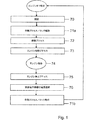
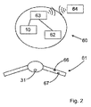
図1は、自動二輪車の制御システム63を操作して、図5〜12に示した電気機械式ステアリングロック10をロック解除位置2からロック位置1へと動かす、本発明に関連した方法の簡略化された説明を、単に概略的に示したものである。図1は、自動二輪車60(図2参照)のエンジンが停止している状態を想定している。ID生成装置64を有する使用者の可能性がある者(自動二輪車の乗り手)が自動二輪車60に近づくと、自動二輪車60から所定の距離で「自動的に」認証70が開始され、ID生成装置64に含まれているコードと自動二輪車が有するコードとがどの程度一致するかを照合する。認証70のプロセスは、例えば、自動二輪車のスタンドを動かしたり、自動二輪車のシートに接触したりすること等によって、意図したわけではないのに起動し得る。また、例えば、後に説明されるスイッチやキャリパ、またはエンジン始動スイッチの作動などの意図的な動作によって、認証70が開始されることも考えられる。ID生成装置64は、自動二輪車60の制御システム63とのデータリンクを保持している。さらに、制御システム63は、電気機械式ステアリングロック10との信号接続、及び、自動二輪車60のエンジンを始動させる点火システム62との信号接続を保持している。
FIG. 1 is a simplified illustration of the method associated with the present invention for operating a
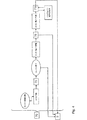
認証70が成功した後には、図3及び図4の方法図に概略的に示された作動プロセス71a,71bが、制御システム63との信号接続を保持する作動要素31を稼動させることによって開始可能である。作動プロセス71a,71bの間に、ステアリングロック10がロック解除位置2からロック位置1へ、またはその逆方向へと導かれるが、その詳細は図7〜12に図示されている。ここに示された実施例によれば、作動要素31は自動二輪車60のステアリング部61に配置されている(図2参照)。自動二輪車60をロック解除するために、使用者は、認証70の成功後に、作動要素31を意図的に稼動させなければならず、それによってステアリングロック10を適切に制御できる。本実施例では、ステアリングロック10を解除する作動プロセス71aは、作動要素31を長めに作動させることによって開始する。図3において、制御システム63はまず、ステアリングロック10がロック解除位置2に位置しているか、それともロック位置1に位置しているかを確認する。ステアリングロック10がロック位置2にある場合は、ステアリングロック10のロック解除機能71aを実行する。
After
待機プロセス72は、上述の作動プロセス71aの後に、作動要素61を新たに意図的に稼動させることによって開始され、このプロセス中に点火システム62によって動力が供給される。ステアリングロック10を解除する上述の作動プロセス71aを開始させるのに要する作動時間と比べると、待機プロセス72を稼動させる作動時間の方が短い。図2にあるエンジン始動スイッチ66を新たに始動させることにより、エンジン始動プロセス73が稼動する。
The
図3に図示されているように、認証70のプロセスはある時間間隔、すなわち、作動プロセス71a,71b、待機プロセス72、エンジン始動プロセス73、及び自動二輪車60のエンジンが稼働中の間の時間間隔で、繰り返し実行される。
As illustrated in FIG. 3, the process of
実施例において、作動プロセス71a,71bの間に、制御システム63は、ステアリングロック10の位置をステアリングロック10の現状の位置によって変化させる。これは、作動プロセス71a,71bを開始する作動要素31の稼働中に、制御システム63はまず、ステアリングロック10の現在の位置が位置1,2のうちのいずれの位置にあるのかを確認することを意味する。ステアリングロック10がロック位置1にある場合はロック解除が行われ、一方、ステアリングロック10がロック解除位置2にある場合はロック動作が行われる。ロック機能の作動プロセス71bは、作動プロセス71bの間に、制御システム63が制御部61の要求される位置に対する現在の位置を確認するという方法で実行される。現在の位置が要求される位置に一致すれば、ステアリングロック10はロック解除位置2からロック位置1へと導かれる。一方、現在の位置が要求される位置と一致しなければ、作動プロセス71bは中断され、使用者は、現状ではステアリング部61が誤った位置にあるという情報またはフィードバックを受信する(図3参照)。したがって、ロック機能は、ステアリング部61が所定の位置で静止している時にのみ行われる。
In the embodiment, during the operation processes 71 a and 71 b, the
自動二輪車60の駆動中のエンジンを停止させるためには、非常スイッチ67を意図的に稼動させることが必要になる(図2参照)。この場合、点火システム62の制御システム63は動力供給を遮断する。これによりエンジンが停止状態になるが、ここでエンジン停止措置75は、制御システム63によって監視される所定の自動二輪車の状況下でのみ実施可能となる。図4において、エンジン停止措置75が正常に行われると、作動要素31を新たに稼動させることによる、実装電子機器76の電源の遮断が可能となる。その後、所望であれば、使用者はステアリングロック10をロックする作動プロセス71bを、作動要素31を新たにより長く稼動させることで開始してもよい。同時に、ステアリング部61がそれぞれにおいて要求される位置をどの程度示しているかについての確認が実行される。図4に図示されているように、エンジン停止措置75の間、実装電子機器76の電源遮断中、及びステアリングロック10をロックする作動プロセス71bの間において、制御システム63によって認証70が繰り返される。図3及び図4に示すように、適切な作動要素が対応して稼動しなかった場合、制御システム63は休止モード77に切り替わることができる。プロセスが休止モード77になっている場合は、繰り返され続けている認証プロセスは行われない。
In order to stop the engine that is driving the
図7〜12は、上述したプロセスによって制御されるステアリングロック10の採り得る実施例を図示したものである。ステアリングロック10は、機能に不可欠な構造部40、この場合は自動二輪車60のステアリングコラム40を妨げることができるロック部材13を備えている。
7-12 illustrate possible embodiments of the
ステアリングロック10は、ロック部材13に機械的に結合する歯車駆動部20を備えている。図7及び図8は、ロック位置1にあるロック部材13を図示している。ステアリングロック10、具体的には、ロック部材13は、図11に示すように、歯車駆動部20によってロック位置1からロック解除位置2に可動である。ロック位置1では、ロック部材13はその自由端がステアリングコラム40の溝41へと延びていることによりステアリングコラム40をロックしている。一方、ロック解除位置2では、ロック部材13はステアリングコラム40から外れている。
The
歯車駆動部20は、駆動輪として設計されており、軸24上の軸受で回転する伝達部材21を備えている。伝達部材21は、図5及び図6に示されている電子モータ25で駆動する。電子モータ25は、伝達部材21の歯形領域26と噛み合う小歯車を備えている。伝達部材21の回転軸24と図示されていない小歯車の回転軸は互いに平行に位置しているので、伝達部材21の歯形領域26と電動モータ25の小歯車との間で平歯車状の噛み合いが構成されている。
The
図5及び図6に図示するように、作動部30が設けられていて使用者が利用可能になっており、通常の操作中は歯車駆動部20との信号接続を保持している。歯車駆動部20は、作動要素31を意図的に稼動させることによって電子制御されていて、これによりロック部材13を各位置1,2へと導くようになっており、このことは図8〜12において後述される。図5に図示されているように、作動部30は歯車駆動部20から機械的に外される。非常時の操作を行う場合において、該当する構造部に電気供給が行われていないときは、非常キー33を収容体32、具体的には作動部30のロックシリンダーに挿入することによって、作動部30を歯車駆動部20に機械的に結合することができる(図6参照)。図5から分かるように、収容体32は作動要素31で覆われている。まず、非常キー33を収容体32に挿入する前に、この作動要素31を選択的な手段で収容体32から取り外したり、旋開したり、もしくは離れるように動かしたりなければならない。
As shown in FIGS. 5 and 6, an actuating
図5では、作動部30が休止位置5にある状態で示されている。この休止位置5において、作動部30は歯車駆動部20から取り外されている状態であることがわかる。図6は作動位置6にある作動部30を図示しており、ここでは作動部30は歯車駆動部20と有効に接続された状態であることがわかる。非常キー33を収容体32に挿入すると、収容体32が伝達部材21の方向へと平行移動する動きが生じる。作動部30の作動位置6では、両構造部30,21の間に形状ロック接続が存在している。続いて、軸24を中心にして非常キー33を回転させることにより、歯車駆動部20への動力の流れが発生し、最終的には、ロック部材10がレバー22上で相応して動かされる。
In FIG. 5, the operating
図5及び図6において、収容体32の接続されていない方の端部は、伝達部材21上に位置する軸筒27内へと突出している。軸筒27の内部領域及び伝達部材21の接続されていない方の端部は、作動位置6において作動部30と伝達部材21が互いにその形状で嵌め合うように形状が設計されているので、非常キー33を手動で回転させることによって、歯車駆動部20を確実に稼動させることができる。
5 and 6, the end of the
図7において、歯車駆動部20は、伝達部材21とロック部材13の間に可動に配置されたレバー22に作用する、てこ作用を生ずる伝達部材21を備えている。さらに歯車駆動部20は、各位置1,2においてロック部材13を確実に把持可能な拘束装置50を備えている。拘束装置50は、レバー22の接続部材52に位置しているロック要素51を備えている。図8〜12に図示されているロック要素51の突出部53は、接続部材52と噛み合っている。ロック要素51は拘束装置50上に、第1の位置3と第2の位置4の間で接続部材52に沿って可動なように配置されている。図7及び図8に示されているロック位置1、及び、図11に示されているロック解除位置2では、拘束装置50はロック部材13を堅固に把持しており、ロック要素51は第1の突出位置3に位置している。第1の位置3において、ロック要素51は第1収容口54内へと突出し、本発明に関連する装置10のハウジング上で固定された状態で配置されている。
In FIG. 7, the
ロック要素51はロック部材13上の軸受で可動に配置されていて、ここではばねで荷重をかけられてロック部材13上に位置している。ロック要素51は、第1の位置3から第2の位置4へ、または逆方向へと、軸12に沿って直線移動が可能である。図7において、伝達部材21はらせん形接続部材走行路21aを備えており、この走行路内でレバー22が突起接触面23と噛み合う。このようにして、レバー22とロック部材13は、回転可能な状態で接合軸11に位置している。接続部材走行路21aは、伝達部材21において収容体32とは反対側に設けられている。
The
よって、ロック部材13をロック位置1からロック解除位置2に向かって動かす(作動プロセス71a)ためには、認証70が成功してから作動要素31を稼動させ、これによってステアリングロック10を制御するようになる。次のステップは、伝達部材21の回転軸24を中心とした回転である。本実施例に関して、図7における伝達部材21は軸24を中心に時計回りに回転する。これにより、接触面23が接続部材走行路21aに沿って、軸11を中心にして反時計回りに揺動するという効果が得られる。伝達部材21の回転運動は、通常の操作では作動要素31の稼動によって、また、非常時の操作では作動要素31の手動での作動によって行われる。
Therefore, in order to move the
図7においてレバー22が軸11を中心にして時計回りに揺動することは、図8〜11では、レバー22が軸11を中心にして時計回りに動くことに相当し、レバー22が軸11を中心にして時計回りに揺動する一方で、図7及び図8におけるロック位置1から離れて図11におけるロック解除位置2に到達するロック部材13への力の伝達が発生する。図8を基準にしてレバー22が回転軸11を中心にして時計回りに揺動している間に、レバー22の接続部材52は、ロック要素51の突出部53へ力を作用させることによって、ロック要素51をロック部材13の内部で直線的に軸11の方向に動かす。このようにロック素子51を軸11の方向に動かすことにより、ロック要素51が第1収容口54aから抜け出る。さらに接続部材52は、第1接触面52a、第2接触面52b、及び拘束面52cを備えている。図8において接続部材52の拘束面52cに当接する突出部53の位置を基準にして、突出部53は第1接触面52aの方へと動く。突出部53がレバー22の第1接触面52aに到達しない限り、ロック部材13がロック位置1から離れるようには動かずに、ロック要素51の軸12に沿った直線移動だけが生じる。図10において突出部53が接続部材52の第1接触面52aに当接した時にのみ、レバー22が伝達部材21によって軸11を中心にしてさらに揺動し、そしてロック部材13へ力が伝達された結果、ロック位置1からロック解除位置2へと向かう、軸11を中心にして揺動する動きが加わってくる。
In FIG. 7, the fact that the
レバー22がある回転角度で回転すると、ロック要素51は図11に図示されている第2収容口54bに到達する。このレバー22の回転位置に到達すると、ロック部材13の内部に配置されたばねがロック要素51を第2収容口54bへと押し込み、ここで同時に接続部材52内にあるロック要素51の突出部53が拘束面52cの方に押し込まれてその位置にとどまる。対向する軸受55が第1収容口54aと第2収容口54bとの間に位置しており、軸受55に接してロック要素51が、第1収容口54aから第2収容口54bへ、またはその逆方向へと動いている間に、自由端に沿って揺動する。
When the
図11に概略的に図示しているロック解除位置2から始まって、ロック動作プロセス(作動プロセス71b)は、図7における伝達部材21の逆方向への回転、すなわち反時計回り方向の回転によって、レバー22がその接触面23で伝達部材走行路21aに沿って案内されるようにして行われる。図11を基準にすると、このことは、レバー22が回転軸11を中心にして反時計回りに揺動し、同時に、ロック要素51の突出部53がレバー22の接続部材52の拘束面52cから、軸11の方へと押し込まれることを意味する。さらに同時に、突出部53が接続部材52の第2接触面52bに向かって、実際に第2接触面52bに当接するまで動く。
Starting from the unlocking position 2 schematically illustrated in FIG. 11, the locking operation process (
このように動いている間、ロック部材13は動かずにロック解除位置2のままである。しかし、同時に、ロック要素51が第2収容口54bから抜け出る。ロック要素51が既に第2収容口54bとは噛み合っていない場合、ロック要素51の第2の位置4に到達し、ここでロック要素51における軸11とは反対側が対向軸受55と接触する。図12にて説明されている、突出部53が第2接触面52bと接触した時にだけ、相応してレバー22が軸11を中心にして反時計回りに動くことによってロック部材13への力の伝達が生じて、ロック解除位置2からロック位置1へと動く。レバー22が適切な回転角に到達すると、ロック部材13の内部から作用するばね56によって、ロック要素51が第1収容口54aに押し込まれるので、図8に示すロックがかかった状態になる。
While moving in this way, the
図8〜12に説明されているように、ロック要素51、具体的には突出部53は、ロック部材13が各位置1,2へと動いている間、接続部材52の内側でレバー22に対して振り子運動を行っている。この振り子運動は、突出部53がロック位置1からロック解除位置2へと走行する場合には、まず拘束面52cから第1接触面52aまで走行し、続いて拘束面52cへと戻ってくることを意味する。反対に、突出部53がロック解除位置2からロック位置1へと折り返す場合には、拘束面52cから始まって、まず第2接触面52bに向かい、その後に突出部53が再び拘束面52cへと案内される。この特徴的な運動によって、ロック部材13を制御しながら、信頼性の高い機能プロセスが保証される。同時にこの振り子運動によって、歯車駆動部20の非常にコンパクトな機構も実現できる。接続部材52の輪郭形状に加えて、拘束装置50の各関連要素、具体的にはロック要素51は、伝達部材21からレバー22を介してロック部材10へと十分な力の伝達を実現するという目的を有する歯車駆動部20の必要な構造部として、協働して働く。ロック要素51の実際の拘束機能だけでなく、ロック要素51は同時に、ロック部材13を各位置1,2へと導く目的を有する、歯車駆動部20の重要な構造部を備えている。
As illustrated in FIGS. 8 to 12, the locking
1 ロック位置
2 ロック解除位置
3 第1の位置
4 第2の位置
5 休止モード
6 作動位置
10 ステアリングロック
11 軸
12 軸
13 ロック部材
20 歯車駆動部
21 伝達部材
21a 接続部材走行路
22 レバー
23 接触面
24 軸
25 電動モータ
26 歯形領域
27 軸筒
30 作動部
31 作動要素
32 収容体
33 非常キー
40 機能に不可欠な構造部
41 溝
50 拘束装置
51 ロック要素
52 接続部材
52a 第1接触面
52b 第2接触面
52c 拘束面
53 突出部
54a 第1収容口
54b 第2収容口
55 対向軸受
56 ばね
60 自動二輪車
61 ステアリング部
62 点火システム
63 制御システム
64 ID生成装置
66 第3作動要素,エンジン始動スイッチ
67 第4作動要素,非常オフスイッチ
70 認証
71a,71b 作動プロセス
72 待機プロセス
73 エンジン始動プロセス
74 エンジン稼働
75 エンジン停止プロセス
76 実装電子機器の電源遮断
77 休止モード
DESCRIPTION OF
Claims (19)
前記制御システム(63)によって制御され、前記自動二輪車(60)のエンジンを始動させる点火システム(62)と、
ID生成装置(64)が前記制御システム(63)とのデータリンクを保持している認証(70)とを有し、
認証(70)が成功すると、1つの作動プロセス(71a,71b)において前記ステアリングロック(10)を適切な位置(1,2)へと導くものであり、
前記制御システム(63)との信号接続を保持する、使用者が利用可能な第1作動要素(31)が設けられており、
前記作動プロセス(71a,71b)は、認証(70)が成功した後にのみ、前記認証(70)後に起こる、前記第1作動要素(31)の意図的な稼動によって開始され、
前記ステアリング部(61)の要求される位置に対する実際の位置を確認し、
前記実際の位置が前記要求される位置に一致する場合は、前記ステアリングロック(10)を前記ロック解除位置(2)から前記ロック位置(1)へと導き、
前記実際の位置が前記要求される位置と一致しない場合は、前記作動プロセス(71b)が中断されることを特徴とする方法。 A method of operating a control system (63) of a motorcycle (60) that moves an electromechanical steering lock (10) from an unlocked position (1) to a locked position (2) or in the opposite direction,
An ignition system (62) controlled by the control system (63) to start an engine of the motorcycle (60);
An ID generation device (64) having an authentication (70) holding a data link with the control system (63);
Successful authentication (70) leads the steering lock (10) to the appropriate position (1,2) in one operating process (71a, 71b),
There is provided a first actuating element (31) available to the user that maintains a signal connection with the control system (63),
The activation process (71a, 71b) is initiated by the intentional operation of the first activation element (31) occurring after the authentication (70) only after the authentication (70) is successful ,
Check the actual position of the steering part (61) with respect to the required position,
If the actual position matches the required position, the steering lock (10) is led from the unlocked position (2) to the locked position (1),
Method according to claim 1, characterized in that if the actual position does not match the required position, the activation process (71b) is interrupted .
第3作動要素(66)を新たに稼動させることによって、エンジン始動プロセス(73)を特に稼動させることを特徴とする請求項1から4のいずれか1項に記載の方法。 After the actuating process (71a), a standby process (72) is started by deliberately actuating the second actuating element (31), during which the steering lock (10) is already unlocked. Led to position (2) and the ignition system (62) is powered,
By newly operating the third operating element (66), Method according 請 Motomeko 1 characterized in any one of the four that is particularly running engine starting process (73).
前記認証プロセス(70)は、前記作動プロセス(71a,71b)、及び/または前記待機プロセス(72)、及び/または前記エンジン始動プロセス(73)、及び/または前記エンジン停止プロセス(75)、及び/または前記実装電子機器(76)の電源遮断の間に、特に繰り返されることを特徴とする請求項1から11のいずれか1項に記載の方法。 After the successful authentication (70), the control system (63) repeatedly performs the authentication (70),
The authentication process (70) may include the activation process (71a, 71b) and / or the standby process (72) and / or the engine start process (73) and / or the engine stop process (75), and / or during the power-off of the mounting the electronic device (76), in particular a method according to any one of 請 Motomeko 1-11 you, characterized in that repeated.
自動二輪車(60)の機能に不可欠な構造部(40)である、ステアリングコラム(40)のロック部材(13)を有するとともに、前記ロック部材(13)と機械的に有効に接続した状態で位置している歯車駆動部(20)を有し、
作動プロセス(71a,71b)の間、前記ロック部材(13)はロック位置(1)とロック解除位置(2)の間で可動であり、
ID生成装置(64)が制御システム(63)とのデータリンクを保持している認証プロセス(70)を有し、
認証(70)の成功後、前記作動プロセス(71a,71b)では、前記ステアリングロック(10)を前記各位置(1,2)へと導くことが可能で、その間、前記ロック位置(1)では前記ロック部材(13)が前記機能に不可欠な構造部(40)と噛み合い、前記ロック解除位置(2)では前記ロック部材(13)が前記機能に不可欠な構造部(40)から外され、
使用者が利用するための作動要素(31)が設けられていて、これにより、前記作動要素(31)を意図的に稼動させることによって前記作動プロセス(71a,71b)が開始される機構であって、
前記制御システム(63)は、前記ステアリングロック(10)とのデータリンクを、認証(70)の成功後に行われる前記作動要素(31)の意図的な稼動によってのみで前記作動プロセス(71a,71b)が起動されるような方法で保持しており、
前記作動要素(31)は作動部(30)に組み込まれており、通常の操作中においては、前記作動部(30)は前記歯車駆動部(20)から外されているが、非常時の操作中においては、前記作動部(30)は前記歯車駆動部(20)に機械的に結合可能であり、前記ロック部材(13)の各位置(1,2)への移動は前記作動要素(31)を手動で作動させることによって行われることを特徴とする機構。 A mechanism for controlling the steering lock (10);
It has a lock member (13) of the steering column (40) , which is a structural part (40) indispensable for the function of the motorcycle (60), and is positioned in a state in which it is mechanically and effectively connected to the lock member (13). A gear drive (20)
During the actuation process (71a, 71b), the locking member (13) is movable between a locked position (1) and an unlocked position (2);
The ID generation device (64) has an authentication process (70) holding a data link with the control system (63);
After successful authentication (70), in the operating process (71a, 71b), the steering lock (10) can be guided to the respective positions (1, 2), while in the locked position (1) The locking member (13) meshes with the structural part (40) essential for the function, and the locking member (13) is removed from the structural part (40) essential for the function at the unlocking position (2),
An operating element (31) for use by a user is provided, whereby the operating process (71a, 71b) is started by intentionally operating the operating element (31). And
The control system (63) establishes a data link with the steering lock (10) only by intentional operation of the operating element (31) performed after a successful authentication (70), and the operating process (71a, 71b). ) is held in such a way is activated,
The actuating element (31) is incorporated in the actuating part (30), and during normal operation, the actuating part (30) is detached from the gear drive part (20). Inside, the actuating part (30) can be mechanically coupled to the gear drive part (20), and the movement of the locking member (13) to each position (1, 2) is the actuating element (31). ) Is manually operated .
前記ロック位置(1)及び前記ロック解除位置(2)では、前記拘束装置(50)は前記ロック部材(13)を確実に把持し、一方前記ロック要素(51)は前記第1の位置(3)に位置しており、
前記ロック部材(13)が前記ロック位置(1)と前記ロック解除位置(2)との間で動いている間は、前記ロック要素(51)は前記第2の位置(4)に位置しており、
前記レバー(22)は、前記ロック要素(51)の突出部(53)が噛み合う接続部材(52)と、軸(24)を中心にして回転する前記伝達部材(21)のらせん形接続部材走行路(21a)に噛み合う突起接触面(23)を備えていることを特徴とする請求項17記載の機構。 The restraining device (50) includes a locking element (51), and the locking element (51) is located on the connecting member (52), and is in a first position (3) and a second position (4). ) Is disposed on the restraining device (50) so as to be movable along the connecting member (52).
In the locked position (1) and the unlocked position (2), the restraining device (50) securely grips the locking member (13), while the locking element (51) is in the first position (3). )
While the locking member (13) is moving between the locking position (1) and the unlocking position (2), the locking element (51) is positioned in the second position (4). And
The lever (22) has a connection member (52) meshing with the protrusion (53) of the lock element (51) and a helical connection member traveling of the transmission member (21) rotating around the shaft (24). 18. Mechanism according to claim 17 , characterized in that it comprises a projecting contact surface (23) which meshes with the channel (21a).
Applications Claiming Priority (3)
| Application Number | Priority Date | Filing Date | Title |
|---|---|---|---|
| DE200810032586 DE102008032586A1 (en) | 2008-07-11 | 2008-07-11 | Method of operating a control system of a motorcycle |
| DE102008032586.4 | 2008-07-11 | ||
| PCT/EP2009/058865 WO2010004045A2 (en) | 2008-07-11 | 2009-07-10 | Method for operating of a control system of a motorcycle |
Publications (2)
| Publication Number | Publication Date |
|---|---|
| JP2011527258A JP2011527258A (en) | 2011-10-27 |
| JP5587879B2 true JP5587879B2 (en) | 2014-09-10 |
Family
ID=41119437
Family Applications (1)
| Application Number | Title | Priority Date | Filing Date |
|---|---|---|---|
| JP2011517174A Expired - Fee Related JP5587879B2 (en) | 2008-07-11 | 2009-07-10 | Method for operating a motorcycle control system |
Country Status (5)
| Country | Link |
|---|---|
| US (1) | US8825296B2 (en) |
| EP (2) | EP2300280B1 (en) |
| JP (1) | JP5587879B2 (en) |
| DE (1) | DE102008032586A1 (en) |
| WO (1) | WO2010004045A2 (en) |
Families Citing this family (9)
| Publication number | Priority date | Publication date | Assignee | Title |
|---|---|---|---|---|
| DE102011082413A1 (en) * | 2011-09-09 | 2013-03-14 | Robert Bosch Gmbh | Steering support system for a two-wheeler and steering for such a steering assistance system |
| DE102013101339A1 (en) * | 2013-02-12 | 2014-08-14 | Dr. Ing. H.C. F. Porsche Aktiengesellschaft | operating element |
| CN106696894B (en) * | 2014-07-28 | 2018-12-21 | 保汇通(厦门)网络科技有限公司 | A kind of automotive keyless entering system based on smart phone |
| TWI613363B (en) * | 2015-04-17 | 2018-02-01 | 三陽工業股份有限公司 | A method for controlling engine starting of a starter and generator device |
| JP6746948B2 (en) | 2016-02-25 | 2020-08-26 | オムロン株式会社 | Handle lock system |
| CN109843649B (en) * | 2016-10-14 | 2023-04-18 | Tvs电机股份有限公司 | Position and actuation sensing apparatus for handlebar of vehicle |
| DE102018003614A1 (en) * | 2017-05-11 | 2018-11-15 | Marquardt Gmbh | Locking device, in particular for a motor vehicle |
| DE102017215356A1 (en) * | 2017-09-01 | 2019-03-07 | Bayerische Motoren Werke Aktiengesellschaft | motorcycle |
| DE102018111287A1 (en) * | 2018-05-11 | 2019-11-14 | ABUS August Bremicker Söhne KG | Disc lock |
Family Cites Families (16)
| Publication number | Priority date | Publication date | Assignee | Title |
|---|---|---|---|---|
| DE4019478A1 (en) * | 1989-06-20 | 1991-01-10 | Honda Motor Co Ltd | ELECTRIC POWER SUPPLY CONTROL UNIT FOR A MOTOR VEHICLE |
| JP2907870B2 (en) | 1989-06-20 | 1999-06-21 | 本田技研工業株式会社 | Vehicle anti-theft device |
| DE10049442A1 (en) | 2000-10-06 | 2002-06-13 | Conti Temic Microelectronic | System for starting up a motor-driven motor vehicle |
| TWI236987B (en) * | 2001-02-19 | 2005-08-01 | Honda Motor Co Ltd | Remote lock operation apparatus for light vehicle |
| DE10115337B4 (en) * | 2001-03-28 | 2016-09-15 | Huf Hülsbeck & Fürst Gmbh & Co. Kg | Access check for motorcycles |
| DE10125064B4 (en) * | 2001-05-23 | 2012-08-30 | Robert Bosch Gmbh | Device for activating a motorcycle |
| JP3847140B2 (en) * | 2001-10-30 | 2006-11-15 | 株式会社モリック | Anti-theft device for vehicles |
| JP4097132B2 (en) * | 2002-09-26 | 2008-06-11 | 本田技研工業株式会社 | Anti-theft device for motorcycles |
| JP4248214B2 (en) * | 2002-09-26 | 2009-04-02 | 本田技研工業株式会社 | Anti-theft device for motorcycles |
| DE10344415A1 (en) * | 2002-10-10 | 2004-04-22 | U-Shin Ltd. | Electrically operated steering lock device |
| DE10356660B4 (en) * | 2003-12-04 | 2005-12-08 | Siemens Ag | Electric steering lock with a cam mechanism |
| JP2006321453A (en) * | 2005-05-20 | 2006-11-30 | Yamaha Motor Co Ltd | Vehicle control device for saddle riding type vehicle |
| JP2006321454A (en) * | 2005-05-20 | 2006-11-30 | Yamaha Motor Co Ltd | Vehicle control device for saddle riding type vehicle |
| JP2006321452A (en) * | 2005-05-20 | 2006-11-30 | Yamaha Motor Co Ltd | Vehicle control device for saddle riding type vehicle |
| DE102005062685A1 (en) * | 2005-12-23 | 2007-07-05 | Daimlerchrysler Ag | Driving authorization system for motor vehicle, has switching units implemented as tactile units and/or contactless inductive sensors, and switching disk movable for activation of switching units by operating unit in receptacle device |
| FR2929061B1 (en) | 2008-03-20 | 2012-11-30 | Alcatel Lucent | METHOD FOR GENERATING A SET OF USER IDENTIFIERS ASSOCIATED WITH USER PRESENTATION INFORMATION, METHOD FOR ACCESSING SUCH INFORMATION, SERVER AND TERMINAL THEREFOR |
-
2008
- 2008-07-11 DE DE200810032586 patent/DE102008032586A1/en not_active Withdrawn
-
2009
- 2009-07-10 EP EP09780466.0A patent/EP2300280B1/en active Active
- 2009-07-10 WO PCT/EP2009/058865 patent/WO2010004045A2/en active Application Filing
- 2009-07-10 JP JP2011517174A patent/JP5587879B2/en not_active Expired - Fee Related
- 2009-07-10 EP EP13190738.8A patent/EP2700545B1/en active Active
- 2009-07-10 US US13/003,527 patent/US8825296B2/en active Active
Also Published As
| Publication number | Publication date |
|---|---|
| EP2700545B1 (en) | 2015-09-16 |
| EP2300280B1 (en) | 2016-01-13 |
| WO2010004045A3 (en) | 2010-04-22 |
| WO2010004045A2 (en) | 2010-01-14 |
| US20110178679A1 (en) | 2011-07-21 |
| EP2700545A1 (en) | 2014-02-26 |
| DE102008032586A1 (en) | 2010-01-14 |
| JP2011527258A (en) | 2011-10-27 |
| EP2300280A2 (en) | 2011-03-30 |
| US8825296B2 (en) | 2014-09-02 |
Similar Documents
| Publication | Publication Date | Title |
|---|---|---|
| JP5587879B2 (en) | Method for operating a motorcycle control system | |
| JP4822546B2 (en) | Handle lock device | |
| JP4494736B2 (en) | Engine start control device | |
| KR20140130175A (en) | Motor-vehicle door lock | |
| JP2009143528A (en) | Vehicle gear shift lever locking device | |
| JP5166210B2 (en) | Steering lock device for vehicle | |
| JP4858366B2 (en) | Vehicle anti-theft device | |
| JP3875706B2 (en) | Engine start system | |
| JP4338821B2 (en) | Bicycle lock | |
| JP4299918B2 (en) | Bicycle lock device | |
| JP2008168741A (en) | Lock system | |
| JP5124853B2 (en) | Electric handle lock device for vehicle | |
| KR20090007992A (en) | Apparatus to lock a steering wheel of steer by wire system | |
| JP2006062527A (en) | Steering gear of vehicle | |
| JP4223611B2 (en) | Bicycle lock | |
| JP4709689B2 (en) | Vehicle with electric steering lock | |
| JP4858365B2 (en) | Vehicle anti-theft device | |
| JP4299936B2 (en) | Bicycle lock device | |
| KR20100060845A (en) | Key inter lock of automobile | |
| JP6533152B2 (en) | Steering lock device | |
| JP2002264682A (en) | Shift device | |
| JP4858392B2 (en) | Vehicle anti-theft device | |
| JP4199582B2 (en) | Electronic steering lock device | |
| JP2003291779A (en) | System for controlling start and stop of engine | |
| JP2005088871A (en) | Transmission ratio variable steering device |
Legal Events
| Date | Code | Title | Description |
|---|---|---|---|
| A621 | Written request for application examination |
Free format text: JAPANESE INTERMEDIATE CODE: A621 Effective date: 20120618 |
|
| A131 | Notification of reasons for refusal |
Free format text: JAPANESE INTERMEDIATE CODE: A131 Effective date: 20131008 |
|
| A521 | Request for written amendment filed |
Free format text: JAPANESE INTERMEDIATE CODE: A523 Effective date: 20140108 |
|
| TRDD | Decision of grant or rejection written | ||
| A01 | Written decision to grant a patent or to grant a registration (utility model) |
Free format text: JAPANESE INTERMEDIATE CODE: A01 Effective date: 20140701 |
|
| A61 | First payment of annual fees (during grant procedure) |
Free format text: JAPANESE INTERMEDIATE CODE: A61 Effective date: 20140724 |
|
| R150 | Certificate of patent or registration of utility model |
Ref document number: 5587879 Country of ref document: JP Free format text: JAPANESE INTERMEDIATE CODE: R150 |
|
| R250 | Receipt of annual fees |
Free format text: JAPANESE INTERMEDIATE CODE: R250 |
|
| R250 | Receipt of annual fees |
Free format text: JAPANESE INTERMEDIATE CODE: R250 |
|
| R250 | Receipt of annual fees |
Free format text: JAPANESE INTERMEDIATE CODE: R250 |
|
| LAPS | Cancellation because of no payment of annual fees |