JP5585191B2 - Communication apparatus and communication method - Google Patents
Communication apparatus and communication method Download PDFInfo
- Publication number
- JP5585191B2 JP5585191B2 JP2010106243A JP2010106243A JP5585191B2 JP 5585191 B2 JP5585191 B2 JP 5585191B2 JP 2010106243 A JP2010106243 A JP 2010106243A JP 2010106243 A JP2010106243 A JP 2010106243A JP 5585191 B2 JP5585191 B2 JP 5585191B2
- Authority
- JP
- Japan
- Prior art keywords
- transmission signal
- transmission
- signal
- candidate
- unit
- Prior art date
- Legal status (The legal status is an assumption and is not a legal conclusion. Google has not performed a legal analysis and makes no representation as to the accuracy of the status listed.)
- Expired - Fee Related
Links
Images


Classifications
-
- H—ELECTRICITY
- H04—ELECTRIC COMMUNICATION TECHNIQUE
- H04J—MULTIPLEX COMMUNICATION
- H04J11/00—Orthogonal multiplex systems, e.g. using WALSH codes
- H04J11/0023—Interference mitigation or co-ordination
- H04J11/0026—Interference mitigation or co-ordination of multi-user interference
- H04J11/0036—Interference mitigation or co-ordination of multi-user interference at the receiver
- H04J11/004—Interference mitigation or co-ordination of multi-user interference at the receiver using regenerative subtractive interference cancellation
-
- H—ELECTRICITY
- H04—ELECTRIC COMMUNICATION TECHNIQUE
- H04L—TRANSMISSION OF DIGITAL INFORMATION, e.g. TELEGRAPHIC COMMUNICATION
- H04L25/00—Baseband systems
- H04L25/02—Details ; arrangements for supplying electrical power along data transmission lines
- H04L25/0202—Channel estimation
- H04L25/0204—Channel estimation of multiple channels
-
- H—ELECTRICITY
- H04—ELECTRIC COMMUNICATION TECHNIQUE
- H04L—TRANSMISSION OF DIGITAL INFORMATION, e.g. TELEGRAPHIC COMMUNICATION
- H04L25/00—Baseband systems
- H04L25/02—Details ; arrangements for supplying electrical power along data transmission lines
- H04L25/03—Shaping networks in transmitter or receiver, e.g. adaptive shaping networks
- H04L25/03006—Arrangements for removing intersymbol interference
- H04L25/03178—Arrangements involving sequence estimation techniques
- H04L25/03184—Details concerning the metric
- H04L25/03197—Details concerning the metric methods of calculation involving metrics
-
- H—ELECTRICITY
- H04—ELECTRIC COMMUNICATION TECHNIQUE
- H04L—TRANSMISSION OF DIGITAL INFORMATION, e.g. TELEGRAPHIC COMMUNICATION
- H04L25/00—Baseband systems
- H04L25/02—Details ; arrangements for supplying electrical power along data transmission lines
- H04L25/03—Shaping networks in transmitter or receiver, e.g. adaptive shaping networks
- H04L25/03006—Arrangements for removing intersymbol interference
- H04L25/03178—Arrangements involving sequence estimation techniques
- H04L25/03203—Trellis search techniques
-
- H—ELECTRICITY
- H04—ELECTRIC COMMUNICATION TECHNIQUE
- H04L—TRANSMISSION OF DIGITAL INFORMATION, e.g. TELEGRAPHIC COMMUNICATION
- H04L25/00—Baseband systems
- H04L25/02—Details ; arrangements for supplying electrical power along data transmission lines
- H04L25/03—Shaping networks in transmitter or receiver, e.g. adaptive shaping networks
- H04L25/03006—Arrangements for removing intersymbol interference
- H04L25/03178—Arrangements involving sequence estimation techniques
- H04L25/03248—Arrangements for operating in conjunction with other apparatus
- H04L25/03292—Arrangements for operating in conjunction with other apparatus with channel estimation circuitry
-
- H—ELECTRICITY
- H04—ELECTRIC COMMUNICATION TECHNIQUE
- H04L—TRANSMISSION OF DIGITAL INFORMATION, e.g. TELEGRAPHIC COMMUNICATION
- H04L25/00—Baseband systems
- H04L25/02—Details ; arrangements for supplying electrical power along data transmission lines
- H04L25/03—Shaping networks in transmitter or receiver, e.g. adaptive shaping networks
- H04L25/03006—Arrangements for removing intersymbol interference
- H04L25/03178—Arrangements involving sequence estimation techniques
- H04L25/03312—Arrangements specific to the provision of output signals
- H04L25/03318—Provision of soft decisions
-
- H—ELECTRICITY
- H04—ELECTRIC COMMUNICATION TECHNIQUE
- H04L—TRANSMISSION OF DIGITAL INFORMATION, e.g. TELEGRAPHIC COMMUNICATION
- H04L25/00—Baseband systems
- H04L25/02—Details ; arrangements for supplying electrical power along data transmission lines
- H04L25/03—Shaping networks in transmitter or receiver, e.g. adaptive shaping networks
- H04L25/03891—Spatial equalizers
-
- H—ELECTRICITY
- H04—ELECTRIC COMMUNICATION TECHNIQUE
- H04L—TRANSMISSION OF DIGITAL INFORMATION, e.g. TELEGRAPHIC COMMUNICATION
- H04L1/00—Arrangements for detecting or preventing errors in the information received
- H04L1/004—Arrangements for detecting or preventing errors in the information received by using forward error control
- H04L1/0045—Arrangements at the receiver end
-
- H—ELECTRICITY
- H04—ELECTRIC COMMUNICATION TECHNIQUE
- H04L—TRANSMISSION OF DIGITAL INFORMATION, e.g. TELEGRAPHIC COMMUNICATION
- H04L25/00—Baseband systems
- H04L25/02—Details ; arrangements for supplying electrical power along data transmission lines
- H04L25/0202—Channel estimation
- H04L25/024—Channel estimation channel estimation algorithms
- H04L25/0242—Channel estimation channel estimation algorithms using matrix methods
- H04L25/0246—Channel estimation channel estimation algorithms using matrix methods with factorisation
Description
ここに開示される実施形態は、複数のアンテナのそれぞれから送信された送信信号を複数のアンテナを用いて受信する通信装置及び通信方法に関する。 Embodiments disclosed herein relate to a communication apparatus and a communication method for receiving a transmission signal transmitted from each of a plurality of antennas using the plurality of antennas.
従来より、無線通信におけるデータ転送の高速化に対する要望は非常に大きいものがある。そこで、Long Term Evolution(LTE)などの次世代のデータ通信規格の標準化が進められている。LTEのような高速データ通信規格において、送信装置と受信装置の双方が複数のアンテナを用いて並列に信号を送受信することにより、擬似的に帯域を広げることができるMultiple Input Multiple Output(MIMO)技術が注目されている。
MIMO技術を採用した通信システムでは、複数のアンテナを有する送信装置が、1以上のデータストリームを複数の送信信号に分割する。そして送信装置は、各送信信号をそれぞれ別個のアンテナを介して送信する。一方、複数のアンテナを有する受信装置は、各アンテナにおいて送信装置からの送信信号を受信する。そして受信装置は、各アンテナで受信した信号から同時に送信された送信信号を分離する。この送信信号の分離方法として、例えば、最小二乗誤差法(Minimum Mean Square Error、MMSE)と最尤検出法(Maximum Likelihood Detection、MLD)が知られている。MLDを用いた受信装置は、実際に受信した受信信号の組と、送信される可能性のある送信信号候補の組から推定された受信信号の組とを比較し、その推定された組の中で最も確からしい組に対応する送信信号候補を、実際に送信された信号とする。MLDを用いた受信装置は、送信信号候補の組に対して推定された受信信号の組と実際の受信信号の組とを比較するために、それら二つの受信信号の組の間の二乗ユークリッド距離などのメトリックを計算する。
MLDは、MMSE等の線形分離法と比較して、優れた受信特性を得ることができる。しかし、MLDが受信信号から送信信号を分離するために行う演算量は、MMSE等の線形分離法が送信信号を分離するために行う演算量よりも多い。特に、同時に送信される送信信号の数と送信に利用される変調方式において取り得る値の数が増えるほど、MLDにおけるメトリックの計算回数は指数関数的に増大する。
そこで、演算量を削減させたMLDが提案されている(例えば、特許文献1、2及び非特許文献1〜3を参照)。
Conventionally, there has been a great demand for high-speed data transfer in wireless communication. Therefore, standardization of next-generation data communication standards such as Long Term Evolution (LTE) is underway. Multiple input multiple output (MIMO) technology that can broaden the bandwidth artificially by transmitting and receiving signals in parallel using multiple antennas in both high-speed data communication standards such as LTE Is attracting attention.
In a communication system employing MIMO technology, a transmission apparatus having a plurality of antennas divides one or more data streams into a plurality of transmission signals. The transmission apparatus transmits each transmission signal via a separate antenna. On the other hand, a receiving device having a plurality of antennas receives a transmission signal from a transmitting device at each antenna. Then, the receiving device separates transmission signals transmitted simultaneously from signals received by the respective antennas. As a method for separating the transmission signal, for example, a least mean square error (MMSE) and a maximum likelihood detection (Maximum Likelihood Detection, MLD) are known. A receiver using MLD compares a set of received signals actually received with a set of received signals estimated from a set of transmission signal candidates that may be transmitted. The transmission signal candidate corresponding to the most probable group is the signal that is actually transmitted. In order to compare the received signal set estimated with respect to the set of transmission signal candidates and the actual received signal set, the receiving apparatus using the MLD is a square Euclidean distance between the two received signal sets Calculate metrics such as
MLD can obtain superior reception characteristics as compared with linear separation methods such as MMSE. However, the amount of calculation performed by the MLD to separate the transmission signal from the reception signal is larger than the amount of calculation performed by the linear separation method such as MMSE to separate the transmission signal. In particular, as the number of transmission signals transmitted simultaneously and the number of values that can be taken in the modulation scheme used for transmission increase, the number of metric calculations in MLD increases exponentially.
Therefore, MLD with a reduced amount of computation has been proposed (see, for example,
例えば、非特許文献1には、QR分解とMアルゴリズムを組み合わせることにより、メトリック計算回数を減少させたQRM-MLDが開示されている。ここで、送信装置から同時に送信されるN個の送信信号(x0, x1, ..., xN-1)と、受信装置にて受信されたN個の受信信号(y0, y1, ..., yN-1)との関係が次式で表されるとする。ただし、Nは2以上の整数である。なお、送信信号の数は、受信信号の数、すなわち、受信装置が有するアンテナの数と同一でなくてもよい。同時に送信される送信信号の数よりも、受信装置が有するアンテナの数が多ければ、MIMO技術による信号伝送が可能となる。
受信装置は、実際に受信した受信信号から求められるz0〜zN-1の値と、送信される可能性のある送信信号に対応するシンボルレプリカの組を(3)式のベクトルXに入力することにより得られるz0 '〜zN-1 'の値との二乗ユークリッド距離をメトリックとして計算する。なお、このシンボルレプリカは、受信装置により仮に設定される信号である。MLDでは、受信装置は、z0〜zN-1の全てについて求めたメトリックの総和が最小となるシンボルレプリカの組を実際に送信された送信信号であると推定する。 The receiving apparatus inputs a value of z 0 to z N−1 obtained from the actually received received signal and a set of symbol replicas corresponding to the transmitted signal that may be transmitted to the vector X in Equation (3). The square Euclidean distance with the value of z 0 ′ to z N−1 ′ obtained by doing is calculated as a metric. This symbol replica is a signal temporarily set by the receiving apparatus. In MLD, the receiving apparatus estimates that a set of symbol replicas that minimizes the sum of metrics obtained for all of z 0 to z N−1 is an actually transmitted transmission signal.
QRM-MLDを用いた受信装置は、信号z0〜zN-1のうち、関連する送信信号の数が最も少ないものから順にメトリックを計算する。例えば、(3)式では、信号zN-1に関連する送信信号の数が最小となる。そのため、受信装置は、最初のステージにおいて、信号zN-1についてのメトリックを最初に計算し、次のステージにおいて、関連する送信信号の数が2番目に少ない信号zN-2についてのメトリックを計算する。その際、受信装置は、m番目のステージにおいて、一つ前のステージの信号zm-1について計算されたメトリックが小さい方から順にM個のシンボルレプリカについてのみ、メトリックを計算する。例えば、M=3であり、送信信号x0〜xN-1が64QAMにて変調されていると仮定する。この場合、各送信信号について、それぞれ64個のシンボルレプリカが存在する。そして信号zN-1については送信信号xN-1のみが関連するので、受信装置は、最初に送信信号xN-1に対応する64個のシンボルレプリカcN-1,0〜cN-1,63についてメトリックを計算する。その結果、メトリックが小さい方から順に、3個のメトリックに対応するシンボルレプリカがcN-1,a、cN-1,b、cN-1,c(ただし、0≦a,b,c≦63、a≠b≠c)であったとする。この場合、受信装置は、信号zN-2に対するメトリックを計算する際、送信信号xN-1については3個のシンボルレプリカcN-1,a、cN-1,b、cN-1,cのみを選択する。そして受信装置は、その3個のシンボルレプリカcN-1,a、cN-1,b、cN-1,cの何れかと、送信信号xN-2が取り得る64個のシンボルレプリカcN-2,0〜cN-2,63の何れかとの組のそれぞれについてメトリックを計算する。
このように、QRM-MLDを用いた受信装置は、全てのシンボルレプリカの組についてメトリックを計算しなくてよいので、演算量を低減できる。
また特許文献1には、互いに異なる二つの順序に並べられた受信信号に対してそれぞれ別個にQRM-MLD法を適用することにより、複数の送信信号のシンボル候補を判定し、その判定結果に基づいて複数のシンボル候補及び尤度を出力する技術が開示されている。
A reception apparatus using QRM-MLD calculates metrics in order from the signal z 0 to z N−1 having the smallest number of related transmission signals. For example, in Equation (3), the number of transmission signals related to the signal z N-1 is minimized. Therefore, the receiving device first calculates the metric for signal z N-1 in the first stage, and in the next stage calculates the metric for signal z N-2 with the second least number of associated transmitted signals. calculate. At that time, the receiving apparatus calculates metrics only for M symbol replicas in order from the smallest metric calculated for the signal z m−1 of the previous stage in the m-th stage. For example, assume that M = 3 and the transmission signals x 0 to x N−1 are modulated by 64QAM. In this case, there are 64 symbol replicas for each transmission signal. Since only the transmission signal x N-1 is related to the signal z N−1 , the receiving apparatus first has 64 symbol replicas c N−1,0 to c N− corresponding to the transmission signal x N−1. Calculate metrics for 1,63 . As a result, the symbol replicas corresponding to the three metrics are c N-1, a , c N-1, b , c N-1, c (where 0 ≦ a, b, c Assume that ≦ 63 and a ≠ b ≠ c). In this case, when the receiving apparatus calculates a metric for the signal z N-2 , the three symbol replicas c N−1, a , c N−1, b , c N−1 for the transmission signal x N−1 are calculated. Select only c . Then, the receiving apparatus transmits one of the three symbol replicas c N−1, a , c N−1, b , c N−1, c and 64 symbol replicas c that the transmission signal x N−2 can take. A metric is calculated for each pair with any of N-2,0 to cN-2,63 .
In this way, the receiving apparatus using QRM-MLD does not have to calculate the metrics for all pairs of symbol replicas, so the amount of computation can be reduced.
Further, in
また非特許文献2には、QRM-MLDよりもメトリックの演算回数を削減できるAdaptive Selection of Surviving Symbol replica candidates based on the maximum reliability(ASESS)法が開示されている。ASESS法では、受信装置は、メトリックを計算する各ステージにおいて、チャネル行列をQR分解して送信信号を直交化することにより得られた受信信号から生き残りシンボルレプリカ候補の信号成分を差し引いた残留受信信号を求める。そして受信装置は、残留受信信号に基づいて、ブランチメトリックを計算する送信信号の各シンボルレプリカ候補に対し、ブランチメトリックが小さいと予想される順にランキングする。そして受信装置は、最上位にランキングされたシンボルレプリカ候補から順にブランチメトリックを計算し、ブランチメトリックが所定の閾値より小さいシンボルレプリカ候補だけを生き残らせる。また、シンボルレプリカ候補に対するランキングは、残留受信信号が属する象限を判定することによって行われる。
Non-Patent
さらに、非特許文献3に開示されたLayered Orthogonal Lattice Detector(LORD)法及び特許文献2に開示された方法では、受信装置は、第1のチャネル行列をQR分解する。そして受信装置は、QR分解により得られた上三角行列及びユニタリ行列に基づいて、複数の送信信号の一部を所定の値としたときのメトリックを計算する。また受信装置は、第1のチャネル行列に対してチャネルの順序を入れ換えた第2のチャネル行列を生成する。そして受信装置は、第2のチャネル行列をQR分解して得られた上三角行列及び信号ベクトルZ'に基づいて、複数の送信信号の他の一部を所定の値としたときのメトリックを計算する。そして受信装置は、第1のチャネル行列について求めたメトリックと、第2のチャネル行列について求めたメトリックに基づいてシンボルレプリカの組を決定することによって、送信信号を推定する。
Furthermore, in the Layered Orthogonal Lattice Detector (LORD) method disclosed in
しかし、これらの従来の方法を用いても、受信装置は、複数の送信信号の候補の組に対してメトリックを計算しながら、送信信号の候補の組の数を減らしていくので、送信信号を推定するための大量の演算を実行することになる。そのため、通信速度が低下しないようにこれらの演算を実行するためには、演算回路の規模が大きくなってしまう。演算回路の規模が大きくなると、携帯電話機のような移動局装置にMIMO技術を適用しようとすると、移動局装置のサイズを小型化することが困難となる。また、演算量が多いほど、演算回路で消費される電力も多くなるので、携帯端末のようにバッテリによって駆動される受信装置にとって演算量が少ないほど好ましい。 However, even if these conventional methods are used, the receiving apparatus reduces the number of transmission signal candidate sets while calculating metrics for a plurality of transmission signal candidate sets. A large amount of calculation for estimation is performed. Therefore, in order to execute these calculations so that the communication speed does not decrease, the scale of the calculation circuit becomes large. When the scale of the arithmetic circuit is increased, it is difficult to reduce the size of the mobile station device if the MIMO technology is applied to the mobile station device such as a mobile phone. In addition, the larger the amount of calculation, the more power is consumed by the arithmetic circuit. Therefore, it is preferable that the amount of calculation is smaller for a receiving device driven by a battery such as a portable terminal.
そこで、本明細書は、複数のアンテナを介して受信した複数の受信信号に基づいて複数の送信信号を分離するために行う演算量を削減可能な通信装置及び通信方法を提供することを目的とする。 Accordingly, it is an object of the present specification to provide a communication device and a communication method capable of reducing the amount of calculation performed to separate a plurality of transmission signals based on a plurality of reception signals received via a plurality of antennas. To do.
一つの実施形態によれば、通信装置が提供される。この通信装置は、複数のアンテナと、複数のアンテナの何れか一つと接続され、接続されたアンテナを介して複数のアンテナを有する送信装置から送信された複数の送信信号を受信することにより、それぞれ受信信号を取得する複数の受信部と、複数の受信信号の少なくとも何れかに対応し、かつ複数の送信信号の全てに相当する成分を持つ第1の信号から、複数の送信信号と複数の受信信号間の通信チャネルを表す第1のチャネル行列に基づいて複数の送信信号のうちの第1の送信信号を除いた第1の他の送信信号の候補に相当する成分をキャンセルした第1の残留成分を求め、第1の送信信号が取り得る値のうち第1の残留成分に最も近い値を第1の送信信号の候補として求め、その第1の送信信号の候補と第1の他の送信信号の候補との組の集合を第1候補グループとして求め、かつ、複数の受信信号の少なくとも何れかに対応し、かつ複数の送信信号の全てに相当する成分を持つ第2の信号から、複数の送信信号と複数の受信信号間の通信チャネルを表す第2のチャネル行列に基づいて複数の送信信号のうちの第2の送信信号を除いた第2の他の送信信号の候補に相当する成分をキャンセルした第2の残留成分を求め、第2の送信信号が取り得る値のうち第2の残留成分に最も近い値を第2の送信信号の候補として求め、その第2の送信信号の候補と第2の他の送信信号の候補との組の集合を第2候補グループとして求める候補グループ設定部と、第1候補グループと第2候補グループ間で共通する送信信号の候補の組の集合を共通グループとして選択する共通グループ検索部と、共通グループに含まれる送信信号の候補の組のそれぞれについて、その送信信号の候補の組に対応する推定受信信号の組を算出し、推定受信信号の組と複数の受信信号との距離を計算するメトリック計算部と、その距離が最小となる送信信号の候補の組を、複数の送信信号の組と推定する送信信号推定部とを有する。 According to one embodiment, a communication device is provided. This communication apparatus is connected to any one of a plurality of antennas and a plurality of antennas, and receives a plurality of transmission signals transmitted from a transmission apparatus having a plurality of antennas via the connected antennas. A plurality of transmission signals and a plurality of receptions from a plurality of reception units for acquiring a reception signal and a first signal corresponding to at least one of the plurality of reception signals and having a component corresponding to all of the plurality of transmission signals A first residual in which a component corresponding to a candidate for a first other transmission signal excluding the first transmission signal among a plurality of transmission signals is canceled based on a first channel matrix representing a communication channel between signals A component is obtained, a value closest to the first residual component among values that the first transmission signal can take is obtained as a candidate for the first transmission signal, and the first transmission signal candidate and the first other transmission are obtained. With signal candidates A set of sets is obtained as a first candidate group, and a plurality of transmission signals and a plurality of signals are obtained from a second signal corresponding to at least one of the plurality of reception signals and having a component corresponding to all of the plurality of transmission signals. Second component in which components corresponding to second other transmission signal candidates excluding the second transmission signal of the plurality of transmission signals are canceled based on the second channel matrix representing the communication channel between the received signals of Of the values that the second transmission signal can take, the closest value to the second residual component is obtained as a second transmission signal candidate, and the second transmission signal candidate and the second other A candidate group setting unit for obtaining a set of pairs of transmission signal candidates as a second candidate group, and selecting a set of sets of transmission signal candidates common to the first candidate group and the second candidate group as a common group Common group inspection And a set of estimated received signals corresponding to the set of transmission signal candidates for each set of candidate transmission signals included in the common group, and a distance between the set of estimated received signals and the plurality of received signals And a transmission signal estimation unit that estimates a set of transmission signal candidates having the smallest distance as a plurality of transmission signal sets.
本発明の目的及び利点は、請求項において特に指摘されたエレメント及び組み合わせにより実現され、かつ達成される。
上記の一般的な記述及び下記の詳細な記述の何れも、例示的かつ説明的なものであり、請求項のように、本発明を制限するものではないことを理解されたい。
The objects and advantages of the invention will be realized and attained by means of the elements and combinations particularly pointed out in the appended claims.
It should be understood that both the foregoing general description and the following detailed description are exemplary and explanatory and are not restrictive of the invention as claimed.
本明細書に開示された通信装置及び通信方法は、複数のアンテナを介して受信した複数の受信信号に基づいて複数の送信信号を分離するために行う演算量を削減できる。 The communication apparatus and the communication method disclosed in this specification can reduce the amount of calculation performed to separate a plurality of transmission signals based on a plurality of reception signals received via a plurality of antennas.
以下、図を参照しつつ、一つの実施形態による、受信装置について説明する。
この受信装置は、MIMO技術を利用することにより、複数のアンテナを有する送信装置から送信された複数の送信信号を複数のアンテナを介して受信する。そしてこの受信装置は、複数のアンテナのそれぞれによって受信された受信信号から送信信号を分離する。送信信号を分離するために、この受信装置は、チャネルの順序を入れ替えた二つのチャネル行列を求める。そしてこの受信装置は、チャネル行列ごとに送信信号の候補の組を求める。その際、この受信装置は、複数の送信信号のうちの一つの候補を、全ての送信信号に関する成分を持つ受信信号のユニタリ変換信号から、他の送信信号の候補に相当する成分をキャンセルした残留成分に最も近いシンボルレプリカとして決定する。そしてこの受信装置は、チャネル行列ごとに求めた送信信号の候補の組の二つの集合において共通する組についてのみメトリックを計算することで、1回の演算量が多いメトリック演算の回数を削減する。
Hereinafter, a receiving apparatus according to an embodiment will be described with reference to the drawings.
This receiving apparatus receives a plurality of transmission signals transmitted from a transmitting apparatus having a plurality of antennas via a plurality of antennas by using the MIMO technology. The receiving apparatus separates the transmission signal from the reception signal received by each of the plurality of antennas. In order to separate the transmission signals, the receiving apparatus obtains two channel matrices in which the channel order is changed. The receiving apparatus obtains a set of transmission signal candidates for each channel matrix. At this time, the receiving apparatus cancels one candidate of a plurality of transmission signals from a unitary conversion signal of a reception signal having components related to all transmission signals, and cancels a component corresponding to another transmission signal candidate. The symbol replica that is closest to the component is determined. The receiving apparatus calculates a metric only for a pair that is common in two sets of transmission signal candidate sets obtained for each channel matrix, thereby reducing the number of metric calculations with a large amount of calculation.
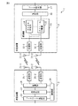
図1は、第1の実施形態による受信装置3を含む、通信システム1の概略構成図である。通信システム1は、2本のアンテナ21−1、21−2を有する送信装置2と、2本のアンテナ31−1、31−2を有する受信装置3とを有する。そして送信装置2は、各アンテナ21−1、21−2から同時に無線信号である送信信号を放射する。一方、受信装置3は、送信装置2から送信された送信信号を各アンテナ31−1、31−2を介して受信する。なお、それぞれのアンテナ31−1、31−2で受信された信号を、以下では受信信号と呼ぶ。受信装置3は、各受信信号に基づいて送信信号を求める。
なお、この実施形態において、送信装置2が有するアンテナの数は単なる例示にすぎず、送信装置2が有するアンテナの数は、送信装置2に対して物理的に実装可能な2以上の任意の数に設定することができる。同様に、受信装置3が有するアンテナの数は単なる例示にすぎず、受信装置3が有するアンテナの数は、受信装置3に対して物理的に実装可能な2以上の任意の数に設定することができる。さらに、送信装置2が有するアンテナの数は、受信装置3が有するアンテナの数と異なっていてもよい。
FIG. 1 is a schematic configuration diagram of a
In this embodiment, the number of antennas included in the
送信装置2は、二つのアンテナ21−1、21−2と、コードワード生成部22と、符号化部23と、変調部24と、二つの送信部25−1、25−2と、制御部26とを有する。コードワード生成部22、符号化部23、変調部24、送信部25−1、25−2及び制御部26は、それぞれ別個の回路として送信装置2に実装されてもよく、それら回路が集積された一つの集積回路として、送信装置2に実装されてもよい。
The
コードワード生成部22は、送信されるデータを、制御部26により決定された、トランスポートサイズブロック(Transport Block Size、TBS)の長さを持つコードワードに分割する。なお、コードワードは、例えば、メディアアクセス制御(Media Access Control、MAC)層及びプロトコルデータユニット(Protocol Data Unit、PDU)層の規定にしたがった、MAC-PDUデータとすることができる。またコードワード生成部22は、制御部26により決定された、符号化部23により符号化されるコードワードに対するストリーム数を参照して、生成したコードワードを符号化部23に割り当てる。なおストリーム数は、一つのコードワードに対して同時に送信されるデータ数を表す。
コードワード生成部22は、生成したコードワードを符号化部23へ渡す。
The
The
符号化部23は、コードワード生成部22から受け取ったコードワードに対して、畳込み符号化処理あるいはターボ符号化処理などの誤り訂正用符号化処理を実行する。さらに符号化部23は、制御部26から取得したストリーム数で符号化されたコードワードを分割することにより、データストリームを生成する。そして符号化部23は、符号化されたコードワードをデータストリーム単位で変調部24へ出力する。
The
変調部24は、制御部26により決定された変調モードMODに従って、符号化部23から受け取ったデータストリームを直交変調する。
さらに、変調部24は、制御部26により決定されたプレコーディング行列に従って、各データストリームを送信部25−1及び25−2の何れかに出力する。
The
Further, the
送信部25−1、25−2は、それぞれ、変調部24から入力されたデータストリームを、無線周波数を持つ搬送波に重畳することにより送信信号を生成する。また送信部25−1、25−2は、ハイパワーアンプを有する。そして送信部25−1、25−2は、送信信号の強度を所望のレベルに増幅する。また、送信部25−1、25−2は、それぞれ、アンテナ21−1、21−2に接続されており、送信信号を接続されたアンテナを介して送信する。
Each of the transmission units 25-1 and 25-2 generates a transmission signal by superimposing the data stream input from the
制御部26は、送信装置2全体を制御する。そして制御部26は、例えば、受信装置3から受信したフィードバック情報を参照して、コードワードの長さ、変調モード、各コードワードのストリーム数及びプレコーディング行列を決定する。そして制御部26は、コードワードの長さ、変調モードなどの情報を、送信装置2の関連する各部へ通知する。
なお、フィードバック情報には、例えば、受信装置3において受信された信号の品質を表すCQI値などが含まれる。制御部26は、何れかのアンテナに接続された受信部(図示せず)から受け取った、受信装置3からの信号を復調及び復号し、その復号された信号からフィードバック情報を抽出できる。
The
Note that the feedback information includes, for example, a CQI value representing the quality of a signal received by the receiving
次に、第1の実施形態による受信装置3について説明する。受信装置3は、二つのアンテナ31−1、31−2と、二つの受信部32−1、32−2と、復調部33と、復号部36と、データ統合部37とを有する。受信部32−1、32−2、復調部33、復号部36及びデータ統合部37は、別個の回路として受信装置3に実装されてもよく、それら回路が集積された一つの集積回路として、受信装置3に実装されてもよい。
Next, the receiving
受信部32−1、32−2は、それぞれ、アンテナ31−1、31−2と接続されている。そして受信部32−1、32−2は、それぞれ、アンテナ31−1、31−2を介して、送信装置2の各アンテナ21−1、21−2から送信された送信信号を受信する。
また受信部32−1、32−2は、それぞれ、低ノイズアンプを有し、その低ノイズアンプにより、受信信号を増幅する。そして受信部32−1、32−2は、増幅した受信信号に中間周波数を持つ信号を重畳して受信信号の周波数をベースバンド周波数に変換した後、その受信信号を復調部33へ出力する。
The receiving units 32-1 and 32-2 are connected to the antennas 31-1 and 31-2, respectively. The receiving units 32-1 and 32-2 receive the transmission signals transmitted from the antennas 21-1 and 21-2 of the
Each of the reception units 32-1 and 32-2 has a low noise amplifier, and amplifies the reception signal by the low noise amplifier. Then, receiving sections 32-1 and 32-2 superimpose a signal having an intermediate frequency on the amplified received signal and convert the frequency of the received signal to a baseband frequency, and then output the received signal to
復調部33は、受信部32−1、32−2から受け取った受信信号から送信装置2の各アンテナから送信された送信信号を分離する。そのために、復調部33は、チャネル推定部34とストリーム分離部35とを有する。
チャネル推定部34は、送信信号と受信信号の関係を表すチャネル行列を求める。例えば、チャネル推定部34は、送信装置2の各アンテナから送信された信号に含まれるパイロット信号のような、送信装置2及び受信装置3が既知である信号のチャネルインパルス応答値を求める。そしてチャネル推定部34は、そのチャネルインパルス応答値をチャネル行列の各要素とする。この場合、送信信号と受信信号の関係は、チャネル行列を用いて次式で表される。
チャネル推定部34は、チャネル行列をストリーム分離部35に渡す。
ストリーム分離部35は、チャネル行列に基づいて、受信信号から送信信号を分離する。なお、ストリーム分離部35の詳細については後述する。
The
The
The
The
復調部33は、分離した送信信号を、その送信信号に対して適用された変調方式に従って復調し、その復調された信号を復号部36に渡す。
また復調部33は、送信装置2へフィードバックするためのCQI値などのフィードバック情報を算出し、そのフィードバック情報を図示しない送信部へ送る。送信部は、フィードバック情報を持つ信号を直交変調した後、無線周波数を持つ搬送波に重畳することにより無線信号を生成する。そして送信部は、フィードバック情報が搬送される無線信号を何れかのアンテナを介して放射する。
The
The
復号部36は、復調部33から受け取ったデータストリームを結合することにより、符号化されたコードワードを生成する。そして復号部36は、その符号化されたコードワードに対して誤り訂正復号処理を実行する。復号部36は、復号処理がなされたコードワードをデータ統合部37へ出力する。
The
データ統合部37は、復号部36から受け取ったコードワードを結合し、元のデータに戻す。そしてデータ統合部37は、その元のデータを、受信装置3の他の構成要素へ出力する。
The
以下、ストリーム分離部35の詳細について説明する。
図2は、ストリーム分離部35の概略構成図である。ストリーム分離部35は、チャネル入替部41と、QR分解部42と、候補グループ設定部43と、共通グループ検索部44と、メトリック計算部45と、最小値検索部46と、追加メトリック計算部47と、対数尤度比算出部48とを有する。
ストリーム分離部35が有するこれらの各部は、それぞれ別個の演算回路であってもよい。あるいは、ストリーム分離部35が有するこれらの各部は、その各部の機能を実現する一つの演算回路であってもよい。
Details of the
FIG. 2 is a schematic configuration diagram of the
Each of these units included in the
チャネル入替部41は、チャネル行列Hの列を入れ替えることにより、変換チャネル行列H'を作成する。変換チャネル行列H'を用いた送信信号と受信信号の関係は、次式により表される。
QR分解部42は、第1QR分解部421と第2QR分解部422とを有する。
第1QR分解部421は、チャネル推定部35から受け取ったチャネル行列Hをユニタリ行列Qと上三角行列RにQR分解する。チャネル行列Hは、ユニタリ行列Qと上三角行列Rを用いて次式のように表される。
The first
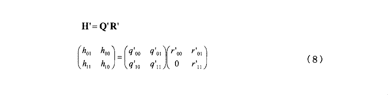
また第2QR分解部422は、チャネル入替部41から受け取った変換チャネル行列H'をユニタリ行列Q'と上三角行列R'にQR分解する。チャネル行列H'は、ユニタリ行列Q'と上三角行列R'を用いて次式のように表される。
なお、第1QR分解部421及び第2QR分解部422は、QR分解を行うために、例えば、ギブンス回転、ハウスホルダー変換あるいはグラム・シュミット分解などを用いることができる。
QR分解部42は、ユニタリ変換ベクトルz、z'及び上三角行列R、R'を候補グループ設定部43へ渡す。
The second
Note that the first
The
候補グループ設定部43は、第1候補グループ設定部431と第2候補グループ設定部432とを有する。
第1候補グループ設定部431は、チャネル行列Hに基づいて算出されたユニタリ変換ベクトルz及び上三角行列Rを用いて、送信信号の候補の組を求める。ここで(7)式を参照すると、ユニタリ変換信号z0は、送信信号x0及び送信信号x1の両方の成分を含んでいる。そこで、第1候補グループ設定部431は、(7)式における、ユニタリ変換信号z0に関する式に基づいて、ユニタリ変換信号z0から送信信号x1の候補に関する成分をキャンセルすることにより算出した残留成分を、送信信号x0の推定値として求める。そして第1候補グループ設定部431は、送信信号x1がある候補c1iである場合の送信信号x0の推定値に最も近い送信信号x0が取り得る値と、送信信号x1のその候補との組を、送信信号の候補の組とする。
The candidate
The first candidate
送信信号x1が、c1i(i=0,1,...,m1-1)であれば、送信信号x0の推定値u0iは次式により表される。c1iは、シンボルレプリカであり、送信信号x1に対して適用された変調方式において送信信号x1が取り得る信号値を受信装置3が発生させたものである。c1iは、実数(I)信号と虚数(Q)信号のセットによって表される。m1は、送信信号x1に対して適用された変調方式が取り得る値の数である。例えば、変調方式が16QAMであれば、m1=16であり、また変調方式が64QAMであれば、m1=64である。
第1候補グループ設定部431は、推定値u0iに最も近い送信信号x0の候補を決定するために、例えば、推定値u0iが属する象限を判定する。
図3(a)〜図3(c)を参照しつつ、象限判定処理について説明する。なお、一例として、送信信号x0に適用される変調方式は64QAMである。そして図3(a)〜図3(c)のそれぞれにおいて、横軸はI信号成分を表し、縦軸はQ信号成分を表す。また各点301は、それぞれ、送信信号x0が取り得る信号値に対応する信号点である。例えば、点301aはシンボル"101111"に対応する信号値を表す。また星印310は、(10)式にシンボルレプリカc1iを入力することにより得られた推定値u0iを表す。この例では、推定値u0iのI信号成分及びQ信号成分の何れも負の値である。
The first candidate
The quadrant determination process will be described with reference to FIGS. 3 (a) to 3 (c). As an example, the modulation scheme applied to the transmitted signal x 0 is 64QAM. In each of FIGS. 3A to 3C, the horizontal axis represents the I signal component and the vertical axis represents the Q signal component. The
図3(a)に示されるように、推定値u0iは、I信号成分及びQ信号成分の何れも負であるため、第4象限320に位置している。そのため、第1候補グループ設定部431は、送信信号x0が第4象限内に属する信号値の何れかであると推定する。
次に、第1候補グループ設定部431は、推定値u0iが属する第4象限の中心に相当する信号値(-4/√42, -4/√42)を原点O'としたときに、推定値u0iが属する象限を判定する。すなわち、第1候補グループ設定部431は、推定値u0iから第4象限の中心に相当する信号値(-4/√42, -4/√42)を減算することにより推定値u'0iを求め、その推定値u'0iのI信号成分及びQ信号成分がそれぞれ正か負かを判定する。図3(b)に示されるように、この例では、推定値u0iは、原点O'を基準とした第1象限330に属している。そのため、第1候補グループ設定部431は、送信信号x0が原点O'を基準とした第1象限330内に属する信号値の何れかであると推定する。
As shown in FIG. 3A, the estimated value u 0i is located in the
Next, when the first candidate
第1候補グループ設定部431は、推定値u0iに最も近い信号値が求まるまで、上記の象限判定処理を繰り返す。この例では、第1候補グループ設定部431は、推定値u0iが属する、原点O'を基準とした第1象限330の中心に相当する信号値(-2/√42, -2/√42)を原点O"としたときに、推定値u0iが属する象限を判定する。すなわち、第1候補グループ設定部431は、推定値u0iから第1象限330の中心に相当する信号値(-2/√42, -2/√42)を減算することにより推定値u"0iを求め、その推定値u"0iのI信号成分及びQ信号成分がそれぞれ正か負かを判定する。そして図3(c)に示されるように、推定値u0iは、原点O"を基準とした第2象限340に属している。その第2象限340は、1個のシンボル"110001"に対応する。そのため、シンボル"110001"に相当する信号値が推定値u0iに最も近い。
そこで、第1候補グループ設定部431は、送信信号x1がc1iであれば、送信信号x0の候補をシンボル"110001"に対応する信号値に設定する。なお、以下では、上記のようにして設定された、送信信号x1がc1iであるときの送信信号x0の候補をx0 (min)(c1i)と表す。
このように、第1候補グループ設定部431は、象限判定を用いることにより、乗算のような演算量の多い処理の実行回数を減らせるので、x0 (min)(c1i)を特定するための演算量を削減できる。
The first candidate
Therefore, if transmission signal x 1 is c 1i , first candidate
As described above, the first candidate
なお、(10)式に従って推定値u0iが算出される場合、(z0-r01c1i)をr00で除算する演算が行われる。そこで、第1候補グループ設定部431は、推定値u0iを(10)式の右辺の分子の項(z0-r01c1i)として算出するとともに、2回目以降の象限判定における原点を、推定値u0iが属すると判定された象限の中心に相当する信号値にr00を乗じた値としてもよい。これにより、除算処理の実行回数が減るので、第1候補グループ設定部431は、x0 (min)(c1i)を決定するための演算量を減らすことができる。
When the estimated value u 0i is calculated according to the equation (10), an operation for dividing (z 0 -r 01 c 1i ) by r 00 is performed. Therefore, the first candidate
第1候補グループ設定部431は、各シンボルレプリカc1i(i=0,1,...,m1-1)について上記の処理を行うことにより、送信信号x0の候補とx1の候補の組の集合である、第1候補グループφ1を求める。ただし、第1候補グループφ1は以下のように表される。
φ1={(x0 (min)(c10), c10), (x0 (min)(c11), c11),..., (x0 (min)(c1m1-1), c1m1-1)}
第1候補グループφ1には、送信信号x1に対して適用された変調方式が取り得る値の数m1と等しい数の候補が含まれる。
The first candidate
φ 1 = {(x 0 (min) (c 10 ), c 10 ), (x 0 (min) (c 11 ), c 11 ), ..., (x 0 (min) (c 1m1-1 ) , c 1m1-1 )}
The first candidate group φ 1 includes a number of candidates equal to the number m 1 of values that the modulation scheme applied to the transmission signal x 1 can take.
第2候補グループ設定部432は、第1候補グループ設定部431と同様に、変換チャネル行列H'に基づいて算出されたユニタリ変換ベクトルz'及び上三角行列R'を用いて、送信された可能性が有る送信信号の組の候補を求める。ここで(9)式を参照すると、ユニタリ変換ベクトルの要素z'0は、送信信号x0及び送信信号x1の両方の成分を有している。そこで、第2候補グループ設定部432は、(9)式における、ユニタリ変換信号z'0から送信信号x0の成分をキャンセルすることにより算出した残留成分を、送信信号x1の推定値として求める。そして第2候補グループ設定部432は、送信信号x0がある候補c0iである場合の送信信号x1の推定値に最も近い送信信号x1が取り得る値と、送信信号x0のその候補との組を、送信信号の候補の組とする。
Similarly to the first candidate
送信信号x0が、シンボルレプリカc0i(i=0,1,...,m0-1)であれば、送信信号x1の推定値u1iは次式により表される。c0iは送信信号x0のシンボルレプリカである。m0は送信信号x0に対して適用された変調方式が取り得る値の数である。
第2候補グループ設定部432は、第1候補グループ設定部431と同様に、推定値u1iが属する象限の判定を繰り返すことにより、推定値u1iに最も近いシンボルの信号値を、送信信号x0がc0iである場合の送信信号x1の候補として決定する。なお、以下では、送信信号x0がc0iであるときの送信信号x1の候補をx1 (min)(c0i)と表す。そして第2候補グループ設定部432は、各シンボルレプリカc0i(i=0,1,...,m0-1)について送信信号x1の候補を求めることにより、送信信号x0の候補とx1の候補の組の集合である、第2候補グループφ2を求める。ただし、第2候補グループφ2は以下のように表される。
φ2={(c00, x1 (min)(c00)), (c01, x1 (min)(c01)),..., (c0m0-1, x1 (min)(c0m0-1))}
候補グループ設定部43は、第1候補グループφ1及び第2候補グループφ2を共通グループ検索部44及び追加メトリック計算部47へ渡す。
Similar to the first candidate
φ 2 = {(c 00 , x 1 (min) (c 00 )), (c 01 , x 1 (min) (c 01 )), ..., (c 0m0-1 , x 1 (min) ( c 0m0-1 ))}
The candidate
共通グループ検索部44は、第1候補グループφ1と第2候補グループφ2とで共通する送信信号x0の候補とx1の候補の組を検索する。第1候補グループφ1と第2候補グループφ2は、同一のチャネル行列に基づく異なる関係式に従って得られた送信信号x0の候補とx1の候補の組の集合である。そのため、実際に送信された送信信号の組は、両方の候補グループに含まれる可能性が高い。そこで共通グループ検索部44は、二つの候補グループにおいて共通する送信信号の候補の組の集合を、メトリック計算の対象となる共通グループとする。
The common
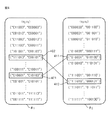
図4は、第1候補グループφ1及び第2候補グループφ2と、その二つのグループに共通する送信信号x0の候補とx1の候補の組を示す概念図である。なお、図4では、一例として、送信信号x0とx1はともに64QAMにより変調された信号である。
図4において、第1候補グループφ1及び第2候補グループφ2には、それぞれ、m個の送信信号の候補の組が含まれている。
このうち、第1候補グループφ1における組401と、第2候補グループφ2における組411は、何れも送信信号x0として"010001"、送信信号x1として"010100"を含んでいる。そのため、共通グループ検索部44は、("010001", "010100")を送信信号(x0,x1)に対する送信信号候補の組として選択する。また、第1候補グループφ1における組402と、第2候補グループφ2における組412は、何れも送信信号x0として"111010"、送信信号x1として"000101"を含んでいる。そのため、共通グループ検索部44は、("111010", "000101")も送信信号(x0,x1)に対する送信信号候補の組として選択する。
共通グループ検索部44は、共通グループをメトリック計算部45へ渡す。
FIG. 4 is a conceptual diagram showing a first candidate group φ 1 and a second candidate group φ 2 and a set of transmission signal x 0 candidates and x 1 candidates common to the two groups. In FIG. 4, as an example, the transmission signal x 0 and x 1 are both modulated signals by 64QAM.
In FIG. 4, each of the first candidate group φ 1 and the second candidate group φ 2 includes a set of m transmission signal candidates.
Among these, the
The common
共通グループに含まれる送信信号候補の組の数は、チャネル変動またはノイズによって変動し、最小の場合1となり、最大の場合、min(m0,m1)となる。なお、m0、m1は、それぞれ、送信信号x0、x1に対して適用される変調方式において送信信号x0、x1が取り得る値の数である。また関数min(a,b)は、aとbのうちの小さい方の値を出力する関数である。ここで、推定値u0iに着目すると、上記の(10)式は、以下のように書き換えられる。
メトリック計算部45は、共通グループに含まれる送信信号候補の組ごとに、実際に送信された送信信号である確からしさの指標となるメトリックを計算する。このメトリックは、着目する送信信号候補の組が実際に送信された送信信号であるとした場合の推定受信信号と、実際の受信信号との距離を表す。例えば、メトリック計算部45は、メトリックdjとして、次式のように、ユニタリ変換信号z0、z1と、送信信号候補の組(c0j,c1j)(j=0,1,...,k-1)を(7)式の右辺の第1項に入力することにより得られた推定受信信号との2乗ユークリッド距離の和を算出する。
あるいは、メトリック計算部45は、メトリックdjとして、次式のように、ユニタリ変換信号z0、z1と、送信信号候補の組(c0j,c1j)を(7)式の右辺の第1項に入力することにより得られた推定受信信号とのマンハッタン距離を算出してもよい。
メトリック計算部45は、共通グループに含まれる各送信信号候補の組及び対応するメトリックdjを最小値検索部46へ渡す。
The
Alternatively, the
The
最小値検索部46は、送信信号推定部の一例であり、各送信信号候補のメトリックdjのうちの最小値を求める。そして最小値検索部46は、メトリックdjのうちの最小値dminに対応する送信信号候補の組(c0min,c1min)が、実際に送信された送信信号の組(x0,x1)であると推定する。以下では、実際に送信された送信信号の組(x0,x1)であると推定された送信信号候補の組(c0min,c1min)を最尤シンボルセットと呼び、最尤シンボルセットに含まれる送信信号候補であるシンボルレプリカに対応するシンボル(x0 (ML),x1 (ML))を最尤シンボルと呼ぶ。
最小値検索部46は、最小値dmin及び最尤シンボルセット(c0min,c1min)を対数尤度比算出部48へ渡す。また最小値検索部46は、共通グループに含まれる各送信信号候補の組及び各組について算出したメトリックdjを追加メトリック計算部47へ渡す。
The minimum
The minimum
追加メトリック計算部47は、最尤シンボルのそれぞれについて、何れかのビットの値を反転させたシンボルの中で最尤シンボルから所定の距離内に位置するシンボルを反転ビットシンボルとして特定する。そして追加メトリック計算部47は、送信信号x0について求めた反転ビットシンボルs0p(p=1,2,...,m)に対応するシンボルレプリカx0pについて、そのシンボルレプリカx0pに対応する送信信号x1のシンボルレプリカx1 (min)(x0p)を特定する。例えば、追加メトリック計算部47は、第2候補グループφ2に含まれる送信信号候補の組の中から、シンボルレプリカx0pを含む組を検出する。そして追加メトリック計算部47は、検出した送信信号候補の組に基づいて、シンボルレプリカx0pに対応する送信信号x1のシンボルレプリカx1 (min)(x0p)を特定する。同様に、追加メトリック計算部47は、送信信号x1について求めた反転ビットシンボルs1pに対応するシンボルレプリカx1pについて、第1候補グループφ1を参照することで、そのシンボルレプリカx1pに対応する送信信号x0のシンボルレプリカx0 (min)(x1p)を特定する。
For each maximum likelihood symbol, the additional
追加メトリック計算部47は、送信信号x0についての反転ビットシンボルs0rに関連するシンボルレプリカの組(x0p, x1 (min)(x0p))とユニタリ変換信号z0、z1との追加メトリックd(additional)を求める。同様に、追加メトリック計算部47は、送信信号x1についての反転ビットシンボルs1rに関連するシンボルレプリカの組(x0 (min)(x1p), x1p)とユニタリ変換信号z0、z1との追加メトリックd(additional)を求める。例えば、追加メトリック計算部47は、(13)式または(14)式に従ってこれらの追加メトリックを算出できる。追加メトリックは、復号部36が誤り訂正復号処理を実行するために使用する対数尤度比を算出するために使用される。
そのため、追加メトリック計算部47は、各反転ビットシンボルについて求めた追加メトリックを対数尤度比算出部48へ出力する。
なお、シンボルレプリカの組(x0 (min)(x1p), x1p)及び(x0p, x1 (min)(x0p))のうち、メトリック計算部45によって既にメトリックdが計算されている組については、追加メトリック計算部47はそのメトリックdを対数尤度比算出部48へ出力する。
The additional
Therefore, the additional
Of the symbol replica pairs (x 0 (min) (x 1p ), x 1p ) and (x 0p , x 1 (min) (x 0p )), the
図5は、一例として、送信信号x0が64QAMにより変調されており、かつ送信信号x0に対応する最尤シンボルが"000000"である場合において、反転ビットごとに1番近いシンボルが反転ビットシンボルとして選択された場合の反転ビットシンボルを示す図である。図5に示されるように、ブロック501〜506に示されるシンボルが反転ビットシンボルとして選択される。例えば、反転ビットが右端のビットである場合、ブロック501に示されるシンボル"000001"が、ブロック500に示される最尤シンボルに最も近い。そこで反転ビットシンボルとして"000001"が選択される。また、反転ビットが左端のビットである場合、左端のビットが"1"であるシンボルのうちで最尤シンボルに最も近い、ブロック506に示されるシンボル"100010"が反転ビットシンボルとして選択される。
FIG. 5 shows, as an example, when the transmission signal x 0 is modulated by 64QAM and the maximum likelihood symbol corresponding to the transmission signal x 0 is “000000”, the nearest symbol for each inversion bit is the inversion bit. It is a figure which shows the inversion bit symbol at the time of being selected as a symbol. As shown in FIG. 5, the symbols shown in
図6は、送信信号x0に対応する最尤シンボルが"000000"である場合において、反転ビットごとに2番目に近いシンボルまでを反転ビットシンボルとして選択された場合の反転ビットシンボルを示す図である。図6に示されるように、ブロック601〜614に示されるシンボルが反転ビットシンボルとして選択される。
なお、各シンボルに対応する信号点の位置は予め決まっているので、最尤シンボルごとの反転ビットシンボルは予め決定することができる。そこで、最尤シンボルごとに対応する反転ビットシンボルを表す参照テーブルが、予め追加メトリック計算部47が有するメモリ回路に記憶されていてもよい。この場合、追加メトリック計算部47は、参照テーブルを参照することにより、最尤シンボルに対応する反転ビットシンボルを特定できる。
FIG. 6 is a diagram illustrating inverted bit symbols when the maximum likelihood symbol corresponding to the transmission signal x 0 is “000000” and the symbols closest to the second symbol are selected as inverted bit symbols for each inverted bit. is there. As shown in FIG. 6, the symbols shown in blocks 601-614 are selected as inverted bit symbols.
Since the position of the signal point corresponding to each symbol is determined in advance, the inverted bit symbol for each maximum likelihood symbol can be determined in advance. Therefore, a reference table representing inverted bit symbols corresponding to each maximum likelihood symbol may be stored in advance in a memory circuit included in the additional
対数尤度比算出部48は、ビットごとの対数尤度比(Log-likelihood ratio、LLR)を算出する。対数尤度比算出部48は、送信信号xrの左からn番目のビットに対するLLRであるビットLLRr(n)を次式に従って算出する。
また対数尤度比算出部48は、次式に従ってビットLLRr(n)を算出してもよい。
なお、復号部36により実行される誤り訂正復号処理が対数尤度比を用いない場合、追加メトリック計算部47及び対数尤度比算出部48は省略されてもよい。
The log-likelihood
Further, the log likelihood
When the error correction decoding process executed by the
図7及び図8は、送信信号分離処理の動作フローチャートである。この送信信号分離処理は、ストリーム分離部35によって制御され、そして受信装置3が受信信号を受信する度に繰り返し実行される。
QR分解部42の第1QR分解部421は、チャネル行列Hをユニタリ行列Qと上三角行列RにQR分解する(ステップS101)。そして第1QR分解部421は、受信信号ベクトルYにユニタリ行列Qのエルミート共役QHを乗じて受信信号ベクトルYのユニタリ変換ベクトルz(=(z0,z1))を生成する(ステップS102)。第1QR分解部421は、ユニタリ変換ベクトルZ及び上三角行列Rを候補グループ設定部43へ出力する。
7 and 8 are operation flowcharts of the transmission signal separation process. This transmission signal separation process is controlled by the
The first
候補グループ設定部43の第1候補グループ設定部431は、着目する送信信号x0について、ユニタリ変換信号z0から他の送信信号x1のシンボルレプリカc1iによる成分をキャンセルした残留成分を、着目送信信号x0の推定値u0iとして算出する(ステップS103)。その際、第1候補グループ設定部431は、各シンボルレプリカc1i(i=0,1,2,...,m1-1)についてそれぞれ推定値u0iを算出する。そして第1候補グループ設定部431は、各推定値u0iに最も近いシンボルレプリカx0 (min)(c1i)と対応する送信信号x1のシンボルレプリカc1iとの組(x0 (min)(c1i), c1i)を一つの送信信号の候補の組とする第1候補グループを生成する(ステップS104)。第1候補グループ設定部431は、第1候補グループを共通グループ検索部44及び追加メトリック計算部47へ出力する。
The first candidate
チャネル入替部41は、チャネル行列Hの列を入れ替えることで変換チャネル行列H'を作成する(ステップS105)。そしてチャネル入替部41は、変換チャネル行列H'をQR分解部42へ出力する。
QR分解部42の第2QR分解部422は、変換チャネル行列H'をユニタリ行列Q'と上三角行列R'にQR分解する(ステップS106)。そして第2QR分解部422は、受信信号ベクトルYにユニタリ行列Q'のエルミート共役Q'Hを乗じて受信信号ベクトルYのユニタリ変換ベクトルz'(=(z'0,z'1))を生成する(ステップS107)。第2QR分解部422は、ユニタリ変換ベクトルz'及び上三角行列R'を候補グループ設定部43へ出力する。
The
The second
候補グループ設定部43の第2候補グループ設定部432は、着目する送信信号x1について、ユニタリ変換信号z'0から他の送信信号x0のシンボルレプリカc0iによる成分をキャンセルした残留成分を着目送信信号x1の推定値u1iとして算出する(ステップS108)。その際、第2候補グループ設定部432は、各シンボルレプリカc0i(i=0,1,2,...,m0-1)についてそれぞれ推定値u1iを算出する。そして第2候補グループ設定部432は、各推定値u1iに最も近いシンボルレプリカx1 (min)(c0i)と、対応する送信信号x0のシンボルレプリカc0iとの組(c0i, x1 (min)(c0i))を一つの送信信号の候補の組とする第2候補グループを生成する(ステップS109)。第2候補グループ設定部432は、第2候補グループを共通グループ検索部44及び追加メトリック計算部47へ出力する。
共通グループ検索部44は、第1候補グループと第2候補グループ間で共通する送信信号の候補の組を検索する(ステップS110)。そして共通グループ検索部44は、その共通する送信信号の候補の組を含む共通グループをメトリック計算部45へ出力する。
The second candidate
The common
図8に示されるように、メトリック計算部45は、共通グループに含まれる送信信号の候補の各組について、その送信信号候補の組に基づく推定受信信号の組と受信信号の組との距離の指標を表すメトリックを算出する(ステップS111)。
最小値検索部46は、メトリックの最小値に対応する組に含まれる送信信号の候補を実際に送信された送信信号と推定する(ステップS112)。最小値検索部46は、メトリックの最小値及び推定された送信信号を対数尤度比算出部48へ出力する。また最小値検索部46は、推定された送信信号を追加メトリック計算部47へ出力する。
As shown in FIG. 8, the
The minimum
追加メトリック計算部47は、最尤シンボルに対して反転ビットを持つシンボルのうち所定距離内のシンボルを反転ビットシンボルとして選択する(ステップS113)。そして追加メトリック計算部47は、第1及び第2候補グループを参照して反転ビットシンボルに対応するシンボルレプリカの組を決定する(ステップS114)。追加メトリック計算部47は、反転ビットシンボルに対応するメトリックを算出する(ステップS115)。追加メトリック計算部47は、メトリック及び反転ビットシンボルを対数尤度比算出部48へ出力する。
対数尤度比算出部48は、各最尤シンボルの反転ビットのそれぞれについて、最小メトリックの2乗根と反転ビットシンボルに対応するメトリックの最小値の2乗根の差を対数尤度比として算出する(ステップS116)。そして対数尤度比算出部48は、推定された送信信号と、対数尤度比及びその対数尤度比の算出に用いられた反転ビットシンボルを復号部36へ出力する。
その後、ストリーム分離部35は、送信信号分離処理を終了する。
なお、ストリーム分離部35は、ステップS101〜S104の処理と、ステップS105〜S109の処理を並列に実行してもよい。
The additional
The log likelihood
Thereafter, the
The
表1は、二つの送信信号がともに64QAMにより変調されている場合における、本実施形態による送信信号分離処理により行われるメトリック計算回数と、従来技術による送信信号分離処理により行われるメトリック計算回数を表す。表1では、メトリックは(13)式に従って二乗ユークリッド距離により算出され、1回のノルムの計算が1回のメトリックの計算であるとした。追加メトリック計算部47は、それぞれの反転ビットについて、その反転ビットを含むシンボルのうち、最尤シンボルと最も近いシンボルのみを反転ビットシンボルとしてメトリックを計算するものとした。
一方、第1候補グループと第2候補グループ間で共通する送信信号の候補の組が64個存在する場合、すなわち、両候補グループが等しい場合、メトリック計算回数は最大となる。この場合、共通する組について128(=2×64)回のメトリックが計算される。ただし、反転ビットシンボルを含む送信信号の組は共通グループに含まれるので、反転ビットシンボルに関するメトリック計算回数は0となる。
表1に示されるように、メトリック計算回数が最大となる場合でも、本実施形態による方式によるメトリック計算回数は、他の従来方式による送信信号分離方式によるメトリック計算回数よりも少ない。
Table 1 shows the number of metric calculations performed by the transmission signal separation process according to the present embodiment and the number of metric calculations performed by the transmission signal separation process according to the conventional technique when both of the two transmission signals are modulated by 64QAM. . In Table 1, the metric is calculated by the square Euclidean distance according to the equation (13), and one norm calculation is a single metric calculation. For each inverted bit, the additional
On the other hand, when there are 64 sets of transmission signal candidates common between the first candidate group and the second candidate group, that is, when both candidate groups are equal, the number of metric calculations is maximized. In this case, 128 (= 2 × 64) metrics are calculated for the common set. However, since the set of transmission signals including inverted bit symbols is included in the common group, the metric calculation count for the inverted bit symbols is zero.
As shown in Table 1, even when the number of metric calculations is maximized, the number of metric calculations by the method according to the present embodiment is smaller than the number of metric calculations by the transmission signal separation method by other conventional methods.
以上に説明してきたように、第1の実施形態による受信装置は、送信信号を分離する際、チャネルの順序を入れ替えた二つのチャネル行列を求める。そしてこの受信装置は、チャネル行列ごとに送信信号の候補の組を求める。その際、この受信装置は、着目する送信信号について、全ての送信信号に関する成分を持つ受信信号のユニタリ変換信号から、他の送信信号の候補に相当する成分をキャンセルした残留成分に最も近いシンボルレプリカをその着目する送信信号の候補とする。そしてこの受信装置は、チャネル行列ごとに求めた送信信号の候補の組の二つの集合において共通する組についてのみメトリックを計算することで、送信信号を推定する。このように、この受信装置は、演算量の多いメトリックを計算せずに送信信号の候補の組を決定できるので、メトリックの計算回数を減らすことができる。その結果、この受信装置は、送信信号を分離する際の演算量を削減できる。 As described above, the receiving apparatus according to the first embodiment obtains two channel matrices in which the order of channels is changed when separating transmission signals. The receiving apparatus obtains a set of transmission signal candidates for each channel matrix. In this case, the receiving apparatus, for the transmission signal of interest, is the symbol replica closest to the residual component obtained by canceling the component corresponding to another transmission signal candidate from the unitary conversion signal of the reception signal having components related to all transmission signals. Is a candidate for the target transmission signal. The receiving apparatus estimates a transmission signal by calculating a metric only for a pair common to two sets of transmission signal candidate sets obtained for each channel matrix. In this way, this receiving apparatus can determine a set of transmission signal candidates without calculating a metric with a large amount of calculation, and thus the number of metric calculations can be reduced. As a result, this receiving apparatus can reduce the amount of calculation when the transmission signal is separated.
次に、第2の実施形態による受信装置について説明する。
第2の実施形態による受信装置は、送信信号分離処理を行う際、第1の候補グループと第2の候補グループ間で共通する送信信号の候補の組に優先順位を付け、優先順位が高い組についてのみメトリックを計算する。この第2の実施形態による受信装置は、第1の実施形態による受信装置と比較して、ストリーム分離部のみが異なる。そこで以下では、ストリーム分離部について説明する。
Next, a receiving apparatus according to the second embodiment will be described.
When performing a transmission signal separation process, the receiving apparatus according to the second embodiment assigns a priority to a set of transmission signal candidates common to the first candidate group and the second candidate group, and sets a higher priority. Calculate metrics only for. The receiving apparatus according to the second embodiment differs from the receiving apparatus according to the first embodiment only in the stream separation unit. Therefore, hereinafter, the stream separation unit will be described.
図9は、第2の実施形態による受信装置のストリーム分離部351の概略構成図である。ストリーム分離部351は、チャネル入替部41と、QR分解部42と、候補グループ設定部43と、共通グループ検索部44と、メトリック計算部45と、最小値検索部46と、追加メトリック計算部47と、対数尤度比算出部48と、ランキング決定部51とを有する。
ストリーム分離部351が有するこれらの各部は、それぞれ別個の演算回路であってもよい。あるいは、ストリーム分離部351が有するこれらの各部は、その各部の機能を実現する一つの演算回路であってもよい。
なお、図9において、ストリーム分離部351の各部には、図2に示された第1の実施形態によるストリーム分離部35の対応する構成要素の参照番号と同じ参照番号を付した。ストリーム分離部351は、ランキング決定部51を有する点で、第1の実施形態によるストリーム分離部35と異なる。
FIG. 9 is a schematic configuration diagram of the
Each of these units included in the
In FIG. 9, the same reference numerals as those of the corresponding components of the
ランキング決定部51は、第1信号ランキング決定部511と、第2信号ランキング決定部512とを有する。
第1信号ランキング決定部511は、第1候補グループに含まれる各送信信号候補の組に優先順位をつけるためのランキング値を算出する。ここで、ユニタリ変換ベクトルzと上三角行列R及び送信信号ベクトルXとの関係を表す(7)式に示されるように、送信信号x1は、ユニタリ変換信号z1を用いて次式のように表される。
そこで第1信号ランキング決定部511は、送信信号x1が取り得る信号値に対応するシンボルレプリカc1iのそれぞれに対して推定値v1に近い順に従ってランキング値を決定する。そして第1信号ランキング決定部511は、例えば、推定値v1に近い信号値ほど小さいランキング値を設定する。このランキング値は、各信号値が送信信号x1である確からしさを表す。この例では、ランキング値が小さいほど、その確からしさは高い。
ランキング値を決定するために、第1信号ランキング決定部511は、送信信号x1が取り得る信号値を表すI信号とQ信号の座標系において、送信信号x1の推定値v1(=z1/r11)が属する象限を判定する。そして第1信号ランキング決定部511は、推定値v1が属する象限の中心位置を原点として、((1/2)log2m1)回の象限判定を行うことにより、各信号値に対して推定値v1に近い順序を決定する。なお、m1は、送信信号x1に対して適用される変調方式が取り得る値の数であり、例えば、変調方式がQPSKであれば、m1=2である。
The
The first signal ranking
Therefore, the first signal ranking
In order to determine the ranking value, the first signal ranking
図10(a)及び図10(b)は、それぞれ、送信信号x1の推定値v1と送信信号x1が取り得る信号値との位置関係の例を示す図である。なお、一例として、送信信号x1に適用される変調方式はQPSKである。そして図10(a)及び図10(b)において、横軸はI信号成分を表し、縦軸はQ信号成分を表す。また各点1001a〜1001dは、それぞれ、送信信号x1が取り得る信号値に対応する。例えば、点1001aはシンボル"00"に対応する信号値を表す。また点1010は、推定値v1を表す。この例では、推定値v1のI信号成分及びQ信号成分の何れも正の値を持つ。したがって、4個の信号値のうち、シンボル"00"に対応する信号値が推定値v1に最も近い。一方、シンボル"11"に対応する信号値は、I成分とQ成分の両方とも推定値v1と異なるので、その信号値は推定値v1から最も遠い。そこで、第1信号ランキング決定部511は、例えば、シンボル"00"に対応するシンボルレプリカに対してランキング値"1"を設定し、一方、シンボル"11"に対応するシンボルレプリカに対してランキング値"4"を設定する。また、シンボル"01"に対応するシンボルレプリカ及びシンボル"00"に対応する信号値については、1回の象限判定では、どちらの信号値が推定値v1により近いか分からない。そのため、第1信号ランキング決定部511は、シンボル"01"に対応するシンボルレプリカ及びシンボル"00"に対応するシンボルレプリカに対して、それぞれ、ランキング値"2"を設定する。
FIG. 10 (a) and FIG. 10 (b), respectively, a diagram showing an example of the positional relationship between the estimated values v 1 and the signal value to obtain the transmission signal x 1 is taken by the transmitted signal x 1. As an example, the modulation scheme applied to the transmission signal x 1 is QPSK. In FIGS. 10A and 10B, the horizontal axis represents the I signal component, and the vertical axis represents the Q signal component. The
さらに、第1信号ランキング決定部511は、((1/2)log2m1)回よりも多くの象限判定を行ってもよい。これにより、第1信号ランキング決定部511は、全ての信号値について、推定値v1に近い順序を決定できる。
例えば、図10(b)に示されるように、推定値v1に対して2回目の象限判定処理を行うことにより、推定値v1が16個の領域のうちの領域1020に属していることが分かる。そして領域1020は、シンボル"10"に対応する信号値よりもシンボル"01"に対応する信号値に近い。そのため、第1信号ランキング決定部511は、シンボル"01"に対応する信号値の方がシンボル"10"に対応する信号値よりも推定値v1に近いと判定できる。そこで第1信号ランキング決定部511は、各シンボル"00"、"01"、"10"、"11"に対応するシンボルレプリカに対して、それぞれ、ランキング値"1"、"2"、"3"、"4"を設定する。
Further, the first signal ranking
For example, as shown in FIG. 10B, the estimated value v 1 belongs to the
第2信号ランキング決定部512は、第2候補グループに含まれる各送信信号候補の組に順位をつけるためのランキング値を算出する。そこで、第2信号ランキング決定部512は、第1信号ランキング決定部511と同様に、(9)式に基づいて、(z'1/r'11)を送信信号x0の推定値v0として算出する。そして第2信号ランキング決定部512は、推定値v0が属する象限を判定することにより、送信信号x0が取り得る信号値に対応する各シンボルレプリカc0iに対して推定値v0に近い順に従ってランキング値を決定する。
ランキング決定部51は、送信信号x0が取り得る信号値に対応する各シンボルレプリカc0iに設定されたランキング値R0i及び送信信号x1が取り得る信号値に対応する各シンボルレプリカc1iに設定されたランキング値R1iを候補グループ設定部43へ渡す。
The second signal ranking determining unit 512 calculates a ranking value for ranking each set of transmission signal candidates included in the second candidate group. Therefore, the second signal ranking determination unit 512, like the first signal ranking
The
候補グループ設定部43は、第1の実施形態における候補グループ設定部43と同様に、送信信号x0、x1の候補の組の集合である第1候補グループ及び第2候補グループを求める。
その際、第1候補グループ設定部431は、第1候補グループに含まれるそれぞれの送信信号候補の組に含まれるシンボルレプリカc1iに設定されたランキング値R1iを、その組が実際に送信された送信信号である確からしさを表すランキング値とする。同様に、第2候補グループ設定部432は、第2候補グループに含まれるそれぞれの送信信号候補の組に含まれるシンボルレプリカc0iに設定されたランキング値R0iを、その組が実際に送信された送信信号である確からしさを表すランキング値とする。
候補グループ設定部43は、第1候補グループ、第2候補グループ及びそれら候補グループに含まれるそれぞれの組のランキング値を共通グループ検索部44及び追加メトリック計算部47へ出力する。
Similar to the candidate
At that time, the first candidate
The candidate
共通グループ検索部44は、第1候補グループと第2候補グループ間で共通する送信信号候補の組を検索し、その共通する送信信号候補の組の集合を共通グループとする。そして共通グループ検索部44は、その共通する送信信号候補の組についてそれぞれ設定されたランキング値(R0i,R1i)に基づいて優先順位を決定する。
例えば、共通グループ検索部44は、共通する送信信号候補の各組について、ランキング値の和Rsum(=R0i+R1i)を優先順位としてそれぞれ算出する。そして共通グループ検索部44は、優先順位の高い方から順に、すなわち、ランキング値の和Rsumが小さい方から順にS個の組を選択する。
あるいは、共通グループ検索部44は、共通する送信信号候補の各組について、ランキング値の積Rpro(=R0i*R1i)を優先順位として算出する。そして共通グループ検索部44は、ランキング値の積Rproが小さい方から順にS個の組を選択してもよい。
ただし、共通グループに含まれる送信信号候補の組の数がS未満である場合には、共通グループ検索部44は、共通グループに含まれる送信信号候補の組の全てを選択する。なお、Sは、1以上の整数であり、かつ、例えば、送信信号x0、x1に対して適用される変調方式が取り得る値の数m0、m1のうちの小さい方の値よりも小さい値に設定される。例えば、送信信号x0、x1に対して適用される変調方式が64QAMである場合、Sは16に設定される。
共通グループ検索部44は、選択した送信信号候補の組をメトリック計算部45へ出力する。そしてメトリック計算部45は、共通グループ検索部44により選択された送信信号候補の組についてのみ、メトリックを計算する。
The common
For example, the common
Alternatively, the common
However, when the number of combinations of transmission signal candidates included in the common group is less than S, the common
The common
図11は、図7に示された送信信号分離処理のステップS101〜S110の代わりに実行される、第2の実施形態による送信信号分離処理の動作フローチャートである。この送信信号分離処理は、ストリーム分離部351によって制御され、そして受信装置3が受信信号を受信する度に繰り返し実行される。
FIG. 11 is an operation flowchart of the transmission signal separation process according to the second embodiment, which is executed instead of steps S101 to S110 of the transmission signal separation process shown in FIG. This transmission signal separation process is controlled by the
QR分解部42の第1QR分解部421は、チャネル行列Hをユニタリ行列Qと上三角行列RにQR分解する(ステップS201)。そして第1QR分解部421は、受信信号ベクトルYにユニタリ行列Qのエルミート共役QHを乗じて受信信号ベクトルYのユニタリ変換ベクトルz(=(z0,z1))を生成する(ステップS202)。第1QR分解部421は、ユニタリ変換ベクトルz及び上三角行列Rをランキング決定部51及候補グループ設定部43へ出力する。
The first
ランキング決定部51の第1信号ランキング決定部511は、送信信号x1が取り得る信号値である各シンボルレプリカc1iに対して、送信信号x1の推定値v1(=z1/r11)に近い順に従ってランキング値R1iを決定する(ステップS203)。そして第1信号ランキング決定部511は、各シンボルレプリカc1iに設定されたランキング値R1iを候補グループ設定部43へ渡す。
候補グループ設定部43の第1候補グループ設定部431は、着目する送信信号x0について、ユニタリ変換信号z0から他の送信信号x1のシンボルレプリカc1iによる成分をキャンセルした残留成分を着目送信信号x0の推定値u0iとして算出する(ステップS204)。その際、第1候補グループ設定部431は、各シンボルレプリカc1i(i=0,1,2,...,m1-1)についてそれぞれ推定値u0iを算出する。そして第1候補グループ設定部431は、各推定値u0iに最も近いシンボルレプリカx0 (min)(c1i)と対応する他の送信信号x1のシンボルレプリカc1iとの組(x0 (min)(c1i), c1i)を一つの送信信号の候補の組とする第1候補グループを生成する(ステップS205)。第1候補グループ設定部431は、第1候補グループに含まれるそれぞれの送信信号候補の組に含まれるシンボルレプリカc1iに設定されたランキング値R1iを、その組に対するランキング値とする。そして第1候補グループ設定部431は、第1候補グループ及びそのグループに含まれるそれぞれの組のランキング値を共通グループ検索部44及び追加メトリック計算部47へ出力する。
The first signal ranking
The first candidate
チャネル入替部41は、チャネル行列Hの列を入れ替えることで変換チャネル行列H'を作成する(ステップS206)。そしてチャネル入替部41は、変換チャネル行列H'をQR分解部42へ出力する。
QR分解部42の第2QR分解部422は、変換チャネル行列H'をユニタリ行列Q'と上三角行列R'にQR分解する(ステップS207)。そして第2QR分解部422は、受信信号ベクトルYにユニタリ行列Q'のエルミート共役Q'Hを乗じてユニタリ変換ベクトルz'(=(z'0,z'1))を生成する(ステップS208)。第2QR分解部422は、ユニタリ変換ベクトルz'及び上三角行列R'をランキング決定部51及び候補グループ設定部43へ出力する。
The
The second
ランキング決定部51の第2信号ランキング決定部512は、送信信号x0が取り得る信号値である各シンボルレプリカc0iに対して、送信信号x0の推定値v0(=z'1/r'11)に近い順に従ってランキング値R0iを決定する(ステップS209)。そして第2信号ランキング決定部512は、各シンボルレプリカc0iに設定されたランキング値R0iを候補グループ設定部43へ渡す。
The second signal ranking determination unit 512 of the
第2候補グループ設定部432は、着目する送信信号x1について、ユニタリ変換信号z'0から他の送信信号x0のシンボルレプリカc0iによる成分をキャンセルした残留成分を着目送信信号x1の推定値u1iとして算出する(ステップS210)。その際、第2候補グループ設定部432は、各シンボルレプリカc0i(i=0,1,2,...,m0-1)についてそれぞれ推定値u1iを算出する。そして第2候補グループ設定部432は、各推定値u1iに最も近いシンボルレプリカx1 (min)(c0i)と対応する他の送信信号x0のシンボルレプリカc0iとの組(c0i, x1 (min)(c0i))を一つの送信信号の候補の組とする第2候補グループを生成する(ステップS211)。第2候補グループ設定部432は、第2候補グループに含まれるそれぞれの送信信号候補の組に含まれるシンボルレプリカc0iに設定されたランキング値R0iを、その組に対するランキング値とする。そして第2候補グループ設定部432は、第2候補グループ及びそのグループに含まれるそれぞれの組のランキング値を共通グループ検索部44及び追加メトリック計算部47へ出力する。
The second candidate
共通グループ検索部44は、第1候補グループと第2候補グループとの間で共通する送信信号の候補の組を検索し、その共通する送信信号の候補の組の集合を共通グループとする(ステップS212)。共通グループ検索部44は、共通グループに含まれる送信信号候補の組のそれぞれに対して、その送信信号候補の組にそれぞれ設定されたランキング値(R0i,R1i)に基づいて優先順位を決定する。そして共通グループ検索部44は、優先順位の高い方から順に所定個の組を選択する(ステップS213)。共通グループ検索部44は、選択した送信信号の候補の組をメトリック計算部45へ出力する。
その後、ストリーム分離部351は、図8に示されたステップS111以降の処理を実行する。なお、ストリーム分離部351は、ステップS201〜S205の処理と、ステップS206〜S211の処理を並列に実行してもよい。
The common
Thereafter, the
この第2の実施形態では、メトリックを計算する送信信号候補の数の最大値が所定数Sによって規定される。すなわち、メトリック計算部45におけるメトリックの計算回数は、最大で2S回となる。また追加メトリック計算部47におけるメトリックの計算回数は、最大で(log2m0+log2m1)×2回となる。なお、m0、m1は、それぞれ、送信信号x0、x1に対して適用される変調方式が取り得る値の数である。したがって、第2の実施形態によるメトリック計算回数の最大値は(2S+(log2m0+log2m1)×2)となる。例えば、表1に示したメトリック計算回数を算出する条件と同様の条件が設定され、かつ、Sが16に設定されていれば、メトリック計算回数の最大値は56回となる。
このように、第2の実施形態による受信装置は、メトリック計算回数の最大値を第1の実施形態による受信装置よりも小さくできる。
In the second embodiment, the maximum number of transmission signal candidates for calculating the metric is defined by a predetermined number S. That is, the maximum number of metric calculations in the
Thus, the receiving device according to the second embodiment can make the maximum value of the metric calculation times smaller than that of the receiving device according to the first embodiment.
上記のように、送信信号x0、x1に対応するシンボルレプリカc0i、c1iの何れか一方でもランキング値が大きい送信信号候補の組は、優先順位が低くなり、その結果、そのような組はメトリック計算の対象とならない。そのため、そのような組を求めるための演算量を削減することが好ましい。
そこで第1候補グループ設定部431は、第1ランキング決定部51により算出されたランキング値が上位のΣ1個に含まれるシンボルレプリカc1iについてのみ、象限判定を行って送信信号候補の組を設定してもよい。同様に、第2候補グループ設定部432は、第2ランキング決定部52により算出されたランキング値が上位のΣ0個に含まれるシンボルレプリカc0iについてのみ、象限判定を行って送信信号候補の組を設定してもよい。
これにより、ストリーム分離部351は、象限判定を行う回数を減らすことができるので、送信信号分離処理全体の演算量をさらに削減できる。例えば、送信信号x0、x1に対して適用される変調方式が64QAMであり、かつΣ0=Σ1=32である場合、第1及び第2の実施形態と比較して、候補グループ設定部43の象限判定処理の演算量は1/2となる。
As described above, a set of transmission signal candidates having a large ranking value in any one of the symbol replicas c 0i and c 1i corresponding to the transmission signals x 0 and x 1 has a low priority, and as a result, The tuple is not subject to metric calculation. Therefore, it is preferable to reduce the amount of calculation for obtaining such a set.
Therefore, the first candidate
As a result, the
また、送信信号x0に対して適用される変調方式が送信信号x1に対して適用される変調方式と異なる場合、Σ0とΣ1とは異なる値であってもよい。例えば、送信信号x0に対して適用される変調方式が16QAMであり、送信信号x1に対して適用される変調方式が64QAMである場合、Σ0は8、Σ1は32に設定される。あるいは、Σ0とΣ1とは、送信信号x0、x1に対して適用される変調方式に応じて異なる値に設定されてもよい。例えば、適用される変調方式がQPSKであれば、Σ0及びΣ1は3に設定され、適用される変調方式が16QAMであれば、Σ0及びΣ1は8に設定され、また適用される変調方式が64QAMであれば、Σ0及びΣ1は32に設定される。 Further, when the modulation scheme applied to the transmission signal x 0 is different from the modulation scheme applied to the transmission signal x 1 , Σ 0 and Σ 1 may be different values. For example, when the modulation scheme applied to the transmission signal x 0 is 16QAM and the modulation scheme applied to the transmission signal x 1 is 64QAM, Σ 0 is set to 8 and Σ 1 is set to 32. . Alternatively, Σ 0 and Σ 1 may be set to different values depending on the modulation scheme applied to the transmission signals x 0 and x 1 . For example, if the applied modulation scheme is QPSK, Σ 0 and Σ 1 are set to 3, and if the applied modulation scheme is 16QAM, Σ 0 and Σ 1 are set to 8 and applied. If the modulation method is 64QAM, Σ 0 and Σ 1 are set to 32.
なお、この変形例では、送信信号x0、x1が取り得る値のうちの一部に関して送信信号候補の組が求められていないため、反転シンボルに対応する送信信号の候補の組が第1候補グループ及び第2候補グループに含まれていないことがある。そこで、反転シンボルに対応する送信信号の候補の組が第1候補グループ及び第2候補グループの何れにも含まれていない場合、追加メトリック計算部47は、候補グループ設定部43の処理と同様の処理を行って、反転シンボルを含む送信信号の組を決定する。
In this modification, since a set of transmission signal candidates is not obtained for some of the values that can be taken by the transmission signals x 0 and x 1 , the transmission signal candidate set corresponding to the inverted symbol is the first set of transmission signal candidates. It may not be included in the candidate group and the second candidate group. Therefore, when the set of transmission signal candidates corresponding to the inverted symbol is not included in any of the first candidate group and the second candidate group, the additional
次に、第3の実施形態による受信装置について説明する。
第3の実施形態による受信装置は、送信信号分離処理を行う際、一方の候補グループ設定部が、他方の候補グループ設定部により設定された候補グループを参照する。そしてその一方の候補グループ設定部が、参照された候補グループに含まれる送信信号の候補に対応するシンボルレプリカについてのみ、送信信号の候補の組を求める。
Next, a receiving apparatus according to the third embodiment will be described.
In the receiving apparatus according to the third embodiment, when performing transmission signal separation processing, one candidate group setting unit refers to a candidate group set by the other candidate group setting unit. Then, one candidate group setting unit obtains a set of transmission signal candidates only for symbol replicas corresponding to transmission signal candidates included in the referenced candidate group.
図12は、第3の実施形態による受信装置のストリーム分離部352の概略構成図である。ストリーム分離部352は、チャネル入替部41と、QR分解部42と、候補グループ設定部43と、共通グループ検索部44と、メトリック計算部45と、最小値検索部46と、追加メトリック計算部47と、対数尤度比算出部48とを有する。
ストリーム分離部352が有するこれらの各部は、それぞれ別個の演算回路であってもよい。あるいは、ストリーム分離部352が有するこれらの各部は、その各部の機能を実現する一つの演算回路であってもよい。
なお、図12において、ストリーム分離部352の各部には、図2に示された第1の実施形態によるストリーム分離部35の対応する構成要素の参照番号と同じ参照番号を付した。ストリーム分離部352は、候補グループ設定部43の第2候補グループ設定部432が、第1候補グループ設定部431により設定された第1候補グループを参照する点で、第1の実施形態によるストリーム分離部35と異なる。
FIG. 12 is a schematic configuration diagram of the
Each of these units included in the
In FIG. 12, each part of the
第2候補グループ設定部432は、第1候補グループφ1に含まれる、各送信信号候補の組(x0 (min)(c1i), c1i)(i=0, 1, 2,...,m-1)を参照する。そして第2候補グループ設定部432は、x0 (min)(c1i)の何れかについてのみ、対応する送信信号x1の候補を求める。
The second candidate
図13は、第1候補グループφ1の一例を示す図である。なお、送信信号x0とx1はともにQPSKにより変調された信号である。図13に示されるように、x0 (min)(c1i)(m=0〜3)は、シンボル"01"、"10"及び"11"の何れかに対応するシンボルレプリカである。そのため、送信信号x0についてシンボル"00"となるシンボルレプリカは、送信信号x0の候補にはならない。そこで、第2候補グループ設定部432は、送信信号x0のシンボル"01"、"10"及び"11"の何れかに対応するシンボルレプリカについてのみ、対応する送信信号x1の候補を求める。
このように、第3の実施形態による受信装置では、第2候補グループ設定部432が象限判定を行う回数が減るので、送信信号分離処理における演算量を削減できる。
なお、第2候補グループ設定部432が第2候補グループを設定した後に、第1候補グループ設定部431がその第2候補グループに含まれる送信信号x1の候補についてのみ、対応する送信信号x0の候補を求めてもよい。
FIG. 13 is a diagram illustrating an example of the first candidate group φ 1 . The transmission signal x 0 and x 1 are both modulated signal by QPSK. As shown in FIG. 13, x 0 (min) (c 1i ) (m = 0 to 3) is a symbol replica corresponding to any of symbols “01”, “10”, and “11”. Therefore, the symbol replica that becomes the symbol “00” for the transmission signal x 0 is not a candidate for the transmission signal x 0 . Therefore, the second candidate
As described above, in the receiving apparatus according to the third embodiment, the number of times the second candidate
Note that after the second candidate
次に、第4の実施形態による受信装置について説明する。
第4の実施形態による受信装置は、3本以上のアンテナ及び各アンテナに接続された受信部を有し、そしてその受信装置が有する復調部は、各アンテナで受信した受信信号から送信信号を分離する。なお、以下では、一例として、受信装置は3本のアンテナ及び各アンテナに接続された受信部を有するものとして説明する。
Next, a receiving apparatus according to the fourth embodiment will be described.
The receiving device according to the fourth embodiment has three or more antennas and a receiving unit connected to each antenna, and the demodulating unit included in the receiving device separates the transmission signal from the received signal received by each antenna. To do. In the following description, as an example, the receiving apparatus will be described as having three antennas and a receiving unit connected to each antenna.
図14は、第4の実施形態による受信装置のストリーム分離部353の概略構成図である。ストリーム分離部353は、チャネル入替部41と、QR分解部42’と、候補グループ設定部43’と、共通グループ検索部44と、メトリック計算部45と、最小値検索部46と、追加メトリック計算部47と、対数尤度比算出部48とを有する。
ストリーム分離部353が有するこれらの各部は、それぞれ別個の演算回路であってもよい。あるいは、ストリーム分離部353が有するこれらの各部は、その各部の機能を実現する一つの演算回路であってもよい。
なお、図14において、ストリーム分離部353の各部には、図2に示された第1の実施形態によるストリーム分離部35の対応する構成要素の参照番号と同じ参照番号を付した。
FIG. 14 is a schematic configuration diagram of the
Each of these units included in the
In FIG. 14, each part of the
QR分解部42’は、チャネル推定部34により推定されたチャネル行列またはチャネル入替部41により生成された変換チャネル行列をQR分解する。
ここで、送信信号と受信信号の関係は、チャネル行列を用いて次式で表される。
Here, the relationship between the transmission signal and the reception signal is expressed by the following equation using a channel matrix.
QR分解部42’は、チャネル推定部35から受け取ったチャネル行列Hを、次式のようにユニタリ行列Qと上三角行列RにQR分解する。
同様に、QR分解部42’は、チャネル入替部41により生成された変換チャネル行列H(abc)も、ユニタリ行列Q(abc)と上三角行列R(abc)にQR分解する。そしてQR分解部42’は、受信信号ベクトルと変換チャネル行列及び送信信号ベクトルの関係を表す式にユニタリ行列Q(abc)のエルミート共役Q(abc)Hを乗じる。これにより、受信信号ベクトルYをユニタリ変換したユニタリ変換ベクトルz(abc)を求める。ユニタリ変換ベクトルz(abc)と、上三角行列R(abc)及び送信信号ベクトルX(abc)との関係は次式で表される。
QR分解部42’は、ユニタリ変換ベクトルz、z(abc)上三角行列R、R(abc)などを候補グループ設定部43’へ渡す。
Similarly, the
The
候補グループ設定部43’は、送信された可能性が有る送信信号の候補の組を求める。ここで(20)式を参照すると、ユニタリ変換ベクトル信号z0は、全ての送信信号と関連している。そこで、候補グループ設定部43’は、(20)式に基づいて、ユニタリ変換信号z0から、送信信号x1及びx2の成分をキャンセルすることにより、送信信号x0の推定値を求める。
The candidate
送信信号x1及びx2が、それぞれ、シンボルレプリカc1i及びc2j(i=0,1,...,m1-1, j=0,1,...,m2-1)であれば、送信信号x0の推定値u0ijは次式により表される。なお、m1、m2は、それぞれ、送信信号x1、x2に対して適用された変調方式が取り得る値の数である。
候補グループ設定部43’は、シンボルレプリカc1i及びc2jの全ての組を(22)式に入力することにより、シンボルレプリカc1i及びc2jのそれぞれの組に対する送信信号x0の推定値u0ijを求める。そして候補グループ設定部43’は、各推定値u0ijについて上記の処理を行うことにより、送信信号の候補の組の集合である第1候補グループを求める。
Transmit signals x 1 and x 2 are symbol replicas c 1i and c 2j (i = 0,1, ..., m 1 -1, j = 0,1, ..., m 2 -1), respectively. If so, the estimated value u 0ij of the transmission signal x 0 is expressed by the following equation. Note that m 1 and m 2 are the numbers of values that can be taken by the modulation schemes applied to the transmission signals x 1 and x 2 , respectively.
Candidate group setting unit 43 ', by entering all of the set of symbol replicas c 1i and c 2j to (22), the estimated value u of the transmission signal x 0 for each set of symbol replicas c 1i and c 2j Find 0ij . Then, the candidate
同様に、候補グループ設定部43’は、変換チャネル行列H(abc)に基づいて求められた(21)式より、送信信号の候補の組の集合である第n候補グループを求める。なおnは、2以上かつ、a、b、cの順列の総数、すなわち6以下の整数である。この場合、送信信号xb及びxcが、それぞれ、シンボルレプリカcbi及びccj(i=0,1,...,mb-1, j=0,1,...,mc-1)であれば、送信信号xaの推定値uaijは次式により表される。なお、mb、mcは、それぞれ、送信信号xb、xcに対して適用された変調方式が取り得る値の数である。
候補グループ設定部43’は、候補グループを求める度に、その候補グループを共通グループ検索部44へ出力する。
Similarly, the candidate
The candidate
チャネル入替部41は、チャネル行列Hの列を入れ替えることにより、少なくとも一つの変換チャネル行列H(abc)を作成する。各変換チャネル行列H(abc)は、互いに列の順序が異なるように作成される。本実施形態では、送信信号は3個であるため、変換チャネル行列H(abc)の数は最大で5(=3P3-1)個である。作成する変換チャネル行列の数が送信信号の数未満である場合、チャネル入替部41は、上記の(21)式において最上段に位置する送信信号xaが、送信信号x0及び他の変換チャネル行列におけるxaと異なるように変換チャネル行列H(abc)を作成することが好ましい。これにより、(22)式及び(23)式により推定値が求められる送信信号がチャネル行列及び変換チャネル行列ごとに異なる。そのため、チャネル行列及び変換チャネル行列に応じて作成される候補グループも異なるものになるので、ストリーム分離部353は、大域的に送信信号候補の組を探索することができる。
チャネル入替部41は、変換チャネル行列H(abc)を作成する度に、作成した変換チャネル行列H(abc)をQR分解部42’へ出力する。またチャネル入替部41は、作成した変換チャネル行列H(abc)の列の順序をチャネル入替部41が有するバッファメモリに記憶する。そしてチャネル入替部41は、バッファメモリに記憶された列の順序を参照して、まだ記憶されていない列の順序を選択し、選択した列の順序に従ってチャネル行列の列を入れ替える。これにより、チャネル入替部41は、新たに作成する変換チャネル行列をそれまでに作成した変換チャネル行列H(abc)と異ならせることができる。
The
Each time the
共通グループ検索部44は、候補グループ設定部43’から候補グループを受け取る度に、共通グループ検索部44が有するバッファメモリにその候補グループを記憶する。そして共通グループ検索部44は、二個目の候補グループを受け取ると、最初に受け取った候補グループとの間で共通する送信信号候補の組を検索する。そして共通グループ検索部44は、二つの候補グループ間で共通する送信信号候補の組の集合を共通グループとして、共通グループ検索部44が有するバッファメモリに記憶する。
共通グループ検索部44は、3個目以降の候補グループを受け取る度に、その候補グループと共通グループ間で共通する送信信号候補の組を検索し、その共通する送信信号候補の組の集合を新たな共通グループとしてバッファメモリに記憶する。そして共通グループ検索部44は、全ての候補グループ間で共通する送信信号候補の組を抽出すると、その抽出された組をメトリック計算部45へ出力する。そしてメトリック計算部45は、抽出された送信信号候補の組についてメトリックを計算する。最小値検索部46は、メトリックの最小値を求め、その最小値に対応する送信信号候補の組を、実際に送信された送信信号の組として推定する。
Each time the common
Whenever the third and subsequent candidate groups are received, the common
なお、ストリーム分離部353により制御される送信信号分離処理の動作フローチャートは、図7及び図8に示された動作フローチャートと比較して、ステップS105〜S110の処理が作成される変換チャネル行列の数だけ繰り返される点でのみ異なる。
ストリーム分離部353は、ステップS105〜S110の処理を予め設定された回数だけ繰り返してもよい。あるいは、ストリーム分離部353は、共通グループに含まれる送信信号候補の組の数が所定数以下となった時点で、ステップS105〜S110の処理を停止してもよい。
Note that the operation flowchart of the transmission signal separation process controlled by the
The
この第4の実施形態による受信装置も、共通グループ検索部により抽出された送信信号候補の組についてのみメトリックを計算するので、3本以上のアンテナを介して受信した受信信号に基づいて送信信号を分離するための演算量を削減できる。 Since the receiving apparatus according to the fourth embodiment also calculates the metric only for the set of transmission signal candidates extracted by the common group search unit, the transmission signal is calculated based on the reception signals received via three or more antennas. The amount of computation for separation can be reduced.
なお、本発明は上記の実施形態に限定されるものではない。例えば、第1、第3及び第4の実施形態の何れかによるストリーム分離部は、QR分解部を有さなくてもよい。この場合、候補グループ設定部は、チャネル行列または変換チャネル行列と、受信信号ベクトル及び送信信号ベクトルの関係を表す式に基づいて、第1候補グループ及び第2候補グループを求める。例えば、(4)式に基づいて、送信信号x0の推定値u0iは、受信信号y0から送信信号x1のシンボルレプリカc1iに関する成分をキャンセルした残留成分として次式のように求められる。
あるいは、候補グループ設定部は、(4)式に基づいて、受信信号y1から送信信号x0の信号レプリカc0iに関する成分をキャンセルすることにより、送信信号x1の推定値u1iを求めてもよい。このように、候補グループ設定部が異なる受信信号に着目し、受信信号ごとに異なる送信信号の推定値を求める場合には、チャネル入替部も省略されてもよい。
また、メトリック計算部及び追加メトリック計算部は、その送信信号候補の組を、例えば(4)式の右辺の第1項に入力することにより、推定受信信号の組を算出できる。
In addition, this invention is not limited to said embodiment. For example, the stream separation unit according to any of the first, third, and fourth embodiments may not include the QR decomposition unit. In this case, the candidate group setting unit obtains the first candidate group and the second candidate group based on the channel matrix or the transformed channel matrix and the expression representing the relationship between the received signal vector and the transmitted signal vector. For example, is determined as (4) based on the equation, the estimated value u 0i of the transmitted signal x 0, the following equation as a residual component canceling components associated symbol replica c 1i of the transmitted signal x 1 from the received signal y 0 .
Alternatively, the candidate group setting unit obtains the estimated value u 1i of the transmission signal x 1 by canceling the component related to the signal replica c 0i of the transmission signal x 0 from the reception signal y 1 based on the equation (4). Also good. As described above, when the candidate group setting unit pays attention to different received signals and obtains an estimated value of a different transmission signal for each received signal, the channel replacement unit may be omitted.
In addition, the metric calculation unit and the additional metric calculation unit can calculate the set of estimated reception signals by inputting the set of transmission signal candidates to the first term on the right side of the equation (4), for example.
また、第4の実施形態による受信装置に、第2の実施形態による受信装置を組み合わせてもよい。この場合、ストリーム分離部353は、送信信号候補の組のランキングを決定するためのランキング決定部を有する。そしてランキング決定部は、例えば、(20)式及び(21)式において一つの送信信号だけに依存するユニタリ変換信号z2またはzcから、対応する送信信号x2、xcの推定値を求める。そしてランキング決定部は、その推定値に対して象限判定することにより、送信信号x2、xcが取り得る信号値に対応するシンボルレプリカのそれぞれについて、推定値に近い順にランキング値を付与する。そして共通グループ検索部44は、共通グループに含まれる送信信号候補の組に含まれるシンボルレプリカに付与されたランキング値に従って各組に優先順位を設定し、優先順位が高い方から順に所定個数の組のみを選択する。
Further, the receiving device according to the second embodiment may be combined with the receiving device according to the fourth embodiment. In this case, the
あるいは、第4の実施形態による受信装置に、第3の実施形態による受信装置を組み合わせてもよい。また、第1〜第3の実施形態による受信装置も、第4の実施形態による受信装置と同様に、一つのQR分解部及び一つの候補グループ設定部のみを有してもよい。そして一つのQR分解部がチャネル行列及び変換チャネル行列をQR分解し、一つの候補グループ設定部がチャネル行列及び変換チャネル行列に応じた候補グループを作成してもよい。 Alternatively, the receiving device according to the third embodiment may be combined with the receiving device according to the fourth embodiment. Similarly to the receiving device according to the fourth embodiment, the receiving device according to the first to third embodiments may include only one QR decomposition unit and one candidate group setting unit. Then, one QR decomposition unit may perform QR decomposition on the channel matrix and the transformed channel matrix, and one candidate group setting unit may create a candidate group corresponding to the channel matrix and the transformed channel matrix.
さらに、上記の実施形態の何れかによる受信装置が有するストリーム分離部の各部の機能をプロセッサに実行させる命令を有するコンピュータプログラムは、例えば、無線信号により受信装置へ配信されてもよい。そして受信装置は、受信装置が有するプロセッサにそのコンピュータプログラムをロードすることにより、ストリーム分離部による送信信号分離処理を実行してもよい。 Furthermore, the computer program having instructions for causing the processor to execute the functions of the respective units of the stream separation unit included in the reception device according to any of the above embodiments may be distributed to the reception device by a wireless signal, for example. The receiving device may execute the transmission signal separation process by the stream separation unit by loading the computer program into the processor of the receiving device.
また、送信装置2の各構成要素と、受信装置3の各構成要素の両方を有することにより、MIMO技術により信号の送信と受信の両方を行える通信装置が形成される。この場合、送信装置2のアンテナ21−1、21−2と受信装置3のアンテナ31−1、31−2は、共通の一組のアンテナに置換される。そして共通の一組のアンテナのそれぞれは、デュプレクサを介して送信装置2が有する送信部25−1、25−2の一つ及び受信装置3が有する受信部32−1、32−2の一つと接続される。
Further, by having both the constituent elements of the
次に、上記の各実施形態の何れかによる受信装置または通信装置を採用した移動体通信システムの移動局及び基地局装置について説明する。 Next, a mobile station and a base station apparatus of a mobile communication system that employs a receiving apparatus or a communication apparatus according to any of the above embodiments will be described.
図15は、上述した送信装置及び受信装置が組み込まれた基地局装置の概略構成図である。基地局装置100は、回線終端部101と、ベースバンド処理部102と、呼制御部103と、複数の通信部104−1〜104−nと、複数のアンテナ105−1〜105−nを有する。なお、nは2以上の自然数である。ベースバンド処理部102、呼制御部103、通信部104−1〜104−nは、それぞれ、別個の回路であってもよく、あるいは、これらの各部は、それら回路が集積された一つの集積回路であってもよい。
FIG. 15 is a schematic configuration diagram of a base station apparatus in which the transmission apparatus and the reception apparatus described above are incorporated. The
回線終端部101は、コアネットワークと接続するための通信インターフェースを有する。そして回線終端部101は、上位装置が接続されるコアネットワークを終端する。そして回線終端部101は、移動局装置へ送信されるダウンリンク信号をコアネットワークから受信し、そのダウンリンク信号をベースバンド処理部102に出力する。一方、回線終端部101は、移動局装置から受信したアップリンク信号をベースバンド処理部102から受信し、そのアップリンク信号をコアネットワークへ出力する。
The
ベースバンド処理部102は、上記の実施形態における送信装置2のうちのコードワード生成部22、符号化部23、変調部24及び制御部26の各機能を実現する。さらにベースバンド処理部102は、上記の各実施形態における受信装置3のうちの復調部33、復号部36及びデータ統合部37の各機能を実現する。
The
ベースバンド処理部102は、移動局装置から受信したフィードバック情報に基づいて、各コードワードのストリーム数、MOD、TBS及びプレコーディング行列を決定する。またベースバンド処理部102は、コアネットワークから受信したダウンリンク信号を、トランスポートサイズブロックTBSの長さを持つコードワードに分割する。またベースバンド処理部102は、コードワードに対して、誤り訂正符号化処理を実行する。さらにベースバンド処理部102は、決定されたストリーム数で符号化されたコードワードを分割することにより、データストリームを生成する。そしてベースバンド処理部102は、変調モードMODに従って、各データストリームを直交変調してダウンリンク信号である送信信号を生成する。さらにベースバンド処理部102は、プレコーディング行列に従って、各送信信号をアンテナ105−1〜105−nの何れかに出力する。
またベースバンド処理部102は、アンテナ105−1〜105−nを介して受信したアップリンク信号を通信部104−1〜104−nから受け取り、そのアップリンク信号から、移動局装置の各アンテナから送信された送信信号を分離する。そしてベースバンド処理部102は、分離された送信信号を結合することにより、符号化されたコードワードを生成する。ベースバンド処理部102は、その符号化されたコードワードに対して、誤り訂正復号処理を実行する。ベースバンド処理部102は、復号処理がなされたコードワードを結合し、元のアップリンク信号に戻す。そしてベースバンド処理部102は、そのアップリンク信号を、回線終端部101を介してコアネットワークへ出力する。
またベースバンド処理部102は、移動局装置へ通知するCQI値、RANK値、プレコーディングベクトルなどのフィードバック情報を算出し、そのフィードバック情報を、通信部104−1〜104−nのうちの何れか一つを介して移動局装置へ送信する。
The
Further, the
呼制御部103は、基地局装置100を介して通信する携帯端末などの移動局装置と基地局装置100との間における、呼び出し、応答、切断及びハンドオーバなどの呼制御処理を実行する。そして呼制御部103は、その呼制御処理の結果に応じて、ベースバンド処理部102に対して動作の開始または終了を指示する。
The
通信部104−1〜104−nは、それぞれ、上述した実施形態による送信装置2の送信部のうちの一つと、受信装置3の受信部のうちの一つを有する。そして各通信部104−1〜104−nが有する送信部と受信部とは、それぞれ、デュプレクサ(図示せず)を介してアンテナ105−1〜105−nと接続されている。そして通信部104−1〜104−nは、ベースバンド処理部102から受け取ったダウンリンク信号を増幅し、その増幅されたダウンリンク信号をアンテナ105−1〜105−nを介して送信する。
また通信部104−1〜104−nは、移動局装置から発信されたアップリンク信号をアンテナ105−1〜105−nを介して受信する。そして通信部104−1〜104−nは、受信したアップリンク信号を増幅し、ベースバンド処理部102に渡す。
Each of the communication units 104-1 to 104-n includes one of the transmission units of the
Communication units 104-1 to 104-n receive uplink signals transmitted from mobile station apparatuses via antennas 105-1 to 105-n. Then, the communication units 104-1 to 104-n amplify the received uplink signal and pass it to the
なお、基地局装置の各通信部は、基地局装置本体と独立した装置として設けられてもよい。この場合、各通信部と基地局装置本体は、例えば、光ファイバで接続される。そして各通信部と基地局装置本体は、Common Public Radio Interface(CPRI)などの規格に従って互いに通信する。 Each communication unit of the base station device may be provided as a device independent of the base station device main body. In this case, each communication unit and the base station apparatus main body are connected by, for example, an optical fiber. Each communication unit and the base station apparatus body communicate with each other in accordance with a standard such as Common Public Radio Interface (CPRI).
図16は、上述した送信装置及び受信装置が組み込まれた移動局装置の概略構成図である。移動局装置200は、制御部201と、ベースバンド処理部202と、呼制御部203と、複数の通信部204−1〜204−nと、複数のアンテナ205−1〜205−nを有する。なお、nは2以上の自然数である。制御部201、ベースバンド処理部202、呼制御部203及び通信部204−1〜204−nは、それぞれ、別個の回路であってもよく、あるいは、これらの各部は、それら回路が集積された一つの集積回路であってもよい。
FIG. 16 is a schematic configuration diagram of a mobile station apparatus in which the transmission apparatus and the reception apparatus described above are incorporated. The
制御部201は、移動局装置200全体を制御する。そして制御部201は、移動局装置200で動作する各種のアプリケーションプログラムを実行する。そのために、制御部201は、プロセッサと不揮発性メモリ及び揮発性メモリを有する。制御部201は、移動局装置200が有するキーパッドなどの操作部(図示せず)を介したユーザの操作により、電話、データ通信などの通信を行うアプリケーションが起動されると、そのアプリケーションにしたがって呼制御部203を動作させる。そして制御部201は、そのアプリケーションにより送信することが要求されたデータあるいは移動局装置200が有するマイクロホン(図示せず)から取得した音声信号に対して情報源符号化処理を実行する。そして制御部201は、それらの処理の結果得られた信号をアップリンク信号としてベースバンド処理部202に渡す。また制御部201は、ベースバンド処理部202からダウンリンク信号を受け取ると、情報源符号の復号処理などを実行することにより、音声信号あるいはデータを取得する。そして制御部201は、移動局装置200が有するスピーカ(図示せず)へ音声信号を渡す。また制御部201は、取得したデータを移動局装置200が有するディスプレイ(図示せず)に表示させる。
The
ベースバンド処理部202は、上記の実施形態における送信装置2のうちのコードワード生成部22、符号化部23、変調部24及び制御部26の各機能を実現する。さらにベースバンド処理部202は、上記の各実施形態における受信装置3のうちの復調部33、復号部36及びデータ統合部37の各機能を実現する。
The
ベースバンド処理部202は、基地局装置から受信したフィードバック情報に基づいて、各コードワードのストリーム数、MOD、TBS及びプレコーディング行列を決定する。またベースバンド処理部202は、アップリンク信号を、トランスポートサイズブロックTBSの長さを持つコードワードに分割する。ベースバンド処理部202は、コードワードに対して、誤り訂正符号化処理を実行する。さらにベースバンド処理部202は、決定されたストリーム数で符号化されたコードワードを分割することにより、データストリームを生成する。そしてベースバンド処理部202は、変調モードMODに従って、各データストリームを直交変調することで送信信号を生成する。さらにベースバンド処理部202は、プレコーディング行列に従って、各送信信号を通信部204−1〜204−nの何れかに出力する。
またベースバンド処理部202は、通信部204−1〜204−nからダウンリンク信号を受け取り、そのダウンリンク信号から、基地局装置の各アンテナから送信された送信信号を分離する。そしてベースバンド処理部202は、分離された送信信号を結合することにより、符号化されたコードワードを生成する。ベースバンド処理部202は、その符号化されたコードワードに対して、誤り訂正復号処理を実行する。ベースバンド処理部202は、復号処理がなされたコードワードを結合し、元のダウンリンク信号に戻す。そしてベースバンド処理部202は、そのダウンリンク信号を制御部201へ出力する。
またベースバンド処理部202は、基地局装置へ通知するCQI値、RANK値、プレコーディングベクトルなどのフィードバック情報を算出し、そのフィードバック情報を、アンテナ205−1〜205−nのうちの何れか一つを介して基地局装置へ送信する。
The
The
呼制御部203は、移動局装置200と基地局装置との間における、呼び出し、応答、切断及びハンドオーバなどの呼制御処理を実行する。そして呼制御部203は、その呼制御処理の結果に応じて、ベースバンド処理部202に対して動作の開始または終了を指示する。
The
通信部204−1〜204−nは、それぞれ、上述した実施形態による送信装置2の送信部のうちの一つと、受信装置3の受信部のうちの一つを有する。そして各通信部204−1〜204−nが有する送信部と受信部とは、それぞれ、デュプレクサ(図示せず)を介してアンテナ205−1〜205−nと接続されている。そして通信部204−1〜204−nは、ベースバンド処理部202から受け取ったアップリンク信号を増幅し、その増幅されたアップリンク信号をアンテナ205−1〜205−nを介して送信する。
また通信部204−1〜204−nは、基地局装置から発信されたダウンリンク信号をアンテナ205−1〜205−nを介して受信する。そして通信部204−1〜204−nは、受信したダウンリンク信号を増幅し、ベースバンド処理部202に渡す。
Each of the communication units 204-1 to 204-n includes one of the transmission units of the
The communication units 204-1 to 204-n receive downlink signals transmitted from the base station apparatuses via the antennas 205-1 to 205-n. Then, the communication units 204-1 to 204-n amplify the received downlink signal and pass it to the
なお、移動局装置200は、移動局装置200をPeripheral Components Interconnect(PCI)バスまたはUniversal Serial Bus(USB)のようなデータ伝送路を介して他の装置に接続するためのインターフェース部をさらに有していてもよい。この場合、そのインターフェース部は制御部201と接続され、制御部201から出力された信号をデータ伝送路を介して他の装置へ出力する。あるいは、そのインターフェース部は、他の装置からデータ伝送路を介して受信した信号を制御部201へ渡す。
The
ここに挙げられた全ての例及び特定の用語は、読者が、本発明及び当該技術の促進に対する本発明者により寄与された概念を理解することを助ける、教示的な目的において意図されたものであり、本発明の優位性及び劣等性を示すことに関する、本明細書の如何なる例の構成、そのような特定の挙げられた例及び条件に限定しないように解釈されるべきものである。本発明の実施形態は詳細に説明されているが、本発明の精神及び範囲から外れることなく、様々な変更、置換及び修正をこれに加えることが可能であることを理解されたい。 All examples and specific terms listed herein are intended for instructional purposes to help the reader understand the concepts contributed by the inventor to the present invention and the promotion of the technology. It should be construed that it is not limited to the construction of any example herein, such specific examples and conditions, with respect to showing the superiority and inferiority of the present invention. Although embodiments of the present invention have been described in detail, it should be understood that various changes, substitutions and modifications can be made thereto without departing from the spirit and scope of the present invention.
以上説明した実施形態及びその変形例に関し、更に以下の付記を開示する。
(付記1)
複数のアンテナと、
前記複数のアンテナの何れか一つと接続され、当該接続されたアンテナを介して複数のアンテナを有する送信装置から送信された複数の送信信号を受信することにより、それぞれ受信信号を取得する複数の受信部と、
前記複数の受信信号の少なくとも何れかに対応し、かつ前記複数の送信信号の全てに相当する成分を持つ第1の信号から、前記複数の送信信号と前記複数の受信信号間の通信チャネルを表す第1のチャネル行列に基づいて前記複数の送信信号のうちの第1の送信信号を除いた第1の他の送信信号の候補に相当する成分をキャンセルした第1の残留成分を求め、前記第1の送信信号が取り得る値のうち当該第1の残留成分に最も近い値を前記第1の送信信号の候補として求め、当該第1の送信信号の候補と前記第1の他の送信信号の候補との組の集合を第1候補グループとして求め、かつ、
前記複数の受信信号の少なくとも何れかに対応し、かつ前記複数の送信信号の全てに相当する成分を持つ第2の信号から、前記複数の送信信号と前記複数の受信信号間の通信チャネルを表す第2のチャネル行列に基づいて前記複数の送信信号のうちの第2の送信信号を除いた第2の他の送信信号の候補に相当する成分をキャンセルした第2の残留成分を求め、前記第2の送信信号が取り得る値のうち当該第2の残留成分に最も近い値を前記第2の送信信号の候補として求め、当該第2の送信信号の候補と前記第2の他の送信信号の候補との組の集合を第2候補グループとして求める候補グループ設定部と、
前記第1候補グループと前記第2候補グループ間で共通する前記送信信号の候補の組の集合を共通グループとして選択する共通グループ検索部と、
前記共通グループに含まれる送信信号の候補の組のそれぞれについて、当該送信信号の候補の組に対応する推定受信信号の組を算出し、当該推定受信信号の組と前記複数の受信信号との距離を計算するメトリック計算部と、
前記距離が最小となる前記送信信号の候補の組を、前記複数の送信信号の組と推定する送信信号推定部と、
を有する通信装置。
(付記2)
前記第1のチャネル行列に含まれる列の順序を入れ替えることにより前記第2のチャネル行列を作成するチャネル入替部をさらに有する、付記1に記載の通信装置。
(付記3)
前記第1のチャネル行列と前記第2のチャネル行列は同一のチャネル行列である、付記1に記載の通信装置。
(付記4)
前記第1候補グループに含まれる前記送信信号の候補の組のそれぞれに対して前記複数の送信信号である確からしさを表す第1のランキング値を設定し、かつ前記第2候補グループに含まれる前記送信信号の候補の組のそれぞれに対して前記複数の送信信号である確からしさを表す第2のランキング値を設定するランキング決定部をさらに有し、
前記共通グループ検索部は、前記第1のランキング値及び前記第2のランキング値に基づいて前記共通グループに含まれる前記送信信号の候補の組のそれぞれに対して、前記複数の送信信号である確からしさが高いほど高くなる優先順位を付与し、
前記メトリック計算部は、前記優先順位が高い方から順に所定数の組について前記距離を計算する、付記1または2に記載の通信装置。
(付記5)
前記第1のチャネル行列をユニタリ行列と三角行列に分解し、該ユニタリ行列のエルミート共役を前記複数の受信信号を要素とする受信信号ベクトルに乗じることにより複数のユニタリ変換信号を求める分解部をさらに有し、
前記候補グループ設定部は、前記複数の送信信号のうちの前記第1の送信信号と異なる第3の送信信号の推定値を、前記三角行列及び前記複数のユニタリ変換信号のうちの該第3の送信信号の成分のみを持つユニタリ変換信号に基づいて算出し、前記第1候補グループに含まれる前記送信信号の候補の組に対する前記第1のランキング値を、前記送信信号の候補の組に含まれる前記第3の送信信号の候補が前記推定値に近いほど前記確からしさが高いことを示す値に設定する、付記4に記載の通信装置。
(付記6)
前記候補グループ設定部は、前記第3の送信信号の候補のうち、前記第3の送信信号の推定値に近い方から順に所定個数の当該第3の送信信号の候補のみを用いて前記第1候補グループを求める、付記5に記載の通信装置。
(付記7)
前記候補グループ設定部は、前記第1の送信信号が取り得る値のうち、前記第1候補グループに含まれる前記第1の送信信号の候補となった値のみを前記第2の他の送信信号の候補に含めることにより、前記第2候補グループを求める、付記1〜3の何れか一項に記載の通信装置。
(付記8)
前記候補グループ設定部は、前記第1の残留成分の実数成分の符号及び虚数成分の符号に基づいて前記第1の残留成分が属する象限を判定し、前記第1の送信信号が取り得る値のうち、当該象限に属する値が当該象限に属さない値よりも前記第1の残留成分に近いと判定することにより、前記第1の残留成分に最も近い値を決定する、付記1〜7の何れか一項に記載の通信装置。
(付記9)
前記推定された送信信号の組に含まれる何れかの送信信号に対して一つのビット値が反転された送信信号を含む送信信号の候補の組についての前記距離を第2の距離として算出する追加メトリック計算部と、
前記第1の距離と前記第2の距離の差を対数尤度比として算出する対数尤度比算出部とをさらに有する、付記1〜8の何れか一項に記載の通信装置。
(付記10)
更に、
前記複数の送信信号を復号してアップリンク信号を再生する復号部と、
前記アップリンク信号をコアネットワークへ出力する回線終端部と、
を有する基地局装置である付記1に記載の通信装置。
(付記11)
更に、
前記複数の送信信号を復号してダウンリンク信号を再生する復号部を有する移動局装置である付記1に記載の通信装置。
(付記12)
複数のアンテナを有する送信装置から送信された複数の送信信号を受信装置が有する複数のアンテナのそれぞれによって受信することにより得られた複数の受信信号の少なくとも何れかに対応し、かつ前記複数の送信信号の全てに相当する成分を持つ第1の信号から、前記複数の送信信号と前記複数の受信信号間の通信チャネルを表す第1のチャネル行列に基づいて前記複数の送信信号のうちの第1の送信信号を除いた第1の他の送信信号の候補に相当する成分をキャンセルした第1の残留成分を求め、前記第1の送信信号が取り得る値のうち当該第1の残留成分に最も近い値を前記第1の送信信号の候補として求め、当該第1の送信信号の候補と前記第1の他の送信信号の候補との組の集合を第1候補グループとして求め、
前記複数の受信信号の少なくとも何れかに対応し、かつ前記複数の送信信号の全てに相当する成分を持つ第2の信号から、前記複数の送信信号と前記複数の受信信号間の通信チャネルを表す第2のチャネル行列に基づいて前記複数の送信信号のうちの第2の送信信号を除いた第2の他の送信信号の候補に相当する成分をキャンセルした第2の残留成分を求め、前記第2の送信信号が取り得る値のうち当該第2の残留成分に最も近い値を前記第2の送信信号の候補として求め、当該第2の送信信号の候補と前記第2の他の送信信号の候補との組の集合を第2候補グループとして求め、
前記第1候補グループと前記第2候補グループ間で共通する前記送信信号の候補の組の集合を共通グループとして選択し、
前記共通グループに含まれる送信信号の候補の組のそれぞれについて、当該送信信号の候補の組に対応する推定受信信号の組を算出し、当該推定受信信号の組と前記複数の受信信号との距離を計算し、
前記距離が最小となる前記送信信号の候補の組を、前記複数の送信信号の組と推定する、ことを含む通信方法。
The following supplementary notes are further disclosed regarding the embodiment described above and its modifications.
(Appendix 1)
Multiple antennas,
A plurality of receptions that are connected to any one of the plurality of antennas and receive a plurality of transmission signals transmitted from a transmission device having the plurality of antennas via the connected antennas, respectively, thereby obtaining reception signals. And
A communication channel between the plurality of transmission signals and the plurality of reception signals is represented by a first signal corresponding to at least one of the plurality of reception signals and having a component corresponding to all of the plurality of transmission signals. Based on a first channel matrix, a first residual component obtained by canceling a component corresponding to a first other transmission signal candidate excluding the first transmission signal among the plurality of transmission signals is obtained; A value closest to the first residual component among values that can be taken by one transmission signal is obtained as the first transmission signal candidate, and the first transmission signal candidate and the first other transmission signal A set of candidate pairs as a first candidate group, and
Represents a communication channel between the plurality of transmission signals and the plurality of reception signals from a second signal corresponding to at least one of the plurality of reception signals and having a component corresponding to all of the plurality of transmission signals. Based on a second channel matrix, a second residual component obtained by canceling a component corresponding to a second other transmission signal candidate excluding the second transmission signal among the plurality of transmission signals is obtained; Among the possible values of the second transmission signal, a value closest to the second residual component is obtained as a candidate for the second transmission signal, and the second transmission signal candidate and the second other transmission signal A candidate group setting unit for obtaining a set of pairs as candidates as a second candidate group;
A common group search unit that selects, as a common group, a set of candidate sets of transmission signals that are common between the first candidate group and the second candidate group;
For each set of transmission signal candidates included in the common group, a set of estimated reception signals corresponding to the set of transmission signal candidates is calculated, and the distance between the set of estimated reception signals and the plurality of reception signals A metric calculator for calculating
A transmission signal estimation unit that estimates a set of transmission signal candidates that minimizes the distance as the plurality of transmission signal sets;
A communication device.
(Appendix 2)
The communication apparatus according to
(Appendix 3)
The communication apparatus according to
(Appendix 4)
A first ranking value representing the probability of being the plurality of transmission signals is set for each of the transmission signal candidate groups included in the first candidate group, and the first candidate group includes the second candidate group. A ranking determination unit configured to set a second ranking value representing the probability of being the plurality of transmission signals for each of a set of transmission signal candidates;
The common group search unit confirms that each of the transmission signal candidate sets included in the common group is the plurality of transmission signals based on the first ranking value and the second ranking value. The higher the priority, the higher the priority,
The communication device according to
(Appendix 5)
A decomposition unit for decomposing the first channel matrix into a unitary matrix and a triangular matrix and multiplying a reception signal vector having the plurality of reception signals as elements by Hermitian conjugate of the unitary matrix to obtain a plurality of unitary transformation signals; Have
The candidate group setting unit calculates an estimated value of a third transmission signal that is different from the first transmission signal among the plurality of transmission signals, from the third matrix of the triangular matrix and the plurality of unitary transformation signals. The first ranking value for the set of transmission signal candidates included in the first candidate group is included in the set of transmission signal candidates and is calculated based on a unitary transform signal having only components of the transmission signal. The communication apparatus according to
(Appendix 6)
The candidate group setting unit uses only the predetermined number of third transmission signal candidates in order from the third transmission signal candidate, in order from the closest to the estimated value of the third transmission signal. The communication device according to
(Appendix 7)
The candidate group setting unit uses only the value that is a candidate for the first transmission signal included in the first candidate group among the possible values of the first transmission signal as the second other transmission signal. The communication apparatus according to any one of
(Appendix 8)
The candidate group setting unit determines a quadrant to which the first residual component belongs based on the sign of the real component and the sign of the imaginary component of the first residual component, and has a value that the first transmission signal can take Any one of appendices 1-7, wherein a value closest to the first residual component is determined by determining that a value belonging to the quadrant is closer to the first residual component than a value not belonging to the quadrant The communication device according to
(Appendix 9)
Addition of calculating the distance for a set of transmission signal candidates including a transmission signal having one bit value inverted with respect to any transmission signal included in the estimated transmission signal set as a second distance A metric calculator,
The communication apparatus according to any one of
(Appendix 10)
Furthermore,
A decoding unit that decodes the plurality of transmission signals and reproduces an uplink signal;
A line termination unit for outputting the uplink signal to the core network;
The communication apparatus according to
(Appendix 11)
Furthermore,
The communication apparatus according to
(Appendix 12)
A plurality of transmission signals corresponding to at least one of a plurality of reception signals obtained by receiving a plurality of transmission signals transmitted from a transmission device having a plurality of antennas by each of the plurality of antennas included in the reception device; From the first signal having components corresponding to all of the signals, the first of the plurality of transmission signals based on a first channel matrix representing a communication channel between the plurality of transmission signals and the plurality of reception signals. The first residual component obtained by canceling the component corresponding to the first other transmission signal candidate excluding the first transmission signal is obtained, and the value of the first residual component is the largest among the possible values of the first transmission signal. A close value is obtained as a candidate for the first transmission signal, a set of a set of the first transmission signal candidate and the first other transmission signal candidate is obtained as a first candidate group,
Represents a communication channel between the plurality of transmission signals and the plurality of reception signals from a second signal corresponding to at least one of the plurality of reception signals and having a component corresponding to all of the plurality of transmission signals. Based on a second channel matrix, a second residual component obtained by canceling a component corresponding to a second other transmission signal candidate excluding the second transmission signal among the plurality of transmission signals is obtained; Among the possible values of the second transmission signal, a value closest to the second residual component is obtained as a candidate for the second transmission signal, and the second transmission signal candidate and the second other transmission signal A set of candidates and a set is obtained as a second candidate group,
Selecting a set of candidate sets of transmission signals common between the first candidate group and the second candidate group as a common group;
For each set of transmission signal candidates included in the common group, a set of estimated reception signals corresponding to the set of transmission signal candidates is calculated, and the distance between the set of estimated reception signals and the plurality of reception signals Calculate
A communication method comprising: estimating a set of transmission signal candidates that minimizes the distance as a set of the plurality of transmission signals.
1 通信システム
2 送信装置
21−1、21−2 アンテナ
22 コードワード生成部
23 符号化部
24 変調部
25−1、25−2 送信部
26 制御部
3 受信装置
31−1、31−2 アンテナ
32−1、32−2 受信部
33 復調部
34 チャネル推定部
35 ストリーム分離部
36 復号部
37 データ統合部
35 送信部
41 チャネル入替部
42、42’ QR分解部
43、43’ 候補グループ設定部
44 共通グループ検索部
45 メトリック計算部
46 最小値検索部
47 追加メトリック計算部
48 対数尤度比算出部
51 ランキング決定部
511 第1信号ランキング決定部
512 第2信号ランキング決定部
100 基地局装置
101 回線終端部
102 ベースバンド処理部
103 呼制御部
104−1〜104−n 通信部
105−1〜105−n アンテナ
200 移動局装置
201 制御部
202 ベースバンド処理部
203 呼制御部
204−1〜204−n 通信部
205−1〜205−n アンテナ
DESCRIPTION OF
Claims (8)
前記複数のアンテナの何れか一つと接続され、当該接続されたアンテナを介して複数のアンテナを有する送信装置から送信された複数の送信信号を受信することにより、それぞれ受信信号を取得する複数の受信部と、
前記複数の受信信号の少なくとも何れかに対応し、かつ前記複数の送信信号の全てに相当する成分を持つ第1の信号から、前記複数の送信信号と前記複数の受信信号間の通信チャネルを表す第1のチャネル行列に基づいて前記複数の送信信号のうちの第1の送信信号を除いた第1の他の送信信号の候補に相当する成分をキャンセルした第1の残留成分を求め、前記第1の送信信号が取り得る値のうち当該第1の残留成分に最も近い値を前記第1の送信信号の候補として求め、当該第1の送信信号の候補と前記第1の他の送信信号の候補との組の集合を第1候補グループとして求め、かつ、
前記複数の受信信号の少なくとも何れかに対応し、かつ前記複数の送信信号の全てに相当する成分を持つ第2の信号から、前記複数の送信信号と前記複数の受信信号間の通信チャネルを表す第2のチャネル行列に基づいて前記複数の送信信号のうちの第2の送信信号を除いた第2の他の送信信号の候補に相当する成分をキャンセルした第2の残留成分を求め、前記第2の送信信号が取り得る値のうち当該第2の残留成分に最も近い値を前記第2の送信信号の候補として求め、当該第2の送信信号の候補と前記第2の他の送信信号の候補との組の集合を第2候補グループとして求める候補グループ設定部と、
前記第1候補グループと前記第2候補グループ間で共通する前記送信信号の候補の組の集合を共通グループとして選択する共通グループ検索部と、
前記共通グループに含まれる送信信号の候補の組のそれぞれについて、当該送信信号の候補の組に対応する推定受信信号の組を算出し、当該推定受信信号の組と前記複数の受信信号との距離を計算するメトリック計算部と、
前記距離が最小となる前記送信信号の候補の組を、前記複数の送信信号の組と推定する送信信号推定部と、
を有する通信装置。 Multiple antennas,
A plurality of receptions that are connected to any one of the plurality of antennas and receive a plurality of transmission signals transmitted from a transmission device having the plurality of antennas via the connected antennas, respectively, thereby obtaining reception signals. And
A communication channel between the plurality of transmission signals and the plurality of reception signals is represented by a first signal corresponding to at least one of the plurality of reception signals and having a component corresponding to all of the plurality of transmission signals. Based on a first channel matrix, a first residual component obtained by canceling a component corresponding to a first other transmission signal candidate excluding the first transmission signal among the plurality of transmission signals is obtained; A value closest to the first residual component among values that can be taken by one transmission signal is obtained as the first transmission signal candidate, and the first transmission signal candidate and the first other transmission signal A set of candidate pairs as a first candidate group, and
Represents a communication channel between the plurality of transmission signals and the plurality of reception signals from a second signal corresponding to at least one of the plurality of reception signals and having a component corresponding to all of the plurality of transmission signals. Based on a second channel matrix, a second residual component obtained by canceling a component corresponding to a second other transmission signal candidate excluding the second transmission signal among the plurality of transmission signals is obtained; Among the possible values of the second transmission signal, a value closest to the second residual component is obtained as a candidate for the second transmission signal, and the second transmission signal candidate and the second other transmission signal A candidate group setting unit for obtaining a set of pairs as candidates as a second candidate group;
A common group search unit that selects, as a common group, a set of candidate sets of transmission signals that are common between the first candidate group and the second candidate group;
For each set of transmission signal candidates included in the common group, a set of estimated reception signals corresponding to the set of transmission signal candidates is calculated, and the distance between the set of estimated reception signals and the plurality of reception signals A metric calculator for calculating
A transmission signal estimation unit that estimates a set of transmission signal candidates that minimizes the distance as the plurality of transmission signal sets;
A communication device.
前記共通グループ検索部は、前記第1のランキング値及び前記第2のランキング値に基づいて前記共通グループに含まれる前記送信信号の候補の組のそれぞれに対して、前記複数の送信信号である確からしさが高いほど高くなる優先順位を付与し、
前記メトリック計算部は、前記優先順位が高い方から順に、前記複数の送信信号のそれぞれに対して適用される変調方式が取り得る値の数の最小値よりも小さい所定数の組について前記距離を計算する、請求項1に記載の通信装置。 A first ranking value representing the probability of being the plurality of transmission signals is set for each of the transmission signal candidate groups included in the first candidate group, and the first candidate group includes the second candidate group. A ranking determination unit configured to set a second ranking value representing the probability of being the plurality of transmission signals for each of a set of transmission signal candidates;
The common group search unit confirms that each of the transmission signal candidate sets included in the common group is the plurality of transmission signals based on the first ranking value and the second ranking value. The higher the priority, the higher the priority,
The metric calculator, in order from the highest priority, calculates the distance for a predetermined number of sets that are smaller than the minimum number of values that the modulation scheme applied to each of the plurality of transmission signals can take. The communication device according to claim 1, which calculates.
前記候補グループ設定部は、前記複数の送信信号のうちの前記第1の送信信号と異なる第3の送信信号の近似値を、前記三角行列及び前記複数のユニタリ変換信号のうちの該第3の送信信号の成分のみを持つユニタリ変換信号に基づいて算出し、前記第1候補グループに含まれる前記送信信号の候補の組に対する前記第1のランキング値を、前記送信信号の候補の組に含まれる前記第3の送信信号の候補が前記近似値に近いほど前記確からしさが高いことを示す値に設定する、請求項2に記載の通信装置。 A decomposition unit for decomposing the first channel matrix into a unitary matrix and a triangular matrix and multiplying a reception signal vector having the plurality of reception signals as elements by Hermitian conjugate of the unitary matrix to obtain a plurality of unitary transformation signals; Have
The candidate group setting unit calculates an approximate value of a third transmission signal that is different from the first transmission signal among the plurality of transmission signals, and sets the third matrix among the triangular matrix and the plurality of unitary transformation signals. The first ranking value for the set of transmission signal candidates included in the first candidate group is included in the set of transmission signal candidates and is calculated based on a unitary transform signal having only components of the transmission signal. The communication apparatus according to claim 2, wherein the third transmission signal candidate is set to a value indicating that the probability is higher as the candidate for the third transmission signal is closer to the approximate value.
前記複数の送信信号を復号してアップリンク信号を再生する復号部と、
前記アップリンク信号をコアネットワークへ出力する回線終端部と、
を有する基地局装置である請求項1に記載の通信装置。 Furthermore,
A decoding unit that decodes the plurality of transmission signals and reproduces an uplink signal;
A line termination unit for outputting the uplink signal to the core network;
The communication device according to claim 1, wherein the communication device is a base station device.
前記複数の送信信号を復号してダウンリンク信号を再生する復号部を有する移動局装置である請求項1に記載の通信装置。 Furthermore,
The communication apparatus according to claim 1, which is a mobile station apparatus having a decoding unit that decodes the plurality of transmission signals and reproduces a downlink signal.
前記複数の受信信号の少なくとも何れかに対応し、かつ前記複数の送信信号の全てに相当する成分を持つ第2の信号から、前記複数の送信信号と前記複数の受信信号間の通信チャネルを表す第2のチャネル行列に基づいて前記複数の送信信号のうちの第2の送信信号を除いた第2の他の送信信号の候補に相当する成分をキャンセルした第2の残留成分を求め、前記第2の送信信号が取り得る値のうち当該第2の残留成分に最も近い値を前記第2の送信信号の候補として求め、当該第2の送信信号の候補と前記第2の他の送信信号の候補との組の集合を第2候補グループとして求め、
前記第1候補グループと前記第2候補グループ間で共通する前記送信信号の候補の組の集合を共通グループとして選択し、
前記共通グループに含まれる送信信号の候補の組のそれぞれについて、当該送信信号の候補の組に対応する推定受信信号の組を算出し、当該推定受信信号の組と前記複数の受信信号との距離を計算し、
前記距離が最小となる前記送信信号の候補の組を、前記複数の送信信号の組と推定する、ことを含む通信方法。 A plurality of transmission signals corresponding to at least one of a plurality of reception signals obtained by receiving a plurality of transmission signals transmitted from a transmission device having a plurality of antennas by each of the plurality of antennas included in the reception device; From the first signal having components corresponding to all of the signals, the first of the plurality of transmission signals based on a first channel matrix representing a communication channel between the plurality of transmission signals and the plurality of reception signals. The first residual component obtained by canceling the component corresponding to the first other transmission signal candidate excluding the first transmission signal is obtained, and the value of the first residual component is the largest among the possible values of the first transmission signal. A close value is obtained as a candidate for the first transmission signal, a set of a set of the first transmission signal candidate and the first other transmission signal candidate is obtained as a first candidate group,
Represents a communication channel between the plurality of transmission signals and the plurality of reception signals from a second signal corresponding to at least one of the plurality of reception signals and having a component corresponding to all of the plurality of transmission signals. Based on a second channel matrix, a second residual component obtained by canceling a component corresponding to a second other transmission signal candidate excluding the second transmission signal among the plurality of transmission signals is obtained; Among the possible values of the second transmission signal, a value closest to the second residual component is obtained as a candidate for the second transmission signal, and the second transmission signal candidate and the second other transmission signal A set of candidates and a set is obtained as a second candidate group,
Selecting a set of candidate sets of transmission signals common between the first candidate group and the second candidate group as a common group;
For each set of transmission signal candidates included in the common group, a set of estimated reception signals corresponding to the set of transmission signal candidates is calculated, and the distance between the set of estimated reception signals and the plurality of reception signals Calculate
A communication method comprising: estimating a set of transmission signal candidates that minimizes the distance as a set of the plurality of transmission signals.
Priority Applications (2)
| Application Number | Priority Date | Filing Date | Title |
|---|---|---|---|
| JP2010106243A JP5585191B2 (en) | 2010-05-06 | 2010-05-06 | Communication apparatus and communication method |
| US13/070,687 US8179992B2 (en) | 2010-05-06 | 2011-03-24 | Communication apparatus and communication method |
Applications Claiming Priority (1)
| Application Number | Priority Date | Filing Date | Title |
|---|---|---|---|
| JP2010106243A JP5585191B2 (en) | 2010-05-06 | 2010-05-06 | Communication apparatus and communication method |
Publications (2)
| Publication Number | Publication Date |
|---|---|
| JP2011239017A JP2011239017A (en) | 2011-11-24 |
| JP5585191B2 true JP5585191B2 (en) | 2014-09-10 |
Family
ID=44901901
Family Applications (1)
| Application Number | Title | Priority Date | Filing Date |
|---|---|---|---|
| JP2010106243A Expired - Fee Related JP5585191B2 (en) | 2010-05-06 | 2010-05-06 | Communication apparatus and communication method |
Country Status (2)
| Country | Link |
|---|---|
| US (1) | US8179992B2 (en) |
| JP (1) | JP5585191B2 (en) |
Families Citing this family (4)
| Publication number | Priority date | Publication date | Assignee | Title |
|---|---|---|---|---|
| EP2458747A1 (en) * | 2010-11-30 | 2012-05-30 | ST-Ericsson SA | Detection process for a receiver of a wireless MIMO communication system |
| US8553800B1 (en) * | 2012-05-09 | 2013-10-08 | Metanoia Communications Inc. | LTE-advanced transmit diversity decoders |
| US9072116B2 (en) * | 2013-03-06 | 2015-06-30 | Futurewei Technologies, Inc. | Systems and methods for reducing complexity in modulation coding scheme (MCS) adaptation |
| JP6151074B2 (en) * | 2013-04-15 | 2017-06-21 | 京セラ株式会社 | Communication system and communication control method |
Family Cites Families (8)
| Publication number | Priority date | Publication date | Assignee | Title |
|---|---|---|---|---|
| US7110349B2 (en) * | 2001-03-06 | 2006-09-19 | Brn Phoenix, Inc. | Adaptive communications methods for multiple user packet radio wireless networks |
| US7386057B2 (en) * | 2003-02-20 | 2008-06-10 | Nec Corporation | Iterative soft interference cancellation and filtering for spectrally efficient high-speed transmission in MIMO systems |
| JP4387282B2 (en) * | 2004-10-20 | 2009-12-16 | 株式会社エヌ・ティ・ティ・ドコモ | Signal separation device and signal separation method |
| JP2006203782A (en) * | 2005-01-24 | 2006-08-03 | Nec Corp | Radio communication system, receiving device, demodulation method, and program |
| US7593489B2 (en) * | 2005-03-14 | 2009-09-22 | Koshy John C | Iterative STBICM MIMO receiver using group-wise demapping |
| JP4429945B2 (en) * | 2005-03-23 | 2010-03-10 | 株式会社エヌ・ティ・ティ・ドコモ | MIMO multiplex communication apparatus and signal separation method |
| CN101517921B (en) * | 2006-09-25 | 2013-07-03 | 松下电器产业株式会社 | Signal separating device and signal separating method |
| JP4943263B2 (en) | 2007-07-30 | 2012-05-30 | 株式会社日立国際電気 | Maximum likelihood decoding method and receiver |
-
2010
- 2010-05-06 JP JP2010106243A patent/JP5585191B2/en not_active Expired - Fee Related
-
2011
- 2011-03-24 US US13/070,687 patent/US8179992B2/en active Active
Also Published As
| Publication number | Publication date |
|---|---|
| US8179992B2 (en) | 2012-05-15 |
| US20110274152A1 (en) | 2011-11-10 |
| JP2011239017A (en) | 2011-11-24 |
Similar Documents
| Publication | Publication Date | Title |
|---|---|---|
| JP4503629B2 (en) | Apparatus and method for generating log-likelihood ratio in multi-antenna communication system | |
| CN103685101A (en) | Receiver with multi layer interference cancellation | |
| CN108234072B (en) | Method and apparatus for sub-block decoding of data signal | |
| CN107040341B (en) | Apparatus and method for reordering subblock decoding | |
| CN107094063B (en) | Semi-exhaustive iterative block decoding method and device | |
| US9634879B2 (en) | Demodulator apparatus and demodulation method | |
| CN107276935B (en) | Method and apparatus for sequential sphere decoding | |
| CN107276716B (en) | Method and apparatus for decoding data signal | |
| JP6212574B2 (en) | Base station apparatus, radio communication system, and communication method | |
| CN106982106B (en) | Recursive sub-block decoding | |
| JP5585191B2 (en) | Communication apparatus and communication method | |
| Kosasih et al. | A Bayesian receiver with improved complexity-reliability trade-off in massive MIMO systems | |
| CN108365916B (en) | Method and apparatus for sub-block decoding data signal | |
| JP6212575B2 (en) | Base station apparatus, radio communication system, and communication method | |
| JP5288622B2 (en) | Wireless communication apparatus, wireless communication system, and communication method | |
| WO2014187356A1 (en) | Multiple-input multiple-output (mimo) detection method, apparatus and system for transmitting signal | |
| JP5697088B2 (en) | Wireless receiving apparatus and soft decision value generation method thereof | |
| US9118373B1 (en) | Low latency spatial multiplexing MIMO decoder | |
| WO2021068007A2 (en) | Apparatus and method of multiple-input multiple-output detection with successive transmission layer detection and soft interference cancellation | |
| JP5765105B2 (en) | Receiving apparatus and receiving method | |
| US9225468B1 (en) | Systems and methods for detecting data in a received multiple-input-multiple-output (MIMO) signal | |
| JP5121752B2 (en) | Spatial multiplexed multicarrier receiver and spatially multiplexed multicarrier receiving method | |
| JP2016171436A (en) | Communication device, demodulation method, and program | |
| Yang et al. | Fixed-complexity LLL-based signal detection for MIMO systems | |
| KR102441253B1 (en) | Apparatus and method for receiving signal in wireless communication system |
Legal Events
| Date | Code | Title | Description |
|---|---|---|---|
| A621 | Written request for application examination |
Free format text: JAPANESE INTERMEDIATE CODE: A621 Effective date: 20130206 |
|
| A977 | Report on retrieval |
Free format text: JAPANESE INTERMEDIATE CODE: A971007 Effective date: 20131220 |
|
| A131 | Notification of reasons for refusal |
Free format text: JAPANESE INTERMEDIATE CODE: A131 Effective date: 20140107 |
|
| A521 | Request for written amendment filed |
Free format text: JAPANESE INTERMEDIATE CODE: A523 Effective date: 20140226 |
|
| TRDD | Decision of grant or rejection written | ||
| A01 | Written decision to grant a patent or to grant a registration (utility model) |
Free format text: JAPANESE INTERMEDIATE CODE: A01 Effective date: 20140624 |
|
| A61 | First payment of annual fees (during grant procedure) |
Free format text: JAPANESE INTERMEDIATE CODE: A61 Effective date: 20140707 |
|
| R150 | Certificate of patent or registration of utility model |
Ref document number: 5585191 Country of ref document: JP Free format text: JAPANESE INTERMEDIATE CODE: R150 |
|
| LAPS | Cancellation because of no payment of annual fees |