JP5585169B2 - Paper sheet processing equipment - Google Patents
Paper sheet processing equipment Download PDFInfo
- Publication number
- JP5585169B2 JP5585169B2 JP2010080680A JP2010080680A JP5585169B2 JP 5585169 B2 JP5585169 B2 JP 5585169B2 JP 2010080680 A JP2010080680 A JP 2010080680A JP 2010080680 A JP2010080680 A JP 2010080680A JP 5585169 B2 JP5585169 B2 JP 5585169B2
- Authority
- JP
- Japan
- Prior art keywords
- roller
- blade
- paper sheet
- unit
- roller unit
- Prior art date
- Legal status (The legal status is an assumption and is not a legal conclusion. Google has not performed a legal analysis and makes no representation as to the accuracy of the status listed.)
- Expired - Fee Related
Links
Images


Description
本発明は、紙幣等の紙葉類を収納部に投入するとともに収納部内の紙葉類を一枚ずつ分離して排出する投入分離機構を適正化した紙葉類処理装置に関するものである。 The present invention relates to a paper sheet processing apparatus that optimizes an input separation mechanism that inputs paper sheets such as banknotes into a storage unit and separates and discharges paper sheets in the storage unit one by one.
この種の紙葉類処理装置は、例えば特許文献1等に示されるように、紙幣等の紙葉類を収納する収納部を備え、この収納部の入出部分には、外部から搬送路を介して搬送される紙葉類を前記収納部に投入するとともに当該収納部内の紙葉類を搬送路に向かって排出するための投入分離機構が設けられている。 This type of paper sheet processing apparatus includes a storage unit that stores paper sheets such as banknotes, as shown in, for example, Patent Literature 1 and the like. In addition, an input / separation mechanism is provided to input the paper sheets to be conveyed to the storage unit and to discharge the paper sheets in the storage unit toward the conveyance path.
投入分離機構は、駆動力を備えた対をなすフィードローラとも呼ばれる第1のローラユニット及びゲートローラとも呼ばれる第2のローラユニットを備え、これらのローラユニットをそれぞれ回転させることで紙葉類を収納部に投入する一方で、第2のローラユニットの回転を停止させた状態で第1のローラユニットを回転させることで集積された束状態の紙葉類を一枚ずつ分離して排出するように構成されている。 The feeding / separating mechanism includes a first roller unit called a feed roller and a second roller unit called a gate roller that form a pair with a driving force, and stores these sheets by rotating these roller units. So that the bundled sheets are separated and discharged one by one by rotating the first roller unit while the rotation of the second roller unit is stopped. It is configured.
また、これらローラユニットによる紙葉類の投入を補助するために、第2のローラユニットの同軸上に、可燒性を有する羽根部が放射状に配置されたブラシローラとも呼ばれる羽根ローラ部が設けられており、この羽根ローラ部を紙葉類の投入時に第2のローラユニットと共に回転させることにより羽根部が紙葉類を収納部内の集積空間へはき出し、紙葉類の円滑な投入を実現している。 In addition, in order to assist the insertion of paper sheets by these roller units, a blade roller portion called a brush roller in which flexible blade portions are radially arranged on the same axis as the second roller unit is provided. The blade roller rotates together with the second roller unit at the time of loading the paper sheets, so that the blades eject the paper sheets into the stacking space in the storage unit, and the paper sheets are smoothly loaded. Yes.
ところが、上記従来の投入分離機構において紙葉類を排出する際には、第2のローラユニットが停止状態に維持されるに伴い羽根ローラ部も停止状態となり、紙葉類の排出進路が羽根ローラ部の羽根に妨げられて、ミスフィード等の紙葉類の排出不良を招来する問題がある。この不具合は、排出される紙葉類が羽根を押し退けなければならないので、特にコシの弱い紙葉類を搬送する場合や、湿度が高い場合、紙葉類が折れている場合等に発生しやすい。 However, when the paper is discharged in the conventional input / separation mechanism, the blade roller portion is also stopped as the second roller unit is maintained in the stopped state, and the paper discharge path is the blade roller. There is a problem in that it is obstructed by the blades of the part, leading to poor discharge of paper sheets such as misfeeds. This defect is likely to occur especially when paper sheets that are weakly stiff are transported, when the humidity is high, or when the paper sheets are folded, etc., because the discharged paper sheets must push away the blades. .
この羽根ローラ部に起因する排出不良を低減する構成として、羽根ローラ部の周方向に形成する羽根部の数を減らすことが一つの有効な手段として考えられるが、紙葉類を一枚ずつ順次投入する場合には、投入された紙葉類が後続の紙葉類と干渉することを防止すべく、投入した紙葉類を後続の紙葉類が投入されるまでに羽根ローラ部によって後続の紙葉類との干渉が回避される退避位置へ移動させており、羽根ローラ部に形成される羽根部の数が少ないと羽根ローラ部による投入補助機能が低減して退避位置への退避が間に合わずにジャム等の集積不良が生じる問題がある。 As a configuration for reducing the discharge failure caused by the blade roller portion, it is considered as one effective means to reduce the number of blade portions formed in the circumferential direction of the blade roller portion. In order to prevent the inserted paper sheets from interfering with the succeeding paper sheets, the inserted paper sheets are moved by the blade roller unit until the succeeding paper sheets are inserted. When the number of blade portions formed on the blade roller portion is small, the loading assist function by the blade roller portion is reduced and the retraction to the retract position is in time. Therefore, there is a problem that an accumulation failure such as a jam occurs.
また、上記排出不良を低減する他の構成として、羽根ローラ部の羽根部の剛性を低く設定することが一つの有効な手段として考えられるが、羽根部の剛性を低下させるに伴い羽根ローラ部が紙葉類を集積空間へはき出す力が低減するので、紙葉類の適切な投入に支障をきたすおそれがある。 Further, as another configuration for reducing the discharge failure, it can be considered as one effective means to set the rigidity of the blade portion of the blade roller portion low, but as the rigidity of the blade portion is decreased, the blade roller portion Since the force to push out the paper sheets to the accumulation space is reduced, there is a risk of hindering the appropriate insertion of the paper sheets.
さらに、上記排出不良を回避する上記以外の構成として、羽根ローラ部に羽根部を配置しない部位を設定し、紙葉類を排出する際に羽根部が紙葉類の進路に干渉しない姿勢となるように羽根ローラ部及び第2のローラユニットを回転させて位置決めする構成が一つの有効な手段として考えられるが、かかる構成にはセンサや特殊な駆動モータ等を用いる複雑な構成が必要となるうえ、装置が大型化し且つ製造コストが増大する問題がある。加えて、この構成では、羽根ローラ部及び第2のローラユニットを常に一定の姿勢に位置決めすることになるので、第2のローラユニットが局所的に摩耗し、この偏摩耗によって分離機能が低減してしまう。 Further, as a configuration other than the above to avoid the discharge failure, a portion where the blade portion is not disposed is set in the blade roller portion, and the blade portion does not interfere with the path of the paper sheet when discharging the paper sheet. Thus, a configuration in which the blade roller unit and the second roller unit are rotated and positioned is considered as one effective means, but this configuration requires a complicated configuration using a sensor, a special drive motor, or the like. There is a problem that the apparatus becomes large and the manufacturing cost increases. In addition, in this configuration, since the blade roller unit and the second roller unit are always positioned in a constant posture, the second roller unit is locally worn, and this separation wear reduces the separation function. End up.
本発明は、このような課題に着目してなされたものであって、その目的は、紙葉類の進路が羽根ローラ部の羽根により妨げられて生ずる排出不良を適切に回避して安定した紙葉類の投入及び排出を実現する紙葉類処理装置を提供することである。 The present invention has been made paying attention to such a problem, and the purpose thereof is to stably avoid paper discharge defects caused by the path of the paper sheets being obstructed by the blades of the blade roller section, and to stabilize the paper. It is to provide a paper sheet processing apparatus that realizes input and discharge of leaves.
本発明は、かかる目的を達成するために、次のような手段を講じたものである。 In order to achieve this object, the present invention takes the following measures.
すなわち、本発明の紙葉類処理装置は、紙葉類を収納する収納部と、紙葉類を前記収納部に投入して収納すると共に収納された紙葉類を一枚ずつ分離して排出する投入分離機構とを具備してなる紙葉類処理装置であって、前記投入分離機構は、厚み方向両側に配置された第1のローラユニットと第2のローラユニットとからなる一対のローラユニットを有し、両ローラユニットが紙葉類を投入方向に移動させる方向にそれぞれ回転することで紙葉類を投入する一方、前記第1のローラユニットが紙葉類を排出方向に移動させる方向に回転するとともに前記第2のローラユニットが停止又は紙葉類を投入方向に移動させる方向に回転することで紙葉類を一枚ずつ分離して排出するように構成されており、投入される紙葉類を前記収納部内の集積空間へはき出すための弾性部材からなる羽根部を有する羽根ローラ部が前記第1のローラユニットの回転軸回りに当該第1のローラユニットと共に回転可能に設けられ、紙葉類を投入する際の第1のローラユニットの回転に伴う紙葉類の巻き上げを規制するための巻き上げ防止部材が、投入する紙葉類を挟んで前記第2のローラユニットと対向する側であり、前記第1のローラユニットよりも前記収納部寄りの位置であって、前記羽根ローラ部が回転する際に側面視において前記羽根部と重なり合う位置に設けられるとともに、前記第1のローラユニットの回転軸よりも紙葉類に近接した部分を備えるように構成されていることを特徴とする。 That is, the paper sheet processing apparatus according to the present invention is configured to store a paper sheet and a paper sheet into and out of the storage unit, and separate and discharge the stored paper sheets one by one. a sheet processing apparatus comprising; and a charged separation mechanism, the closing separation mechanism includes a first roller unit and a pair of roller units comprising a second roller units arranged in the thickness direction both sides The first roller unit moves the paper sheets in the discharge direction while the two roller units rotate in the direction to move the paper sheets in the loading direction. The second roller unit is configured to rotate and rotate in a direction in which the second roller unit stops or moves the paper sheets in the loading direction, so that the paper sheets are separated and discharged one by one. Accumulation of leaves in the storage unit Blade roller portion having a blade portion made of an elastic member for exhalation to between is rotatable together with the first roller unit the first to the rotation axis of the roller unit, first when turning on the sheet A roll-up preventing member for restricting the roll-up of the paper sheet accompanying the rotation of the first roller unit is on the side facing the second roller unit with the paper sheet to be inserted therebetween, and the first roller unit Is positioned closer to the storage portion than the rotating shaft of the first roller unit, and is provided at a position overlapping the blade portion in a side view when the blade roller portion rotates. It is characterized by comprising adjacent portions .
この構成によれば、紙葉類の投入時に、巻き上げ防止部材により第1のローラユニットの回転による紙葉類の巻き上げを規制するとともに、弾性部材からなる羽根部を有する羽根ローラ部が、紙葉類を投入方向に移動させる第1のローラユニットと共に同軸回りに回転することで投入される紙葉類を収納部内の集積空間へはき出し、紙葉類を適切に収納部に投入する一方で、紙葉類の排出時に羽根ローラ部が、紙葉類を排出方向に移動させる第1のローラユニットと共に同軸回りに回転するので、羽根ローラ部が紙葉類の進路を妨げず、紙葉類と羽根ローラ部との干渉に起因するミスフィード等の紙葉類の排出不良を防止することができる。しかも、羽根ローラ部が紙葉類の進路を妨げないので、進路妨害に起因する排出不良を低減するために羽根ローラ部の羽根部の数を減らしたり羽根部の剛性を下げたりする必要がなくなり、羽根部の数を減らすことにより集積空間への退避が間に合わずにジャム等の集積不良が生じることを回避し又は羽根ローラ部が紙葉類を集積空間へはき出す力を低減することを回避して、紙葉類を的確に収納部に投入することができる。 According to this configuration, when the paper sheet is inserted, the roll-up preventing member restricts the winding of the paper sheet due to the rotation of the first roller unit, and the blade roller section having the blade section made of the elastic member includes the paper sheet. The paper sheets that are input by rotating about the same axis as the first roller unit that moves the paper in the input direction are ejected to the accumulation space in the storage unit, and the paper sheets are appropriately input to the storage unit, while the paper Since the blade roller unit rotates about the same axis as the first roller unit that moves the paper sheet in the discharging direction when the leaf is discharged, the blade roller unit does not interfere with the path of the paper sheet, and the paper sheet and the blade. It is possible to prevent discharge failure of paper sheets such as misfeed due to interference with the roller portion. In addition, since the blade roller part does not interfere with the path of the paper sheet, it is not necessary to reduce the number of blade parts of the blade roller part or reduce the rigidity of the blade part in order to reduce discharge failure due to the path obstruction. By reducing the number of blades, avoiding the failure to accumulate in the stacking space in time, and avoiding the occurrence of defective stacking such as jams, or reducing the force of the blade roller unit to push out the sheets into the stacking space. Thus, the paper sheets can be accurately put into the storage unit.
特に、紙葉類の排出時に第2のローラユニットを停止状態にする場合には、羽根ローラ部を第2のローラユニットではなく第1のローラユニットに設けているので、紙葉類の排出時に羽根ローラ部が紙葉類の進路を妨げない姿勢に第2のローラユニットを位置決め制御する複雑な機構を設ける必要がなくなり、上記搬送不良を防止する構成を、装置の小型化及び製造コストの低減を図りつつ簡易な構成で実現することができる。この場合、第2のローラユニットを任意の回転姿勢で停止可能となるので、第2のローラユニットを常に一定の姿勢で停止することで第2のローラユニットが局所的に摩耗してしまう偏摩耗を防止し、偏摩耗による分離機能の低減を防止することができる。 In particular, when the second roller unit is stopped when the paper sheet is discharged, the blade roller portion is provided not in the second roller unit but in the first roller unit, so that the paper sheet is discharged. It is no longer necessary to provide a complicated mechanism for positioning and controlling the second roller unit in a posture in which the blade roller part does not interfere with the path of the paper sheet, and the configuration for preventing the above-described conveyance failure is reduced in size and manufacturing cost. This can be realized with a simple configuration. In this case, since the second roller unit can be stopped in an arbitrary rotation posture, the second roller unit is always worn in a constant posture, and thus the second roller unit is locally worn. And the reduction of the separation function due to uneven wear can be prevented.
上記の羽根ローラ部が紙葉類を第2のローラユニットに向けて押圧することで生ずる新たな搬送不良を低減するためには、前記羽根ローラ部は、前記紙葉類の幅方向に沿って複数設けられており、各々の羽根ローラ部に形成される羽根部は、周方向における位置が互いに異なるように配置されていることが好ましい。 In order to reduce a new conveyance failure that occurs when the blade roller unit presses the sheets toward the second roller unit, the blade roller unit is arranged along the width direction of the sheets. It is preferable that a plurality of blade portions formed on each blade roller portion are arranged so that positions in the circumferential direction are different from each other.
本発明は、以上説明したように、紙葉類を排出する場合に羽根ローラ部が第1のローラユニットと共に同軸回りに回転するので、羽根ローラ部が紙葉類の進路を妨げず、紙葉類と羽根ローラ部との干渉に起因する排出不良を防止することが可能となる。 In the present invention, as described above, the blade roller unit rotates coaxially with the first roller unit when discharging the paper sheet, so that the blade roller unit does not obstruct the path of the paper sheet, and the paper sheet It becomes possible to prevent discharge failure caused by interference between the blade and the blade roller portion.
しかも、羽根ローラ部が紙葉類の進路を妨げないので、進路妨害に起因する排出不良を低減するために羽根ローラ部の羽根部の数を減らしたり羽根部の剛性を下げたりする必要がなくなり、羽根部の数を減らすことにより集積空間への退避が間に合わずにジャム等の集積不良が生じることを回避し又は羽根ローラ部が紙葉類を集積空間へはき出す力を適度に作用させて、紙葉類を的確に収納部に投入することが可能となる。 In addition, since the blade roller part does not interfere with the path of the paper sheet, it is not necessary to reduce the number of blade parts of the blade roller part or reduce the rigidity of the blade part in order to reduce discharge defects due to the path obstruction. By reducing the number of blade parts, avoiding the accumulation failure such as jam without evacuating to the accumulation space in time, or by appropriately applying the force that the blade roller part ejects the paper sheets to the accumulation space, Paper sheets can be accurately put into the storage unit.
さらに、羽根ローラ部を第2のローラユニットではなく第1のローラユニットに設けているので、紙葉類の排出時に羽根ローラ部が紙葉類の進路を妨げない姿勢に第2のローラユニットを回転して位置決め制御する複雑な機構を設ける必要がなくなり、上記搬送不良を防止する構成を、装置の小型化及び製造コストの低減を図りつつ簡易な構成で実現することが可能となる。この場合、第2のローラユニットを任意の回転姿勢で停止可能となるので、第2のローラユニットを常に一定の姿勢で停止することで第2のローラユニットが局所的に摩耗してしまう偏摩耗を防止し、偏摩耗による分離機能の低減を防止することが可能となる。 Further, since the blade roller unit is provided not in the second roller unit but in the first roller unit, the second roller unit is positioned so that the blade roller unit does not obstruct the path of the paper sheet when the paper sheet is discharged. There is no need to provide a complicated mechanism for rotating and positioning control, and the configuration for preventing the above-mentioned conveyance failure can be realized with a simple configuration while reducing the size of the apparatus and reducing the manufacturing cost. In this case, since the second roller unit can be stopped in an arbitrary rotation posture, the second roller unit is always worn in a constant posture, and thus the second roller unit is locally worn. It is possible to prevent the separation function from being reduced due to uneven wear.
以下、本発明の一実施形態を、図面を参照して説明する。本実施形態では紙幣を取り扱う紙幣ブロックとしての紙葉類処理装置を例に挙げて説明する。 Hereinafter, an embodiment of the present invention will be described with reference to the drawings. In the present embodiment, a paper sheet processing apparatus as a banknote block that handles banknotes will be described as an example.
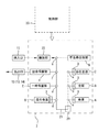
図1に示す本実施形態の紙葉類処理装置は、例えば乗車券やカード、精算切符等の券売を行う券売機として用いられるもので、紙幣ブロック1と、これにセットされて紙幣の収納場所となる4つの金庫A〜Dと、投入される紙幣の金種を識別部22で識別して金庫A〜Dのうち対応する金庫に搬送経路21を介して搬送する搬送手段2とを具備する。
The paper sheet processing apparatus of this embodiment shown in FIG. 1 is used as, for example, a ticket vending machine that sells tickets, cards, check-out tickets, etc., and is stored in a banknote block 1 and a banknote storage place. And the transport means 2 for identifying the denomination of the inserted bill by the
紙幣ブロック1は、利用者に近い側に挿入口11、出金口13、返却口14(以下、出金口13及び返却口14を合わせて払出口12ともいう)を設けたもので、同じく利用者に近い側に固定式の混合金庫Dを内設し、係員が操作を行う側方に三つのカセット式の金庫A〜Cを設けている。また、紙幣ブロック1には、搬送経路21上の紙幣を一時的に保留する一時保留部Eや出金保留部F、読み取り不能、重送発生、異常検知時の不良券を回収する不良券回収部G等も設けられている。カセット式の金庫A〜Cは、図2に例示するように把手hを把持して引き出すことが可能とされた着脱可能な金庫である。
The banknote block 1 is provided with an
識別部22は、図1及び図3に示すように、紙幣の金種判定を主として行うもので、挿入口11から投入される紙幣の金種のみ識別する。これに対して、各金庫A〜Dに紙幣が補給される場合や、各金庫A〜Dから紙幣が回収される場合等には、図1及び図3に示す補給回収用の簡易型の識別部20(以下、簡易識別部と称する)で金種識別を行う。ここに言う簡易型とは、金種識別のみを行い、紙幣の真性(偽造か否か)までは識別しないものを言う。
As shown in FIGS. 1 and 3, the
搬送手段2は、図3に示すように、周知の紙幣処理装置と同様に、図示しない挾持ローラ、搬送ベルト、ウィング等の方向変換部などから構成される前記搬送経路21と、搬送される紙幣の金種を識別する前記識別部22および簡易識別部20と、この識別部22或いは簡易識別部20の識別結果等に基づいて前記搬送経路21を制御する制御部23(図3参照)とから構成される。制御部23は、CPU、メモリ及びインターフェイスを具備する通常のマイクロコンピュータにより構成され、この制御部23が、挿入口11から投入された紙幣を識別部22に通過させた後、搬送経路21に沿って流通させ、随所に設けた分岐部a〜gで必要に応じて紙幣を方向変換して、金庫A〜D、一時保留部E、出金保留部F、払出口12、一次保留部a1〜c1、不良券回収部G等へ搬送する動作を行うとともに、金庫A〜D等から搬送経路21上への紙幣の繰り出し動作、簡易識別部20における金種識別、更には次なる搬送先である払出口12や金庫A〜Dへの搬送動作などを含む統括的な制御を行うように構成されている。
As shown in FIG. 3, the
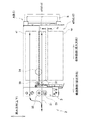
各金庫A(B、C)には、図4に示すように、紙幣等の紙葉類を積み重ねた束状態で収納可能な一次保留部a1(b1、c1)及び収納部a2(b2、c2)が形成されている。この収納部a2(b2、c2)には、図示しない駆動モータの動力で上下に往復運動するフォークを用いた往復移動部foが設けられており、この往復移動部foは、収納部a2を構成する壁面wl(図7〜図9参照)に包囲される集積空間spを上下二つの空間に区画し、上方の空間を紙葉類を一時的に保留するための二次保留部a3(b3、c3)に設定している。そして、これら各部a1、a2及びa3によって、取引時には、図3に示す挿入口11から投入された紙幣等の紙葉類を一次保留部a1(b1、c1)に一枚ずつ投入して取引確定時まで保留するとともに外部に対して払い出すための紙幣等の紙葉類を収納部a2(b2、c2)から一枚ずつ排出し、取引確定時には、一次保留部a1(b1、c1)から束状態の紙葉類を一括排出し、排出した紙葉類をベルト搬送により二次保留部a3(b3、c3)に一括投入して次取引開始時まで紙葉類を保留する運用を可能にしている。なお、収納部a2(b2、c2)には、収納されている紙葉類Paを上方(入出部分近傍)に向けて付勢するバックアッププレートbpが設けられている(図7〜図9参照)。
In each safe A (B, C), as shown in FIG. 4, a primary storage unit a1 (b1, c1) and a storage unit a2 (b2, c2) that can store paper sheets such as banknotes in a bundled state. ) Is formed. The storage part a2 (b2, c2) is provided with a reciprocating part fo using a fork that reciprocates up and down by the power of a drive motor (not shown). The reciprocating part fo constitutes the storage part a2. A storage space sp surrounded by a wall surface wl (see FIGS. 7 to 9) is divided into two upper and lower spaces, and a secondary storage portion a3 (b3, b) for temporarily storing the upper space in the upper space c3). Then, with each of these parts a1, a2 and a3, at the time of the transaction, paper sheets such as banknotes inserted from the
この運用を実現すべく、各金庫A〜Cには、図4に示すように、外部から搬送経路21を介して搬送される紙幣等の紙葉類Paを収納部a2に束状態で一括投入するとともに収納部a2内の紙葉類を一枚ずつ分離して搬送経路21に向かって排出するための投入分離機構3を設けている。
In order to realize this operation, as shown in FIG. 4, in each of the safes A to C, paper sheets Pa such as banknotes transported from the outside via the
投入分離機構3は、紙葉類Paの厚み方向両側に配置される駆動力を備えた対をなす投入ローラユニット32、33と、同様に対をなす第1のローラユニットであるフィードローラユニット30及び第2のローラユニットであるゲートローラユニット31と、ピックアップローラユニット34とを備え、これらのローラユニット30〜34で紙葉類Paを挟持しつつ紙葉類Paを投入方向、又は排出方向に付勢するように構成されている。
The input /
具体的には、フィードローラユニット30は、図5及び図6に示すように、金庫A(B、C)を足場として回転可能に取り付けられた回転シャフト30sと、この回転シャフト30sに固定した櫛ローラ30a〜30cと、回転シャフト30sに固定されたフィードギア30gとを主体とするもので、図示しないモータ等の駆動源の動力をフィードギア30gに伝達することにより回転軸Cn1回りに図5の矢印Y1方向又は矢印Y2方向に回転するものである。図5の矢印Y1方向は、紙葉類を投入方向に移動させる方向であり、図5のY2方向は、紙葉類を排出方向に移動させる方向である。
Specifically, as shown in FIGS. 5 and 6, the
ゲートローラユニット31は、図5及び図6に示すように、金庫A(B、C)を足場として回転シャフト31sを回転可能に支持する天秤部35と、回転シャフト31sに固定した櫛ローラ31a〜31bと、回転シャフト31sに固定され上記フィードギア30gに噛み合うゲートギア31gとを主体とするもので、ゲートギア31gを図示しないワンウェイクラッチを介して回転シャフト31sに装着するとともに回転シャフト31sを図示しないワンウェイクラッチを介して天秤部35に支持させることで、フィードローラユニット30が図5の矢印Y1方向(紙葉類を投入方向に移動させる方向)に回転した場合のみゲートローラユニット31が図5の矢印Y3方向(紙葉類を投入方向に移動させる方向)に従動回転し、フィードローラユニット30が図5の矢印Y2方向(紙葉類を排出方向に移動させる方向)に回転した場合にはゲートローラユニット31が回転せずに停止状態を維持するように構成されている。天秤部35は、フィードローラユニット30の回転軸Cn1とほぼ平行な回転軸Cn3を中心に回動自在になるように金庫A(B、C)に取り付けられており、フィードローラユニット30及びゲートローラユニット31を相対的に遠近自在にしている。天秤部35は、図示しないコイルバネにより図7及び図8に示す矢印Y4方向、すなわちゲートローラユニット31をフィードローラユニット30へ近づける方向へ付勢されている。この付勢力は、図7に示すように、束にした紙葉類Pa(Stack)が収納部a2へ投入される際には、ゲートローラユニット31が束の紙葉類Pa(Stack)に押下されて、フィードローラユニット30及びゲートローラユニット31が離間する強さに設定されている。
As shown in FIGS. 5 and 6, the
そして、図7に示すように、フィードローラユニット30及びゲートローラユニット31が紙葉類を投入方向に移動させる方向(順に矢印Y1方向、矢印Y3方向)にそれぞれ回転することで投入ローラユニット32、33により搬送された束状態の紙葉類Pa(Stack)が収納部a2に投入される。一方、図8に示すように、フィードローラユニット30が紙葉類Paを排出方向に移動させる方向(矢印Y1方向)に回転するとともにゲートローラユニット31が停止状態を維持することで紙葉類Paが二枚以上重送された場合に重送された紙葉類Paを分離して収納部a2内に留め、紙葉類Paが一枚ずつ排出される。勿論、紙葉類Paの排出時にゲートローラユニット31を紙葉類Paを投入方向に移動させる方向に回転させるように構成してもよい。なお、図7及び図8に示すように、フィードローラユニット30のY1方向への回転に伴って紙葉類Paが巻き上げられることを防止するシャフト等の棒状の巻き上げ防止部材38を、投入する紙葉類Paを挟んでゲートローラユニット31と対向する側であり、フィードローラユニット30よりも収納部a2寄りの位置であって、後述の羽根ローラ部40、41が回転する際に側面視において羽根ローラ部が有する羽根部40a、40b、41a、41bと重なり合う位置に設けるとともに、フィードローラユニット30の回転軸Cn1よりも紙葉類Paに近接した部分を備えるように構成してもよい。巻き上げ防止部材38の形状は、紙葉類Paの巻き上げを規制することができれば、棒状に限られず、例えば板状が挙げられる。
Then, as shown in FIG. 7, the
一対のフィードローラユニット30及びゲートローラユニット31は、図6に示すように、フィードローラユニット30の櫛ローラ30a〜30cと、ゲートローラユニット31の櫛ローラ31a〜31bとを回転軸の径方向にオーバーラップさせて紙葉類Paを挟む構成をなしており、このオーバーラップ量lapを適度に設定することによって紙葉類を一枚ずつ分離して排出する分離機能を担保している。
As shown in FIG. 6, the pair of
ところで、本実施形態では、図9(a)に示すように、取引確定時に紙葉類Paを二次保留部a3(b3、c3)に投入して次取引開始時まで紙葉類Paを往復移動部fo上に保留し、次取引開始時に、図9(b)及び図9(c)に示すように、往復移動部foを一旦上方に移動させて、幅方向両端が往復移動部foに支持される紙葉類Paと収納部a2に固定している上部固定板fpとを当接させ、この紙葉類Paを往復移動部foの隙間から下方にすり抜けさせて、紙葉類Paを収納部a2(b2、c2)に収め、往復移動部foを再び下方に下げて、次の紙葉類Paの投入に備える動作を行うものである。この場合、図9(a)に示すように、投入された紙葉類Paが完全に集積空間sp(二次保留部a3)に収まらずに集積空間spからはみ出している状態でフォーク等の往復移動部foを図9(a)→図9(b)→図9(c)のように移動させると、収納部a2を構成する壁面wlで紙葉類Paが折れ曲がることがあり、この折れはジャム等の集積不良や繰り出し不良を引き起こす原因となる。この問題は、本実施形態のような動作を行う収納部a2(b2、c2)に限らず、他の形態の収納部でも起こりうることである。 By the way, in this embodiment, as shown in FIG. 9A, when the transaction is confirmed, the paper sheet Pa is inserted into the secondary holding unit a3 (b3, c3), and the paper sheet Pa is reciprocated until the next transaction starts. As shown in FIGS. 9 (b) and 9 (c), the reciprocating unit fo is temporarily moved upward at the beginning of the next transaction, and both ends in the width direction are moved to the reciprocating unit fo. The supported paper sheet Pa and the upper fixing plate fp fixed to the storage part a2 are brought into contact with each other, and the paper sheet Pa is slipped downward from the gap of the reciprocating movement part fo to remove the paper sheet Pa. It is stored in the storage section a2 (b2, c2), and the reciprocating movement section fo is lowered again to perform an operation for preparing the next paper sheet Pa. In this case, as shown in FIG. 9A, the fork or the like is reciprocated in a state where the input paper sheet Pa does not completely fit in the accumulation space sp (secondary holding part a3) and protrudes from the accumulation space sp. When the moving part fo is moved as shown in FIG. 9 (a) → FIG. 9 (b) → FIG. 9 (c), the paper sheet Pa may be bent at the wall surface wl constituting the storage part a2. This may cause an accumulation failure such as a jam or a feeding failure. This problem is not limited to the storage unit a2 (b2, c2) that performs the operation as in the present embodiment, but may occur in other types of storage units.
そこで、これを防止すべく、投入される紙葉類Paを的確且つ適切に集積空間spに移動させるために、図5及び図6に示すように、フィードローラユニット30の回転シャフト30sに複数の羽根ローラ部40、41を設けている(図5では羽根ローラ部41を模式的に示している)。羽根ローラ部40、41は、弾性部材からなり可燒性を有する羽根部40a、40b(41a、41b、図8〜図10参照)が周方向に沿って放射状に複数形成されており、図7に示すように、フィードローラユニット30の回転軸Cn1回りにフィードローラユニット30と共に回転し、投入される紙葉類Paを収納部a2内の集積空間spへはき出すものである。
In order to prevent this, in order to move the input paper sheet Pa to the accumulation space sp accurately and appropriately, a plurality of
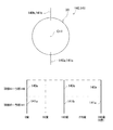
羽根ローラ部40、41は、図5及び図6に示すように、フィードローラユニット30の回転シャフト30sに沿って、すなわち紙葉類Paの幅方向に沿って複数配置されており、櫛ローラ30a〜30cの両側にある各羽根ローラ部40、41の羽根部(40a、40b、41a、41b)のうち対応する羽根部同士(40aと41a、40bと41b)が周方向における位置が互いに異なるように配置されている。具体的には、図10に示すように、フィードローラユニットを360度回転させるにあたり、真下(紙葉類Pa側)を向く羽根部と回転角度との関係を、或る回転角度を0度として説明すると、0度で羽根部40aが真下を向き、90度で羽根部41aが真下を向き、180度で羽根部40bが真下を向き、270度で羽根部41bが真下を向くように羽根部(40a、40b、41a、41b)の位相関係が規定されている。すなわち、同時に複数の羽根部が真下(紙葉類Pa側)を向かないようにし、羽根ローラ部40、41が紙葉類Paをゲートローラユニット31に向けて押す押圧力を低減させている。
As shown in FIGS. 5 and 6, a plurality of
以上のように、本実施形態に係る紙葉類処理装置は、紙葉類Paを収納する収納部a2と、紙葉類Pa(Stack)を収納部a2に投入して収納すると共に収納された紙葉類Paを一枚ずつ分離して排出する投入分離機構3とを具備してなり、投入分離機構3は、厚み方向両側に配置された一対の第1のローラユニットであるフィードローラユニット30及び第2のローラユニットであるゲートローラユニット31を有し、両ローラユニット30、31が紙葉類Paを投入方向に移動させる方向(Y1方向、Y3方向)にそれぞれ回転することで紙葉類Paを投入する一方、第1のローラユニットであるフィードローラユニット30が紙葉類Paを排出方向に移動させる方向(Y2方向)に回転するとともに第2のローラユニットであるゲートローラユニット31が停止することで紙葉類Paを一枚ずつ分離して排出するように構成されており、投入される紙葉類Paを収納部a2内の集積空間spへはき出すための弾性部材からなる羽根部(40a、40b、41a、41b)を有する羽根ローラ部40、41が第1のローラユニットであるフィードローラユニット30の回転軸Cn3回りに第1のローラユニットであるフィードローラユニット30と共に回転可能に設けられている。
As described above, the sheet processing apparatus according to the present embodiment stores and stores the storage unit a2 that stores the sheet Pa and the storage unit a2 that stores the sheet Pa (Stack). And a
このように構成すると、紙葉類Paの投入時に弾性部材からなる羽根部(40a、40b、41a、41b)を有する羽根ローラ部40、41が、紙葉類Paを投入方向に移動させるフィードローラユニット30と共に同軸Cn1回りに回転することで投入される紙葉類Paを収納部a2内の集積空間spへはき出し、紙葉類Paを適切に収納部a2に投入する一方で、紙葉類Paの排出時に羽根ローラ部40、41が、紙葉類Paを排出方向に移動させるフィードローラユニット30と共に同軸Cn1回りに回転するので、羽根ローラ部40、41が紙葉類Paの進路を妨げず、紙葉類Paと羽根ローラ部40、41との干渉に起因するミスフィード等の紙葉類Paの排出不良を防止することが可能となる。しかも、羽根ローラ部40、41が紙葉類Paの進路を妨げないので、進路妨害に起因する排出不良を低減するために羽根ローラ部40、41の羽根部(40a、40b、41a、41b)の数を減らしたり羽根部(40a等)の剛性を下げたりする必要がなくなり、羽根部(40a等)の数を減らすことにより集積空間spへの退避が間に合わずにジャム等の集積不良が生じることを回避し又は羽根ローラ部40、41が紙葉類Paを集積空間spへはき出す力を低減することを回避して、紙葉類Paを的確に収納部a2に投入することが可能となる。
If comprised in this way, the feed roller which has the blade |
特に、本実施形態は、紙葉類Paの排出時にゲートローラユニット31を停止状態にするものであり、羽根ローラ部40、41をゲートローラユニット31ではなくフィードローラユニット30に設けているので、紙葉類Paの排出時に羽根ローラ部40、41が紙葉類Paの進路を妨げない姿勢にゲートローラユニット31を位置決め制御する複雑な機構を設ける必要がなくなり、上記搬送不良を防止する構成を、装置の小型化及び製造コストの低減を図りつつ簡易な構成で実現することが可能となる。この場合、ゲートローラユニット31が任意の回転姿勢で停止可能となるので、ゲートローラユニット31を常に一定の姿勢で停止することでゲートローラユニット31の櫛ローラ31a〜31bが局所的に摩耗してしまう偏摩耗を防止し、偏摩耗による分離機能の低減を防止することが可能となる。
Particularly, in the present embodiment, the
さらに、本実施形態では、羽根ローラ部40、41をゲートローラユニット31ではなくフィードローラユニット30に設けているので、紙葉類Paが排出される際に羽根ローラ部40、41によってゲートローラユニット31に向けて多少なりとも押圧され、この押圧力の大きさによって新たに紙葉類Paの排出不良が生じるおそれが考えられるものの、本実施形態では、羽根ローラ部40、41が紙葉類Paの幅方向に沿って複数設けられており、各々の羽根ローラ部40、41に形成される羽根部(40a、40b、41a、41b)は、周方向における位置が互いに異なるように配置されているので、複数の羽根部40a、40bが同時に紙葉類Paを押圧することを低減又は無くすることができ、羽根ローラ部40、41による押圧力を低減させて紙葉類Paの排出不良を低減することが可能となる。
Furthermore, in this embodiment, since the
その他、本実施形態では、両ローラユニット30、31は、互いに径方向にオーバーラップさせて紙葉類Paを挟む櫛ローラ30a〜30c、31a〜31bをそれぞれ有し、これら櫛ローラ30a〜30c、31a〜31b間のオーバーラップ量lapによって適切な分離機能を担保するものであるので、偏摩耗により適切な分離機能が損なわれることを適切に防止している。
In addition, in this embodiment, both
以上、本発明の実施形態について図面に基づいて説明したが、具体的な構成は、これらの実施形態に限定されるものでないと考えられるべきである。本発明の範囲は、上記した実施形態の説明だけではなく特許請求の範囲によって示され、さらに特許請求の範囲と均等の意味および範囲内でのすべての変更が含まれる。 As mentioned above, although embodiment of this invention was described based on drawing, it should be thought that a specific structure is not limited to these embodiment. The scope of the present invention is shown not only by the above description of the embodiments but also by the scope of claims for patent, and further includes all modifications within the meaning and scope equivalent to the scope of claims for patent.
例えば、本実施形態では、複数の羽根ローラ部40、41のうち羽根部同士(40a、40b、41a、41b)を周方向における位置が互いに異なるように配置しているが、図11に示すように、複数の羽根ローラ部140、141のうち対応する羽根部同士(140aと141a、140bと141b)を周方向における位置が一致するように配置してもよい。このように構成すると、同時に複数の羽根部(140aと141a、140bと141b)が真下(紙葉類Pa側)を向くので、紙葉類Paを幅方向の複数点で把持して確実にはき出すことが可能となる。
For example, in the present embodiment, the blade portions (40a, 40b, 41a, 41b) among the plurality of
また、本実施形態のフィードローラユニット30には、羽根ローラ部40、41が複数設けられているが、第1のローラユニットに設けられる羽根ローラ部の数は単一であってもよい。
In addition, the
さらに、本実施形態の投入分離機構3は、積み重ねた束状態の紙葉類Paを収納部a2に投入しているが、図12に示すように、紙葉類を一枚ずつ連続して投入する投入分離機構303に適用可能である。この場合、投入された紙葉類が後続の紙葉類と干渉することを防止するために、投入された紙葉類を後続の紙葉類が投入されるまでに羽根ローラ部によって後続の紙葉類との干渉が回避される退避位置に移動させる必要があり、これを実現するためには羽根ローラ部に多数の羽根部が周方向に形成されていることが望ましいので、羽根部の数を減らすことなく紙葉類Paの排出不良を低減可能である意味で、本発明の適用が好ましい。勿論、本実施形態のように、積み重ねた束状態の紙葉類を収納部に一括投入する投入分離機構に対する適用を妨げるものではない。
Furthermore, the loading /
加えて、本実施形態では、ベルト搬送を用いて紙葉類を搬送しているが、ベルト搬送を用いないものにも適用可能である。例えば図12に示す搬送ローラ37を搬送経路21に対して千鳥状に配置したものが挙げられる。また、本実施形態では、投入分離機構として、ゲートローラ方式を採用しているが、これに限定されるものではない。例えばFRR方式を用いたものが挙げられる。
In addition, in the present embodiment, paper sheets are conveyed using belt conveyance, but the present invention can also be applied to those that do not use belt conveyance. For example, one in which the
その他、本実施形態では、紙葉類を紙幣Paとしているが、乗車券やカード、精算切符等のその他の紙葉類に適用してもよい。 In addition, in this embodiment, although paper sheets are made into the banknote Pa, you may apply to other paper sheets, such as a boarding ticket, a card | curd, and a check-out ticket.
なお、各部の具体的な構成は、上述した実施形態のみに限定されるものではなく、本発明の趣旨を逸脱しない範囲で種々変形が可能である。 The specific configuration of each part is not limited to the above-described embodiment, and various modifications can be made without departing from the spirit of the present invention.
3…投入分離機構
30…第1のローラユニット(フィードローラユニット)
31…第2のローラユニット(ゲートローラユニット)
40、41、140、141…羽根ローラ部
40a、40b、41a、41b、141a、141b、140a、140b…羽根部
a2…収納部
Pa…紙葉類(紙幣)
sp…集積空間
3...
31 ... Second roller unit (gate roller unit)
40, 41, 140, 141 ...
sp ... Accumulation space
Claims (2)
前記投入分離機構は、厚み方向両側に配置された第1のローラユニットと第2のローラユニットとからなる一対のローラユニットを有し、両ローラユニットが紙葉類を投入方向に移動させる方向にそれぞれ回転することで紙葉類を投入する一方、前記第1のローラユニットが紙葉類を排出方向に移動させる方向に回転するとともに前記第2のローラユニットが停止又は紙葉類を投入方向に移動させる方向に回転することで紙葉類を一枚ずつ分離して排出するように構成されており、
投入される紙葉類を前記収納部内の集積空間へはき出すための弾性部材からなる羽根部を有する羽根ローラ部が前記第1のローラユニットの回転軸回りに当該第1のローラユニットと共に回転可能に設けられ、
紙葉類を投入する際の第1のローラユニットの回転に伴う紙葉類の巻き上げを規制するための巻き上げ防止部材が、投入する紙葉類を挟んで前記第2のローラユニットと対向する側であり、前記第1のローラユニットよりも前記収納部寄りの位置であって、前記羽根ローラ部が回転する際に側面視において前記羽根部と重なりあう位置に設けられるとともに、前記第1のローラユニットの回転軸よりも紙葉類に近接した部分を備えるように構成されていることを特徴とする紙葉類処理装置。 A paper sheet comprising: a storage unit that stores paper sheets; and a loading separation mechanism that inputs and stores the paper sheets into the storage unit and separates and discharges the stored paper sheets one by one. A processing device,
The closing separation mechanism includes a pair of roller units including a first roller unit and the second roller units arranged in both sides in the thickness direction, in the direction of the rollers unit moves the paper sheet in the charging direction While rotating the paper sheets, the first roller unit rotates in the direction of moving the paper sheets in the discharging direction and the second roller unit stops or puts the paper sheets in the loading direction. It is configured to separate and discharge paper sheets one by one by rotating in the moving direction,
A blade roller portion having a blade portion made of an elastic member for ejecting input paper sheets into the accumulation space in the storage portion is rotatable around the rotation axis of the first roller unit together with the first roller unit. Provided ,
The side where the roll-up preventing member for restricting the roll-up of the paper sheet accompanying the rotation of the first roller unit when the paper sheet is input faces the second roller unit across the paper sheet to be input The first roller unit is provided at a position closer to the storage portion than the first roller unit and at a position overlapping the blade portion in a side view when the blade roller portion rotates. A paper sheet processing apparatus , comprising a portion closer to the paper sheet than the rotation axis of the unit.
A plurality of the blade roller portions are provided along the width direction of the paper sheet, and the blade portions formed in each blade roller portion are arranged so that positions in the circumferential direction are different from each other. The paper sheet processing apparatus according to 1.
Priority Applications (1)
| Application Number | Priority Date | Filing Date | Title |
|---|---|---|---|
| JP2010080680A JP5585169B2 (en) | 2010-03-31 | 2010-03-31 | Paper sheet processing equipment |
Applications Claiming Priority (1)
| Application Number | Priority Date | Filing Date | Title |
|---|---|---|---|
| JP2010080680A JP5585169B2 (en) | 2010-03-31 | 2010-03-31 | Paper sheet processing equipment |
Publications (2)
| Publication Number | Publication Date |
|---|---|
| JP2011213424A JP2011213424A (en) | 2011-10-27 |
| JP5585169B2 true JP5585169B2 (en) | 2014-09-10 |
Family
ID=44943583
Family Applications (1)
| Application Number | Title | Priority Date | Filing Date |
|---|---|---|---|
| JP2010080680A Expired - Fee Related JP5585169B2 (en) | 2010-03-31 | 2010-03-31 | Paper sheet processing equipment |
Country Status (1)
| Country | Link |
|---|---|
| JP (1) | JP5585169B2 (en) |
Family Cites Families (4)
| Publication number | Priority date | Publication date | Assignee | Title |
|---|---|---|---|---|
| JPH09226950A (en) * | 1996-02-22 | 1997-09-02 | Shibaura Eng Works Co Ltd | Paper sheet processor |
| JP4551675B2 (en) * | 2004-03-08 | 2010-09-29 | 株式会社東芝 | Paper sheet processing equipment |
| JP2008063025A (en) * | 2006-09-05 | 2008-03-21 | Hitachi Omron Terminal Solutions Corp | Paper sheet handling device |
| JP5034514B2 (en) * | 2007-01-23 | 2012-09-26 | 富士電機リテイルシステムズ株式会社 | How to pay out vertically stored bills |
-
2010
- 2010-03-31 JP JP2010080680A patent/JP5585169B2/en not_active Expired - Fee Related
Also Published As
| Publication number | Publication date |
|---|---|
| JP2011213424A (en) | 2011-10-27 |
Similar Documents
| Publication | Publication Date | Title |
|---|---|---|
| JP5274999B2 (en) | Banknote handling equipment | |
| JP4292012B2 (en) | Banknote deposit and withdrawal device | |
| JP3861007B2 (en) | Banknote deposit and withdrawal device and automatic cash transaction device | |
| US9183691B2 (en) | Banknote pay-in/pay-out device and banknote processing machine | |
| JP5388265B2 (en) | Paper sheet processing equipment | |
| WO2017042965A1 (en) | Paper sheet storage and discharge device | |
| JP6710353B2 (en) | Banknote handling device | |
| JP6381343B2 (en) | Paper sheet storage and feeding device | |
| JP6547344B2 (en) | Medium storage and medium handling device | |
| JP5585169B2 (en) | Paper sheet processing equipment | |
| JP6776667B2 (en) | Media storage device and media trading device | |
| JP5176041B2 (en) | Paper sheet feeding mechanism, reflux-type bill storage device, bill processing device, and bill handling device | |
| JP3658268B2 (en) | Paper sheet stacking device, paper sheet storage, and paper sheet handling device | |
| WO2017042966A1 (en) | Paper sheets processing machine and bill processing machine | |
| JP6497193B2 (en) | Medium processing apparatus and medium transaction apparatus | |
| JP2011213423A (en) | Paper sheet processing device | |
| JP6399845B2 (en) | Paper sheet processing machine | |
| JP2007041826A (en) | Paper money receiving/paying machine and automatic cash transaction device | |
| KR20090012510U (en) | A belt type paper money counting machine | |
| JP5589349B2 (en) | Paper sheet processing equipment | |
| JP4551675B2 (en) | Paper sheet processing equipment | |
| JP4779453B2 (en) | Bill collecting device and transaction processing device | |
| JP2004010346A (en) | Paper sheets conveyance device, paper sheets storage unit, paper money dealing device and automatic cash money transaction device | |
| JP2007087403A (en) | Bank bill storage/discharge cabinet | |
| JP2007219751A (en) | Paper money reception/payment port |
Legal Events
| Date | Code | Title | Description |
|---|---|---|---|
| A621 | Written request for application examination |
Free format text: JAPANESE INTERMEDIATE CODE: A621 Effective date: 20130219 |
|
| A977 | Report on retrieval |
Free format text: JAPANESE INTERMEDIATE CODE: A971007 Effective date: 20131127 |
|
| A131 | Notification of reasons for refusal |
Free format text: JAPANESE INTERMEDIATE CODE: A131 Effective date: 20131203 |
|
| A521 | Written amendment |
Free format text: JAPANESE INTERMEDIATE CODE: A523 Effective date: 20140130 |
|
| TRDD | Decision of grant or rejection written | ||
| A01 | Written decision to grant a patent or to grant a registration (utility model) |
Free format text: JAPANESE INTERMEDIATE CODE: A01 Effective date: 20140624 |
|
| A61 | First payment of annual fees (during grant procedure) |
Free format text: JAPANESE INTERMEDIATE CODE: A61 Effective date: 20140707 |
|
| R150 | Certificate of patent or registration of utility model |
Ref document number: 5585169 Country of ref document: JP Free format text: JAPANESE INTERMEDIATE CODE: R150 |
|
| LAPS | Cancellation because of no payment of annual fees |