JP5583732B2 - Auxiliary attachment device for accumulator connector and method for connecting conductor using accumulator connector - Google Patents
Auxiliary attachment device for accumulator connector and method for connecting conductor using accumulator connector Download PDFInfo
- Publication number
- JP5583732B2 JP5583732B2 JP2012222002A JP2012222002A JP5583732B2 JP 5583732 B2 JP5583732 B2 JP 5583732B2 JP 2012222002 A JP2012222002 A JP 2012222002A JP 2012222002 A JP2012222002 A JP 2012222002A JP 5583732 B2 JP5583732 B2 JP 5583732B2
- Authority
- JP
- Japan
- Prior art keywords
- power storage
- groove
- bolt
- storage connector
- connector
- Prior art date
- Legal status (The legal status is an assumption and is not a legal conclusion. Google has not performed a legal analysis and makes no representation as to the accuracy of the status listed.)
- Expired - Fee Related
Links
- 239000004020 conductor Substances 0.000 title claims description 41
- 238000000034 method Methods 0.000 title claims description 26
- WABPQHHGFIMREM-UHFFFAOYSA-N lead(0) Chemical compound [Pb] WABPQHHGFIMREM-UHFFFAOYSA-N 0.000 claims description 45
- 238000003860 storage Methods 0.000 claims description 41
- 238000003780 insertion Methods 0.000 claims description 27
- 230000037431 insertion Effects 0.000 claims description 27
- 238000004146 energy storage Methods 0.000 claims description 22
- 238000009825 accumulation Methods 0.000 claims description 10
- 230000005489 elastic deformation Effects 0.000 claims description 4
- 230000008569 process Effects 0.000 description 7
- 230000001105 regulatory effect Effects 0.000 description 5
- 241000282693 Cercopithecidae Species 0.000 description 3
- 230000000694 effects Effects 0.000 description 3
- 238000004519 manufacturing process Methods 0.000 description 2
- 230000004048 modification Effects 0.000 description 2
- 238000012986 modification Methods 0.000 description 2
- 238000012790 confirmation Methods 0.000 description 1
- 230000006866 deterioration Effects 0.000 description 1
- 238000010586 diagram Methods 0.000 description 1
- 230000006872 improvement Effects 0.000 description 1
- 239000000463 material Substances 0.000 description 1
- 239000002184 metal Substances 0.000 description 1
- 230000000149 penetrating effect Effects 0.000 description 1
- 230000002093 peripheral effect Effects 0.000 description 1
- 238000003825 pressing Methods 0.000 description 1
- 230000002265 prevention Effects 0.000 description 1
- 230000009467 reduction Effects 0.000 description 1
- 239000011347 resin Substances 0.000 description 1
- 229920005989 resin Polymers 0.000 description 1
- 238000000926 separation method Methods 0.000 description 1
- 238000005406 washing Methods 0.000 description 1
- 239000002023 wood Substances 0.000 description 1
Images


Description
本発明は、二本の導線、例えば高圧計器の計器用変成器のリード線と一次配線とを蓄力コネクタで接続する作業を支援する蓄力コネクタの装着補助器具、及び蓄力コネクタを用いた導線接続方法に関する。 The present invention uses an accumulator connector mounting assisting device and an accumulator connector that support the work of connecting two lead wires, for example, a lead wire of an instrument transformer of a high voltage meter and a primary wiring with the accumulator connector. The present invention relates to a conductor connection method.
二本の導線を電気的機械的に接続するツールとして従来から蓄力コネクタが用いられている。例えば図10に示すように蓄力コネクタ51は、高圧計器の計器用変成器(以下、変成器31という)のリード線32と一次配線41とを接続する用途に用いられる。つまり蓄力コネクタ51は、共に導線であるリード線32と一次配線41とを電気的機械的に接続する。図10中、11はキュービクルであり、そのハウジング12に変成器31が収納されている。変成器31の負荷側のリード線32を一次配線41と接続するのが蓄力コネクタ51である。蓄力コネクタ51には高圧用端子カバー61が被される。変成器31の電源側のリード線33はビット22を案内されてきた高圧ケーブル21に接続されている。ハウジング12内において高圧ケーブル21はブランケット23に支持されている。
Conventionally, a power storage connector is used as a tool for electrically and mechanically connecting two conductive wires. For example, as shown in FIG. 10, the
図11(a)〜(d)に示すように蓄力コネクタ51は、ボルト52と蓄力座金PBを備えるナット53とを組み合わせた構造のものである。ボルト52は二股に分岐した形状で、その根元部分に平べったいヘッド54を有し、二股に分岐した部分の外周面にネジ55を有し、二股に分岐した部分の間にU溝56を形成している。このU溝56は、接続する二本の導線、例えばリード線32と一次配線41とを差し込むための空間である。ナット53は、ボルト52のU溝56に蓄力座金PBを差し込んでネジ55に螺合する。蓄力座金PBは、ナット53に回転自在に取り付けた基体57に対して、加圧体58を回り止めした状態で接離自在に取り付けた構造のものである。基体57はストッパ59によってナット53から脱落しないようにされており、加圧体58は基体57から離反する方向に付勢されている。加圧体58を付勢しているのはコイルスプリングである(図示せず)。つまり蓄力座金PBは、基体57と加圧体58との間に圧縮状態でコイルスプリングを内蔵し、その伸び力によって基体57から離反する方向に加圧体58を付勢している。
As shown in FIGS. 11A to 11D, the
図12に示すように蓄力コネクタ51は、リード線32と一次配線41とを締め付けることによって電気的機械的に接続している。このような状態とするためには、ボルト52のU溝56にリード線32を差し込み、続いて一次配線41を差し込み、ボルト52のネジ55にナット53を螺合する。この時、ナット53に取り付けられた蓄力座金PBがU溝56に差し込まれるので、ナット53を締め付けることによって蓄力座金PBの加圧体58がリード線32と一次配線41とに加圧力を加える。これによってリード線32と一次配線41とが締め付けられて接続されるわけである。
As shown in FIG. 12, the
以上説明したような蓄力コネクタによる二本の導線の接続手法については、例えば特許文献1、2にも記載されている。 For example, Patent Documents 1 and 2 describe the connection method of two conductive wires using the power storage connector as described above.
二本の導線を蓄力コネクタで接続する際の作業性について考える。ここではまず現場の作業環境について検討し、続いて実際の作業内容を確認した後、これらの検討事項及び確認事項を考慮した上で作業性の良否を評価する。併せて作業性を原因として生ずる問題点についても言及する。 Consider the workability when connecting two wires with a power storage connector. Here, the work environment at the site is first examined, and after confirming the actual work contents, the quality of workability is evaluated after taking into consideration these examination items and confirmation items. At the same time, we will mention the problems caused by workability.
(1)現場の作業環境
まず注目すべきことは、二本の導線を蓄力コネクタで接続する際、良好な環境で作業ができるとは限らないということである。例えば変成器のリード線と一次配線とを接続する作業を想定すると、その作業環境は必ずしも良好とは言えない。変成器は一般的に電柱の柱上、電気所の電気室、キュービクル内などの作業がしにくい場所に設置されているからである。
(1) On-site work environment First of all, it should be noted that when two conductors are connected by a power storage connector, it is not always possible to work in a good environment. For example, assuming the work of connecting the lead wire of the transformer and the primary wiring, the working environment is not necessarily good. This is because the transformer is generally installed in a place where it is difficult to work, such as on the pole of an electric pole, in an electric room of an electric station, or in a cubicle.
例えば電柱の柱上に設置されている変成器が作業対象である場合、作業者は電柱の上という不安定な場所での作業を強いられる。また電気室では変成器の周辺空間が狭小であることが多いため、作業者は思うまま自由に手を入れることができない。この点はキュービクル内に設置されている変成器も事情が同じである。 For example, when a transformer installed on a power pole is a work target, the worker is forced to work in an unstable place on the power pole. In addition, in the electrical room, the space around the transformer is often narrow, so the operator cannot freely get his hands. The situation is the same for the transformer installed in the cubicle.
キュービクルについては図10を参照すると分かり易い。図10を見ると、ハウジング12の内壁と変成器31との間の空間が狭小であることが分かる。これは何も図10に特殊な状態を示してありもしない問題を掘り起こそうと意図しているわけではない。図10に示す状態はごくごく一般的なキュービクル事情である。しかも図10ではリード線32と一次配線41とを一組しか示していないが、実際には複数組のリード線32と一次配線41との組みが奥にも続いており、それぞれ蓄力コネクタ51での接続を要する。したがってキュービクル11に設置されている変成器31においては、狭い空間に手を入れてリード線32と一次配線41とを接続しなければならない。良好な作業環境にはほど遠い。
The cubicle can be easily understood with reference to FIG. Referring to FIG. 10, it can be seen that the space between the inner wall of the
(2)実際の作業内容
二本の導線を蓄力コネクタで接続する際の実際の作業の内容を確認する。ここでは一般的な内容を確認するわけであるが、分かり易いように図10ないし図12の符号を用いて説明する。
(2) Actual work content Check the actual work content when connecting two conductors with a power storage connector. Here, the general contents are confirmed, but the description will be made with reference to FIGS. 10 to 12 for easy understanding.
蓄力コネクタ51で二本の導線、例えばリード線32と一次配線41とを接続するに際してはまず、ボルト52のヘッド54をモンキーレンチやラチェット、あるいはペンチやスパナなどを用いてしっかりと把持する。続いてこの状態を保ったままU溝56に二本の導線を順に差し込み、その上から蓄力座金PBをさらに差し込んでネジ55にナット53を螺合させる。そしてヘッド54を把持して回り止めしたまま、モンキーレンチやスパナなどを用いてナット53を締め付ける。こうして二本の導線が接続される。両手に工具を持ち、しかもそれらの工具を操作し続けての作業となるわけである。
When connecting the two conducting wires, for example, the
これに加えて、二本の導線を蓄力コネクタ51で接続するに際しては、各部の寸法管理も必要となる。変成器31のリード線32と一次配線41とを接続する場合を例に挙げると、例えば図13に一例を示すように、二つの蓄力コネクタ51の間の間隔を20mm、導線先端と先端側の蓄力コネクタ51との間の距離を20mm、被覆部32a及び41aの端部と根元側のヘッド54との間の距離を10mm、そして被覆部32a及び41aの先端と高圧用端子カバー61の端部との間の距離を25mm以上というような寸法管理が求められる。ここでの数値は個別具体的な一例を示しているに過ぎないが、安全上の観点から同種の寸法管理が求められることには普遍性がある。例えば電力事業者は通常、上記寸法管理に関する内部規定を定めている。
In addition to this, when connecting the two conducting wires with the
(3)作業性
以上述べたように、二本の導線を蓄力コネクタで接続する際の作業環境はあまり良好とは言えない。その一方で実際の作業に当たっては両手に工具を持ち、しかもそれらの工具を操作し続けての作業となる。これに加えて比較的厳格な寸法管理も求められる。こうして現場の作業環境に思いを馳せつつ実際の作業内容を見てくると、その作業性が極めて悪いことに気がつく。何らかの改善が求められるところである。
(3) Workability As described above, it cannot be said that the work environment when connecting two conductive wires with a power storage connector is very good. On the other hand, in the actual work, the tool is held in both hands and the tools are continuously operated. In addition, relatively strict dimensional control is also required. In this way, when you look at the actual work contents while thinking about the work environment on site, you will find that the workability is extremely poor. Some improvement is required.
こうした作業性の悪さは、作業効率の低下、作業者に与えるストレスの増大などの問題を生じさせる。そればかりか作業品質の劣化さえ引き起こす。一方の手でヘッドを把持してボルトを回り止めしつつもう一方の手でボルトのネジにナットを締め付けるという作業を行なうに際して、劣悪な作業環境の中ではどうしても微妙な力加減の調節が難しいからである。このため思わぬ大きな力がナットに加わり導線を損傷させてしまったり、反対にナットの締め付け不足が生じて接続したはずの導線が外れてしまったりするという事故が発生している。 Such poor workability causes problems such as a reduction in work efficiency and an increase in stress on the worker. Not only that, it also causes deterioration of work quality. When holding the head with one hand and locking the bolt with the other hand, and tightening the nut to the bolt screw with the other hand, it is difficult to adjust the delicate force in a poor working environment. It is. For this reason, an unexpected large force is applied to the nut and damages the conductor, and conversely, the nut is insufficiently tightened and the conductor that should have been connected is disconnected.
本発明はこのような点に鑑みなされたもので、蓄力コネクタを用いて二本の導線を接続するに際して、劣悪な作業環境においてもその作業性を良好にすることを目的とする。 The present invention has been made in view of such a point, and an object of the present invention is to improve workability even in a poor work environment when connecting two conductive wires using a power accumulation connector.
本発明は、複数個の蓄力コネクタを用いて先端揃えの二本の導線を予め決められた規定の間隔で束ねて接続する際に用いる蓄力コネクタの装着補助器具であって、前記導線を真直ぐに収容する導線溝と、前記導線溝上の複数箇所に前記規定の間隔で形成され、前記蓄力コネクタの一部である二股に分岐したボルトをその根元部分の平べったいヘッドの側から挿入させるヘッド挿入凹部と、前記ヘッド挿入凹部の内部で対面配置され、前記ボルトが有する前記導線を差し込むためのU溝が前記導線溝に向く角度で前記ヘッドを位置規制して前記ボルトを回り止めする一対の回転規制壁と、を備えることによって上記課題を解決する。 The present invention is a mounting auxiliary device for a power storage connector used when a plurality of power storage connectors are used to bind and connect two lead wires aligned at a predetermined interval. Conductor grooves that are straightly accommodated, and bolts that are formed at a plurality of locations on the conductor grooves at the prescribed intervals and branch into two branches that are part of the accumulator connector, from the flat head side of the root portion A head insertion concave portion to be inserted and a head insertion concave portion that is disposed facing each other, and the head is positioned at an angle that a U groove for inserting the conductive wire of the bolt faces the conductive wire groove to prevent the bolt from rotating. The above-described problem is solved by providing a pair of rotation regulating walls.
本発明は、複数個の蓄力コネクタを用いて先端揃えの二本の導線を予め決められた規定の間隔で束ねて接続する導線接続方法であって、前記導線を真直ぐに収容する導線溝上の複数箇所に前記規定の間隔で形成されたヘッド挿入凹部に前記蓄力コネクタの一部である二股に分岐したボルトをその根元部分の平べったいヘッドの側から挿入する第1の工程と、前記ボルトが有する前記導線を差し込むためのU溝が前記導線溝に向く角度で前記ヘッドを位置規制して前記ボルトを回り止めする前記ヘッド挿入凹部の内部で対面配置された一対の回転規制壁の間に前記ヘッドを嵌め込む第2の工程と、装着された前記ボルトのU溝と前記導線溝とに前記二本の導線を差し込んで互いの先端を揃える第3の工程と、前記ボルトが二股部分に有するネジにナットを螺合させ、前記U溝に挿入した前記二本の導線を前記ナットが備える蓄力座金で圧縮して接続する第4の工程と、を備えることによって上記課題を解決する。 The present invention is a conductive wire connection method for connecting and connecting two lead wires aligned at a predetermined interval using a plurality of energy storage connectors, and on a conductive groove that straightly accommodates the conductive wires. A first step of inserting a bifurcated bolt, which is a part of the accumulator connector, into a head insertion concave portion formed at a predetermined interval at a plurality of locations from the side of the flat head of the root portion; A pair of rotation restricting walls disposed facing each other inside the head insertion recess for restricting the position of the head and preventing the bolt from rotating by an angle at which a U groove for inserting the conducting wire of the bolt faces the conducting wire groove. A second step of fitting the head in between, a third step of inserting the two conductors into the U-groove and the conductor groove of the mounted bolt and aligning the tips of the two, and the bolt being bifurcated Screw to have in the part The nut is screwed, to solve the above problems by providing a, a fourth step of connecting said two conductors inserted into the U-shaped groove is compressed in the force accumulating washer provided in said nut.
本発明によれば、蓄力コネクタの装着補助器具を片手で持つだけで、二本の導線の接続に必要な個数の蓄力コネクタのボルトが規定の間隔に配列されてしかも回り止めされた状態に維持されるので、劣悪な作業環境においても、装着補助器具にセットされたボルトに導線を差し込んでナットで締め付ける作業の作業性を良好にすることができ、したがって作業効率の向上、作業員に与えるストレスの減少、それに作業品質の向上を図ることができる。 According to the present invention, the holding connector of the energy storage connector is held with one hand, and the number of bolts of the energy storage connector necessary for the connection of the two conductors is arranged at a specified interval and is prevented from rotating. Therefore, even in a poor work environment, the workability of the work of inserting the lead wire into the bolt set in the mounting aid and tightening with the nut can be improved, thus improving the work efficiency and improving the work efficiency. It can reduce stress and improve work quality.
実施の形態を図面に基づいて説明する。
図10ないし図13に基づいて説明した部分については重複説明を避け、同一部分については同一符号で示す。
Embodiments will be described with reference to the drawings.
The parts described based on FIGS. 10 to 13 are not described repeatedly, and the same parts are denoted by the same reference numerals.
実施の形態ではまず、主に図1ないし図7に基づいて蓄力コネクタ51の装着補助器具101について説明する。ここでは第1の実施の形態と第2の実施の形態との二つの実施の形態を紹介する。
次に主に図8(a)〜(d)及び図9に基づいて蓄力コネクタ51を用いた導線接続方法について説明する。
その後に効果について述べ、最後に変形例に言及する。
In the embodiment, first, the mounting assisting
Next, a conductive wire connecting method using the
After that, the effect will be described, and finally a modification will be mentioned.
説明の項目をまとめると次のとおり。
1.蓄力コネクタの装着補助器具
(1)第1の実施の形態
(2)第2の実施の形態
2.蓄力コネクタを用いた導線接続方法
(1)第1の工程
(2)第2の工程
(3)第2のサブ工程
(4)第3の工程
(5)第3のサブ工程
(6)第4の工程
3.効果
4.変形例
The explanation items are summarized as follows.
1. Auxiliary attachment device for energy storage connector (1) First embodiment (2) Second embodiment (1) 1st process (2) 2nd process (3) 2nd sub process (4) 3rd process (5) 3rd sub process (6) 1st process Step 4 Effect 4. Modified example
1.蓄力コネクタの装着補助器具
(1)第1の実施の形態
図1ないし図4に基づいて第1の実施の形態を説明する。本実施の形態は、変成器31のリード線32と一次配線41とを二つの蓄力コネクタ51を用いて電気的機械的に接続する作業を支援する装着補助器具101に関する。
1. Auxiliary auxiliary device for power storage connector (1) First embodiment A first embodiment will be described with reference to FIGS. The present embodiment relates to a mounting
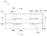
図1ないし図3に示すように装着補助器具101は、器具基体102に導線溝103を形成し、導線溝103に二つのヘッド挿入凹部104を形成している。
As shown in FIGS. 1 to 3, the mounting
器具基体102は直方体状のバルク部材である。片手で持つのに適当な寸法、例えば90mm(L)×40mm(W)×20mm(H)程度の大きさに形成されている。材質としては、木、樹脂、金属など各種のものを用いて器具基体102とすることができる。
The
導線溝103は接続作業の作業対象となる導線、本実施の形態ではリード線32と一次配線41とを真直ぐに収容することができる溝である。溝であるが故に底面105と相対面する一対の側壁106とからなる。導線溝103の幅を規定する一対の側壁106の間の間隔は、接続対象となる導線の太さに合わせた間隔に形成されている。
The
ヘッド挿入凹部104は、使用する蓄力コネクタ51のボルト52をヘッド54の側から挿入させる窪みである。ヘッド挿入凹部104はその底面を導線溝103の底面105と共用している。ヘッド挿入凹部104の一対の側壁については二種類の幅に形成されている。入口側では幅が広く形成され、奥側ではそれよりも幅が狭く形成されている。
The
ヘッド挿入凹部104の側壁のうち幅が狭く形成されている奥側の部分は回転規制壁104aである。一対の回転規制壁104aは、ボルト52が有するU溝56が導線溝103に向く角度でヘッド54を位置規制し、これによってボルト52を回り止めする間隔に形成されている。ボルト52のヘッド54は平べったい形状に形成されており、ネジ55の方向から見るとネジ55の部分よりも幅が広く(図11(a)参照)、U溝56の方向から見るとネジ55の部分よりも幅が狭い(図11(b)参照)。そこでネジ55の方向から見てヘッド54の平べったくなっている部分を一対の回転規制壁104aで両側から位置規制すれば、ヘッド54の回転を規制することができるわけである。このときU溝56は導線溝103に対面する。また一対の回転規制壁104aの対向間隔は、位置規制するヘッド54の部分よりも僅かに広く形成され、ヘッド54を挟んで持つことがないように設定されている。
Of the side wall of the
ヘッド挿入凹部104の側壁のうち幅が広く形成されている入口側の部分は入口壁104bである。一対の入口壁104bは、U溝56の方向から見てヘッド54よりも幅が広くなったボルト52のネジ55の部分の直径よりも僅かに対向間隔が広く形成され、このネジ55の部分を位置付ける。
Of the side wall of the
図4に装着補助器具101における各部の寸法を示す。図4中、左側は導線(リード線32及び一次配線41)の先端を位置付ける先端側、右側は導線の被覆部32a及び41aを位置付ける根元側となっている。図4に示すように、二つのヘッド挿入凹部104の長さと、二つのヘッド挿入凹部104の間の離間間隔(A区間)と、装着補助器具101の先端側に位置する導線溝103の端部から先端側のヘッド挿入凹部104までの距離(B区間)とはいずれも20mmに形成されている。装着補助器具101の根元側に位置する導線溝103の端部と根元側のヘッド挿入凹部104との間の距離(C区間)は10mmである。このような寸法関係は、図13に例示した寸法管理規定に沿ったものである。
FIG. 4 shows the dimensions of each part of the mounting
つまり図13に例示した寸法間規定では、二つの蓄力コネクタ51の間の間隔を20mm、導線先端と先端側の蓄力コネクタ51との間の距離を20mm、被覆部32a及び41aの端部と根元側のヘッド54との間の距離を10mmに定めている。そこで装着補助器具101は、A区間によって二つの蓄力コネクタ51の間の間隔が20mmになるようにし、B区間によって導線先端と先端側の蓄力コネクタ51との間の距離が20mmになるようにし、C区間によって被覆部32a及び41aの端部と根元側のヘッド54との間の距離が10mmになるようにしているわけである。
In other words, in the inter-dimensional regulation illustrated in FIG. 13, the distance between the two
したがって装着補助器具101の導線溝103は、その両端部を寸法管理するに際しての目印として使用できることが分かる。つまり装着補助器具101の先端側に位置する導線溝103の端部は、二本の導線の先端部を予め決められた規定の位置に位置合わせする目印として使用することができる。ここではこれを第1の目印151と呼ぶ。また装着補助器具101の根元側に位置する導線溝103の端部は、二本の導線の被覆部32a及び41aの端部を予め決められた規定の位置に位置合わせする目印として使用することができる。ここではこれを第2の目印152と呼ぶ。
Therefore, it can be seen that the
(2)第2の実施の形態
図5ないし図7に基づいて第2の実施の形態を説明する。第1の実施の形態と同一部分は同一符号で示し説明も省略する。
(2) Second Embodiment A second embodiment will be described with reference to FIGS. The same parts as those of the first embodiment are denoted by the same reference numerals, and description thereof is also omitted.
本実施の形態の装着補助器具101は、ヘッド挿入凹部104内の入口壁104bに弾性部材111を取り付けている。弾性部材111は例えばスポンジやゴムなどの柔軟性と弾力性とを兼ね備えた部材であり、例えば接着などの手法で入口壁104bに取り付けられている。先に説明したように、一対の入口壁104bの間の対向間隔はボルト52のネジ55の部分の直径よりも僅かに広く形成されている。これに対して一対の入口壁104bに取り付けられた一対の弾性部材111は、その対向間隔をネジ55の部分の直径よりも僅かに狭く形成している。これによって弾性部材111は、ヘッド挿入凹部104に挿入されたボルト52を弾性変形によって柔らかく保持する仮保持部112として機能する。
In the mounting assisting
2.蓄力コネクタを用いた導線接続方法
図8(a)〜(d)及び図9に基づいて、二つの蓄力コネクタ51を用いて変成器31のリード線32と一次配線41とを電気的機械的に接続する導線接続方法について説明する。第1及び第2の実施の形態と同一部分は同一符号で示し説明も省略する。本実施の形態の方法は第1の工程から第4の工程によって成し遂げられる。
2. Conductive wire connection method using power storage connector Based on FIGS. 8A to 8D and FIG. 9, the
(1)第1の工程
図8(a)に示すように、装着補助器具101に二つの蓄力コネクタ51のボルト52をそれぞれセットする。つまりヘッド挿入凹部104にヘッド54の側からボルト52を挿入する。
(1) 1st process As shown to Fig.8 (a), the
(2)第2の工程
図8(a)に示すように、ヘッド挿入凹部104の奥に設けられている一対の回転規制壁104aの間にヘッド54を嵌め込む。これによって装着補助器具101へのボルト52のセットが完了する。
(2) Second Step As shown in FIG. 8A, the
(3)第2のサブ工程
このとき第2の実施の形態の装着補助器具101を用いたならば、一対の回転規制壁104aの間にヘッド54を嵌め込むことによって、ボルト52のネジ55の部分が仮保持部112に仮保持される(第2のサブ工程)。つまりネジ55の部分は入口壁104bに取り付けられた一対の弾性部材111を弾性変形させ、これらの弾性部材111にボルト52の保持機能を生じさせるわけである。これによって装着補助器具101にボルト52が仮保持され、以後の作業がし易くなる。
(3) Second sub-step At this time, if the mounting
(4)第3の工程
第2の工程が完了すると、ボルト52のU溝56が導線溝103の方向を向く。
そこで図8(b)に示すように、変成器31のリード線32をU溝56と導線溝103とに差し込む。このときに注意すべきことは装着補助器具101の向きである。リード線32の先端をB区間の側、被覆部32aがある根元側をC区間の側に向けてリード線32をセットする(図4参照)。
続いて図8(c)に示すように、一次配線41もU溝56と導線溝103とに差し込む。
(4) Third Step When the second step is completed, the
Therefore, as shown in FIG. 8B, the
Subsequently, as shown in FIG. 8C, the
(5)第3のサブ工程
このような第3の工程に際しては、リード線32と一次配線41との先端部分を揃え、揃えた先端部を導線溝103の先端側端部である第1の目印151の位置に揃える。このときもしもリード線32と一次配線41との被覆部32a及び41aが正しい長さに剥かれているならば、被覆部32a及び41aの端部が導線溝103の根元側端部である第2の目印152の位置に揃うことになる。そうならない場合には、リード線32と一次配線41との被覆部32a及び41aを剥き直し、リード線32及び一次配線41の先端部が第1の目印151に位置合わせされると共に被覆部32a及び41aの端部が第2の目印152に位置合わせされるように調整する。
(5) Third Sub-Step In such a third step, the leading end portions of the
(6)第4の工程
図8(d)に示すように、第3の工程が完了したら、ボルト52のU溝56に蓄力座金PBを差し込みながらネジ55にナット53を螺合させる。そしてモンキーレンチやスパナなどを用いてナット53を締め込む。これによって蓄力座金PBの加圧体58がU溝56に差し込まれたリード線32と一次配線41とを圧縮して接続する。
(6) Fourth Step As shown in FIG. 8D, when the third step is completed, the
こうしてリード線32と一次配線41とが接続されたならば、蓄力コネクタ51から装着補助器具101を取り外す。この際、一対の回転規制壁104aがヘッド54を挟んで持つことがないため、装着補助器具101を蓄力コネクタ51から容易に脱落させることができる。また第2の実施の形態の装着補助器具101を用いた場合には仮保持部112がボルト52を仮保持しているが、これは一対の弾性部材111の弾性変形による柔らかな保持に過ぎないため、装着補助器具101の円滑な脱落に支障を与えることがない。
When the
蓄力コネクタ51から装着補助器具101を取り外した後、二つの蓄力コネクタ51による接続部分に高圧用端子カバー61を被せることで、すべての作業が完了する。
After removing the mounting
3.効果
以上説明したように本実施の形態によれば、蓄力コネクタ51の装着補助器具101を片手で持つだけで、二本の導線(リード線32、一次配線41)の接続に必要な個数の蓄力コネクタ51のボルト52が規定の間隔に配列されてしかも回り止めされた状態に維持される。このため劣悪な作業環境においても、装着補助器具101にセットされたボルト52のU溝56に導線を差し込んでナット53で締め付ける作業の作業性を良好にすることができる。その結果、作業効率の向上、作業員に与えるストレスの減少、それに作業品質の向上を図ることができる。
3. Effects As described above, according to the present embodiment, the number of auxiliary wires 101 (
本実施の形態では、二本の導線(リード線32、一次配線41)の先端部を予め決められた規定の位置に位置合わせする第1の目印151を設けておき、第3の工程において第1の目印151に二本の導線の先端部を位置合わせしている(第3のサブ工程)。これによって規定の管理寸法の通りに先端側の蓄力コネクタ51から導線先端までの距離を容易に距離出しすることができ、作業性をより一層の良好にすることができる。
In the present embodiment, a
この場合、第1の目印151として導線溝103の端部を用いているので、視覚的にも触覚的には第1の目印151を確認し易くすることができ、作業性が向上する。しかも第1の目印151のための特別な構造やマーキングが不要となり、装着補助器具101の構造の簡略化、その製造の容易化を図ることもできる。
In this case, since the end of the
本実施の形態ではまた、二本の導線(リード線32、一次配線41)の被覆部32a及び41aの端部を予め決められた規定の位置に位置合わせする第2の目印152を設けておき、第3の工程において第2の目印152に二本の導線の被覆部32a及び41aの端部を位置合わせしている(第3のサブ工程)。これによって規定の管理寸法の通りに二本の導線の被覆部32a及び41aの端部から根元側の蓄力コネクタ51までの距離を容易に距離出しすることができ、作業性をより一層の良好にすることができる。
In the present embodiment, a
この場合、第2の目印152として導線溝103の端部を用いれば、視覚的にも触覚的には第2の目印152を確認し易くすることができ、作業性が向上する。しかも第2の目印152のための特別な構造やマーキングが不要となり、装着補助器具101の構造の簡略化、その製造の容易化を図ることもできる。
In this case, if the end portion of the
第2の実施の形態ではさらに、ヘッド挿入凹部104に仮保持部112を設け、ヘッド挿入凹部104に挿入された蓄力コネクタ51のボルト52を仮保持部112の弾性変形によって保持するようにした。これによりボルト52が仮保持される。このため装着補助器具101をひっくり返したり多少乱暴に扱ったりしても、あるいは装着補助器具101にセットしたボルト52が接続前の一次配線41などにぶつかったりしても、ボルト52が装着補助器具101から脱落する可能性を格段に低くすることができる。劣悪な作業環境の中では、このようなボルト52の脱落防止策は極めて有効に機能することであろう。
In the second embodiment, a
4.変形例
実施に際しては各種の変形や変更が可能である。
例えば器具基体102の端部から端部に導線溝103を貫通させることなく、第1の目印151の部分において導線溝103を行き止まりの形状に形成しても良い。この場合には装着補助器具101にセットされたボルト52のU溝56に導線(リード線32、一次配線41)を差し込むに際して、導線の先端部を導線溝103の終端に突き当てれるだけで導線の位置決めを行うことができる。
4). Various modifications and changes can be made in implementation.
For example, the
32 リード線(導線)
41 一次配線(導線)
51 蓄力コネクタ
52 ボルト
53 ナット
54 ヘッド
56 U溝
101 装着補助器具
103 導線溝
104 ヘッド挿入凹部
104a 回転規制壁
112 仮保持部
151 第1の目印
152 第2の目印
PB 蓄力座金
32 Lead wire
41 Primary wiring (conductor)
51
Claims (12)
ことを特徴とする請求項1に記載の蓄力コネクタの装着補助器具。 A first position where the distal ends of the two conductors are aligned with a predetermined specified position that maintains a predetermined distance between the distal end portion and the power storage connector on the distal end side . With landmarks,
The mounting assisting device for a power storage connector according to claim 1.
ことを特徴とする請求項1ないし3のいずれか一に記載の蓄力コネクタの装着補助器具。 Position the end portions of the two conducting wires at predetermined predetermined positions that maintain the distance between the end portions of the covering portions and the power storage connector on the base side at a predetermined predetermined distance. With a second landmark to match,
A mounting assisting device for a power storage connector according to any one of claims 1 to 3.
ことを特徴とする請求項7に記載の蓄力コネクタを用いた導線接続方法。 In the third step, a predetermined specified distance is maintained that maintains the distance between the distal end portion of the two conductors and the energy storage connector on the distal end side at a predetermined specified distance . A third sub-step of aligning the tip portions of the two conductors with a first mark that aligns with the position;
A conductive wire connection method using the power storage connector according to claim 7.
ことを特徴とする請求項7ないし9のいずれか一に記載の蓄力コネクタを用いた導線接続方法。 In the third step, the covering end portions of the two conductive wires are preliminarily determined to maintain a distance between the covering portion end portion and the root-side energy storage connector at a predetermined specified distance. A third sub-step of aligning the end portions of the covering portions of the two conductors with a second mark that aligns with a specified position,
A conductive wire connecting method using the power storage connector according to any one of claims 7 to 9.
Priority Applications (1)
| Application Number | Priority Date | Filing Date | Title |
|---|---|---|---|
| JP2012222002A JP5583732B2 (en) | 2012-10-04 | 2012-10-04 | Auxiliary attachment device for accumulator connector and method for connecting conductor using accumulator connector |
Applications Claiming Priority (1)
| Application Number | Priority Date | Filing Date | Title |
|---|---|---|---|
| JP2012222002A JP5583732B2 (en) | 2012-10-04 | 2012-10-04 | Auxiliary attachment device for accumulator connector and method for connecting conductor using accumulator connector |
Publications (2)
| Publication Number | Publication Date |
|---|---|
| JP2014075267A JP2014075267A (en) | 2014-04-24 |
| JP5583732B2 true JP5583732B2 (en) | 2014-09-03 |
Family
ID=50749285
Family Applications (1)
| Application Number | Title | Priority Date | Filing Date |
|---|---|---|---|
| JP2012222002A Expired - Fee Related JP5583732B2 (en) | 2012-10-04 | 2012-10-04 | Auxiliary attachment device for accumulator connector and method for connecting conductor using accumulator connector |
Country Status (1)
| Country | Link |
|---|---|
| JP (1) | JP5583732B2 (en) |
Families Citing this family (1)
| Publication number | Priority date | Publication date | Assignee | Title |
|---|---|---|---|---|
| CN110797671A (en) * | 2019-11-05 | 2020-02-14 | 浙江永泰隆电子股份有限公司 | Connection structure of mutual inductor and wiring terminal button, manufacturing method thereof and instrument thereof |
Family Cites Families (3)
| Publication number | Priority date | Publication date | Assignee | Title |
|---|---|---|---|---|
| JPS5846586A (en) * | 1981-09-16 | 1983-03-18 | 東京電力株式会社 | Bolt type connector tool |
| JPH0731022A (en) * | 1993-05-12 | 1995-01-31 | Tohoku Electric Power Co Inc | Attaching tool for tightening connector of manipulator |
| JP2011243359A (en) * | 2010-05-17 | 2011-12-01 | Chugoku Electric Power Co Inc:The | Force storing connector unit |
-
2012
- 2012-10-04 JP JP2012222002A patent/JP5583732B2/en not_active Expired - Fee Related
Also Published As
| Publication number | Publication date |
|---|---|
| JP2014075267A (en) | 2014-04-24 |
Similar Documents
| Publication | Publication Date | Title |
|---|---|---|
| US10855005B2 (en) | Method and apparatus for locking assemblies | |
| US20160226158A1 (en) | Assembly and method for electrical splice connection of cables | |
| US8517776B1 (en) | Ground clamp for use with ball stud ground conductors | |
| KR20180129622A (en) | Bindless cover | |
| JP3016117U (en) | Electrical connector with strain relief | |
| KR101178898B1 (en) | A grounding device having a single fastening screw | |
| JP5274693B1 (en) | Power cable connector | |
| JP2013257975A (en) | Assembly structure of earth terminal | |
| JP5583732B2 (en) | Auxiliary attachment device for accumulator connector and method for connecting conductor using accumulator connector | |
| ITRM910386A1 (en) | BATTERY CABLE CONNECTOR | |
| CN204012078U (en) | The multi-functional grounding wire device of using | |
| JP2002134185A (en) | Connector | |
| JP2011243359A (en) | Force storing connector unit | |
| CN107457722A (en) | A kind of multi-functional cutting pliers | |
| JP3590885B2 (en) | Swivel joint | |
| JP5247372B2 (en) | Indirect hot wire work tool and indirect hot wire work tool | |
| US8495929B2 (en) | Lead connection and alignment tool | |
| JP3303618B2 (en) | Terminal device for electric equipment and method for fastening electric wires to electric equipment | |
| JP5172396B2 (en) | Power cable pooling eye | |
| CN209766660U (en) | Grounding wire | |
| JP7447062B2 (en) | double headed spanner | |
| US11616317B2 (en) | Angled power pin alignment and crimping fixture | |
| CN207841153U (en) | Cable fixing head locking tool | |
| JP3106339U (en) | Posture correction wrench for cable side terminal | |
| US10014626B1 (en) | Compression connector for terminating grounding electrodes |
Legal Events
| Date | Code | Title | Description |
|---|---|---|---|
| A131 | Notification of reasons for refusal |
Free format text: JAPANESE INTERMEDIATE CODE: A131 Effective date: 20140225 |
|
| A521 | Request for written amendment filed |
Free format text: JAPANESE INTERMEDIATE CODE: A523 Effective date: 20140414 |
|
| TRDD | Decision of grant or rejection written | ||
| A01 | Written decision to grant a patent or to grant a registration (utility model) |
Free format text: JAPANESE INTERMEDIATE CODE: A01 Effective date: 20140709 |
|
| A61 | First payment of annual fees (during grant procedure) |
Free format text: JAPANESE INTERMEDIATE CODE: A61 Effective date: 20140716 |
|
| R150 | Certificate of patent or registration of utility model |
Ref document number: 5583732 Country of ref document: JP Free format text: JAPANESE INTERMEDIATE CODE: R150 |
|
| R250 | Receipt of annual fees |
Free format text: JAPANESE INTERMEDIATE CODE: R250 |
|
| LAPS | Cancellation because of no payment of annual fees |