JP5580286B2 - Two-stage cooling system - Google Patents
Two-stage cooling system Download PDFInfo
- Publication number
- JP5580286B2 JP5580286B2 JP2011500971A JP2011500971A JP5580286B2 JP 5580286 B2 JP5580286 B2 JP 5580286B2 JP 2011500971 A JP2011500971 A JP 2011500971A JP 2011500971 A JP2011500971 A JP 2011500971A JP 5580286 B2 JP5580286 B2 JP 5580286B2
- Authority
- JP
- Japan
- Prior art keywords
- exhaust
- cooling system
- housing
- cabinet
- temperature
- Prior art date
- Legal status (The legal status is an assumption and is not a legal conclusion. Google has not performed a legal analysis and makes no representation as to the accuracy of the status listed.)
- Active
Links
- 238000001816 cooling Methods 0.000 title claims description 118
- 238000013016 damping Methods 0.000 claims description 28
- 239000004033 plastic Substances 0.000 claims description 17
- 229920003023 plastic Polymers 0.000 claims description 17
- 230000003584 silencer Effects 0.000 claims description 16
- 239000000428 dust Substances 0.000 claims description 2
- 239000007788 liquid Substances 0.000 claims description 2
- 230000002238 attenuated effect Effects 0.000 claims 1
- 239000007789 gas Substances 0.000 description 80
- 238000012546 transfer Methods 0.000 description 30
- 239000006260 foam Substances 0.000 description 12
- 229920001971 elastomer Polymers 0.000 description 6
- 125000000391 vinyl group Chemical group [H]C([*])=C([H])[H] 0.000 description 3
- 229920002554 vinyl polymer Polymers 0.000 description 3
- 230000008901 benefit Effects 0.000 description 2
- 230000006835 compression Effects 0.000 description 2
- 238000007906 compression Methods 0.000 description 2
- 230000000694 effects Effects 0.000 description 2
- 239000012530 fluid Substances 0.000 description 2
- 238000000034 method Methods 0.000 description 2
- 238000009423 ventilation Methods 0.000 description 2
- 230000003213 activating effect Effects 0.000 description 1
- 230000002411 adverse Effects 0.000 description 1
- 238000009529 body temperature measurement Methods 0.000 description 1
- 239000006227 byproduct Substances 0.000 description 1
- 238000004891 communication Methods 0.000 description 1
- 238000010276 construction Methods 0.000 description 1
- 239000000356 contaminant Substances 0.000 description 1
- 239000000112 cooling gas Substances 0.000 description 1
- 230000007423 decrease Effects 0.000 description 1
- 239000000806 elastomer Substances 0.000 description 1
- 239000000463 material Substances 0.000 description 1
- 238000012986 modification Methods 0.000 description 1
- 230000004048 modification Effects 0.000 description 1
- 239000004417 polycarbonate Substances 0.000 description 1
- 229920000515 polycarbonate Polymers 0.000 description 1
- 239000011148 porous material Substances 0.000 description 1
- 238000007789 sealing Methods 0.000 description 1
Images


Classifications
-
- F—MECHANICAL ENGINEERING; LIGHTING; HEATING; WEAPONS; BLASTING
- F25—REFRIGERATION OR COOLING; COMBINED HEATING AND REFRIGERATION SYSTEMS; HEAT PUMP SYSTEMS; MANUFACTURE OR STORAGE OF ICE; LIQUEFACTION SOLIDIFICATION OF GASES
- F25B—REFRIGERATION MACHINES, PLANTS OR SYSTEMS; COMBINED HEATING AND REFRIGERATION SYSTEMS; HEAT PUMP SYSTEMS
- F25B9/00—Compression machines, plants or systems, in which the refrigerant is air or other gas of low boiling point
- F25B9/02—Compression machines, plants or systems, in which the refrigerant is air or other gas of low boiling point using Joule-Thompson effect; using vortex effect
- F25B9/04—Compression machines, plants or systems, in which the refrigerant is air or other gas of low boiling point using Joule-Thompson effect; using vortex effect using vortex effect
-
- F—MECHANICAL ENGINEERING; LIGHTING; HEATING; WEAPONS; BLASTING
- F25—REFRIGERATION OR COOLING; COMBINED HEATING AND REFRIGERATION SYSTEMS; HEAT PUMP SYSTEMS; MANUFACTURE OR STORAGE OF ICE; LIQUEFACTION SOLIDIFICATION OF GASES
- F25B—REFRIGERATION MACHINES, PLANTS OR SYSTEMS; COMBINED HEATING AND REFRIGERATION SYSTEMS; HEAT PUMP SYSTEMS
- F25B2500/00—Problems to be solved
- F25B2500/12—Sound
Description
本発明は、概して、筐体の内部を冷却する2段冷却システムに関する。 The present invention generally relates to a two-stage cooling system that cools the interior of a housing.
関連米国出願データ
本出願は、米国特許法第119条(e)に基づき、2008年3月21日に出願された米国特許仮出願第61/038,528号の出願日の利益を主張し、この仮出願の全体は参照により本出願に援用される。
Relevant US Application Data This application claims the benefit of the filing date of US Provisional Patent Application No. 61 / 038,528, filed on March 21, 2008, under 35 USC 119 (e). The entire application is incorporated herein by reference.
周囲環境に対して密閉され、実質的に密閉され、或いは密閉されていない様々な筐体が冷却される。典型的に、筐体は、室温や周囲温度よりも高く上昇した温度によって悪影響を受けるおそれのある種々の部品を収容する。電気機器を内包する筐体の場合、筐体内の温度が上昇することによって、部品が損傷したり、或いは、安全上の問題、例えば火災が生じうる。これらの筐体の多く、とりわけ実質的にまたは完全に密閉されているものは、換気が容易でない。 Various enclosures that are sealed to the surrounding environment, substantially sealed, or not sealed are cooled. Typically, the housing contains various components that can be adversely affected by elevated temperatures above room temperature or ambient temperature. In the case of a housing containing an electric device, the temperature in the housing rises, so that parts may be damaged or a safety problem such as a fire may occur. Many of these enclosures, especially those that are substantially or completely sealed, are not easily ventilated.
米国特許第3,654,768号「ボルテックスチューブ冷却システム」(以下、特許文献1とする)を本願と一体をなすものとして参照する。特許文献1は、密閉された筐体、実質的に密閉された筐体または密閉されていない筐体といった、様々なタイプの筐体に個々に適合する冷却システムを開示している。特許文献1に開示されるシステムは、ボルテックスチューブ冷却システムであり、ボルテックスチューブへ供給される圧縮空気の流れを制御する弁の作動を操作し、筐体内部の温度制御を行う機械式サーモスタットを有する。特許文献1に記載される実施例は、比較的小型のサーモスタット制御式冷却システムであり、従来の「フレオン型」の空調装置と比べると、取付けが簡単で手入れをあまり必要としない。然しながら、特許文献1に記載されるシステムは、高い騒音レベルを生じる冷却システムである。特に、ボルテックスチューブ内の高速回転空気によって生じる騒音は、人によっては不快となり得る。このような騒音は、筐体のオペレータ、または筐体の近くにいる人々に不快感を与えたり、苛立たせたり、或いは苦痛をもたらすことさえある。 U.S. Pat. No. 3,654,768 "Vortex Tube Cooling System" (hereinafter referred to as Patent Document 1) is referred to as an integral part of this application. U.S. Pat. No. 6,057,059 discloses a cooling system that is individually adapted to various types of enclosures, such as a sealed enclosure, a substantially enclosed enclosure, or an unsealed enclosure. The system disclosed in Patent Document 1 is a vortex tube cooling system, which has a mechanical thermostat that operates a valve that controls the flow of compressed air supplied to the vortex tube and controls the temperature inside the housing. . The embodiment described in Patent Document 1 is a relatively small thermostat-controlled cooling system, which is easier to install and requires less care than a conventional “Freon type” air conditioner. However, the system described in Patent Document 1 is a cooling system that generates a high noise level. In particular, noise generated by high-speed rotating air in the vortex tube can be uncomfortable for some people. Such noise can be uncomfortable, annoying or even painful to the operator of the enclosure, or to people near the enclosure.
ボルテックスチューブの騒音を最小限にしようとするこれまでの試みには、ボルテックスチューブの高温側端部および低温端に消音管を取付けることも含まれる。然しながら、消音管が実質的に低減される騒音レベルはわずかである。 Previous attempts to minimize vortex tube noise include attaching silencer tubes to the hot and cold ends of the vortex tube. However, the noise level at which the silencer is substantially reduced is small.
米国特許第7,461,513号「冷却システム」(以下、特許文献2とする)を本願と一体をなすものとして参照する。特許文献2は、取付けが簡単で騒音レベルが低い、小型の冷却システムを開示している。特許文献2に開示されるシステムは、冷却装置を1つしか有しないことから、システムの冷却能力は制限される。 Reference is made to US Pat. No. 7,461,513 “Cooling System” (hereinafter referred to as Patent Document 2) as an integral part of the present application. Patent Document 2 discloses a small cooling system that is easy to install and has a low noise level. Since the system disclosed in Patent Document 2 has only one cooling device, the cooling capacity of the system is limited.
米国特許第5,010,736号「筐体用冷却システム」(以下、特許文献3とする)は、二段階筐体冷却器を開示している。特許文献3に開示されるシステムは、2つの異なる種類の冷却方式を用いる。第一段階の冷却は、単純な空気対空気の熱交換により行い、第二段階の冷却は、ボルテックスチューブ冷却器により行う。特許文献3に記載されるシステムでは、第一段階の熱交換器は、決して停止することなく作動し続ける。この第一段階の冷却器は、熱交換器である(「積極的な」冷却装置ではない)ため、かかるシステムと共に使用される筐体内の温度は、周囲の温度状況よりも低温に冷却されることはない。 US Pat. No. 5,010,736 “Cooling System for Housing” (hereinafter referred to as Patent Document 3) discloses a two-stage housing cooler. The system disclosed in Patent Document 3 uses two different types of cooling systems. The first stage cooling is performed by simple air-to-air heat exchange, and the second stage cooling is performed by a vortex tube cooler. In the system described in Patent Document 3, the first-stage heat exchanger continues to operate without stopping. This first stage cooler is a heat exchanger (not an “aggressive” cooling device), so the temperature in the enclosure used with such a system is cooled to a lower temperature than the ambient temperature conditions. There is nothing.
従って、実質的な冷却能力を有し、また取付けが簡単で騒音レベルが低い冷却システムの必要性が存在する。 Accordingly, there is a need for a cooling system that has substantial cooling capacity, is easy to install, and has a low noise level.
更に、低熱負荷時における圧縮空気の消費量を低減することができる冷却システムが必要とされ、また望まれている。 Furthermore, there is a need and desire for a cooling system that can reduce the consumption of compressed air during low heat loads.
本発明の原理に基づく2段冷却システムは、電気筐体のような筐体に冷気を供給する。本発明の特定の実施形態は、筐体の内部を冷却する冷却システムを提供し、該冷却システムは、排気室を画成するキャビネットと、排気室内の第1の高温管路およびキャビネットから外側に延びる第1の低温ガス吐出管路を含む第1のボルテックスチューブと、排気室内の第2の高温管路およびキャビネットから外側に延びる第2の低温ガス吐出管路を含む第2のボルテックスチューブとを有する。第1と第2の低温ガス吐出管路から(空気等の)低温ガスが筐体内部に吐出される。 A two-stage cooling system based on the principles of the present invention supplies cool air to a housing such as an electrical housing. Certain embodiments of the present invention provide a cooling system for cooling the interior of a housing, the cooling system being external to the cabinet defining the exhaust chamber, the first hot line in the exhaust chamber and the cabinet. A first vortex tube including a first cold gas discharge line extending; and a second vortex tube including a second high temperature gas discharge line extending outwardly from the second high temperature line and the cabinet in the exhaust chamber. Have. Low temperature gas (such as air) is discharged into the housing from the first and second low temperature gas discharge lines.
第1のサーモスタットを、第1のボルテックスチューブに作動可能に取付けて、キャビネットから外側に延在させてもよい。同様に、第2のサーモスタットを、第2のボルテックスチューブに作動可能に取付けて、キャビネットから外側に延在させてもよい。第1と第2のサーモスタットの各々は、筐体の内部に配置されるように構成してもよい。キャビネット内のボルテックス冷却装置の各々は独立した機械式サーモスタットにより制御されるため、熱負荷(筐体内の温度)が低い場合、一方の冷却装置のみが作動し、そして熱負荷が上昇したら、第2のボルテックス冷却装置を作動させるように、これらを調整することができる。これにより、低熱負荷時における圧縮空気の消費量を低減することが可能となる。 A first thermostat may be operably attached to the first vortex tube and extend outward from the cabinet. Similarly, a second thermostat may be operably attached to the second vortex tube and extend outward from the cabinet. Each of the first and second thermostats may be configured to be disposed inside the housing. Each of the vortex cooling devices in the cabinet is controlled by an independent mechanical thermostat, so if the heat load (temperature in the enclosure) is low, only one of the cooling devices will work and if the heat load rises, the second These can be adjusted to activate the vortex cooling system. Thereby, it becomes possible to reduce the consumption of compressed air at the time of low heat load.
1または複数の多孔質プラスチック消音管を、第1の高温管路の出口および第2の高温管路の出口に接続してもよい。第1の高温管路および第2の高温管路から排気される排気ガスを、1または複数の多孔質プラスチック消音管に送り、多孔質プラスチック消音管を通過させてもよい。 One or more porous plastic silencers may be connected to the outlet of the first hot line and the outlet of the second hot line. The exhaust gas exhausted from the first high-temperature pipe line and the second high-temperature pipe line may be sent to one or a plurality of porous plastic silencer pipes and allowed to pass through the porous plastic silencer pipe.
1または複数の逆止弁を、第2の高温管路に作動可能に取付けて、第1の高温管路から第2の高温管路内への高温排気の逆流を防いでもよい。 One or more check valves may be operatively attached to the second hot line to prevent back flow of hot exhaust from the first hot line into the second hot line.
減衰スリーブを、第1と第2の高温管路の各々の少なくとも一部の周囲に取付けてもよい。減衰スリーブはゴムから形成することができ、各ボルテックスチューブによる騒音を吸収、減衰または低減する。 A damping sleeve may be attached around at least a portion of each of the first and second hot conduits. The damping sleeve can be made of rubber and absorbs, attenuates or reduces the noise caused by each vortex tube.
キャビネットは、後壁および側壁と一体的に形成される底部を含んでもよい。上壁を後壁および側壁と一体的に形成し、これらで排気室を画成してもよい。排気室を覆うカバーを設置することができ、また少なくとも1つの減衰シートを、底部、後壁、側壁および/または上壁の少なくとも一部に裏張りしてもよい。減衰シートは、第1と第2のボルテックスチューブによってもたらされる騒音を減衰する。更に、可撓性を有する減衰ロッドを排気室内に配置して、ボルテックスチューブによってもたらされる騒音を更に減衰するようにしてもよい。 The cabinet may include a bottom formed integrally with the rear wall and the side wall. The upper wall may be formed integrally with the rear wall and the side wall, and these may define the exhaust chamber. A cover covering the exhaust chamber may be installed and at least one damping sheet may be lined on at least a portion of the bottom, rear wall, side wall and / or top wall. The damping sheet attenuates the noise caused by the first and second vortex tubes. Furthermore, a flexible damping rod may be placed in the exhaust chamber to further attenuate the noise caused by the vortex tube.
また、本発明の特定の実施形態は、キャビネット内に固定され、筐体内部のガスが排気室内に排気される1または複数の排気管路が設けられる。1または複数の可撓性の開放端チューブを、(1または複数の)排気管路に取付けてもよい。可撓性の開放端チューブは、ガスが排気管路から可撓性チューブを経て排気されるように構成してもよい。 Also, certain embodiments of the present invention are provided with one or more exhaust conduits that are fixed in the cabinet and exhaust the gas inside the housing into the exhaust chamber. One or more flexible open end tubes may be attached to the exhaust line (s). The flexible open end tube may be configured such that gas is exhausted from the exhaust line through the flexible tube.
また、本発明の特定の形態では、キャビネットにはガスをキャビネット外に排気する排気口が形成されている。更に、シュラウドを、排気口を覆うようにキャビネットに取付けてもよい。シュラウドは排気通路を含んでもよく、排気口を通過した排気ガスがこの排気通路を通過できるように設計される。特に、シュラウドは、液体の浸入を防止する1または複数の内部バッフルを含んでもよい。更に、バッフルをキャビネットの内部に配置して、排気室を高温排気部と低温排気部とに隔離してもよい。 Moreover, in the specific form of this invention, the exhaust port which exhausts gas out of a cabinet is formed in the cabinet. Further, the shroud may be attached to the cabinet so as to cover the exhaust port. The shroud may include an exhaust passage, and is designed so that exhaust gas that has passed through the exhaust port can pass through the exhaust passage. In particular, the shroud may include one or more internal baffles that prevent liquid ingress. Further, a baffle may be disposed inside the cabinet to isolate the exhaust chamber into a high temperature exhaust part and a low temperature exhaust part.
1または複数の通気孔を、筐体の内部と空気源とに連通するように形成してもよい。通気孔は、空気を筐体に流入させるように機能し、筐体内部と外部環境との間の圧力差を維持する。かかる圧力差は、ボルテックスチューブが作動していない場合であっても、筐体内へのゴミの侵入を防止する。 One or a plurality of vent holes may be formed so as to communicate with the inside of the housing and the air source. The vent hole functions to allow air to flow into the housing, and maintains a pressure difference between the inside of the housing and the external environment. Such a pressure difference prevents dust from entering the housing even when the vortex tube is not operating.
添付図面を参照してする以下の詳細な説明から、本発明は一層に理解されるであろう。なお、添付図面において同一の部品は同一の参照番号にて指示されている。 The invention will be better understood from the following detailed description with reference to the accompanying drawings. In the accompanying drawings, the same parts are designated by the same reference numerals.
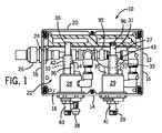
図1は、本発明の実施形態による2段冷却システム10の内部の正面斜視図である。冷却システム10はキャビネット12を含む。該キャビネットは、ポリカーボネートから形成することができ、側壁16および後壁18と共に一体的に形成される底部14を含む。側面16および後壁18は、また、上壁20と一体的に形成される。底部14、側壁16、後壁18および上壁20によって排気室22が画成される。排気室22は、着脱自在の正面カバー(図1に示さず)を底部14、側壁16および上壁20の縁部に固定することによって閉鎖される。
FIG. 1 is a front perspective view of the inside of a two-
ガス入口通路24が側壁16の一方に貫通、形成されている。ガス入口通路24は、ガス(空気等)圧縮システム(図1に示さず)のガス吐出管路(パイプ、ダクト等)26を受容、保持する。ガス入口通路24は、ねじ込み式または圧縮式継手によってガス吐出管路26を固定して保持する。ガス入口通路24は、以下に説明する第1と第2の主熱伝導ハウジング28、29に接続される。
A
排気口27が後壁18に貫通、形成されている。排気口27より、排気室22内の空気等のガスは冷却システム10の外に排気される。
An
第1の円筒形主熱伝導ハウジング28は、底部14に形成された開口部(図示せず)に種々の継手を介して固定、保持することができる。第1の円筒形主要ハウジング28は、例えば、前記開口部にねじ込み式に固定することができよう。或いは第1の円筒形主要ハウジング28は底部14に接合してもよい。第1の主熱伝導ハウジング28は排気室22内に突出し、第1のボルテックスチューブ30を支持する。該第1のボルテックスチューブは、第1の高温管路(パイプ、ダクト等)32と、キャビネット12の底部14を貫通して延びる第1の低温ガス吐出管路40とを含む。第1の主熱伝導ハウジング28は、また、2つの上方に延びる排気管路(パイプ、ダクト等)34、36を支持する。第1のサーモスタット38および第1の低温ガス吐出管路40が、第1の主熱伝導ハウジング28から底部14を貫通して延びている。第1の高温管路32は、第1のボルテックスチューブ30の一方の端部とすることができ、第1の低温ガス吐出管路40は、第1のボルテックスチューブ30の他方端部とすることができる。
The first cylindrical main
同様に、第2の円筒形主熱伝導ハウジング29は、底部14に形成された開口部(図示せず)に種々の継手を介して固定、保持することができる。第2の円筒形主要ハウジング29は、例えば、前記開口部にねじ込み式に固定することができる。或いは、第2の円筒形主要ハウジング29は底部14に接合してもよい。第2の主熱伝導ハウジング29は、排気室22内に突出し、第2のボルテックスチューブ31を支持する。第2のボルテックスチューブ31は、第2の高温管路(パイプ、ダクト等)33と、キャビネット12の底部14を貫通して延びる第2の低温ガス吐出管路41とを含む。第2の主熱伝導ハウジング29は、また、上方に延びる2本の排気管路(パイプ、ダクト等)35、37を支持する。第2のサーモスタット39および第2の低温ガス吐出管路41は、第2の主熱伝導ハウジング29から底部14を貫通して延びる。第2の高温管路33は、第2のボルテックスチューブ31の一方端部とすることができ、これに対し、第2の低温ガス吐出管路41は、第2のボルテックスチューブ31の他方の端部とすることができる。
Similarly, the second cylindrical main heat-conducting
第1の円筒形主熱伝導ハウジング28は、圧縮空気配管95を用いて第2の円筒形主熱伝導ハウジング29に連結される。圧縮空気入口配管95は、ガス入口通路24と連通している。
The first cylindrical main
第1と第2の主熱伝導ハウジング28、29の各々は、空気等の低温ガスを生成する。生成された低温ガスの各々は、第1と第2の低温ガス吐出管路40、41を介して冷却システム10の外に排気される。第1と第2のサーモスタット38、39の各々は、筐体(図示せず)内の温度を検知する。第1と第2の主熱伝導ハウジング28、29の各々は、第1と第2のサーモスタット38、39の温度測定値に基づいて低温空気を生成する。生成された低温空気の各々は、第1と第2の低温ガス吐出管路40、41を介して送り出される。
Each of the first and second main
第1と第2の主熱伝導ハウジング28、29の各々は、独立した第1と第2のサーモスタット38、39により制御されるため、第1と第2の主熱伝導ハウジング28、29は、熱負荷すなわち筐体内の温度が低い場合には第1の主熱伝導ハウジング28のみが作動するように、調整することができる。もし熱負荷が上昇したら、第2の主熱伝導ハウジング29を作動させる。或いは、第1と第2の主熱伝導ハウジング28、29は、熱負荷が低い場合には第2の主熱伝導ハウジング29のみを作動させ、そして熱負荷が上昇した場合には第1の主熱伝導ハウジング28を作動させることができるように、これらを調整可能である。この2段冷却システム10によって、低熱負荷時における圧縮空気の消費量を低減することが可能となる。以下は、2段冷却システム10の作動例である。
Since each of the first and second main
筐体内温度が上昇し、32.2°C(90°F)で第1の主熱伝導ハウジング28が作動する。
筐体内温度が上昇を続け、37.8°C(100°F)で第2の主熱伝導ハウジング29が作動する。
筐体内温度が下降し始め、32.2°C(90°F)で第2の主熱伝導ハウジング29が停止する。
筐体内温度が更に下降し、26.7°C(90°F)で第1の主熱伝導ハウジング28が停止する。
The temperature inside the housing rises and the first main
The temperature inside the housing continues to rise, and the second main
The temperature inside the housing starts to drop, and the second main
The temperature inside the casing further decreases, and the first main
2段冷却システム10は、特に電気筐体の冷却に適している。一段冷却システムの冷却能力が最高0.73kW(2500BTUH)であるのに対し、主熱伝導ハウジング28、29の内部に2つの冷却装置を備える2段冷却システム10の冷却能力ははるかに高く、例えば1.47kW(5000BTUH)である。
The two-
然しながら、この熱伝導プロセスの副生成物として、第1(および潜在的に第2)の主熱伝導ハウジング28(および29)は、また、排気室22内に空気等の加熱ガスを生成する。加熱ガスは排気口27から排気される。更に、システム10が2段式の構成を有しているので、第2のボルテックスチューブすなわち第二段階のボルテックスチューブ31の高温側端部に少なくとも1つの逆止弁96を設けることが好ましい。逆止弁96を備えない場合、第一段階の冷却のみが行われている場合に、第一段階の冷却装置すなわち第1のボルテックスチューブ30からの高温排気が、第二段階の冷却装置すなわち第2のボルテックスチューブ31の高温排気側から逆流して筐体内に流入し、その結果、第一段階の冷却装置すなわち第1のボルテックスチューブ30の冷却効果が低下または無効となる可能性がある。第二段階のボルテックスチューブ31の高温側端部の逆止弁96は、このような逆流を防止する。
However, as a by-product of this heat transfer process, the first (and potentially second) main heat transfer housing 28 (and 29) also generates a heated gas, such as air, in the
図2は、第二段階のボルテックスチューブ31の高温側端部に2つの逆止弁96を備えた2段冷却システム10を示す。
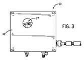
図3は、2段冷却システム10の背面斜視図である。図3に示すように、排気口27は、排気室22(図1に示す)内のガスを冷却システム10から排気するための通路を形成する。
FIG. 2 shows a two-
FIG. 3 is a rear perspective view of the two-
図4は、2段冷却システム10の底面斜視図である。図4に示すように、第1と第2の主熱伝導ハウジング28、29は底部14内に固定される。第1と第2のボルテックスチューブ30、31の各々の第1と第2のサーモスタット38、39および第1と第2の低温ガス吐出管路40、41が、主熱伝導ハウジング28、29から下方に突出する。排気口100が、第1の主熱伝導ハウジング28を貫通させて形成され、排気管路34(図1に示す)と連通する。同様に、排気口101が、第2の主熱伝導ハウジング29を貫通させて形成され、排気管路35(図1に示す)と連通する。同様に、排気口102が、第1の主熱伝導ハウジング28を貫通させ形成され、排気管路36(図1に示す)と連通する。同様に、排気口103が、第2の主熱伝導ハウジング29を貫通させて形成され、排気管路37(図1に示す)と連通する。排気口100、102によって、空気等のガスは、排気管路34、36へ、そして排気室22(図1に示す)の高温領域に流入し、最終的に排気口27(図1、2に示す)から冷却システム10の外に排気される。また、排気口101、103によって、空気等のガスが、排気管路35、37へ、そして排気室22の高温領域内に流入し、最終的に排気口27から冷却システム10の外に排気される。また、第1の主熱伝導ハウジング28を貫通させて、第1の通気孔104を形成することができる。該第1の通気孔によって、ガスは、第1の主熱伝導ハウジング28から冷却システム10外へ筐体内に排気される。同様に、第2の主熱伝導ハウジング29を貫通させて、第2の通気孔105を形成することができる。該第2の通気孔によって、ガスは、第2の主熱伝導ハウジング29から冷却システム10外へ筐体内に排気される。以下に説明するように、通気孔104、105は、筐体内部と外部環境との間の圧力差を維持し筐体内部を清浄に保つために用いることもできる。
FIG. 4 is a bottom perspective view of the two-
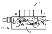
様々な技術を用いてボルテックスチューブ30、31の騒音レベルを低減することができる。例えば、図5は、2段冷却システム10の内部の上面斜視図であり、該2段冷却システムでは、第1のボルテックスチューブ30の高温側端部の出口と第2のボルテックスチューブ31の高温側端部の出口とに多孔質プラスチック消音管50が接続される。多孔質プラスチック消音管50は排気室22内に固定することができよう。各ボルテックスチューブ30、31から排気される高温排気は、共通の多孔質プラスチック消音管50を経由することも、或いは別個の消音管50を経由することもできる。消音管50は多孔質であるため、高温排気ガスは該消音管を通過して排気口27から排気される。
Various techniques can be used to reduce the noise level of the
図6は、2段冷却システム10の内部の側面斜視図である。第1の減衰スリーブ42が第1の高温管路32を覆うように配置されている。図1に示すように、第2の減衰スリーブ43は、同様に第2の高温管路33を覆うように配置される。ボルテックスチューブ30、31の高温管路32、33の各々は各減衰スリーブ42、43の内側に包囲される。該減衰スリーブは、各高温管路32、33の相当部分を取り囲むエラストラマーまたはゴムホースとすることができる。減衰スリーブ42、43は、高温管路32、33から伝わる高周波振動およびそれに伴う騒音を減衰することにより、ボルテックスチューブ30、31の内部に生じる騒音または同チューブによって生じる騒音を低減する。何れの場合でも、減衰スリーブ42、43を高温管路32、33の周囲に設けることでボルテックスチューブ30、31により生じる騒音量を減衰或いは低減することが分かっている。
FIG. 6 is a side perspective view of the inside of the two-
図7は、圧縮空気配管95を介して連結された2つのボルテックス冷却装置30、31の正面斜視図である。理解し易いように冷却システムの残りの部分は省略する。図7に示すように、中空可撓性の端部が開放したチューブ(開放端チューブ)44が排気管路35に取付けられ、中空可撓性の開放端チューブ46が排気管路37に取付けられる。チューブ44、46は、ビニール管とすることができる。排気管路35、37からのガスは、チューブ44、46内を通過し、チューブ44、46の開放端から排気室22の低温領域に排気される。特定の実施形態では、同様の中空可撓性の開放端チューブを、排気管路34、36の一方または双方に取付けてもよい。
FIG. 7 is a front perspective view of two
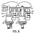
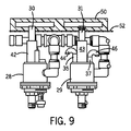
バッフル52をキャビネット12内に配置して、排気室22を高温排気部と低温排気部とに分割してもよい。図8は、2つのボルテックス冷却装置30、31に対するバッフル52の適切な配置を例示する。図9は、多孔質プラスチック消音管50と、2つのボルテックス冷却装置30、31との間におけるバッフル52の適切な配置を例示する。図6に更に例示するように、このような配置により、排気口27は高温排気部と低温排気部とに分割される。高温管路32、33を出た高温排気ガスは、多孔質プラスチック消音管50の外へ通過し、排気口27の高温排気部から冷却システム10の外に排気される。これに対し、排気管路34、35、36、37を出た低温排気ガスは、排気口27の低温排気部から冷却システム10の外に排気される。バッフル52は、排気室22を2つの独立した領域、すなわち高温排気領域54と低温排気領域56とに隔離するプラスチック、ゴム、ビニール等から形成することがでる。このようにして、排気室22内の高温ガスと低温ガスは、相互に分離される。バッフル52は、排気室22内における高温空気の流れと低温空気の流れとを相互に分離することで、高温排気ガスによって生じる圧力によって、低温空気の排気を阻害しないようにする。
The
図10は、キャビネット12内の所定位置に設けられた2つのボルテックス冷却装置30、31を示す。連続気泡発泡体シート60によって、排気室22内においてキャビネット12の後壁18の内面が被覆されている。また、排気室22内においてキャビネット12の底部14、側壁16および上壁20の内面を連続気泡発泡体で被覆してもよい。更に、キャビネット12のカバー(図示せず)の内面を連続気泡発泡体シートで被覆してもよい。連続気泡発泡体シート60および排気室22内の他の気泡発泡体は、冷却システム10がもたらす騒音を一層減衰する一方で、また排気ガスの流通を可能にする。排気室22内におけるキャビネット12の内面に加えて、或いは同内面の代わりに、キャビネット12の外面を連続気泡発泡体シートで被覆してもよい。また、シート60は、連続気泡発泡体に代えて、ゴム、プラスチック等の他の減衰材料とすることができる。
FIG. 10 shows two
図11に示すように、後壁18の外側を覆うようにシュラウド64を取付け、後壁18の大部分を被覆するようにできる。排気通路が、シュラウド64の内側と後壁18の外面との間に画成される。こうして、排気ガスは、排気口27を通して排気室22から排気することができる。排気ガスはその後、シュラウド64によって方向を変え、シュラウド64の下部の排気出口68を通過する。例えば、排気管路35、37から可撓性チューブ44、46を通過した比較的低温の排気ガスは、排気口27を通過し、排気出口68を通じて冷却システム10の外に排気されよう。同様に、高温管路32、33から多孔質プラスチック消音管50(図6に示す)を通過した高温排気ガスは、プラスチック管50の細孔を通り抜け、排気口27から冷却システム10の外に排気されよう。その後、高温排気ガスは、排気出口68を通じて冷却システム10外に排気されよう。
As shown in FIG. 11, a
図12は、シュラウド64内部を示した図である。シュラウド64は、取付フランジ部または縁部108を有する側壁106と、取付フランジ部または縁部112を有する頂壁110と、カバー114とを含む。側壁106、頂壁110およびカバー114によって排気室116が画成される。シュラウド64は、キャビネット12の背面(例えば図6、11に示す)に設置され。例えば、シュラウド64は、取付フランジ部108、112がキャビネット12の後壁に当接するように取付けられる。
FIG. 12 is a view showing the inside of the
一連のバッフル118が排気室116内に配置される。排気出口68は、下方バッフル118に近接する、シュラウド64の下部を貫通して形成される。バッフル118は、シュラウド64への湿気の浸入を防止する。4つのバッフル118が例示されているが、これより多いまたは少ないバッフルをシュラウド64に用いてもよい。
A series of
図13は、圧縮ガスフィルター70に接続された2段冷却システム10の正面斜視図である。圧縮ガスフィルター70は、吐出管路72を介して主熱伝導ハウジング28、29に供給される空気等の圧縮ガスを濾過する。他の構成では、吐出管路72は、主熱伝導ハウジング28、29に接続する対応する入口管路74に気密に固定するようにしてもよい。吐出管路72および入口管路74は、ガス入口通路24に隣接させて、例えば密封ねじ込み接続により相互に気密に固定することができる。こうして、空気等の圧縮ガスは、ガスフィルター70から吐出管路72を介して入口管路74に流入することができ、そして入口管路は、圧縮空気配管95を通り主熱伝導ハウジング28、29内に至る流体通路を形成する。サーモスタット38、39の何れか一方または双方が冷却を要求すると、高温管路32、33および低温ガス吐出管路40、41を含む、ボルテックスチューブ30、31の何れか一方または双方に圧縮ガスが流入し、これにより低温ガスが生成されて低温ガス吐出管路40、41へと送られる。このようにして、2段冷却システム10は、(1または複数の)ボルテックスチューブに圧縮空気を供給することによって冷却ガスを生成することができる。
FIG. 13 is a front perspective view of the two-
図13に示すように、圧縮空気を冷却システム10内に送り込む入口管路74をキャビネット12の低温排気部内に配置することで、パイプ50から排気される高温排気が、入口管路74を介して冷却システム10に送られる圧縮空気に近接しないようにする。
As shown in FIG. 13, by arranging an inlet pipe 74 for sending compressed air into the
図14は複数の可撓性減衰部材76を備えた冷却システムの内部の正面斜視図である。可撓性減衰部材76は、可撓性を有する連続気泡発泡体ロッドとすることができる。各ロッドの直径は、約50.8mm(2inch)とすることができる。図14に示すように、2つの可撓性減衰部材76が、排気室22の高温排気領域54内に折曲げた状態で詰込まれ、更に、より多くの減衰部材76が、低温空気領域56内に折曲げた状態で詰込まれる。更なる減衰部材76を、排気室22内に配置してもよい。概して、連続気泡発泡体が可撓性ロッド状減衰部材76の形状であるか、或いは(図10に示される連続気泡発泡体シート60のような)シート形状であるかを問わず、連続気泡発泡体に排気室22のかなりの部分を占有させるようにできる。例えば、連続気泡発泡体が、排気室22内の空間の約90%を占有してもよい。減衰部材76は、冷却システム10内における更なる騒音減衰性を有すると同時に、同減衰部材内に排気ガスを流通させることが可能である。また、減衰部材76は、多孔質ゴム、プラスチック等から形成することができる。
FIG. 14 is a front perspective view of the inside of the cooling system including a plurality of flexible damping
図15、16の各々は、筐体80に接続された2段冷却システム10の正面図および側面図である。キャビネット12は、底部14が筐体80の頂面82によって支持されるように、筐体80の頂部に取付けられる。2つの開口部84、85が筐体80の頂面82を貫通して形成され、各主熱伝導ハウジング28、29の下部は、各開口部84、85内に気密に固定される。サーモスタット38、39および低温ガス吐出管路40、41は、筐体80の内室86内に突出する。排気口100、101、102、103(図4に示す)および通気孔104、105(図4に示す)もまた内室86に開口する。
15 and 16 are a front view and a side view of the two-
空気等のガスが、圧縮ガスシステムおよび空気フィルター70を介して主熱伝導ハウジング28、29に供給される。そして、主熱伝導ハウジング28、29は、(高温パイプおよび低温ガス吐出管路を含む)ボルテックスチューブによって低温ガスを生成する。低温ガス吐出管路40、41の各々の先端は、低温ガス吐出管路40、41から消音管90、91までの流体通路を提供する可撓性チューブ88、89の一端に接続される。複数の通路94、95を有する密封チューブ92、93(ビニール管とすることができる)は、各消音管90、91の反対側の端部に接続される。こうして、低温ガスを、低温ガス吐出管路40、41、可撓性チューブ88、89および消音管90、91によって画成される通路を介して、密封チューブ92、93へと送ってもよい。低温ガスはその後、筐体80の内室86に流入して内部部品を冷却する。それからガスは、排気口100、101、102、103(図4に示す)を通じて冷却システム10内に戻され、上述したように、冷却システム10の外に排気されてもよい。筐体80の内室86が冷却されているとき、排気ガスは、シュラウド64の下端に配置される排気出口68より冷却システム10の外に排気される。密封チューブ92、93は、同チューブを貫通して形成される通路を有しないで開放端としてもよい。この場合、低温ガスは各チューブの開放端を通過する。
A gas, such as air, is supplied to the main
また、図15、16に示すように、カバー62がキャビネット12の前面を覆って固定される。
Further, as shown in FIGS. 15 and 16, a
図1、2、図5〜図10および図13〜図16を参照すると、高温管路32、33の周囲に設置される減衰スリーブ42、43、多孔質プラスチック消音管50、減衰シート60、減衰部材76および低温空気消音管90、91の全ては、(高温管路32、33を含む)ボルテックスチューブ30、31の作動によって生じる騒音を減衰、減少、吸収または低減する効果を奏する。従って、2段冷却システム10が発する騒音は、多くの従来のボルテックスチューブ冷却装置よりも小さい。
1, 2, 5 to 10 and 13 to 16, damping
図4、16に関して、2段冷却システム10は、また、ボルテックスチューブ30、31が作動していないときでも、筐体80を継続的に加圧して清潔に保つことができる。圧縮空気駆動式のボルテックスチューブ冷却システム10が有する、従来の「フレオン型」の空調装置に勝る利点は、冷却システム10がわずかな陽圧下で筐体80内に冷却空気を吹き込むことである。その結果、筐体80内の圧力は、筐体80の外部の空気圧よりもわずかに高いものとなる。筐体80の外部と筐体80の内部との間の圧力差によって、筐体80内への汚染物質の侵入が防止される。(筐体80を清浄に保つために)この一定の圧力差を維持するに、(圧縮ガスフィルター70を介して供給される圧縮空気等の)圧縮空気源が、主熱伝導ハウジング28、29の底部を貫通して形成される通気孔104、105に接続される。こうして、通気孔104、105は、圧縮ガス供給ポートに連通される。筐体80内を加圧することが望ましくない場合には、通気孔104、105の端部に脱着可能な止めねじを螺着して、穴を閉塞するようにしてもよい。こうすることで、(筐体80の内部を清浄に保つために)筐体80の内室86と筐体80の外部との間の圧力差を維持する加圧空気源の通路を形成するために、筐体80に孔を穿設、追加する必要がなくなる。代わりに、通気孔104、105を圧縮空気供給部に連通させてもよく、これにより、主熱伝導ハウジング28、29を作動せずに、空気を継続的に筐体80内に吹き込むことを可能にする。その結果、ボルテックスチューブ30、31が作動していないときでも筐体80は清浄に保たれる。
4 and 16, the two-
こうして、本発明の実施形態によれば、取付けが簡単で実質的な冷却能力を備え、騒音レベルが低い小型の冷却システムが提供される。本発明の実施形態によれば、低熱負荷時における圧縮空気の消費量を低減可能にした冷却システムが提供される。更に、本発明の実施形態によれば、冷却システムが冷却モードにて作動していないときでも、空気の差圧によって筐体内部を清浄に保持可能なボルテックスチューブ冷却システムが提供される。 Thus, according to embodiments of the present invention, a compact cooling system is provided that is simple to install, has substantial cooling capacity, and has a low noise level. According to the embodiment of the present invention, a cooling system that can reduce the consumption of compressed air during a low heat load is provided. Furthermore, according to the embodiment of the present invention, even when the cooling system is not operating in the cooling mode, a vortex tube cooling system that can keep the inside of the housing clean by the differential pressure of air is provided.
本発明は、その適用において、本明細書に記載された構成要素の構造および配置の詳細に制限されるものではないことを理解すべきである。本発明は、他の実施形態が可能であり、様々な方法で実施または実現可能である。上記の形態の変形および修正は、本発明の範囲内に含まれる。また、本明細書に開示および定義される発明は、本文および/または図面に記載され或いはこれらにより明らかな二つ以上の個々の特徴の別の組み合わせの全てに及ぶことが理解される。これらの異なる組み合わせの全ては、本発明の種々の別の形態を構成する。本明細書に記載される実施形態は、本発明を実施するための既知の最良のモードを説明しており、当業者による本発明の使用を可能にする。 It is to be understood that the present invention is not limited in its application to the details of the construction and arrangement of components set forth herein. The invention is capable of other embodiments and of being practiced or carried out in various ways. Variations and modifications of the above forms are included within the scope of the present invention. It is also understood that the invention disclosed and defined herein extends to all other combinations of two or more individual features that are described in or apparent from the text and / or drawings. All of these different combinations constitute various alternative forms of the invention. The embodiments described herein illustrate the best mode known for practicing the present invention and enable those skilled in the art to use the present invention.
10 2段冷却システム
12 キャビネット
14 底壁
16 側壁
18 後壁
20 上壁
22 排気室
24 ガス入口通路
26 ガス吐出管路
28 第1の主熱伝導ハウジング
29 第2の主熱伝導ハウジング
30 第1のボルテックスチューブ
31 第2のボルテックスチューブ31
32 第1の高温管路
33 第2の高温管路
34 排気管路
35 排気管路
36 排気管炉
37 排気管路
38 第1のサーモスタット
39 第2のサーモスタット
40 第1の低温ガス吐出管路
41 第2の低温ガス吐出管路
DESCRIPTION OF
32 First high-
Claims (13)
排気室を画成するキャビネットと、
第1のボルテックスチューブであって、(i)前記排気室内に設けた第1の高温管路と、(ii)前記キャビネットから外側に延びる第1の低温ガス吐出管路とを有し、前記第1の低温ガス吐出管路が前記筐体の内に低温ガスを吐出する第1のボルテックスチューブと、
第2のボルテックスチューブであって、(i)前記排気室内に設けた第2の高温管路と、(ii)前記キャビネットから外側に延び前記筐体の内部に低温ガスを吐出する第2の低温ガス吐出管路と、(iii)前記第2の高温管路に取付けられ、前記第1の高温管路から前記第2の高温管路への高温排気の逆流を防止する少なくとも1つの逆止弁とを有する第2のボルテックスチューブと、
前記第1の高温管路の出口と、前記第2の高温管路の出口とに接続される少なくとも1つの多孔質プラスチック消音管とを具備し、
前記第1の高温管路および前記第2の高温管路から排気された排気ガスは、前記少なくとも1つの多孔質プラスチック消音管に送られ、前記少なくとも1つの多孔質プラスチック消音管を通過するようにした2段冷却システム。 In the two-stage cooling system that cools the inside of the housing,
A cabinet defining an exhaust chamber;
A first vortex tube comprising: (i) a first high-temperature pipe provided in the exhaust chamber; and (ii) a first low-temperature gas discharge pipe extending outward from the cabinet. A first vortex tube, wherein one low temperature gas discharge line discharges low temperature gas into the housing;
A second vortex tube, (i) said second hot pipe provided in the exhaust chamber, a second that discharges cold gas inside the housing extends outwardly from (ii) the cabinet A low temperature gas discharge line; and (iii) at least one check attached to the second high temperature line and preventing back flow of high temperature exhaust from the first high temperature line to the second high temperature line. a second vortex tube closed and the valve,
Comprising at least one porous plastic muffler pipe connected to the outlet of the first hot pipe and the outlet of the second hot pipe,
Exhaust gas exhausted from the first high-temperature pipe and the second high-temperature pipe is sent to the at least one porous plastic silencer, and passes through the at least one porous plastic silencer. 2-stage cooling system.
前記第1と第2のサーモスタットの各々は、前記筐体の内部に配置されている請求項1に記載の2段冷却システム。 A first thermostat attached to the first vortex tube and extending outward from the cabinet; and a second thermostat attached to the second vortex tube and extending outward from the cabinet;
2. The two-stage cooling system according to claim 1, wherein each of the first and second thermostats is disposed inside the housing.
前記第2の高温管路の少なくとも一部の周囲に固定され、前記第2のボルテックスチューブによって生じる騒音を減衰する第2の減衰スリーブとを更に具備する請求項1に記載の2段冷却システム。2. The two-stage cooling system according to claim 1, further comprising a second damping sleeve that is fixed around at least a portion of the second high-temperature pipe line and attenuates noise generated by the second vortex tube.
前記排気室が、前記底部、前記後壁、前記側壁および前記上壁によって画成され、The exhaust chamber is defined by the bottom, the back wall, the side wall and the top wall;
前記キャビネットは更に、前記排気室を覆うカバーと、前記底部、前記後壁、前記側壁および前記上壁のうちの少なくとも1つの少なくとも一部を被覆する少なくとも1つの減衰シートとを備え、前記少なくとも1つの減衰シートによって前記第1と第2のボルテックスチューブによって生じる騒音が減衰するようにした請求項1に記載の冷却システム。The cabinet further includes a cover that covers the exhaust chamber, and at least one damping sheet that covers at least a part of at least one of the bottom, the rear wall, the side wall, and the upper wall. The cooling system according to claim 1, wherein noise generated by the first and second vortex tubes is attenuated by two damping sheets.
Applications Claiming Priority (5)
| Application Number | Priority Date | Filing Date | Title |
|---|---|---|---|
| US3852808P | 2008-03-21 | 2008-03-21 | |
| US61/038,528 | 2008-03-21 | ||
| US12/407,759 US8402773B2 (en) | 2008-03-21 | 2009-03-19 | Two-stage cooling system |
| US12/407,759 | 2009-03-19 | ||
| PCT/US2009/037765 WO2009117636A2 (en) | 2008-03-21 | 2009-03-20 | Two-stage cooling system |
Publications (3)
| Publication Number | Publication Date |
|---|---|
| JP2011515645A JP2011515645A (en) | 2011-05-19 |
| JP2011515645A5 JP2011515645A5 (en) | 2012-05-17 |
| JP5580286B2 true JP5580286B2 (en) | 2014-08-27 |
Family
ID=41087545
Family Applications (1)
| Application Number | Title | Priority Date | Filing Date |
|---|---|---|---|
| JP2011500971A Active JP5580286B2 (en) | 2008-03-21 | 2009-03-20 | Two-stage cooling system |
Country Status (4)
| Country | Link |
|---|---|
| US (1) | US8402773B2 (en) |
| EP (2) | EP2276982B1 (en) |
| JP (1) | JP5580286B2 (en) |
| WO (1) | WO2009117636A2 (en) |
Families Citing this family (9)
| Publication number | Priority date | Publication date | Assignee | Title |
|---|---|---|---|---|
| US8716981B2 (en) * | 2011-11-11 | 2014-05-06 | Lg Chem, Ltd. | System and method for cooling and cycling a battery pack |
| US9593862B2 (en) * | 2013-08-06 | 2017-03-14 | General Electric Company | Air disruption system for an enclosure |
| JP6053709B2 (en) * | 2014-02-27 | 2016-12-27 | 三菱電機ビルテクノサービス株式会社 | Elevator system |
| WO2016010504A1 (en) | 2014-07-15 | 2016-01-21 | Tofaş Türk Otomobil Fabrikasi Anonim Şirketi | Cascade cold water generation system and method |
| KR20170098545A (en) * | 2016-02-22 | 2017-08-30 | 엘에스산전 주식회사 | Cooling apparatus for power converter |
| US10358046B2 (en) | 2017-04-05 | 2019-07-23 | Ford Global Technologies, Llc | Vehicle thermal management system with vortex tube |
| US10427538B2 (en) | 2017-04-05 | 2019-10-01 | Ford Global Technologies, Llc | Vehicle thermal management system with vortex tube |
| CN110486978B (en) * | 2019-08-29 | 2021-08-24 | 上海理工大学 | Array cylindrical group type multistage laminated microchannel throttling heat exchange refrigerator |
| CN110486979B (en) * | 2019-08-29 | 2021-08-24 | 上海理工大学 | Multi-stage single-side precooling laminated staggered micro-channel throttling heat exchange refrigerator |
Family Cites Families (15)
| Publication number | Priority date | Publication date | Assignee | Title |
|---|---|---|---|---|
| US2896849A (en) * | 1955-05-05 | 1959-07-28 | Argentieri Peter | Air conditioning apparatus having controlled volume and temperature air flow |
| US3654768A (en) * | 1970-06-16 | 1972-04-11 | Vortec Corp | Vortex tube cooling system |
| US4019986A (en) * | 1973-06-11 | 1977-04-26 | William Alan Burris | Portable water purifier |
| JPS60200057A (en) * | 1984-03-23 | 1985-10-09 | 株式会社ジヤンテツク | Refrigeration cycle device |
| US5010736A (en) | 1990-04-16 | 1991-04-30 | Vortec Corporation | Cooling system for enclosures |
| JPH05231733A (en) * | 1991-12-25 | 1993-09-07 | Naoji Isshiki | Pulsating flow vortex tube refrigerator |
| US5335854A (en) * | 1992-12-11 | 1994-08-09 | Ransburg Corporation | Electrically insulated pressure feed paint reservoir |
| JPH08233383A (en) * | 1995-02-28 | 1996-09-13 | Hisamoto Suzuki | Cooler |
| JPH08316673A (en) * | 1995-05-17 | 1996-11-29 | Fujitsu Ltd | Cooling structure |
| JPH10141792A (en) * | 1996-11-13 | 1998-05-29 | Daikin Ind Ltd | Vortex tube refrigerating machine |
| US5987696A (en) * | 1996-12-24 | 1999-11-23 | Wang; Kevin W. | Carpet cleaning machine |
| US6868938B2 (en) * | 2001-09-07 | 2005-03-22 | Bombardier Recreational Products Inc. | Noise-reducing engine enclosure |
| US6990817B1 (en) * | 2003-12-16 | 2006-01-31 | Sun Microsystems, Inc. | Method and apparatus for cooling electronic equipment within an enclosure |
| US7461513B2 (en) * | 2006-03-08 | 2008-12-09 | Illinois Tool Works Inc. | Cooling system |
| US7751188B1 (en) * | 2007-06-29 | 2010-07-06 | Emc Corporation | Method and system for providing cooling of components in a data storage system |
-
2009
- 2009-03-19 US US12/407,759 patent/US8402773B2/en active Active
- 2009-03-20 WO PCT/US2009/037765 patent/WO2009117636A2/en active Application Filing
- 2009-03-20 EP EP09723056.9A patent/EP2276982B1/en active Active
- 2009-03-20 EP EP11165731.8A patent/EP2363666B1/en active Active
- 2009-03-20 JP JP2011500971A patent/JP5580286B2/en active Active
Also Published As
| Publication number | Publication date |
|---|---|
| JP2011515645A (en) | 2011-05-19 |
| EP2276982A2 (en) | 2011-01-26 |
| US8402773B2 (en) | 2013-03-26 |
| WO2009117636A2 (en) | 2009-09-24 |
| EP2363666A1 (en) | 2011-09-07 |
| EP2363666B1 (en) | 2013-06-05 |
| WO2009117636A3 (en) | 2009-12-10 |
| EP2276982B1 (en) | 2014-09-03 |
| US20090235672A1 (en) | 2009-09-24 |
Similar Documents
| Publication | Publication Date | Title |
|---|---|---|
| JP5580286B2 (en) | Two-stage cooling system | |
| KR100688606B1 (en) | Integrated ventilation system for using heat exchanger | |
| AU2008291678B2 (en) | Improvements in air intakes for water heaters | |
| JP2010539613A (en) | Computer docking station | |
| JPH08506405A (en) | Hydraulic system | |
| JP2011515645A5 (en) | ||
| US7461513B2 (en) | Cooling system | |
| DK178549B1 (en) | Marine air-conditioning device | |
| JP5838295B2 (en) | Heat pump water heater | |
| JP2020016231A (en) | Package type oil-cooled screw compressor | |
| JP3898977B2 (en) | Engine equipment | |
| TWI471485B (en) | Cryogenic pumps and filtration devices | |
| JP2023534029A (en) | System and method for concentrating gas | |
| CN212337736U (en) | Silencing device, fan subassembly and smoke ventilator | |
| JPH04244539A (en) | Heat exchanging unit | |
| CN111706555A (en) | Silencing device, fan subassembly and smoke ventilator | |
| CN220424944U (en) | Oxygenerator | |
| JP3183410U (en) | Glove box gas circulation duct structure | |
| JP2015075252A (en) | Refrigeration cycle device | |
| CN212106383U (en) | Air pump noise reduction device | |
| JP2001132565A (en) | Engine working machine having soundproof case | |
| CN114961824A (en) | Noise-reduction ventilation cooling device and tunnel system | |
| JP2003328768A (en) | Engine device | |
| JP2023153086A (en) | Refrigeration cycle device | |
| JP2023061342A (en) | Package type rotation pump unit |
Legal Events
| Date | Code | Title | Description |
|---|---|---|---|
| A521 | Request for written amendment filed |
Free format text: JAPANESE INTERMEDIATE CODE: A523 Effective date: 20120321 |
|
| A621 | Written request for application examination |
Free format text: JAPANESE INTERMEDIATE CODE: A621 Effective date: 20120321 |
|
| A977 | Report on retrieval |
Free format text: JAPANESE INTERMEDIATE CODE: A971007 Effective date: 20130812 |
|
| A131 | Notification of reasons for refusal |
Free format text: JAPANESE INTERMEDIATE CODE: A131 Effective date: 20130820 |
|
| A601 | Written request for extension of time |
Free format text: JAPANESE INTERMEDIATE CODE: A601 Effective date: 20131119 |
|
| A602 | Written permission of extension of time |
Free format text: JAPANESE INTERMEDIATE CODE: A602 Effective date: 20131126 |
|
| A521 | Request for written amendment filed |
Free format text: JAPANESE INTERMEDIATE CODE: A523 Effective date: 20140121 |
|
| TRDD | Decision of grant or rejection written | ||
| A01 | Written decision to grant a patent or to grant a registration (utility model) |
Free format text: JAPANESE INTERMEDIATE CODE: A01 Effective date: 20140610 |
|
| A61 | First payment of annual fees (during grant procedure) |
Free format text: JAPANESE INTERMEDIATE CODE: A61 Effective date: 20140710 |
|
| R150 | Certificate of patent or registration of utility model |
Ref document number: 5580286 Country of ref document: JP Free format text: JAPANESE INTERMEDIATE CODE: R150 |
|
| R250 | Receipt of annual fees |
Free format text: JAPANESE INTERMEDIATE CODE: R250 |
|
| R250 | Receipt of annual fees |
Free format text: JAPANESE INTERMEDIATE CODE: R250 |
|
| R250 | Receipt of annual fees |
Free format text: JAPANESE INTERMEDIATE CODE: R250 |
|
| R250 | Receipt of annual fees |
Free format text: JAPANESE INTERMEDIATE CODE: R250 |
|
| R250 | Receipt of annual fees |
Free format text: JAPANESE INTERMEDIATE CODE: R250 |
|
| R250 | Receipt of annual fees |
Free format text: JAPANESE INTERMEDIATE CODE: R250 |
|
| R250 | Receipt of annual fees |
Free format text: JAPANESE INTERMEDIATE CODE: R250 |