JP5580032B2 - Extreme ultraviolet light source device - Google Patents
Extreme ultraviolet light source device Download PDFInfo
- Publication number
- JP5580032B2 JP5580032B2 JP2009289775A JP2009289775A JP5580032B2 JP 5580032 B2 JP5580032 B2 JP 5580032B2 JP 2009289775 A JP2009289775 A JP 2009289775A JP 2009289775 A JP2009289775 A JP 2009289775A JP 5580032 B2 JP5580032 B2 JP 5580032B2
- Authority
- JP
- Japan
- Prior art keywords
- ion
- ultraviolet light
- extreme ultraviolet
- target
- plasma
- Prior art date
- Legal status (The legal status is an assumption and is not a legal conclusion. Google has not performed a legal analysis and makes no representation as to the accuracy of the status listed.)
- Active
Links
- 150000002500 ions Chemical class 0.000 claims description 334
- 238000011084 recovery Methods 0.000 claims description 100
- 238000004544 sputter deposition Methods 0.000 claims description 46
- 230000005596 ionic collisions Effects 0.000 claims description 29
- 230000001678 irradiating effect Effects 0.000 claims description 24
- 239000000463 material Substances 0.000 claims description 21
- 239000013077 target material Substances 0.000 claims description 21
- 230000007246 mechanism Effects 0.000 claims description 15
- 230000009467 reduction Effects 0.000 claims description 15
- 230000005684 electric field Effects 0.000 claims description 12
- 230000005484 gravity Effects 0.000 claims description 9
- 229910052710 silicon Inorganic materials 0.000 claims description 5
- 239000000155 melt Substances 0.000 claims description 4
- 230000007423 decrease Effects 0.000 claims description 2
- 229910052718 tin Inorganic materials 0.000 claims description 2
- 229910052721 tungsten Inorganic materials 0.000 claims description 2
- 239000007789 gas Substances 0.000 description 27
- 238000010586 diagram Methods 0.000 description 21
- 230000003287 optical effect Effects 0.000 description 17
- 239000010408 film Substances 0.000 description 14
- 239000007787 solid Substances 0.000 description 14
- 238000000034 method Methods 0.000 description 10
- 239000002245 particle Substances 0.000 description 8
- 239000010419 fine particle Substances 0.000 description 7
- 239000002184 metal Substances 0.000 description 6
- 229910052751 metal Inorganic materials 0.000 description 6
- 239000000498 cooling water Substances 0.000 description 5
- 239000007788 liquid Substances 0.000 description 5
- 238000004519 manufacturing process Methods 0.000 description 5
- 230000004048 modification Effects 0.000 description 5
- 238000012986 modification Methods 0.000 description 5
- 230000008569 process Effects 0.000 description 5
- 230000008901 benefit Effects 0.000 description 4
- 230000000694 effects Effects 0.000 description 4
- 239000002105 nanoparticle Substances 0.000 description 4
- 230000007935 neutral effect Effects 0.000 description 4
- 239000000758 substrate Substances 0.000 description 4
- 238000001816 cooling Methods 0.000 description 3
- 238000009792 diffusion process Methods 0.000 description 3
- 229910052750 molybdenum Inorganic materials 0.000 description 3
- 238000012545 processing Methods 0.000 description 3
- 230000005469 synchrotron radiation Effects 0.000 description 3
- ZOKXTWBITQBERF-UHFFFAOYSA-N Molybdenum Chemical compound [Mo] ZOKXTWBITQBERF-UHFFFAOYSA-N 0.000 description 2
- XUIMIQQOPSSXEZ-UHFFFAOYSA-N Silicon Chemical compound [Si] XUIMIQQOPSSXEZ-UHFFFAOYSA-N 0.000 description 2
- 229910052799 carbon Inorganic materials 0.000 description 2
- 150000001875 compounds Chemical class 0.000 description 2
- 238000002844 melting Methods 0.000 description 2
- 230000008018 melting Effects 0.000 description 2
- 239000011733 molybdenum Substances 0.000 description 2
- 230000005855 radiation Effects 0.000 description 2
- 239000004065 semiconductor Substances 0.000 description 2
- 239000010703 silicon Substances 0.000 description 2
- 239000010409 thin film Substances 0.000 description 2
- 230000005457 Black-body radiation Effects 0.000 description 1
- OKTJSMMVPCPJKN-UHFFFAOYSA-N Carbon Chemical compound [C] OKTJSMMVPCPJKN-UHFFFAOYSA-N 0.000 description 1
- LFQSCWFLJHTTHZ-UHFFFAOYSA-N Ethanol Chemical compound CCO LFQSCWFLJHTTHZ-UHFFFAOYSA-N 0.000 description 1
- UFHFLCQGNIYNRP-UHFFFAOYSA-N Hydrogen Chemical compound [H][H] UFHFLCQGNIYNRP-UHFFFAOYSA-N 0.000 description 1
- -1 L11 Ion Chemical class 0.000 description 1
- KJTLSVCANCCWHF-UHFFFAOYSA-N Ruthenium Chemical compound [Ru] KJTLSVCANCCWHF-UHFFFAOYSA-N 0.000 description 1
- ATJFFYVFTNAWJD-UHFFFAOYSA-N Tin Chemical compound [Sn] ATJFFYVFTNAWJD-UHFFFAOYSA-N 0.000 description 1
- 230000015572 biosynthetic process Effects 0.000 description 1
- 238000006243 chemical reaction Methods 0.000 description 1
- 239000011248 coating agent Substances 0.000 description 1
- 238000000576 coating method Methods 0.000 description 1
- 238000011109 contamination Methods 0.000 description 1
- 230000006378 damage Effects 0.000 description 1
- 239000006185 dispersion Substances 0.000 description 1
- 238000001704 evaporation Methods 0.000 description 1
- 230000005284 excitation Effects 0.000 description 1
- 238000001900 extreme ultraviolet lithography Methods 0.000 description 1
- 230000004907 flux Effects 0.000 description 1
- 229910052736 halogen Inorganic materials 0.000 description 1
- 150000002367 halogens Chemical class 0.000 description 1
- 229910052739 hydrogen Inorganic materials 0.000 description 1
- 239000001257 hydrogen Substances 0.000 description 1
- 238000012423 maintenance Methods 0.000 description 1
- 239000007769 metal material Substances 0.000 description 1
- 239000000203 mixture Substances 0.000 description 1
- 230000002093 peripheral effect Effects 0.000 description 1
- 238000000206 photolithography Methods 0.000 description 1
- 230000002250 progressing effect Effects 0.000 description 1
- 238000002310 reflectometry Methods 0.000 description 1
- 229910052707 ruthenium Inorganic materials 0.000 description 1
- 239000000126 substance Substances 0.000 description 1
- 238000012546 transfer Methods 0.000 description 1
- WFKWXMTUELFFGS-UHFFFAOYSA-N tungsten Chemical compound [W] WFKWXMTUELFFGS-UHFFFAOYSA-N 0.000 description 1
- 239000010937 tungsten Substances 0.000 description 1
- XLYOFNOQVPJJNP-UHFFFAOYSA-N water Substances O XLYOFNOQVPJJNP-UHFFFAOYSA-N 0.000 description 1
Images


Classifications
-
- H—ELECTRICITY
- H05—ELECTRIC TECHNIQUES NOT OTHERWISE PROVIDED FOR
- H05G—X-RAY TECHNIQUE
- H05G2/00—Apparatus or processes specially adapted for producing X-rays, not involving X-ray tubes, e.g. involving generation of a plasma
- H05G2/001—Production of X-ray radiation generated from plasma
- H05G2/003—Production of X-ray radiation generated from plasma the plasma being generated from a material in a liquid or gas state
-
- H—ELECTRICITY
- H05—ELECTRIC TECHNIQUES NOT OTHERWISE PROVIDED FOR
- H05G—X-RAY TECHNIQUE
- H05G2/00—Apparatus or processes specially adapted for producing X-rays, not involving X-ray tubes, e.g. involving generation of a plasma
- H05G2/001—Production of X-ray radiation generated from plasma
- H05G2/008—Production of X-ray radiation generated from plasma involving an energy-carrying beam in the process of plasma generation
Landscapes
- Physics & Mathematics (AREA)
- Optics & Photonics (AREA)
- Engineering & Computer Science (AREA)
- Plasma & Fusion (AREA)
- Exposure Of Semiconductors, Excluding Electron Or Ion Beam Exposure (AREA)
- Exposure And Positioning Against Photoresist Photosensitive Materials (AREA)
- X-Ray Techniques (AREA)
Description
この発明は、ターゲットにレーザ光を照射してプラズマを生成し該プラズマから極端紫外光を発生する極端紫外光光源装置に関する。 The present invention relates to an extreme ultraviolet light source device that generates plasma by irradiating a target with laser light and generates extreme ultraviolet light from the plasma.
近年、半導体プロセスの微細化に伴って、半導体プロセスの光リソグラフィにおける転写パターンの微細化が急速に進展している。次世代においては、65nm〜32nmの微細加工、さらには30nm以下の微細加工が要求されるようになる。このため、たとえば30nm以下の微細加工の要求に応えるべく、波長13nm程度の極端紫外光(EUV)光源と縮小投影反射光学系(Reduced Projection Reflective Optics)とを組み合わせた露光装置の開発が期待されている。 In recent years, along with miniaturization of semiconductor processes, miniaturization of transfer patterns in optical lithography of semiconductor processes has been rapidly progressing. In the next generation, 65 nm to 32 nm fine processing, and further 30 nm or less fine processing will be required. For this reason, for example, in order to meet the demand for fine processing of 30 nm or less, it is expected to develop an exposure apparatus that combines an extreme ultraviolet (EUV) light source having a wavelength of about 13 nm and a reduced projection reflective optical system. Yes.
EUV光源としては、ターゲットにレーザビームを照射することによって生成されるプラズマを用いたLPP(Laser Produced Plasma:レーザ励起プラズマ)光源と、放電によって生成されるプラズマを用いたDPP(Discharge Produced Plasma)光源と、軌道放射光を用いたSR(Synchrotron Radiation)光源との3種類がある。これらのうち、LPP光源は、DPP光源やSR光源と比較してプラズマ密度を大きくできるので、黒体輻射に近い極めて高い輝度が得られるという利点を有する。また、LPP光源は、ターゲット物質を選択することによって、所望の波長帯の強い光を得ることが可能であるという利点を有する。さらに、LPP光源は、光源の周囲に電極等の構造物がなく、ほぼ等方的な角度分布をもつ点光源であるので、極めて大きな捕集立体角の確保が可能である等の利点を有する。これらのような利点を有するLPP光源は、数十から数百ワット以上のパワーが要求されるEUVリソグラフィ用の光源として注目されている。 As an EUV light source, an LPP (Laser Produced Plasma) light source using plasma generated by irradiating a target with a laser beam, and a DPP (Discharge Produced Plasma) light source using plasma generated by discharge And SR (Synchrotron Radiation) light source using orbital radiation. Among these, the LPP light source can increase the plasma density as compared with the DPP light source and the SR light source, and thus has an advantage that extremely high luminance close to black body radiation can be obtained. In addition, the LPP light source has an advantage that light having a desired wavelength band can be obtained by selecting a target material. Further, since the LPP light source is a point light source having no isotropic structures around the light source and having an approximately isotropic angular distribution, it has an advantage that a very large collection solid angle can be secured. . The LPP light source having such advantages has attracted attention as a light source for EUV lithography that requires power of several tens to several hundred watts or more.
このLPP方式によるEUV光光源装置は、まず、真空チャンバ内に供給されるターゲット物質に対してレーザ光を照射することにより、ターゲット物質が励起されてプラズマ化する。すると、このプラズマからEUV光を含む様々な波長成分よりなる光が放射される。そこでEUV光光源装置は、所望の波長成分、たとえば13.5nmの波長成分のEUV光を選択的に反射するEUV光集光ミラーを用いてEUV光を所定の位置に集光する。集光されたEUV光は、露光装置に入力される。EUV光集光ミラーの反射面には、たとえば、モリブデン(Mo)の薄膜とシリコン(Si)の薄膜とが交互に積層された構造を持つ多層膜(Mo/Si多層膜)が形成されている。この多層膜は、波長13.5nmのEUV光に対して高反射率(約60%から70%)を示す。 In this LPP EUV light source device, first, a target material supplied into a vacuum chamber is irradiated with a laser beam to excite the target material into plasma. Then, light composed of various wavelength components including EUV light is emitted from the plasma. Therefore, the EUV light source device condenses EUV light at a predetermined position using an EUV light condensing mirror that selectively reflects EUV light having a desired wavelength component, for example, a wavelength component of 13.5 nm. The condensed EUV light is input to the exposure apparatus. For example, a multilayer film (Mo / Si multilayer film) having a structure in which molybdenum (Mo) thin films and silicon (Si) thin films are alternately stacked is formed on the reflective surface of the EUV light collector mirror. . This multilayer film exhibits high reflectivity (about 60% to 70%) with respect to EUV light having a wavelength of 13.5 nm.
ここで、上述したように、ターゲットへのレーザ光照射によってプラズマが生成されるが、このプラズマの発生時に、ガス状のイオン粒子や中性粒子やプラズマになりきれなかった微粒子(金属クラスター)などの各粒子(デブリ)が、プラズマ発生点からその周辺に飛び出す。このデブリは、飛散後、真空チャンバ内に配置されるEUV光集光ミラーやターゲットにレーザ光を集光するための集光用ミラーやその他のEUV光強度計測光学系などの各種光学素子の表面に入射する。このとき、エネルギーの高い高速イオンデブリは、光学素子の表面を侵食してこの表面に形成された反射膜を破壊してしまう。この結果、光学素子の表面は、ターゲット物質である金属物質で覆われてしまうことになる。また、エネルギーの低い低速イオンデブリや中性粒子デブリは、光学素子の表面に堆積する。この結果、光学素子の表面には、ターゲット物質である金属と光学素子表面の物質との化合物の層が形成されてしまう。このようなデブリの照射によって生じる各光学素子表面の反射膜の破壊あるいは化合物層形成は、光学素子の反射率を低下させるため、この光学素子を使用に耐えないものとしてしまう。 Here, as described above, plasma is generated by irradiating the target with laser light. At the time of generation of this plasma, gaseous ion particles, neutral particles, fine particles (metal clusters) that could not be completely formed into plasma, etc. Each particle (debris) jumps out from the plasma generation point to the periphery. This debris is the surface of various optical elements such as an EUV light condensing mirror disposed in a vacuum chamber after scattering, a condensing mirror for condensing laser light on a target, and other EUV light intensity measuring optical systems. Is incident on. At this time, high-energy ion debris with high energy erodes the surface of the optical element and destroys the reflective film formed on the surface. As a result, the surface of the optical element is covered with the metal material that is the target material. Further, low-energy ion debris and neutral particle debris with low energy are deposited on the surface of the optical element. As a result, a compound layer of a metal that is a target material and a material on the surface of the optical element is formed on the surface of the optical element. The destruction of the reflection film or the formation of the compound layer on the surface of each optical element caused by such debris irradiation lowers the reflectance of the optical element, so that the optical element cannot be used.
そこで、以下に示す特許文献1は、超電導磁石などの磁場発生手段を用いてプラズマから放出されるイオンデブリを制御するため磁場を発生させる構成を開示する。この構成では、磁場内にEUV光の発光点が配置される。発光点周辺に発生したプラズマからの正電荷を帯びたイオンデブリは、磁場によるローレンツ力を受けることで、磁力線に絡みつくように磁場方向へ収束しつつドリフトする。これにより、周辺の光学素子にデブリが付着することを防止でき、結果、光学素子が損傷されることを回避できる。また、イオンデブリは、磁場方向に収束しつつドリフトする。そこで、磁場方向と平行な方向にイオンデブリを回収するイオン回収装置を設けることで、効率的にイオンデブリを回収することが可能となる。
Therefore,
しかしながら、従来技術では、高速イオンのイオンデブリがイオン回収装置の衝突面に衝突する。この高速イオンの衝突によって衝突面がスパッタリングされ、衝突面材料が飛び出す。このため、スパッタリングされた衝突面材料が再び真空チャンバ内に戻り、EUV光集光ミラーなどの光学素子や真空チャンバ内壁面に付着してしまうという問題が生じる。 However, in the prior art, ion debris of fast ions collides with the collision surface of the ion recovery device. The collision surface is sputtered by the collision of the fast ions, and the collision surface material jumps out. Therefore, there is a problem that the sputtered collision surface material returns to the vacuum chamber again and adheres to an optical element such as an EUV light collecting mirror or the inner wall surface of the vacuum chamber.
一方、イオン回収装置の衝突面にターゲット物質が付着すると、この付着したターゲット物質が高速イオンによってスパッタリングされて飛び出す。この結果、このスパッタリングされたターゲット物質が再び真空チャンバ内に戻り、EUV光集光ミラーなどの光学素子や真空チャンバ内壁面に付着してしまうという問題が生じる。 On the other hand, when the target material adheres to the collision surface of the ion recovery device, the attached target material is sputtered by high-speed ions and jumps out. As a result, there arises a problem that the sputtered target material returns to the inside of the vacuum chamber again and adheres to an optical element such as an EUV light collecting mirror or an inner wall surface of the vacuum chamber.
この発明は、上記に鑑みてなされたものであって、イオン回収装置のイオン衝突面および/またはイオン衝突面に堆積した物質がスパッタリングされることで再拡散することを防止することができる極端紫外光光源装置を提供することを目的とする。 The present invention has been made in view of the above, and an extreme ultraviolet that can prevent re-diffusion by sputtering the ion collision surface and / or the material deposited on the ion collision surface of the ion recovery device. An object is to provide a light source device.
上述した課題を解決し、目的を達成するために、本発明による極端紫外光光源装置は、ターゲットにレーザ光を照射してプラズマを生成し該プラズマから極端紫外光を発生し、この極端紫外光の発生とともに生成されるイオンの流れ方向を磁場または電場によって制御する極端紫外光光源装置において、前記イオンの入射方向に対して斜めに配置されたイオン衝突面を備え、前記イオン衝突面に入射したイオンを回収するイオン回収部と、前記イオン衝突面の温度を前記ターゲットが過熱せず且つ溶融する温度以上に調節する温度調節部と、を備え、前記イオン衝突面は、前記イオンによるスパッタ率が1原子/イオン未満となる材質で構成されていることを特徴とする。 In order to solve the above-mentioned problems and achieve the object, an extreme ultraviolet light source device according to the present invention generates plasma by irradiating a target with laser light, generates extreme ultraviolet light from the plasma, and the extreme ultraviolet light. In an extreme ultraviolet light source device that controls the flow direction of ions generated with the occurrence of a magnetic field or an electric field, the ion collision surface is disposed obliquely with respect to the incident direction of the ions and is incident on the ion collision surface An ion recovery unit that recovers ions, and a temperature adjustment unit that adjusts the temperature of the ion collision surface to a temperature at which the target is not overheated and melted, and the ion collision surface has a sputtering rate due to the ions. It is composed of a material that is less than 1 atom / ion.
また、本発明による極端紫外光光源装置は、ターゲットにレーザ光を照射してプラズマを生成し該プラズマから極端紫外光を発生し、この極端紫外光の発生とともに生成されるイオンの流れ方向を磁場または電場によって制御する極端紫外光光源装置において、イオン衝突面に前記イオンによるスパッタ率が1原子/イオン未満となる材質が配置またはコートされた、前記イオンを回収するイオン回収装置と、前記プラズマ発生点からイオン衝突面までの間に設けられ、前記イオンを前記ターゲットの材料のスパッタ率が1未満となるイオンエネルギーに低減する低減機構と、を備え、前記低減機構は、前記ターゲットからプラズマを生成するとともに該プラズマからイオンを分離出力するプラズマ生成チャンバと、前記分離出力されたイオンにレーザ光を照射して極端紫外光を発生して外部出力する極端紫外光生成チャンバと、を備えたことを特徴とする。 The extreme ultraviolet light source device according to the present invention generates a plasma by irradiating a target with laser light, generates extreme ultraviolet light from the plasma, and determines the flow direction of ions generated along with the generation of the extreme ultraviolet light in a magnetic field. Alternatively, in an extreme ultraviolet light source apparatus controlled by an electric field, an ion recovery apparatus for recovering the ions, in which a material having a sputtering rate of less than 1 atom / ion is disposed or coated on an ion collision surface, and the plasma generation A reduction mechanism that is provided between a point and an ion collision surface and reduces the ions to an ion energy at which the sputtering rate of the target material is less than 1, and the reduction mechanism generates plasma from the target. And a plasma generation chamber for separating and outputting ions from the plasma, and the separated and outputted ions. Wherein the extreme ultraviolet light generation chamber for externally outputting by irradiating a laser beam to generate extreme ultraviolet radiation, further comprising a a.
さらに、本発明による極端紫外光光源装置は、ターゲットにレーザ光を照射してプラズマを生成し該プラズマから極端紫外光を発生し、この極端紫外光の発生とともに生成されるイオンの流れ方向を磁場または電場によって制御する極端紫外光光源装置において、イオン衝突面に前記イオンによるスパッタ率が1原子/イオン未満となる材質が配置またはコートされた、前記イオンを回収するイオン回収装置と、前記プラズマ発生点からイオン衝突面までの間に設けられ、前記イオンを前記ターゲットの材料のスパッタ率が1未満となるイオンエネルギーに低減する低減機構と、を備え、前記低減機構は、前記ターゲットからターゲット蒸気を生成する蒸気生成チャンバと、前記ターゲット蒸気にレーザ光を照射して極端紫外光を発生して外部出力する極端紫外光生成チャンバと、を備えたことを特徴とする。 Furthermore, the extreme ultraviolet light source device according to the present invention generates plasma by irradiating a target with laser light, generates extreme ultraviolet light from the plasma, and determines the flow direction of ions generated along with the generation of the extreme ultraviolet light in a magnetic field. Alternatively, in an extreme ultraviolet light source apparatus controlled by an electric field, an ion recovery apparatus for recovering the ions, in which a material having a sputtering rate of less than 1 atom / ion is disposed or coated on an ion collision surface, and the plasma generation A reduction mechanism that is provided between the point and the ion collision surface and reduces the ions to an ion energy at which the sputtering rate of the target material is less than 1, and the reduction mechanism removes the target vapor from the target. A steam generation chamber for generating, and irradiating the target steam with laser light to generate extreme ultraviolet light Characterized in that and a extreme ultraviolet light generation chamber for output.
この発明によれば、イオンを回収するイオン回収装置を設け、該イオン回収装置のイオン衝突面に、前記イオンによるスパッタ率が1原子/イオン未満となる金属を配置またはコートしているので、イオン衝突面の物質および/またはイオン衝突面に堆積した物質のスパッタリングによる再拡散を防止することができる。 According to the present invention, the ion recovery device for recovering ions is provided, and the ion collision surface of the ion recovery device is arranged or coated with a metal having a sputtering rate of less than 1 atom / ion due to the ions. It is possible to prevent re-diffusion due to sputtering of the material on the collision surface and / or the material deposited on the ion collision surface.
以下、図面を参照して、この発明を実施するためのいくつかの形態による極端紫外光光源装置について説明する。 Hereinafter, an extreme ultraviolet light source device according to some embodiments for carrying out the present invention will be described with reference to the drawings.
実施の形態1
図1は、この発明の実施の形態1による極端紫外光光源装置の断面図である。図1において、この極端紫外光光源装置1は、真空チャンバ10を有する。この真空チャンバ10内にドロップレットノズル11からは、溶融されたSnのドロップレットDが噴出される。真空チャンバ10外には、YAGパルスレーザであるプリプラズマ生成レーザ12が設けられる。このプリプラズマ生成レーザ12から出射されたプリプラズマ生成レーザ光L1は、ウィンドウW1を介して真空チャンバ10内に入射した後、真空チャンバ10内の略中央の位置P1で、ドロップレットノズル11から噴出されたドロップレットDの一部に入射する。この結果、−Z方向にプリプラズマPPが生成される。なお、プリプラズマとは、プラズマ状態またはプラズマと蒸気との混合物の状態を言う。
1 is a cross-sectional view of an extreme ultraviolet light source apparatus according to
また、真空チャンバ10外には、CO2パルスレーザであるEUV光生成レーザ13が設けられる。このEUV光生成レーザ13から出射されたEUV光生成レーザ光L2は、ウィンドウW2を介して真空チャンバ10内に入射した後、プリプラズマPPが生成されたタイミングで、プリプラズマPPの略中央の位置P2に入射する。これにより、プリプラズマPPからEUV光が放射するとともに、イオンデブリが生成される。放出したEUV光は、このEUV光を集光して真空チャンバ10外に照射するEUV光集光ミラー14によって真空チャンバ10の外部に出力される。
In addition, an EUV
一方、真空チャンバ10外には、プリプラズマPPから拡散したSnイオンなどのイオンデブリの移動方向を制御するために、位置P1およびP2を挟むように、Z方向の磁場を発生させる一対のマグネット15aおよび15bが設けられる。この一対のマグネット15aおよび15bは、超電導磁石または電磁コイルなどによって構成される。発生したイオンデブリは、この一対のマグネット15aおよび15bが形成する磁場によるローレンツ力によって、磁力線BLに沿って収束しつつ磁場の中心軸Cに沿って移動するイオン流FLとなる。
On the other hand, outside the
この実施の形態1では、プリプラズマPPが−Z方向に発生するようにしているので、収束したイオン流FLは、−Z方向に移動する。このため、真空チャンバ10の−Z方向の側面には、イオン回収器であるイオン回収筒20が設けられる。
In the first embodiment, since the pre-plasma PP is generated in the −Z direction, the converged ion flow FL moves in the −Z direction. For this reason, the
イオン回収筒20の形状は、磁場の中心軸Cを軸中心とする円筒形である。このイオン回収筒20は、中心軸Cに垂直で真空チャンバ10内側に向いた面に開口21が形成されている。この開口21の径は、イオン流FLの収束径の1.5倍以上であり、好ましくは100mm以上の径である。イオン回収筒20内には、真空チャンバ10側を頂点とし軸が中心軸Cと一致する円錐形のイオン回収板22が設けられる。このイオン回収板22の真空チャンバ10側の表面Saおよびイオン回収筒10の内壁面Sbには、イオンデブリである高速Snイオンの衝突によるスパッタリングを防止するために、Snイオンによってスパッタリングされ難いCまたはSi製の膜、もしくは、熱伝導率が良い材質のCuにCまたはSiを溶射した多層膜が形成されている。ここで、イオン回収板22の表面Saは、中心軸Cに対して傾斜している。これにより、Snイオンの衝突面が広くなるため、単位面積あたりの衝撃量を小さくすることができる。中心軸Cと垂直な面に対する表面Saの傾斜角度θ(図2参照)は、例えば約30°としてもよい。
The shape of the
イオン回収板22の表面Saの裏面とイオン回収筒20の底部とによって区画される領域には、イオン回収板22が過熱しないように、冷却ノズル23を介して冷却水Wが流される。イオン回収板22の裏面には、温度センサ24が設けられ、この温度センサ24の検出温度に基づいて冷却水Wの流量が調整される。これにより、過熱せず且つターゲット金属が溶融する温度以上(Snの場合は、231℃以上)となるように、イオン回収板22が温調される。イオン回収板22の表面Saまたはイオン回収筒20の内壁面Sbに付着した溶解しているSnは、排出筒25を介して排出される。これにより、イオン回収板22の表面SaがSnで覆われることを防止して、常にスパッタリングに強い表面を露出させておくことが可能となる。なお、直接イオンデブリが衝突しないイオン回収筒20の内壁面Sbは、そのままでは加熱されないので、ヒータを設けて溶融温度以上に温調しておくと良い。また、溶けたSnは自重によって重力方向に流れる。そこで、イオン回収筒20および排出筒25の排出方向は、重力方向に傾いているとよい。
Cooling water W is allowed to flow through the cooling
たとえば、図2に示すように、イオン回収筒20aの内壁面Sbのうち重力方向側の内壁面ESbは、排出筒25の入力側の開口25aにかけて重力方向に傾斜している。もちろん、排出筒25の内部流路の排出方向は重力方向の成分を含む。そして、排出筒25の重力方向の他端には、溶けたSnを回収する回収部26が設けられる。また、内壁面Sbに対応する外壁面はヒータ28で覆われる。排出筒25の外壁面もヒータ27で覆われる。それぞれの外壁面には、温度センサ28aおよび27aが取り付けられる。各温調器28bおよび27bは、温度センサ28aおよび27aが検出した温度をもとに、ヒータ28および27に電圧を印加する。これにより、各内壁面の温度が、Snが溶融する温度に調節される。一方、上述したように、イオン回収板22の裏面には、冷却ノズル23から冷却水Wが流入される。これにより、イオン回収板22の表面Saの温度が、Snが溶融する温度に調整される。この温度調節は、温度センサ24によって検出された温度をもとに、温調器24bが流入する冷却水Wの量を調整することによって行われる。このような構成により、イオン回収筒20a内が、ほぼ均一なSnの溶融温度に保たれる。しかも、イオン回収筒20aにトラップされたSnが溶けた状態で重力方向に流れ、最終的に回収部26に回収される。なお、温調には、ヒータ27および28や冷却水Wに限らず、シートヒータやペルチェ素子など各種の温調部材を用いることができる。
For example, as shown in FIG. 2, the inner wall surface ESb on the gravity direction side of the inner wall surface Sb of the
ここで、図1に示したイオン回収板22の表面Saおよび内壁面Sbは、Siで形成されていた。ただし、これは入射したSnイオンに対するスパッタ率が1(原子/イオン)未満となる材質の一例である。スパッタ率は、入射する1つのSn粒子に対してスパッタされる原子数の割合である。例えばスパッタ率が10の場合、1個のSnイオンが入射したとき、10個の原子がスパッタされることを意味する。つまりスパッタ率が1未満ということは、1以下の原子がスパッタされることを意味する。いいかえれば、スパッタリングされる粒子数が非常に少ないと言える。
Here, the surface Sa and the inner wall surface Sb of the
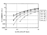
図3は、種々の材質をパラメータとした場合におけるスパッタ率の入射Snイオンエネルギー依存性を示している。イオン回収筒20に入射されるSnイオンエネルギーは、例えば0.5keV近傍である。そこで、図3を参照すると、Snイオンエネルギーが0.5keV近傍の場合、W(タングステン)、Sn(錫)、Ru(ルテニウム)、Mo(モリブデン)、Si(シリコン)、C(カーボン)の何れにおいても、スパッタ率が1未満とであることから、これらの材質でイオン回収板22の表面Saおよび内壁面Sbを形成することで、スパッタを低減できることが分かる。また、MoはSnイオンエネルギーが1keV程度以下、SiはSnイオンエネルギーが3keV程度以下、CにいたってはSnイオンエネルギーが9keV程度以下であれば、スパッタ率を1未満とすることが可能である。
FIG. 3 shows the dependence of the sputtering rate on the incident Sn ion energy when various materials are used as parameters. The Sn ion energy incident on the
さらに、図3から、Snイオンエネルギーが小さいほどスパッタ率が低減することが明らかであるため、入射されるSnイオンエネルギーを低下させること、あるいは、発生時のSnイオンエネルギー自体を小さくすることで、材料選択の幅を広げることが可能であることが分かる。特に、Snに関してもスパッタ率が1未満となるので、入射されるSnイオンエネルギーを0.5未満とすることが好ましい。これは、イオン回収筒20内部の表面に付着したSnのスパッタリングを低減できるからである。
Furthermore, since it is clear from FIG. 3 that the sputtering rate decreases as the Sn ion energy is smaller, by reducing the incident Sn ion energy, or by reducing the Sn ion energy itself at the time of generation, It can be seen that the range of material selection can be expanded. In particular, since the sputtering rate for Sn is less than 1, the incident Sn ion energy is preferably less than 0.5. This is because sputtering of Sn adhering to the surface inside the
この実施の形態1では、プリプラズマPPを生成し、このプリプラズマPPをターゲットとしてEUV光を生成している。プリプラズマPPをターゲットとして用いた場合、発生する最大Snイオンエネルギーが0.6keVであることが実験的にわかっている。したがって、表面Sa等をSiでコーティングしておくことで、このコーディング材(Si)がスパッタリングされることを低減できる。 In the first embodiment, pre-plasma PP is generated, and EUV light is generated using the pre-plasma PP as a target. It has been experimentally found that when pre-plasma PP is used as a target, the maximum Sn ion energy generated is 0.6 keV. Therefore, it is possible to reduce the sputtering of the coding material (Si) by coating the surface Sa or the like with Si.
このプリプラズマPPターゲットは、図4に示すように、ドロップレットDに強度の弱いYAGレーザ光などのプリプラズマ生成レーザ光L1を照射することで生成される。プリプラズマ生成レーザ光L1の照射により、プリプラズマPPがドロップレットDから吹き出すように生成される。EUV光の生成には、このプリプラズマPPにCO2レーザ光などのEUV光生成レーザ光L2を照射するという、2段階照射が用いられる。YAGレーザ光などのプリプラズマ生成レーザ光L1の強度は弱いため、生成されるプリプラズマPP内のSnイオンエネルギーは、CO2レーザ光などを用いた場合よりも1桁小さくなる。また、固体やドロップレットD自体をターゲットとするのではなく、プリプラズマPPをターゲットとしてEUV光を生成するため、CO2レーザ光などのEUV光生成レーザ光L2は、EUV光生成の励起エネルギー分の強度を有すればよい。これにより、EUV光生成レーザ光L2の強度を小さくすることができる。この結果、生成されるSnイオンエネルギーの初期エネルギーを小さくすることが可能となる。なお、液体SnのドロップレットDでなく、プレート、ワイヤ、リボンなどの固体ターゲットを用いた場合でも、図5に示すように、固体ターゲットDDの表面に、プリプラズマ発生レーザ光L1を照射してプリプラズマPPを吹き出すように生成し、この生成したプリプラズマPPにEUV光生成レーザ光L2を照射する2段階照射によって、生成されるSnイオンエネルギーの初期エネルギーを小さくすることができる。 As shown in FIG. 4, the pre-plasma PP target is generated by irradiating the droplet D with pre-plasma generation laser light L1 such as YAG laser light having low intensity. Pre-plasma PP is generated from the droplet D by irradiation with the pre-plasma generation laser light L1. For generation of EUV light, two-stage irradiation is used in which the pre-plasma PP is irradiated with EUV light generation laser light L2 such as CO 2 laser light. Since the intensity of the pre-plasma generation laser light L1 such as YAG laser light is weak, the Sn ion energy in the generated pre-plasma PP is one order of magnitude smaller than when CO 2 laser light or the like is used. In addition, since EUV light is generated using the pre-plasma PP as a target rather than a solid or the droplet D itself as a target, the EUV light generation laser light L2 such as CO 2 laser light is an excitation energy component of EUV light generation. It is sufficient to have the strength of Thereby, the intensity | strength of EUV light production | generation laser beam L2 can be made small. As a result, the initial energy of the generated Sn ion energy can be reduced. Even when a solid target such as a plate, a wire, or a ribbon is used instead of the liquid Sn droplet D, the surface of the solid target DD is irradiated with the pre-plasma generation laser light L1 as shown in FIG. The initial energy of the generated Sn ion energy can be reduced by two-step irradiation in which the pre-plasma PP is generated and blown out and the generated pre-plasma PP is irradiated with the EUV light generation laser light L2.
さらに、EUV光の生成に3段階以上の多段階照射を用いることで、生成されるSnイオンエネルギーの初期エネルギーをさらに小さくすることが可能である。図6は、液体SnのドロップレットDに対して3段階照射を行ってEUV光を発光する場合の状態を示す模式図である。図6に示すように、ドロップレットDに対して第1のプリプラズマ生成レーザ光LL1を照射して第1のプリプラズマPP1を生成し、さらにこの第1のプリプラズマPP1に対して第2のプリプラズマ生成レーザ光LL2を照射して第2のプリプラズマPP2を生成し、最後にこの第2のプリプラズマPP2に対してEUV光生成レーザ光LL3を照射してEUV光を生成する。この際、初期エネルギーの小さいSnイオンが生成される。このような3段階照射を用いることで、生成されるSnイオンの初期エネルギーをさらに小さくすることができるため、イオン回収板22の表面Sa等の照射面でのスパッタリングをより確実に防止することが可能となる。同様に、図7に示した固体ターゲットDDを用いた場合にも、3段階照射などの多段階照射を用いることが可能である。なお、固体ターゲットDDの場合、固体ターゲットDDの形状を、回転プレートや、移動ワイヤや、移動リボンとすることによって、プリプラズマ生成レーザ光の照射位置に常に新たなSn面を連続供給できるようにすることが好ましい。
Furthermore, the initial energy of the generated Sn ion energy can be further reduced by using three or more stages of multi-stage irradiation for EUV light generation. FIG. 6 is a schematic diagram showing a state in which EUV light is emitted by performing three-stage irradiation on the droplet D of the liquid Sn. As shown in FIG. 6, the droplet D is irradiated with the first pre-plasma generation laser beam LL1 to generate the first pre-plasma PP1, and the second pre-plasma PP1 is subjected to the second pre-plasma PP1. The pre-plasma generation laser beam LL2 is irradiated to generate the second pre-plasma PP2, and finally, the EUV light generation laser beam LL3 is irradiated to the second pre-plasma PP2 to generate EUV light. At this time, Sn ions having a small initial energy are generated. By using such three-stage irradiation, the initial energy of the generated Sn ions can be further reduced, so that sputtering on the irradiation surface such as the surface Sa of the
以上のように、この実施の形態1では、イオン回収筒20におけるSnイオンが衝突する衝突面(イオン回収板22の表面Saもしくは表面Saを覆う膜の表面)を、スパッタ率が1未満となる金属面としているので、衝突面を形成する材料のスパッタリングを防止できる。この結果、真空チャンバ10内のイオン汚染を防止することができる。また、EUV光生成過程においてプリプラズマPPを生成する多段階照射を採用することによって、Snイオンの初期エネルギーを小さくすることができるので、衝突面におけるスパッタリングをより確実に防止し、真空チャンバ10内のイオン汚染をさらに防止することができる。なお、衝突面にSnが堆積した場合であっても、Snイオンエネルギーの初期エネルギーを小さくすることによって、堆積したSnが再スパッタリングされることを低減できる。
As described above, in the first embodiment, the sputtering rate of the collision surface (the surface Sa of the
また、図8に示すように、イオンデブリによるスパッタ率は、イオン回収板22の表面Saに対するイオンデブリの入射角度に依存する。なお、図8は、Snイオンエネルギーを1keVとした場合のスパッタ率の入射角度依存性を示す図である。そこで、この実施の形態では、中心軸Cと垂直な面に対するイオン回収板22の表面Saの傾斜角度θを20°以下に抑える。これにより、スパッタ率が低減されるため、より確実にイオンデブリをイオン回収板で受け止めることが可能となる。
As shown in FIG. 8, the sputtering rate due to ion debris depends on the incident angle of ion debris with respect to the surface Sa of the
実施の形態2
上述した実施の形態1では、プリプラズマを生成する過程を含む多段階照射を採用することによって、Snイオンの初期エネルギーを小さくするようにしていた。これに対し、この実施の形態2では、ターゲットとしてマスリミテッドターゲットを用いることで、デブリとして放出されるターゲット原子の初期エネルギーを低減する。マスリミテッドターゲットとは、質量が必要なEUV光が得られる最小の質量に抑えられたターゲットである。たとえば、図9に示すマスリミテッドターゲットは、10μm径のドロップレットD1である。これにより、EUV光生成レーザ光の強度を小さくすることが可能となるため、結果的に、発生するSnイオンエネルギーの初期エネルギーを小さくすることが可能となる。具体的に、4%のEUV光変換効率を得るには、1〜5×1018cm−3程度のSn密度が必要である。これを満足するには、ノズル11aから噴出される液体SnのドロップレットD1の径が10μmであればよい。ドロップレットD1の径を10μmとした場合にEUV光生成レーザ光L2に要求されるパワーは、1010W/cm2程度である。なお、マスリミテッドターゲットに上述した多段階照射を組み合わせることで、Snイオンエネルギーをさらに低減させることも可能である。
Embodiment 2
In the first embodiment described above, the initial energy of Sn ions is reduced by employing multi-step irradiation including a process of generating pre-plasma. On the other hand, in this Embodiment 2, the initial energy of the target atom discharge | released as a debris is reduced by using a mass limited target as a target. The mass limited target is a target that is suppressed to a minimum mass that can obtain EUV light requiring a mass. For example, the mass limited target shown in FIG. 9 is a droplet D1 having a diameter of 10 μm. As a result, the intensity of the EUV light generation laser light can be reduced, and as a result, the initial energy of the generated Sn ion energy can be reduced. Specifically, to obtain EUV light conversion efficiency of 4%, an Sn density of about 1 to 5 × 10 18 cm −3 is necessary. In order to satisfy this, the diameter of the droplet Sn of the liquid Sn ejected from the nozzle 11a may be 10 μm. When the diameter of the droplet D1 is 10 μm, the power required for the EUV light generation laser light L2 is about 10 10 W / cm 2 . In addition, it is also possible to further reduce Sn ion energy by combining the multi-stage irradiation described above with a mass limited target.
また、図10に示すように、マスリミテッドターゲットとしてナノ粒子含有ターゲットD2を用いても良い。このナノ粒子含有ターゲットD2は、ナノサイズのSn微粒子を水やアルコールに含有させてノズル11bから射出したものであり、ターゲットの質量をより小さくすることができる。この場合も、ターゲットの質量が必要なEUV光を得る最小の質量となるため、必要なEUV光生成レーザ光の強度を小さくすることができ、結果的に、生成されるSnイオンエネルギーをさらに低減させることができる。 Moreover, as shown in FIG. 10, you may use the nanoparticle containing target D2 as a mass limited target. The nanoparticle-containing target D2 is obtained by injecting nano-sized Sn fine particles into water or alcohol and ejecting from the nozzle 11b, so that the mass of the target can be further reduced. Also in this case, since the target mass becomes the minimum mass for obtaining the required EUV light, the intensity of the required EUV light generation laser light can be reduced, and as a result, the generated Sn ion energy is further reduced. Can be made.
さらに、図11に示すようなマスリミテッドターゲットD3を用いても良い。このマスリミテッドターゲットD3は、透明基板29表面上にSn膜であるターゲット膜DD3を形成しておき、透明基板29の裏面からマスリミテッドターゲット生成レーザ光L4を照射してターゲット膜DD3のSnを剥離させることで生成することができる。剥離したSnは、必要なEUV光生成のための最小質量をもつSn微粒子の状態で、透明基板29表面上方に飛び出す。これにより、必要なEUV光生成のための最小質量をもつSn微粒子であるマスリミテッドターゲットD3が分散生成される。その後、この分散生成されたマスリミテッドターゲットD3群に対してEUV光生成レーザ光L2を照射することによって、EUV光が生成される。この場合も、ターゲットの質量を必要なEUV光を得る最小の質量とすることが可能となるため、必要なEUV光生成レーザ光L2の強度を小さくすることができ、結果的に、生成されるSnイオンエネルギーをさらに低減させることができる。
Further, a mass limited target D3 as shown in FIG. 11 may be used. In this mass limited target D3, a target film DD3 that is a Sn film is formed on the surface of the
実施の形態3
つぎに、この発明の実施の形態3について説明する。図12は、この発明の実施の形態3による極端紫外光光源装置の構成を示す断面図である。この実施の形態3では、磁場の中心軸C上に配置された、対向する一対のイオン回収筒30aおよび30bが設けられる。この一対のイオン回収筒30aおよび30bによって、磁場の中心軸Cに沿って収束しつつイオン流FL1およびFL2となって移動するSnイオンが回収される。このイオン回収筒30aおよび30bは、Snイオンの入射側に接地されたグリッド電極33aおよび33bを備えるとともに、底部側に高い正電位が印加されたイオン回収板32aおよび32bを備える。この構成により、グリッド電極33aおよび33bとイオン回収板32aおよび32bとの間にそれぞれかかる電界によって入射するSnイオンの速度が低下するため、イオン回収板32a,32bに衝突する際のSnイオンエネルギーを小さくすることが可能となる。すなわち、入射する正イオンであるSnイオンは、クーロン力Fを受けて速度が減少されて、Snイオンエネルギーが小さくなる。これによって、イオン回収板32aおよび32bの衝突面でのスパッタ率を低減することができる。なお、ドロップレットDに対して直接、EUV光生成レーザ光L2を照射してプラズマを生成することでEUV光を生成する場合、発生したSnイオンは、磁場の中心軸Cの両側に移動していく。そこで、本実施の形態3では、2つのイオン回収筒30aおよび30bを設けている。
Embodiment 3
Next, a third embodiment of the present invention will be described. FIG. 12 is a sectional view showing a configuration of an extreme ultraviolet light source apparatus according to Embodiment 3 of the present invention. In the third embodiment, a pair of opposing ion recovery cylinders 30a and 30b disposed on the central axis C of the magnetic field are provided. By this pair of ion recovery cylinders 30a and 30b, Sn ions moving as ion flows FL1 and FL2 while being converged along the central axis C of the magnetic field are recovered. The ion recovery cylinders 30a and 30b include grid electrodes 33a and 33b grounded on the Sn ion incident side and ion recovery plates 32a and 32b to which a high positive potential is applied on the bottom side. With this configuration, the speed of Sn ions incident by the electric field between the grid electrodes 33a and 33b and the ion recovery plates 32a and 32b is reduced, so that the Sn ion energy when colliding with the ion recovery plates 32a and 32b is reduced. It can be made smaller. That is, incident Sn ions, which are positive ions, receive the Coulomb force F, the velocity is reduced, and the Sn ion energy is reduced. Thereby, the sputtering rate at the collision surface of the ion recovery plates 32a and 32b can be reduced. When EUV light is generated by directly irradiating the droplet D with the EUV light generation laser light L2 to generate plasma, the generated Sn ions move to both sides of the central axis C of the magnetic field. Go. Therefore, in the third embodiment, two ion collection cylinders 30a and 30b are provided.
また、この実施の形態3では、イオン回収板32aおよび32bの衝突面にスパッタ率が小さいMoを配置している。このように衝突面にMoを用いた場合や上述の実施の形態1のようにSiを用いた場合、MoやSiはEUV光集光ミラー14のEUV光反射多層膜を形成する物質でもあるので、たとえSnイオンによってスパッタリングされて真空チャンバ10内に飛び出したとしても、その影響を小さくすることができる。
In the third embodiment, Mo having a low sputtering rate is disposed on the collision surface of the ion recovery plates 32a and 32b. Thus, when Mo is used for the collision surface or when Si is used as in the first embodiment, Mo or Si is also a substance that forms the EUV light reflecting multilayer film of the EUV
以上のように、この実施の形態3では、イオン回収筒30a,30bに入射するSnイオンの速度を電界によって低減するため、イオン回収板32a,32bの衝突面に衝突するSnイオンエネルギーを小さくすることが可能となる。この結果、Snイオンによって衝突面がスパッタリングされることを防止することができる。 As described above, in the third embodiment, the Sn ion energy that collides with the collision surfaces of the ion recovery plates 32a and 32b is reduced in order to reduce the speed of Sn ions incident on the ion recovery tubes 30a and 30b by the electric field. It becomes possible. As a result, it is possible to prevent the collision surface from being sputtered by Sn ions.
実施の形態4
つぎに、この発明の実施の形態4について説明する。この実施の形態4では、低速イオン流ターゲットを生成し、この低速イオン流ターゲットにEUV光生成レーザ光を照射することによってEUV光を生成する。低速イオン流ターゲットを用いることで、発生するSnイオンエネルギーを小さくすることが可能である。
Embodiment 4
Next, a fourth embodiment of the present invention will be described. In the fourth embodiment, EUV light is generated by generating a low-speed ion flow target and irradiating this low-speed ion flow target with EUV light generation laser light. By using a low-speed ion flow target, it is possible to reduce the generated Sn ion energy.
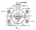
図13に示すように、この実施の形態4による極端紫外光光源装置は、真空チャンバとしてイオン生成真空チャンバ10bとEUV光生成真空チャンバ10aとを有する。イオン生成真空チャンバ10bとEUV光生成真空チャンバ10aとは、隣接配置され、磁場の中心軸Cを通る開口部30によって連通している。
As shown in FIG. 13, the extreme ultraviolet light source device according to the fourth embodiment includes an ion
イオン生成真空チャンバ10b内には、ドロップレットノズル31が配置される。このドロップレットノズル31からは、イオン生成真空チャンバ10b内へ向けて、溶融SnのドロップレットDが噴出される。また、イオン生成真空チャンバ10bには、イオン流生成レーザ32から出射されるイオン流生成レーザ光L11を通すウィンドウW11が設けられる。イオン流生成レーザ光L11は、このウィンドウW11を介してドロップレットDに照射される。このドロップレットDに対するイオン流生成レーザ光L11の照射によって、プリプラズマPPが生成される。ここで、プリプラズマPPが発生する位置は、磁場の中心軸C近傍である。イオン流生成レーザ光L11は、イオン回収筒20側から照射されるため、プリプラズマPPは、ドロップレットDに対してイオン回収筒20側に生成される。その後、プリプラズマPPは、磁場の中心軸C近傍に収束しつつ中心軸Cに沿ってイオン回収筒20側に移動する。
A droplet nozzle 31 is disposed in the ion
このプリプラズマPPには、Snイオン以外に、微粒子や中性粒子などの耐電していないデブリも含まれる。これらのデブリは、磁場の影響を受けないので、イオン生成真空チャンバ10b内に拡散していく。なお、ドロップレットノズル31の対向する位置には、残存ドロップレットを回収するドロップレット回収部34が設けられる。
In addition to Sn ions, the pre-plasma PP includes non-electrically resistant debris such as fine particles and neutral particles. Since these debris is not affected by the magnetic field, it diffuses into the ion
中心軸Cに沿ってイオン回収筒20側に移動するSnイオンは、開口部30を通ってEUV光生成真空チャンバ10a内に移動する。この開口部30は、移動するSnイオン束の径とほぼ同じ径であり、十分に小さい。したがって、上述した拡散するデブリである微粒子や中性粒子は、ほとんどEUV光生成真空チャンバ10a内に入ることができない。また、たとえデブリが開口部30を通過しても、このデブリの移動は指向性があるので、そのほとんどをイオン回収筒20によって回収することが可能である。この結果、EUV光集光ミラー14などデブリが付着することを防止できる。
Sn ions that move toward the
EUV光生成真空チャンバ10aは、ウィンドウW12を有する。EUV光生成レーザ13から出射されたEUV光生成レーザ光L2は、このウィンドウW12を介してEUV光生成真空チャンバ10a内に入射する。EUV光集光ミラー14の集光位置は、中心軸C上に配置される。EUV光生成レーザ光L2は、この中心軸Cに沿って移動する低速Snイオン流FL3が集光位置P3に到達したタイミングで照射される。これにより、EUV光が生成されるとともに、Snイオンが生成される。
The EUV light
図14は、Snイオンが上述した磁場によってイオン生成真空チャンバ10bからEUV光生成真空チャンバ10aに移動する状態を模式的に示している。この低速Snイオン流FL3は、そのほとんどがSnイオンである。したがって、EUV光の発光のみに必要な強度をもった小さいパワーのEUV光生成レーザ光L2をターゲットである低速Snイオンに照射すればよいため、結果的に、発生するSnイオンのエネルギーを小さくすることができる。これにより、イオン回収筒20のイオン回収板22に到達するSnイオンエネルギーがたとえば0.5keV未満となり、この結果、衝突面のスパッタ率を1未満とすることができる。
FIG. 14 schematically shows a state in which Sn ions move from the ion
なお、低速イオンのみをEUV光生成真空チャンバ10aに導入する手法としては、マグネット15aおよび15bによる磁場を用いて低速Snイオンを収束させつつ移動させる手法のみならず、たとえば、図15に示すように、イオン生成真空チャンバ10b内で低速イオン流FL3の流れ方向に対して垂直に磁場または電場を発生させることで、イオン化されていない重い非イオン化デブリと低速のSnイオンとを分離すると共に、低速のSnイオンが分離される位置に開口部30を設ける手法を用いることもできる。このような手法によれば、分離されたSnイオンが開口部30を介してそのまま直線的にEUV光生成真空チャンバ10a内に移動することで、低速イオン流FL3が形成される。この場合、非イオン化デブリを捕捉するスパッタ防止膜35を、非イオン化デブリが分離されて拡散する位置に設けることが好ましい。なお、図15では、ターゲットにドロップレットを用いた場合を例示した。ただし、これに限るものではない。たとえば図16に示すように、固体のターゲットであるプレートDDを用いた場合も同様である。固体ターゲットとしては、上述したように、プレートの他に、ワイヤやリボンがある。
As a method of introducing only low-speed ions into the EUV light
以上のように、この実施の形態4では、Snイオンのみを取り出すイオン生成真空チャンバ10bを備えると共に、イオン生成真空チャンバ10bから導入されたSnイオンのみに対してEUV光生成レーザ光L2を照射してEUV光を発光出力する構成を備えているため、発生するSnイオンのエネルギーを低減することができ、結果的に、衝突面のスパッタ率を1未満とすることができる。
As described above, the fourth embodiment includes the ion
実施の形態5
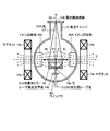
上述した実施の形態4では、イオン生成真空チャンバ10b内でプラズマを生成させ、このプラズマからSnイオンのみを取り出してEUV光生成真空チャンバ10a内に流入させてEUV光を発光出力させた。これに対し、この実施の形態5では、図17に示すように、金属蒸気生成チャンバ10c内で、蒸気生成用レーザ光L21をドロップレットDに照射してターゲット材であるSnを蒸発させる。この蒸発したSn蒸気を、Sn蒸気流FL4として開口部30を介してEUV光生成真空チャンバ10a内に蒸気の拡散によって流入させる。
In Embodiment 4 described above, plasma is generated in the ion
EUV光生成真空チャンバ10a内に流入したSn蒸気流FL4には、EUV光生成レーザ光L2が照射される。これにより、EUV光が生成されるとともに、Snイオンが生成される。この場合、EUV光生成レーザ光L2が照射されるSnは、ガス状であるため、EUV光を生成するのに必要なレーザ光量は小さくてよい。この結果、発生するSnイオンのエネルギーを小さくすることができる。これにより、イオン回収筒20の衝突面がスパッタリングされることを防止できる。なお、開口部30は、径が小さいため発生したSn蒸気から、ある指向性をもった蒸気のみをEUV光生成真空チャンバに導くことができる。つまり、Sn蒸気流FL4は、EUV光生成真空チャンバ10a内において指向性をもって移動する。
The Sn vapor flow FL4 that has flowed into the EUV light
また、図17では、ターゲットに溶融SnのドロップレットDを使用した場合を例示した。ただし、これに限るものではない。たとえば、図18に示すように、固体のターゲットであるプレートDDを用いた場合も同様に、Sn蒸気流FL4を生成することができる。なお、本実施の形態5では、ターゲット材に蒸気生成用レーザ光L21を照射してSn蒸気を発生した。ただし、これに限らず、たとえばレーザ光以外に熱源から供給される熱を用いてターゲット材を蒸発させることでSn蒸気を発生させるなど、Sn蒸気を発生させることが可能な種々の方法を用いることが可能である。 Moreover, in FIG. 17, the case where the droplet D of molten Sn was used for the target was illustrated. However, the present invention is not limited to this. For example, as shown in FIG. 18, the Sn vapor flow FL4 can be generated in the same manner when a plate DD that is a solid target is used. In the fifth embodiment, Sn vapor is generated by irradiating the target material with the laser beam L21 for vapor generation. However, the present invention is not limited to this, and various methods capable of generating Sn vapor are used, for example, Sn vapor is generated by evaporating a target material using heat supplied from a heat source other than laser light. Is possible.
実施の形態6
つぎに、この発明の実施の形態6について説明する。この実施の形態6では、イオン回収筒の前段あるいはイオン回収筒内であってイオン回収板の前段に、Snイオンと衝突するガス領域が設けられる。このガス領域によってSnイオンを減速することが可能となるため、衝突時のSnイオンエネルギーを小さくして衝突面におけるスパッタリングを防止することが可能となる。
Embodiment 6
Next, a sixth embodiment of the present invention will be described. In the sixth embodiment, a gas region that collides with Sn ions is provided in the front stage of the ion recovery cylinder or in the ion recovery cylinder and in front of the ion recovery plate. Since Sn gas can be decelerated by this gas region, it is possible to reduce the Sn ion energy at the time of collision and prevent sputtering at the collision surface.
図19は、この発明の実施の形態6による極端紫外光光源装置の構成を示す断面図である。この実施の形態6では、図13に示したイオン回収筒20に替えて、ガス領域を有するイオン回収筒40が設けられるとともに、EUV光生成真空チャンバ10aとイオン回収筒40との間にバッファ筒50が設けられる。
FIG. 19 is a cross-sectional view showing the configuration of an extreme ultraviolet light source apparatus according to Embodiment 6 of the present invention. In the sixth embodiment, an
イオン回収筒40の形状は、イオン回収筒20と同様に、円筒形である。また、イオン回収筒40は、EUV光生成真空チャンバ10a側に開口部45が形成されている。さらに、イオン回収筒40は、イオン回収板22に対応する円錐状のイオン回収板42を有する。このイオン回収板42の表面およびイオン回収筒40の内壁面には、低スパッタ材としてのSi膜が形成されている。イオン回収板42の表面とイオン回収筒40の内壁面とで区画される空間には、希ガスなどのガスで充填されたガス領域が形成される。開口部45から入射したSnイオンは、希ガスと衝突することによって、Snイオンエネルギーが奪われるため、Snイオンの速度が低減する。この結果、イオン回収板42の表面などが、Snイオンによってスパッタリングされにくくなる。
The shape of the
イオン回収筒40内への希ガスの充填は、ガス供給部41によって行われる。ガス領域のガスは、希ガスに限らず、水素やハロゲンの原子または分子でもよく、もしくはこれらの混合ガスであってもよい。
The
なお、上述したように、EUV光生成真空チャンバ10aとイオン回収筒40との間には、バッファ筒50が設けられる。Snイオンは、このバッファ筒50を介してイオン回収筒40に移動する。バッファ筒50において、ガス供給部41から供給されたガスは、ポンプ51によって差動排気される。これにより、EUV光生成真空チャンバ10a内へのガスが混入することが防止される。
As described above, the
また、ガス領域の中心軸C方向の長さは、長い方が好ましい。これは、ガス領域を長くすることで、Snイオンとガスとの衝突回数を増加させることが可能となるため、結果的に、Snイオンを大きく減速することが可能となるためである。ただし、ガス領域を長くするとイオン回収筒40の長さも大きくなる。そこで、たとえば図20に示すように、Snイオン流に垂直な方向に一対の磁石64aおよび64bを設け、この一対の磁石64aおよび64bを用いてガス領域に磁場Bをかけることが好ましい。これにより、Snイオンをローレンツ力によって回転運動させつつ移動させることが可能となる。この場合、Snイオンが移動する軌跡が螺旋状となるため、ガス領域の長さが短い場合でも、移動距離を長くすることが可能となる。この結果、ガスとSnイオンとの衝突回数を増加させることが可能となる。
The length of the gas region in the direction of the central axis C is preferably long. This is because by increasing the gas region, the number of collisions between Sn ions and gas can be increased, and as a result, Sn ions can be greatly decelerated. However, when the gas region is lengthened, the length of the
以上のように、この実施の形態6では、イオン回収筒の前段あるいはイオン回収筒内であってイオン回収板の前段にSnイオンと衝突するガス領域が設けられているため、イオン回収筒に入射したSnイオンを減速させることが可能となる。これにより、イオン回収板に入射するSnイオンのエネルギーを小さくすることが可能となるため、衝突面におけるスパッタリングを防止することができる。 As described above, in the sixth embodiment, the gas region that collides with the Sn ions is provided in the front stage of the ion recovery cylinder or in the ion recovery cylinder and in front of the ion recovery plate. It is possible to decelerate the Sn ions. As a result, the energy of Sn ions incident on the ion recovery plate can be reduced, so that sputtering on the collision surface can be prevented.
実施の形態7
つぎに、この発明の実施の形態7を、図面を用いて詳細に説明する。図21は、この発明の実施の形態7による極端紫外光光源装置の構成を示す断面図である。ただし、図21には、EUV光L3の出力方向DEとマグネット15aおよび15bが形成する磁場の中心軸Cとの双方を含む面で極端紫外光光源装置を切断した際の断面図を示す。
Embodiment 7
Next, a seventh embodiment of the present invention will be described in detail with reference to the drawings. FIG. 21 is a cross-sectional view showing a configuration of an extreme ultraviolet light source apparatus according to Embodiment 7 of the present invention. However, FIG. 21 shows a cross-sectional view of the extreme ultraviolet light source device cut along a plane including both the output direction DE of the EUV light L3 and the central axis C of the magnetic field formed by the
上述した各実施の形態では、真空チャンバ10の外側にイオン回収筒20、30aおよび30b、または、40が配置された場合を例に挙げた。これに対し、本実施の形態7では、イオン回収筒20Aを真空チャンバ10の中に配置する。そこで本実施の形態7では、図21に示すように、マグネット15aおよび15bは、EUV光L3の出力方向DEと垂直な軸であってプラズマ発光点P1を通る中心軸Cを含む磁場が形成されるように、真空チャンバ10の外に配置される。一対のイオン回収筒20Aは、イオンデブリの入射方向が中心軸Cと一致し且つプラズマ発光点P1を挟むように配置される。なお、図21では、一対のイオン回収筒20Aを用いる場合を例に挙げる。ただし、これに限定されず、1つのイオン回収筒20Aを備えた構成であってもよい。
In each of the above-described embodiments, the case where the
真空チャンバ10のウィンドウW2、レーザ集光光学系14bおよびEUV光集光ミラー14の孔14aを介してEUV光集光ミラー14の背面からプラズマ発光点P1のドロップレットDにEUV光生成レーザ光13が照射されると、プラズマ化したドロップレットDからEUV光L3が放射されると共に、プラズマ発光点P1の周囲にイオンデブリが発生する。プラスに帯電したイオンデブリは、マグネット15aおよび15bが形成する磁場によって収束しつつイオン流FLとなって中心軸Cに沿って移動する。その結果、中心軸C上に配置されたイオン回収筒20Aによって回収される。なお、イオン回収筒20Aは、上述した実施の形態1〜6のいずれかによるイオン回収筒20、30aおよび30b、または、40であってよい。また、プラズマ発光点P1においてプラズマ化したドロップレットDから放射されたEUV光L3は、EUV光集光ミラー14によって出力方向DEへ向けて集光するように反射されることで、露光機接続部10Aから出力される。
EUV light generation laser light 13 from the back surface of the EUV
このように、イオン回収筒20Aを真空チャンバ10内部に設けることで、極端紫外光光源装置のコンパクト化が可能になると共に、マグネット15aおよび15bを固定したままで真空チャンバ10を引き出すことが可能になる。この結果、真空チャンバ10に対するメンテナンス作業などを容易化することが可能となる。なお、その他の構成、動作および効果は、上述した実施の形態およびその変形例と同様であるため、ここでは詳細な説明を省略する。
Thus, by providing the ion collection cylinder 20A inside the
実施の形態8
つぎに、この発明の実施の形態8を、図面を用いて詳細に説明する。図22は、この実施の形態8による極端紫外光光源装置の構成を示す断面図である。また、図23は、この実施の形態8におけるオブスキュレーション領域とイオン回収筒との位置関係を示す模式図である。
Embodiment 8
Next, an eighth embodiment of the present invention will be described in detail with reference to the drawings. FIG. 22 is a cross-sectional view showing the configuration of the extreme ultraviolet light source device according to the eighth embodiment. FIG. 23 is a schematic diagram showing the positional relationship between the obscuration region and the ion collection cylinder in the eighth embodiment.
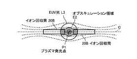
図22に示すように、この実施の形態8による極端紫外光光源装置は、図22に示す極端紫外光光源装置と同様の構成において、一対のイオン回収筒20Aが一対のイオン回収筒20Bに置き換えられている。イオン回収筒20Bは、イオン回収筒20Aと同様に、イオンデブリの入射方向が中心軸Cと一致し且つプラズマ発光点P1を挟むように配置される。ただし、この実施の形態8では、図23に示すように、イオン回収筒20Bは、その少なくとも一部(先端部分)が、EUV光L3の影となる領域であるオブスキュレーション領域E2内に位置するように、真空チャンバ10内に配置される。なお、オブスキュレーション領域とは、EUV光集光ミラー14によって集光されるEUV光L3が露光機において利用されない角度範囲に対応する領域のことをいう。すなわち、この説明では、露光機11における露光に利用されない角度範囲に対応する3次元的な体積領域をオブスキレーション領域E2という。EUV露光機11における露光に寄与しないオブスキュレーション領域E2内にイオン回収筒20Bを配置することで、露光機の露光性能やスループットに影響が生じることを回避できる。
As shown in FIG. 22, the extreme ultraviolet light source device according to the eighth embodiment has the same configuration as that of the extreme ultraviolet light source device shown in FIG. 22, and the pair of ion recovery cylinders 20A is replaced with a pair of ion recovery cylinders 20B. It has been. Similar to the ion collection cylinder 20A, the ion collection cylinder 20B is arranged such that the incident direction of ion debris coincides with the central axis C and sandwiches the plasma emission point P1. However, in the eighth embodiment, as shown in FIG. 23, the ion collection cylinder 20B has at least a portion (tip portion) positioned in the obscuration region E2 which is a region that is a shadow of the EUV light L3. As shown in FIG. Note that the obscuration region refers to a region corresponding to an angular range in which the EUV light L3 collected by the EUV
このように、少なくとも一部(先端部分)がオブスキュレーション領域E2内に位置するようにイオン回収筒20Bを配置することで、イオンデブリの発生箇所(プラズマ発光点P1近傍)とイオン回収筒20Bの開口部分とを近接させることが可能となるため、より効率的かつ確実にイオンデブリを回収することが可能となる。なお、その他の構成、動作および効果は、上述した実施の形態7と同様であるため、ここでは詳細な説明を省略する。また、図22および図23では、イオン回収筒20Bを用いる場合を例に挙げた。ただし、これに限定されず、1つのイオン回収筒20Bを備えた構成であってもよい。また、各イオン回収筒20Bは、上述した実施の形態1〜6のいずれかによるイオン回収筒20、30aおよび30b、または、40であってよい。
In this way, by arranging the ion collection cylinder 20B so that at least a part (tip part) is located in the obscuration region E2, the ion debris generation site (the vicinity of the plasma emission point P1) and the ion collection cylinder 20B are arranged. Therefore, it is possible to collect ion debris more efficiently and reliably. Since other configurations, operations, and effects are the same as those of the above-described seventh embodiment, detailed description thereof is omitted here. 22 and 23 exemplify the case where the ion collection cylinder 20B is used. However, it is not limited to this, The structure provided with one ion collection cylinder 20B may be sufficient. Further, each ion recovery cylinder 20B may be the
実施の形態9
つぎに、この発明の実施の形態9を、図面を用いて詳細に説明する。この実施の形態9では、上述した各実施の形態におけるイオン回収筒の他の形態を例示する。図24は、この実施の形態9によるイオン回収筒80の構成を示す断面図である。上述した実施の形態では、円錐形のイオン回収板22または42もしくは平板状のイオン回収板32aまたは32bが底に配置されたイオン回収筒20,30a、30bまたは40を用いていた。これに対し、この実施の形態9では、図24に示すようなイオン回収筒80を用いる。
Embodiment 9
Next, a ninth embodiment of the present invention will be described in detail with reference to the drawings. In the ninth embodiment, another form of the ion recovery cylinder in each of the above-described embodiments is illustrated. FIG. 24 is a cross-sectional view showing the configuration of the
図24に示すように、この実施の形態9によるイオン回収筒80は、イオン衝突面が磁場の中心軸Cと垂直な面に対して傾いた平板状のイオン回収板82を用いる。これにより、イオン回収板82に対するイオンデブリFIの入射角度を、例えば20°以下に抑えてスパッタ率を低く維持しながら、重力を利用して回収を容易にすることが可能となる。本形態におけるイオン回収板82は平板状であり、円錐形のイオン回収板22を用いる実施の形態1に比べて加工が容易であるため低コストで構成できる。なお、その他の構成、動作および効果は、上述した実施の形態と同様であるため、ここでは詳細な説明を省略する。
As shown in FIG. 24, the
実施の形態10
つぎに、この発明の実施の形態10を、図面を用いて詳細に説明する。この実施の形態10では、上述した各実施の形態におけるイオン回収板の他の形態を例示する。図25は、この実施の形態10によるイオン回収板92の構成を示す模式図である。上述した実施の形態では、円錐形のイオン回収板22または42、もしくは、平板状のイオン回収板32a,32bまたは82を用いていた。これに対し、この実施の形態10では、図25に示すようなイオン回収板92を用いる。
Next, a tenth embodiment of the present invention will be described in detail with reference to the drawings. In the tenth embodiment, another form of the ion recovery plate in each of the above embodiments is illustrated. FIG. 25 is a schematic diagram showing the configuration of the
図25に示すように、この実施の形態10によるイオン回収板92は、イオン衝突面が磁場の中心軸Cと垂直な面に対してねじれるように傾いた複数のフィン92aよりなるスクリュー状のイオン回収板92を用いる。これにより、イオン回収板92のイオン衝突面(フィン92aの表面)に対するイオンデブリFIの入射角度をある程度(例えば20°以下)に抑えることが可能となるため、イオンデブリFIをより確実にイオン回収板92で受け止めることが可能となる。なお、その他の構成、動作および効果は、上述した実施の形態と同様であるため、ここでは詳細な説明を省略する。
As shown in FIG. 25, the
また、上記実施の形態およびその変形例は本発明を実施するための例にすぎず、本発明はこれらに限定されるものではなく、仕様等に応じて種々変形することは本発明の範囲内であり、更に本発明の範囲内において、他の様々な実施の形態が可能であることは上記記載から自明である。さらに、上述の各実施の形態およびその変形例は、相互に適宜組み合わせることが可能である。 In addition, the above-described embodiment and its modifications are merely examples for carrying out the present invention, and the present invention is not limited to these, and various modifications according to specifications and the like are within the scope of the present invention. Furthermore, it is obvious from the above description that various other embodiments are possible within the scope of the present invention. Furthermore, the above-described embodiments and modifications thereof can be appropriately combined with each other.
さらに、上記実施の形態およびその変形例では、ターゲット物質のプリプラズマ生成用レーザによって、発生したプリプラズマにレーザ光を照射して前記極端紫外光を発生させる例を示した。しかし、これらの例に限定されることなく、たとえば、ターゲット物質に少なくとも1以上レーザ光を照射することによって、ターゲットを膨張させる。そして、極端紫外光が発生するのに最適な大きさに膨張したターゲットに対して、さらに、レーザ光を照射して極端紫外光を効率よく発生させてもよい。ここで、膨張したターゲットとは、ターゲットのクラスター、蒸気、微粒子、プラズマの内のいずれか1を含む状態である。 Furthermore, in the said embodiment and its modification, the laser beam was irradiated to the generated pre-plasma with the laser for pre-plasma generation of a target material, and the example which generates the said extreme ultraviolet light was shown. However, the present invention is not limited to these examples. For example, the target is expanded by irradiating the target material with at least one laser beam. The target that has expanded to an optimum size for generating extreme ultraviolet light may be further irradiated with laser light to efficiently generate extreme ultraviolet light. Here, the expanded target is a state including any one of target clusters, vapor, fine particles, and plasma.
1 極端紫外光光源装置
10 真空チャンバ
10A 露光機接続部
10a EUV光生成真空チャンバ
10b イオン生成真空チャンバ
11,31 ドロップレットノズル
11a,11b ノズル
12 プリプラズマ生成レーザ
13 EUV光生成レーザ
14 EUV光集光ミラー
14a 孔
14b レーザ集光光学系
15a,15b マグネット
20,20A,20B,20a,30a,30b,40,60 イオン回収筒
21,25a 開口
22,32a,32b,42,62 イオン回収板
23 冷却ノズル
24,27a,28a 温度センサ
24b,27b,28b 温調器
25 排出筒
26 回収部
27,28 ヒータ
29 透明基板
30,45,55 開口部
32 イオン流生成レーザ
33a,33b グリッド電極
34 ドロップレット回収部
41,61 ガス供給部
50 バッファ筒
51 ポンプ
64a,64b 磁石
W1,W2,W11,W12 ウィンドウ
C 中心軸
DE 出力方向
PP プリプラズマ
L1 プリプラズマ生成レーザ光
L2 EUV光生成レーザ光
L3 EUV光
L11 イオン流生成レーザ光
FL3 低速Snイオン流
FL4 Sn蒸気流
E2 オブスキュレーション領域
DESCRIPTION OF
Claims (13)
重力方向に対して傾き且つ前記磁場または前記電場によって制御された前記イオンの流れ方向に対して傾いて配置されたイオン衝突面を備え、前記イオン衝突面に入射したイオンを回収するイオン回収部と、
前記イオン衝突面の温度を前記ターゲットが過熱せず且つ溶融する温度以上に調節する温度調節部と、
を備え、
前記イオン衝突面は、前記イオンによるスパッタ率が1原子/イオン未満となる材質で構成されていることを特徴とする極端紫外光光源装置。 In an extreme ultraviolet light source device that generates plasma by irradiating a target with laser light, generates extreme ultraviolet light from the plasma, and controls the flow direction of ions generated along with the generation of this extreme ultraviolet light by a magnetic field or an electric field.
An ion recovery unit that includes an ion collision surface that is inclined with respect to the direction of gravity and is inclined with respect to the flow direction of the ions controlled by the magnetic field or the electric field, and that collects ions incident on the ion collision surface; ,
A temperature adjusting unit that adjusts the temperature of the ion collision surface to a temperature at which the target does not overheat and melts; and
With
The ion collision surface is an extreme ultraviolet light source device characterized by sputter rate by the ion is made of a material which is less than 1 atom / ion.
前記イオン衝突面の材料は、W、Sn、Ru、Mo、SiまたはCであることを特徴とする請求項1に記載の極端紫外光光源装置。 The target material is Sn,
2. The extreme ultraviolet light source device according to claim 1, wherein a material of the ion collision surface is W, Sn, Ru, Mo, Si, or C. 3.
前記ターゲット物質のプラズマおよび/または蒸気をプリプラズマとして生成する1以上のプリプラズマ生成レーザと、
前記生成されたプリプラズマにレーザ光を照射して前記極端紫外光を発生させる極端紫外光生成レーザと、
を備えたことを特徴とする請求項3に記載の極端紫外光光源装置。 The reduction mechanism is
One or more pre-plasma generating lasers that generate plasma and / or vapor of the target material as pre-plasma;
An extreme ultraviolet light generating laser for generating the extreme ultraviolet light by irradiating the generated pre-plasma with laser light;
The extreme ultraviolet light source device according to claim 3, comprising:
前記生成された膨張したターゲットにレーザ光を照射して前記極端紫外光を発生させる極端紫外光生成レーザと、
を備えたことを特徴とする請求項3に記載の極端紫外光光源装置。 One or more lasers producing an expanded target of the target material;
An extreme ultraviolet light generating laser for generating the extreme ultraviolet light by irradiating the generated expanded target with laser light;
The extreme ultraviolet light source device according to claim 3, comprising:
前記ターゲットからプラズマを生成するとともに該プラズマからイオンを分離出力するプラズマ生成チャンバと、
前記分離出力されたイオンにレーザ光を照射して極端紫外光を発生して外部出力する極端紫外光生成チャンバと、
を備えたことを特徴とする請求項3〜7のいずれか一つに記載の極端紫外光光源装置。 The reduction mechanism is
A plasma generation chamber for generating plasma from the target and separating and outputting ions from the plasma;
An extreme ultraviolet light generation chamber that emits extreme ultraviolet light by irradiating the separated and output ions with laser light, and outputs the ultraviolet light externally;
The extreme ultraviolet light source device according to any one of claims 3 to 7, further comprising:
前記ターゲットからターゲット蒸気を生成する蒸気生成チャンバと、
前記ターゲット蒸気にレーザ光を照射して極端紫外光を発生して外部出力する極端紫外光生成チャンバと、
を備えたことを特徴とする請求項3〜8のいずれか一つに記載の極端紫外光光源装置。 The reduction mechanism is
A steam generation chamber for generating target steam from the target;
An extreme ultraviolet light generation chamber that emits extreme ultraviolet light by irradiating the target vapor with laser light and outputs it externally;
The extreme ultraviolet light source device according to any one of claims 3 to 8, further comprising:
イオン衝突面に前記イオンによるスパッタ率が1原子/イオン未満となる材質が配置またはコートされた、前記イオンを回収するイオン回収装置と、
前記プラズマ発生点からイオン衝突面までの間に設けられ、前記イオンを前記ターゲットの材料のスパッタ率が1未満となるイオンエネルギーに低減する低減機構と、
を備え、
前記低減機構は、
前記ターゲットからプラズマを生成するとともに該プラズマからイオンを分離出力するプラズマ生成チャンバと、
前記分離出力されたイオンにレーザ光を照射して極端紫外光を発生して外部出力する極端紫外光生成チャンバと、
を備えたことを特徴とする極端紫外光光源装置。 In an extreme ultraviolet light source device that generates plasma by irradiating a target with laser light, generates extreme ultraviolet light from the plasma, and controls the flow direction of ions generated along with the generation of this extreme ultraviolet light by a magnetic field or an electric field.
An ion recovery device for recovering the ions, wherein a material whose sputtering rate by the ions is less than 1 atom / ion is disposed or coated on an ion collision surface;
A reduction mechanism which is provided between the plasma generation point and the ion collision surface and reduces the ions to ion energy at which the sputtering rate of the target material is less than 1.
With
The reduction mechanism is
A plasma generation chamber for generating plasma from the target and separating and outputting ions from the plasma;
An extreme ultraviolet light generation chamber that emits extreme ultraviolet light by irradiating the separated and output ions with laser light, and outputs the ultraviolet light externally;
An extreme ultraviolet light source device characterized by comprising:
イオン衝突面に前記イオンによるスパッタ率が1原子/イオン未満となる材質が配置またはコートされた、前記イオンを回収するイオン回収装置と、
前記プラズマ発生点からイオン衝突面までの間に設けられ、前記イオンを前記ターゲットの材料のスパッタ率が1未満となるイオンエネルギーに低減する低減機構と、
を備え、
前記低減機構は、
前記ターゲットからターゲット蒸気を生成する蒸気生成チャンバと、
前記ターゲット蒸気にレーザ光を照射して極端紫外光を発生して外部出力する極端紫外光生成チャンバと、
を備えたことを特徴とする極端紫外光光源装置。 In an extreme ultraviolet light source device that generates plasma by irradiating a target with laser light, generates extreme ultraviolet light from the plasma, and controls the flow direction of ions generated along with the generation of this extreme ultraviolet light by a magnetic field or an electric field.
An ion recovery device for recovering the ions, wherein a material whose sputtering rate by the ions is less than 1 atom / ion is disposed or coated on an ion collision surface;
A reduction mechanism which is provided between the plasma generation point and the ion collision surface and reduces the ions to ion energy at which the sputtering rate of the target material is less than 1.
With
The reduction mechanism is
A steam generation chamber for generating target steam from the target;
An extreme ultraviolet light generation chamber that emits extreme ultraviolet light by irradiating the target vapor with laser light and outputs it externally;
An extreme ultraviolet light source device characterized by comprising:
Priority Applications (3)
| Application Number | Priority Date | Filing Date | Title |
|---|---|---|---|
| JP2009289775A JP5580032B2 (en) | 2008-12-26 | 2009-12-21 | Extreme ultraviolet light source device |
| US12/646,075 US8067756B2 (en) | 2008-12-26 | 2009-12-23 | Extreme ultraviolet light source apparatus |
| US13/274,991 US8513630B2 (en) | 2008-12-26 | 2011-10-17 | Extreme ultraviolet light source apparatus |
Applications Claiming Priority (3)
| Application Number | Priority Date | Filing Date | Title |
|---|---|---|---|
| JP2008333987 | 2008-12-26 | ||
| JP2008333987 | 2008-12-26 | ||
| JP2009289775A JP5580032B2 (en) | 2008-12-26 | 2009-12-21 | Extreme ultraviolet light source device |
Publications (2)
| Publication Number | Publication Date |
|---|---|
| JP2010171405A JP2010171405A (en) | 2010-08-05 |
| JP5580032B2 true JP5580032B2 (en) | 2014-08-27 |
Family
ID=42630154
Family Applications (1)
| Application Number | Title | Priority Date | Filing Date |
|---|---|---|---|
| JP2009289775A Active JP5580032B2 (en) | 2008-12-26 | 2009-12-21 | Extreme ultraviolet light source device |
Country Status (2)
| Country | Link |
|---|---|
| US (2) | US8067756B2 (en) |
| JP (1) | JP5580032B2 (en) |
Families Citing this family (44)
| Publication number | Priority date | Publication date | Assignee | Title |
|---|---|---|---|---|
| WO2007008792A2 (en) * | 2005-07-08 | 2007-01-18 | Nexgensemi Holdings Corporation | Apparatus and method for controlled particle beam manufacturing |
| JP5426317B2 (en) * | 2008-10-23 | 2014-02-26 | ギガフォトン株式会社 | Extreme ultraviolet light source device |
| JP2010123929A (en) * | 2008-10-24 | 2010-06-03 | Gigaphoton Inc | Extreme ultraviolet light source apparatus |
| JP5580032B2 (en) * | 2008-12-26 | 2014-08-27 | ギガフォトン株式会社 | Extreme ultraviolet light source device |
| JP5559562B2 (en) * | 2009-02-12 | 2014-07-23 | ギガフォトン株式会社 | Extreme ultraviolet light source device |
| NL2004085A (en) * | 2009-03-11 | 2010-09-14 | Asml Netherlands Bv | Radiation source, lithographic apparatus, and device manufacturing method. |
| US8330131B2 (en) * | 2010-01-11 | 2012-12-11 | Media Lario, S.R.L. | Source-collector module with GIC mirror and LPP EUV light source |
| JP2011192965A (en) * | 2010-02-22 | 2011-09-29 | Komatsu Ltd | Chamber apparatus and extreme ultraviolet light generating device |
| JP5670174B2 (en) * | 2010-03-18 | 2015-02-18 | ギガフォトン株式会社 | Chamber apparatus and extreme ultraviolet light generation apparatus |
| US8587768B2 (en) | 2010-04-05 | 2013-11-19 | Media Lario S.R.L. | EUV collector system with enhanced EUV radiation collection |
| US8263953B2 (en) * | 2010-04-09 | 2012-09-11 | Cymer, Inc. | Systems and methods for target material delivery protection in a laser produced plasma EUV light source |
| US8686381B2 (en) | 2010-06-28 | 2014-04-01 | Media Lario S.R.L. | Source-collector module with GIC mirror and tin vapor LPP target system |
| JP5726587B2 (en) * | 2010-10-06 | 2015-06-03 | ギガフォトン株式会社 | Chamber equipment |
| US8575576B2 (en) * | 2011-02-14 | 2013-11-05 | Kla-Tencor Corporation | Optical imaging system with laser droplet plasma illuminator |
| JP5758662B2 (en) * | 2011-03-23 | 2015-08-05 | 国立大学法人大阪大学 | Extreme ultraviolet light generation apparatus and extreme ultraviolet light generation method |
| JP6021422B2 (en) * | 2011-06-20 | 2016-11-09 | ギガフォトン株式会社 | Chamber equipment |
| US8748853B2 (en) * | 2011-03-24 | 2014-06-10 | Gigaphoton Inc. | Chamber apparatus |
| US8567403B1 (en) * | 2011-05-05 | 2013-10-29 | The United States Of America As Represented By The Secretary Of The Navy | Biochemical agent filter using ultraviolet irradiation on nanoparticle-embedded ionic grids |
| US9335637B2 (en) * | 2011-09-08 | 2016-05-10 | Kla-Tencor Corporation | Laser-produced plasma EUV source with reduced debris generation utilizing predetermined non-thermal laser ablation |
| US8895946B2 (en) | 2012-02-11 | 2014-11-25 | Media Lario S.R.L. | Source-collector modules for EUV lithography employing a GIC mirror and a LPP source |
| JP6182601B2 (en) * | 2012-06-22 | 2017-08-16 | エーエスエムエル ネザーランズ ビー.ブイ. | Radiation source and lithographic apparatus |
| KR102281775B1 (en) * | 2012-11-15 | 2021-07-27 | 에이에스엠엘 네델란즈 비.브이. | Radiation source and method for lithography |
| JPWO2014098181A1 (en) * | 2012-12-20 | 2017-01-12 | ギガフォトン株式会社 | Extreme ultraviolet light generation system and extreme ultraviolet light generation apparatus |
| US9585236B2 (en) * | 2013-05-03 | 2017-02-28 | Media Lario Srl | Sn vapor EUV LLP source system for EUV lithography |
| CN103281855B (en) * | 2013-05-16 | 2015-10-14 | 中国科学院光电研究院 | A kind of liquid metal target generation device for LASER Light Source |
| DE102013110760B4 (en) | 2013-09-27 | 2017-01-12 | Ushio Denki Kabushiki Kaisha | Radiation source for generating short-wave radiation from a plasma |
| WO2015063825A1 (en) | 2013-10-28 | 2015-05-07 | ギガフォトン株式会社 | Euv-light generation device |
| WO2015097820A1 (en) * | 2013-12-26 | 2015-07-02 | ギガフォトン株式会社 | Target generating device |
| JP6577871B2 (en) * | 2013-12-27 | 2019-09-18 | ギガフォトン株式会社 | Extreme ultraviolet light generator |
| JP6367941B2 (en) | 2014-07-11 | 2018-08-01 | ギガフォトン株式会社 | Extreme ultraviolet light generator |
| JPWO2016027346A1 (en) * | 2014-08-21 | 2017-06-01 | 公益財団法人レーザー技術総合研究所 | Extreme ultraviolet light generation system and extreme ultraviolet light generation method |
| JP6416932B2 (en) | 2014-12-17 | 2018-10-31 | ギガフォトン株式会社 | Extreme ultraviolet light generator |
| JP2016181353A (en) * | 2015-03-23 | 2016-10-13 | ウシオ電機株式会社 | Extreme-ultraviolet light source device and waste material processing method thereof |
| US11333621B2 (en) | 2017-07-11 | 2022-05-17 | Kla-Tencor Corporation | Methods and systems for semiconductor metrology based on polychromatic soft X-Ray diffraction |
| US11317500B2 (en) | 2017-08-30 | 2022-04-26 | Kla-Tencor Corporation | Bright and clean x-ray source for x-ray based metrology |
| US10959318B2 (en) | 2018-01-10 | 2021-03-23 | Kla-Tencor Corporation | X-ray metrology system with broadband laser produced plasma illuminator |
| US10849214B2 (en) * | 2018-06-26 | 2020-11-24 | Taiwan Semiconductor Manufacturing Co., Ltd. | Method of operating semiconductor apparatus and semiconductor apparatus |
| US10512147B1 (en) * | 2018-07-27 | 2019-12-17 | Taiwan Semiconductor Manufacturing Co., Ltd. | Extreme ultraviolet radiation source and droplet catcher thereof |
| TWI770256B (en) * | 2018-08-24 | 2022-07-11 | 台灣積體電路製造股份有限公司 | Lithography apparatus and lithography method |
| JP7340005B2 (en) * | 2019-03-08 | 2023-09-06 | ギガフォトン株式会社 | Tin trap device, extreme ultraviolet light generation device, and method for manufacturing electronic device |
| US11067906B2 (en) * | 2019-07-29 | 2021-07-20 | Taiwan Semiconductor Manufacturing Company, Ltd. | Droplet catcher system of EUV lithography apparatus and EUV lithography apparatus maintenance method |
| US11259394B2 (en) | 2019-11-01 | 2022-02-22 | Kla Corporation | Laser produced plasma illuminator with liquid sheet jet target |
| US11272607B2 (en) | 2019-11-01 | 2022-03-08 | Kla Corporation | Laser produced plasma illuminator with low atomic number cryogenic target |
| US11143604B1 (en) | 2020-04-06 | 2021-10-12 | Kla Corporation | Soft x-ray optics with improved filtering |
Family Cites Families (18)
| Publication number | Priority date | Publication date | Assignee | Title |
|---|---|---|---|---|
| JPH08213192A (en) * | 1995-02-02 | 1996-08-20 | Nippon Telegr & Teleph Corp <Ntt> | X-ray generation device and generation method therefor |
| EP1083777A4 (en) * | 1998-05-29 | 2004-03-05 | Nippon Kogaku Kk | Laser-excited plasma light source, exposure apparatus and its manufacturing method, and device manufacturing method |
| US6972421B2 (en) * | 2000-06-09 | 2005-12-06 | Cymer, Inc. | Extreme ultraviolet light source |
| US6479830B1 (en) * | 2000-11-01 | 2002-11-12 | Trw Inc. | Low-sputter-yield coating for hardware near laser-produced plasma |
| US7671349B2 (en) * | 2003-04-08 | 2010-03-02 | Cymer, Inc. | Laser produced plasma EUV light source |
| JP4111487B2 (en) * | 2002-04-05 | 2008-07-02 | ギガフォトン株式会社 | Extreme ultraviolet light source device |
| US6973164B2 (en) * | 2003-06-26 | 2005-12-06 | University Of Central Florida Research Foundation, Inc. | Laser-produced plasma EUV light source with pre-pulse enhancement |
| JP4535732B2 (en) | 2004-01-07 | 2010-09-01 | 株式会社小松製作所 | Light source device and exposure apparatus using the same |
| DE102004005242B4 (en) * | 2004-01-30 | 2006-04-20 | Xtreme Technologies Gmbh | Method and apparatus for the plasma-based generation of intense short-wave radiation |
| JP4617127B2 (en) * | 2004-09-14 | 2011-01-19 | 財団法人レーザー技術総合研究所 | X-ray generation method and X-ray generator |
| DE102005014433B3 (en) * | 2005-03-24 | 2006-10-05 | Xtreme Technologies Gmbh | Method and device for the efficient generation of short-wave radiation based on a laser-generated plasma |
| US7491951B2 (en) * | 2005-12-28 | 2009-02-17 | Asml Netherlands B.V. | Lithographic apparatus, system and device manufacturing method |
| JP4954584B2 (en) * | 2006-03-31 | 2012-06-20 | 株式会社小松製作所 | Extreme ultraviolet light source device |
| JP5076087B2 (en) * | 2006-10-19 | 2012-11-21 | ギガフォトン株式会社 | Extreme ultraviolet light source device and nozzle protection device |
| JP5001055B2 (en) * | 2007-04-20 | 2012-08-15 | 株式会社小松製作所 | Extreme ultraviolet light source device |
| JP2010123929A (en) * | 2008-10-24 | 2010-06-03 | Gigaphoton Inc | Extreme ultraviolet light source apparatus |
| JP5580032B2 (en) * | 2008-12-26 | 2014-08-27 | ギガフォトン株式会社 | Extreme ultraviolet light source device |
| JP5559562B2 (en) * | 2009-02-12 | 2014-07-23 | ギガフォトン株式会社 | Extreme ultraviolet light source device |
-
2009
- 2009-12-21 JP JP2009289775A patent/JP5580032B2/en active Active
- 2009-12-23 US US12/646,075 patent/US8067756B2/en active Active
-
2011
- 2011-10-17 US US13/274,991 patent/US8513630B2/en active Active
Also Published As
| Publication number | Publication date |
|---|---|
| US8067756B2 (en) | 2011-11-29 |
| US8513630B2 (en) | 2013-08-20 |
| JP2010171405A (en) | 2010-08-05 |
| US20100213395A1 (en) | 2010-08-26 |
| US20120097869A1 (en) | 2012-04-26 |
Similar Documents
| Publication | Publication Date | Title |
|---|---|---|
| JP5580032B2 (en) | Extreme ultraviolet light source device | |
| JP5559562B2 (en) | Extreme ultraviolet light source device | |
| JP5426317B2 (en) | Extreme ultraviolet light source device | |
| JP7016840B2 (en) | Extreme ultraviolet light source | |
| US8269199B2 (en) | Laser heated discharge plasma EUV source | |
| US8368039B2 (en) | EUV light source glint reduction system | |
| EP1047288B1 (en) | Plasma focus high energy photon source | |
| EP1848004B1 (en) | Extreme UV radiation focusing mirror and extreme UV radiation source device | |
| US7732794B2 (en) | Extreme ultra violet light source apparatus | |
| JP2007317598A (en) | Extreme-ultraviolet light source device | |
| JP2010123929A (en) | Extreme ultraviolet light source apparatus | |
| US20080283779A1 (en) | Device for the generation of a gas curtain for plasma-based euv radiation sources | |
| JPH10319195A (en) | Plasma focus high-energy photon source | |
| JP2010519783A (en) | Laser generated plasma EUV light source | |
| US9585236B2 (en) | Sn vapor EUV LLP source system for EUV lithography | |
| JP2006329664A (en) | Extreme ultra-violet ray generator | |
| US20070069159A1 (en) | Electromagnetic radiation source, lithographic apparatus, device manufacturing method and device manufactured thereby | |
| US8025837B2 (en) | Generator for flux specific bursts on nano-particles | |
| US20050155624A1 (en) | Erosion mitigation for collector optics using electric and magnetic fields | |
| JPWO2016006100A1 (en) | Extreme ultraviolet light generator | |
| JP2000346999A (en) | Plasma focus high-energy photon source with blast shield | |
| US7075096B2 (en) | Injection pinch discharge extreme ultraviolet source | |
| JP2002139758A (en) | Device for shortening light wavelength | |
| Wang et al. | Water-window x-ray emission from laser-produced Au plasma under optimal target thickness and focus conditions | |
| JP2009032776A (en) | Extreme ultraviolet light source equipment, and method of capturing high-speed particle in extreme ultraviolet light source equipment |
Legal Events
| Date | Code | Title | Description |
|---|---|---|---|
| A521 | Request for written amendment filed |
Free format text: JAPANESE INTERMEDIATE CODE: A523 Effective date: 20100722 |
|
| A711 | Notification of change in applicant |
Free format text: JAPANESE INTERMEDIATE CODE: A711 Effective date: 20120702 |
|
| A621 | Written request for application examination |
Free format text: JAPANESE INTERMEDIATE CODE: A621 Effective date: 20121115 |
|
| A977 | Report on retrieval |
Free format text: JAPANESE INTERMEDIATE CODE: A971007 Effective date: 20130919 |
|
| A131 | Notification of reasons for refusal |
Free format text: JAPANESE INTERMEDIATE CODE: A131 Effective date: 20131001 |
|
| A977 | Report on retrieval |
Free format text: JAPANESE INTERMEDIATE CODE: A971007 Effective date: 20131111 |
|
| A521 | Request for written amendment filed |
Free format text: JAPANESE INTERMEDIATE CODE: A523 Effective date: 20131127 |
|
| A131 | Notification of reasons for refusal |
Free format text: JAPANESE INTERMEDIATE CODE: A131 Effective date: 20140401 |
|
| A521 | Request for written amendment filed |
Free format text: JAPANESE INTERMEDIATE CODE: A523 Effective date: 20140522 |
|
| TRDD | Decision of grant or rejection written | ||
| A01 | Written decision to grant a patent or to grant a registration (utility model) |
Free format text: JAPANESE INTERMEDIATE CODE: A01 Effective date: 20140610 |
|
| A61 | First payment of annual fees (during grant procedure) |
Free format text: JAPANESE INTERMEDIATE CODE: A61 Effective date: 20140710 |
|
| R150 | Certificate of patent or registration of utility model |
Ref document number: 5580032 Country of ref document: JP Free format text: JAPANESE INTERMEDIATE CODE: R150 |
|
| R250 | Receipt of annual fees |
Free format text: JAPANESE INTERMEDIATE CODE: R250 |
|
| R250 | Receipt of annual fees |
Free format text: JAPANESE INTERMEDIATE CODE: R250 |
|
| R250 | Receipt of annual fees |
Free format text: JAPANESE INTERMEDIATE CODE: R250 |
|
| R250 | Receipt of annual fees |
Free format text: JAPANESE INTERMEDIATE CODE: R250 |
|
| R250 | Receipt of annual fees |
Free format text: JAPANESE INTERMEDIATE CODE: R250 |
|
| R250 | Receipt of annual fees |
Free format text: JAPANESE INTERMEDIATE CODE: R250 |
|
| R250 | Receipt of annual fees |
Free format text: JAPANESE INTERMEDIATE CODE: R250 |
|
| R250 | Receipt of annual fees |
Free format text: JAPANESE INTERMEDIATE CODE: R250 |