JP5579865B2 - Method and apparatus for measuring hydrophone parameters - Google Patents
Method and apparatus for measuring hydrophone parameters Download PDFInfo
- Publication number
- JP5579865B2 JP5579865B2 JP2012538422A JP2012538422A JP5579865B2 JP 5579865 B2 JP5579865 B2 JP 5579865B2 JP 2012538422 A JP2012538422 A JP 2012538422A JP 2012538422 A JP2012538422 A JP 2012538422A JP 5579865 B2 JP5579865 B2 JP 5579865B2
- Authority
- JP
- Japan
- Prior art keywords
- hydrophone
- acceleration
- pressure vessel
- vibration source
- pressure
- Prior art date
- Legal status (The legal status is an assumption and is not a legal conclusion. Google has not performed a legal analysis and makes no representation as to the accuracy of the status listed.)
- Expired - Fee Related
Links
Images


Classifications
-
- G—PHYSICS
- G01—MEASURING; TESTING
- G01V—GEOPHYSICS; GRAVITATIONAL MEASUREMENTS; DETECTING MASSES OR OBJECTS; TAGS
- G01V13/00—Manufacturing, calibrating, cleaning, or repairing instruments or devices covered by groups G01V1/00 – G01V11/00
Description
関連出願の相互参照
本願は、米国仮特許出願整理番号第61/260,841号(2009年11月12日出願)に基づき、その優先権を主張するものであり、その内容は全ての目的のために本明細書に組み込まれる。
This application claims priority based on US Provisional Patent Application Serial No. 61 / 260,841 (filed on November 12, 2009), the contents of which are for all purposes. Incorporated herein by reference.
本発明は、ハイドロフォンの加速度補正値の決定などの、ハイドロフォンのパラメータを測定する技術に関するものである。通常の適用領域を記載するが、明示しない他の領域も意図及び暗示される本発明の範囲内に含まれてもよい。 The present invention relates to a technique for measuring hydrophone parameters, such as determination of hydrophone acceleration correction values. While typical areas of application are described, other areas not explicitly mentioned may be included within the scope of the invention, which is intended and implied.
以下の記述及び例示は、この項目に含まれるため、先行技術としては認められない。 The following descriptions and examples are included in this item and are not recognized as prior art.
地質構造は、人工源から地震波を生成し、ボアホール内の受信機を用いて地震波からのデータを記録することによりマッピングされる。このデータは、到着時刻及び音響インピーダンスコントラストを反映する波形を含む。例えば、チェックショット調査は、走時を測定するために、源から受信機への直接路を用いる。一方、坑井内地震探査(Vertical Seismic Profile:VSP)調査は、源から受信機への直接路に加えて、受信機各々の位置において記録した反射エネルギを用いる。例えば、海上環境では、音響エネルギ源としてエアガンが用いられてもよい。エアガン源及びハイドロフォン(複数可)は、リグの側面に配備され、かつ海面下数メートルに配置される。エアガン源は、一般的には、5〜250Hzの信号帯域幅を生成する。 The geological structure is mapped by generating seismic waves from an artificial source and recording the data from the seismic waves using a receiver in the borehole. This data includes a waveform reflecting arrival time and acoustic impedance contrast. For example, check shot surveys use a direct path from the source to the receiver to measure travel time. On the other hand, vertical seismic profile (VSP) surveys use reflected energy recorded at each receiver location in addition to the direct path from the source to the receiver. For example, in a marine environment, an air gun may be used as an acoustic energy source. The air gun source and hydrophone (s) are located on the side of the rig and are located several meters below sea level. The air gun source typically produces a signal bandwidth of 5 to 250 Hz.
ハイドロフォンはその名の通り、海を通して伝搬するエネルギ又は圧力波を記録/測定するために用いられる。ハイドロフォンは、このように多くの用途で用いられ、例えば、音源のエネルギを測定するためにエアガンに近接して用いられる。音源はボートの後ろに配列して牽引されてもよいし、海洋のボアホールに近接して配置されてもよい。しかしながら、これらの環境の各々では、種々の現象により生じる一定量のノイズが存在する。ノイズは測定精度に悪影響を及ぼす。かかる例の一つとしては、ハイドロフォンに作用する外部加速力によるノイズが挙げられる。この加速は、船の後方のストリーマの中で引っ張られるハイドロフォンを通り過ぎる水の動き、ブイの真下に吊るされたハイドロフォンを通り過ぎる水の動き、掘削穴内のハイドロフォンを通り過ぎる流体の動き、又は加速力を生じる種々の他の動きに起因する場合がある。加速に起因するノイズは、種々の技術を使用して加速度を相殺するハイドロフォンを用いて処理されるのがよい。この処理には、「加速度の相殺」を達成するための受動的及び能動的補正が含まれる。 Hydrophones, as the name implies, are used to record / measure energy or pressure waves propagating through the sea. Hydrophones are thus used in many applications, for example, in close proximity to an air gun to measure the energy of a sound source. The sound source may be arranged behind the boat and towed, or may be placed close to the ocean borehole. However, in each of these environments, there is a certain amount of noise caused by various phenomena. Noise adversely affects measurement accuracy. One such example is noise due to external acceleration forces acting on the hydrophone. This acceleration can be the movement of water past the hydrophone pulled in the streamer behind the ship, the movement of water past the hydrophone suspended directly under the buoy, the movement of fluid past the hydrophone in the borehole, or acceleration. It may be due to various other movements that produce force. Noise due to acceleration may be handled using a hydrophone that cancels acceleration using various techniques. This process includes passive and active corrections to achieve “acceleration cancellation”.
当業界では、「加速度の相殺」の質及びハイドロフォンの性能を検査するために、いくつかの検査方法を採用してきた。1つの検査方法は、ハイドロフォンを深いプールに沈めることにより、海中での実際の使用を再現するために必要な静水圧を提供することを含む。ハイドロフォンの物理的構築は静水圧に影響され、換言すれば、ハイドロフォンの性能及びその加速度相殺特性に影響するので、この再現が必要である。深いプールに配置されると、ハイドロフォンは振動され、ハイドロフォンの性能を決定するための測定中に振動してノイズを再現する。測定値が取得され、かつ対照測定を達成するために、基準ハイドロフォン又はセンサの測定結果と比較される。しかしながら、この種類の検査方式は、(基礎構造に)非常に費用がかかり、危険であり、実現が困難である。 The industry has employed several inspection methods to test the quality of “acceleration cancellation” and the performance of hydrophones. One inspection method involves providing the hydrostatic pressure necessary to reproduce actual use in the sea by sinking the hydrophone into a deep pool. The physical construction of the hydrophone is affected by hydrostatic pressure, in other words, it affects the performance of the hydrophone and its acceleration canceling characteristics, so this reproduction is necessary. When placed in a deep pool, the hydrophone is vibrated and vibrates and reproduces noise during measurements to determine hydrophone performance. Measurements are taken and compared to the reference hydrophone or sensor measurement results to achieve a control measurement. However, this type of inspection scheme is very expensive (in the foundation structure), dangerous and difficult to implement.
別の検査方法は、空中で、静水圧もかけずにハイドロフォンを検査することを含む。この方法は、一般的に「加振」法と呼ばれる。この方法は、ハイドロフォンを加振台/機構又はスピーカに取り付け、振動に対するハイドロフォンの反応を測定する。このような技術は周知であり、標準の実験室設備を用いることが可能である。しかしながら、この方式もまた多くの不都合がある。例えば、大気条件で実施される検査は、代表的な作業環境にあるハイドロフォンを検査しない。それ故、このような検査を、ハイドロフォンの動作性能の代表とすることはできない。例えば、このような検査は、液状媒体又は海洋環境におけるハイドロフォンの加速度相殺特性の正確な指示を提供できない。 Another inspection method involves inspecting the hydrophone in the air without applying hydrostatic pressure. This method is generally called the “vibration” method. This method attaches a hydrophone to a shaking table / mechanism or speaker and measures the response of the hydrophone to vibration. Such techniques are well known and standard laboratory equipment can be used. However, this scheme also has a number of disadvantages. For example, inspections performed at atmospheric conditions do not inspect hydrophones in typical work environments. Therefore, such a test cannot be representative of the operating performance of the hydrophone. For example, such testing cannot provide an accurate indication of hydrophone acceleration cancellation characteristics in a liquid medium or marine environment.
本発明の実施形態は、一般的に、ハイドロフォンの加速度相殺特性の測定などのハイドロフォンのパラメータを測定するための方法及びシステムに関する。この技術は、ハイドロフォンを実際に操作する条件を代表する条件下での、選択されたハイドロフォンの検査を含む。代表的な条件で検査することにより、ハイドロフォンの加速度相殺特性及び/又は他のパラメータがより正確に決定される。一実施形態では、振動源に取り付けられている間にハイドロフォンを封入するために、流体を満たした圧力容器を用いて、ハイドロフォンの加速度相殺特性をより正確に決定する。 Embodiments of the present invention generally relate to methods and systems for measuring hydrophone parameters, such as measuring acceleration cancellation characteristics of hydrophones. This technique involves the inspection of selected hydrophones under conditions representative of the conditions under which the hydrophone is actually operated. By examining at typical conditions, the acceleration cancellation characteristics and / or other parameters of the hydrophone are more accurately determined. In one embodiment, a fluid filled pressure vessel is used to more accurately determine the acceleration cancellation characteristics of the hydrophone to enclose the hydrophone while attached to the vibration source.
以下の記述、図面及び特許請求の範囲から他の又は代替的な特徴が明らかとなるであろう。 Other or alternative features will be apparent from the following description, drawings, and claims.
本発明の特定の実施形態が、同様の参照番号が同様の要素を示す添付図面を参照して以下に記述される。しかしながら、添付図面が本明細書に記載する種々の実施のみを示し、本明細書に記載する種々の技術範囲の制限を意味しないことが理解されるべきである。図面は以下のとおりである。 Certain embodiments of the present invention are described below with reference to the accompanying drawings, wherein like reference numerals indicate like elements. It should be understood, however, that the attached drawings illustrate only the various implementations described herein and are not meant to limit the various technical scopes described herein. The drawings are as follows.
本発明の例示の実施形態及び態様を以下に記述する。いかなるかかる実際の実施形態の開発においても、開発者の特定の目的を達成するための多くの実施に固有の決定がなされなければならないことが当然理解されるであろう。この特定の目的には、例えば、1つ1つの実施ごとに異なる、システム関連及びビジネス関連の制約の順守がある。さらに、このような開発努力は複雑であり、かつ時間がかかるが、それでもなお、この開示の恩恵を受ける当業者が実行するルーティンであると理解されるであろう。 Illustrative embodiments and aspects of the invention are described below. It will be appreciated that in the development of any such actual embodiment, many implementation specific decisions must be made to achieve the developer's specific objectives. This particular purpose includes, for example, compliance with system-related and business-related constraints that vary from one implementation to the next. Further, although such development efforts are complex and time consuming, it will nevertheless be understood as routines performed by those skilled in the art who benefit from this disclosure.
明細書全体を通して、参照される「一実施形態」、「ある実施形態」、「一部の実施形態」、「一態様」、「ある態様」、又は「一部の態様」に対する参照は、実施形態又は態様に関連して記述する特定の特徴、構造、方法、又は特性が、本発明の少なくとも一実施形態に含まれることを意味する。それ故、本明細書全体の種々の位置における「一実施形態では」、「ある実施形態では」又は「一部の実施形態では」などの出現は、全てが必ずしも同一の実施形態を参照しない。さらに、特定の特徴、構造、方法、又は特性は、1つ以上の実施形態において任意の適切な方法で組み合わせられてもよい。用語「含んでいる(including)」及び「有している(having)」は、用語「備えている(comprising)」と同じ意味である。 Throughout the specification, references to “one embodiment,” “one embodiment,” “some embodiments,” “one aspect,” “some aspects,” or “some aspects” are referred to throughout the specification. It is meant that a particular feature, structure, method, or characteristic described in connection with a form or aspect is included in at least one embodiment of the invention. Thus, appearances of “in one embodiment”, “in one embodiment”, or “in some embodiments” in various locations throughout this specification are not necessarily all referring to the same embodiment. Furthermore, the particular features, structures, methods, or characteristics may be combined in any suitable manner in one or more embodiments. The terms “including” and “having” have the same meaning as the term “comprising”.
さらに、発明の態様は、単独で開示する実施形態の全ての特徴よりも少ないところにある。それ故、「発明を実施するための形態」の後に続く請求項は、各請求項が本発明の別個の実施形態としてその独自に基づいて、この「発明を実施するための形態」の中に明確に組み込まれる。 Furthermore, aspects of the invention are less than all features of the embodiments disclosed alone. Therefore, the claims following the “Modes for Carrying Out the Invention” are defined in this “Mode for Carrying Out the Invention” based on which each claim is based on its own as a separate embodiment of the invention. Clearly incorporated.
図1は、加速度補正又はハイドロフォンの他のパラメータの検査後の、ハイドロフォン20を用いることができる方法の一例を示す。この例では、リグ26の下方のボアホール24に沿って配置された受信機22を用いて地震調査が実行される。リグ26は海領域28に配置され、例えばブイ32を通して震源30を吊るす。震源30から地震波を生成して、地質構造がマッピングされてもよい。一例として、震源30は1つ以上のエアガンを備えるとよい。震源30及びハイドロフォン20は、海面28下に配備される。例えば、ブイ32を、海面下の震源30を所望の一定の深さ(例えば、3〜5m)に維持するために用いてもよい。同様に、ブイ32は、震源30の下方にハイドロフォン20を所望の一定の深さ(例えば、3〜5m)に維持する。
FIG. 1 shows an example of how the
しかしながら、1つ以上のハイドロフォン20は、適切な牽引船を介した海領域28を通って牽引される地震観測網などの種々の地震調査アプリケーションの使用前に、加速度補正測定の対象となる場合がある。特定の種類の地震調査及びハイドロフォン20の特定の用途に関わらず、本明細書に記載されるシステム及び方法は、ハイドロフォン20の加速度補正などの所望のパラメータの測定を容易にする。加速度補正が既知であれば、より正確なデータをハイドロフォン20から蓄積できる。
However, if one or
図2を概して参照すると、整合変成器36と連結された感圧圧電素子34を備えるハイドロフォン20の一例を示す。整合変成器36は、ハイドロフォンの周波数応答を一致させるように動作する。変成器36はまた、ハイドロフォン20が長いケーブルを介して接続された場合に、入力記録装置を一致させるために出力インピーダンスを低下させるように機能する。この特定の例では、ハイドロフォン20は、セラミックディスク38の各対の間にスペーサ40をともなって片面セラミック円板38で構成される。セラミック円板38は、銅取付ディスクのような取付ディスク42を介してスペーサ40の両側に取り付けられるのがよい。セラミック円板38の+側は、組立体の外面で反対方向を向く。この実施形態では、両方の+側は、並列に配線されて、整合変成器36の一方の側に接続される。両方の−側は、図示のように、並列に配線されて、整合変成器36の他方の側に接続される。
Referring generally to FIG. 2, an example of a
より一般的なハイドロフォン20が図3及び図4に概略的に示される。この実施形態では、圧電素子34は、一対のセラミック円板46が、各屈曲ダイアフラム44の両側に、例えば、接着などによって、取り付けられた、一対の屈曲ダイアフラム44を備えている。セラミック円板46の各対の間に空気空洞48が形成される。整合変成器36は、圧電素子34と連係して動作する。周囲圧力が増大すると、この圧力が素子34を屈曲し、空気空洞48内の空気を圧縮する。曲げ応力により、セラミック円板46の表面上に電子の運動が生じ、逓降変成器を用いて電子電荷を電気信号に変換される。セラミック円板46の圧電セラミック材料のキャパシタンス、及び変成器36のインダクタンスは、通常、例えば、地中聴音器などのハイドロフォン20の固有振動数と一致するように選択される。
A more
外部ノイズ/加速及び圧力がハイドロフォン20に影響を及ぼす異なる方法を、図5に最も良く示す。この図は、受動的加速度補正技術を例示する。示すように、ハイドロフォン20がいかなる圧力又は運動も受けない場合には、図5のセクション50に示すように、ダイアフラム44の動きが無く、圧電素子34の全体も同様に静止している。しかしながら、圧力を受けると、図5のセクション52に示すように、ダイアフラム44及び素子34は、それぞれ、対向する方向に変形し、圧力に相対する出力を提供する。動作中は、例えば、ハイドロフォン20の移動(外部ノイズ/加速)によって生じた運動を受けると、図5のセクション54に示すように、ダイアフラム44及び素子34は、それぞれ、同じ方向に変形する。運動によって生じた変形は、ハイドロフォンに適切に配線することにより、理論上は補正することができ、例えば解消することができる。従って、結果としてゼロ又は非出力となる。換言すれば、外部運動に伴うハイドロフォンの加速は、「相殺」又は「補正(補償)」することができる。
The different ways in which external noise / acceleration and pressure affect the
図6を概して参照すると、2つの選択されたハイドロフォン20と、関連するハイドロフォンとについての加速度補正の測定に関する、理想条件ではなく、前述のような大気条件での検査結果がグラフで示される。検査結果は、ハイドロフォンの測定された加速度補正が駆動周波数に対して、グラフで示される。加速度相殺値が、測定されたハイドロフォンの出力(Hyd1、Hyd2及びRefHyd)と基準加速度計の出力とを用いて算出された。ハイドロフォンの加速度相殺が完全である可能性がある場合、例えば、ハイドロフォンが全ての外部加速を相殺又は補正する可能性がある場合には、結果として得られる値はゼロ(0)になることになる。しかしながら、加速度相殺は完全ではないため、ハイドロフォンの出力は、さらなる処理をしないと、単に相対的な、比較できない値となる。
Referring generally to FIG. 6, a graphical representation of the test results in atmospheric conditions as described above, rather than ideal conditions, for acceleration correction measurements for two selected
適正な比較の基盤を提供するために、加速度計を使用して、理論的なハイドロフォンの真の加速値を得ることができる。それ故、「真の」又は「絶対的な」加速度相殺値の算出させることにより、他のハイドロフォンと比較することが可能になる。しかしながら、前述のように、この方法は実際の実施における大きな欠点があり、ハイドロフォンの真の加速度補正能力を表さない情報を提供する。本発明のシステム及び方法は、ハイドロフォン20が動作されるべき実際の条件を代表する条件下でハイドロフォン20の検査を可能にする。この結果、ハイドロフォンのこれらの相殺又は補正特徴の真の性能を、受動的又は能動的に関わらず容易に測定することができる。
In order to provide a good basis for comparison, an accelerometer can be used to obtain a theoretical hydrophone true acceleration value. Therefore, it is possible to compare with other hydrophones by calculating a “true” or “absolute” acceleration cancellation value. However, as mentioned above, this method has major drawbacks in practical implementations and provides information that does not represent the hydrophone's true acceleration correction capability. The system and method of the present invention allows inspection of
図7及び図8を概して参照して、検査装置56の一例及び対応する方法を示す。この実施形態では、検査装置56は、内部圧力室60を有する圧力容器58を備える。圧力容器58及びその内部室60は、1つ以上のハイドロフォン20を収容、例えば、取り囲むために適切なように寸法設定される。示す例では、検査ハイドロフォン20は、標準ハイドロフォン62と共に圧力容器58内に配置される。圧力容器58、ハイドロフォン20、及び標準ハイドロフォン62は、振動台66などの振動源64に接続される。例として、圧力容器58は振動源64の上部に取り付けられてもよく、ハイドロフォン20及び関連するハイドロフォン62は、圧力室60内に固定されてもよい。標準加速度計68も、ハイドロフォン20の絶対的な加速度相殺値を決定するための基準を提供するのを補助するために、例えば、圧力容器58外部の位置において振動源64に取り付けられてもよい。
Referring generally to FIGS. 7 and 8, an
圧力容器58の圧力室60は、ハイドロフォン20が動作される実際の条件を代表する条件を確立するために所望の圧力に加圧されてもよい流体70で満たされる。流体70は空気又は窒素のような気体を含んでもよいが、この流体は、更に、水又は他の適切な液体などの、ハイドロフォン20が動作する実際の条件を複製する、又は少なくとも近い条件を作る液体も含んでもよい。多くの用途では、所与のハイドロフォン(複数可)20の加速度補正の測定には、例えば、水などの液体の使用がより有用である。なぜならば、ハイドロフォン20が用いられる実際の環境に類似するからである。水の密度は、例えば、約1000kg/m3であり、一方、空気の密度はわずか約1.2kg/m3である。ハイドロフォン20は、一般的に、水中音響を記録又は聴音するために水中での使用のために設計される。それ故、圧力容器58内の液体中でハイドロフォン20を検査することは、ハイドロフォンの加速度補正のよりよい測定を提供する。
The
ハイドロフォン20、標準ハイドロフォン62、及び標準加速度計68からのデータ出力は、解析及び/又は表示のために、出力線72を通って出力されてもよい。一実施形態に従い、データはプリアンプ74に出力される。プリアンプ74は、次に、デジタルスコープ76又は他の適切なデバイスにおいて処理及び表示するために、適切に増幅されたデータを出力する。図8に示すように、データは、ハイドロフォン20のパラメータを測定するために、振動源64が圧力容器58を動かしている間、ハイドロフォン20と通信可能に接続される、プロセッサベースの制御システム78に送られてもよい。プロセッサベース制御システム78はプロセッサ80を備えている。プロセッサ80は、加速度補正及び/又は他のハイドロフォンのパラメータを決定するための適切なアルゴリズム又はモデルに従い、ハイドロフォン20、標準ハイドロフォン62、及び/又は関連する加速度計68から受信した種々のデータ/パラメータを処理及び解析するようにプログラムされていてもよい。
Data output from
一検査方法では、プロセッサ80はハイドロフォン20と通信的に接続して、振動源64が起動され、圧力容器58が加圧されている間、ハイドロフォン20の加速度相殺測定データを収集する。ハイドロフォン20、標準ハイドロフォン62、及び標準加速度計68からのデータは、ハイドロフォン20の絶対的な加速度相殺値のような、所望のパラメータを決定するために、プロセッサ80により容易に解析される。処理結果は、グラフ、表、又は他の適切な標識(しるし)の形で適切な表示部82に出力されてもよい。示される特定の例では、デジタルスコープ76はプロセッサベース制御システム78の一部(または、これと連係する動作)である。さらに、プロセッサベースの制御システム78は、閉ループ制御の形態で、ハイドロフォン20に加えて、標準ハイドロフォン62及び標準加速度計68に連結されてもよい。
In one test method,
振動源64は圧力容器58を介してハイドロフォン20に、作業環境においてハイドロフォン20が受けることになる外部加速をシミュレートするために設計された様態で、接続される。一例に従うと、振動台66上に圧力容器58を固定して取り付け、かつ圧力容器58の内側にハイドロフォン20を固定して取り付けることによって、ハイドロフォン20は振動される。標準ハイドロフォンを用いる場合には、標準ハイドロフォンも圧力容器58の内側にも固定して取り付けられてもよい。示される特定の例では、図8に最も良く示すように、矢印84で示す振動運動方向が、ハイドロフォン20及び標準ハイドロフォン62の取付方向と垂直となるように、圧力容器58は振動台66に取り付けられる。圧力容器、ハイドロフォン配設、及びプロセッサベース制御システムの結果、ハイドロフォン20の真の加速度補正能力のより代表的な測定が得られる。
The
示される例では、加圧窒素源などの加圧流体源86を有する圧力システム85によって、圧力室60に圧力が加えられる。加圧窒素は、ハイドロフォン20及び任意の標準ハイドロフォン62を囲む圧力室60に直接送られてもよい。代替的に、例えば、適切なインターフェース機構を通して、圧力室60に収容されている液体などの、個々の流体を加圧するために、加圧窒素が用いられてもよい。示す例では、窒素などの加圧流体が、加圧流体源86からレギュレータ88及び制御弁90を通じて供給される。この例では、高圧流体は、圧力容器58に供給される前に、制御弁90、圧力計92及び第2の制御弁94を通過する。当然ながら、種々の弁、レギュレータ、高圧管路及び他の構成要素が利用されて、圧力容器58内の気体又は液体を加圧してもよい。
In the example shown, pressure is applied to the
検査装置56の代替的な実施形態を図9及び図10に示す。便宜上、図7及び図8に示し、かつこれらを参照して記述される部材と同一又はそれに類似する構成要素には、同一の参照番号を付す。図9及び図10の実施形態では、流体70は、圧力システム96により所望レベルに加圧される流体である。例として流体70は水であるが、圧力容器58内で、他の種類の流体が用いられてもよい。この実施形態では、液体70は圧力室60を完全に満たし、この液体70中に、任意の標準ハイドロフォン62とともに、1つ以上のハイドロフォン20とが浸漬される。
An alternative embodiment of the
圧力システム96は、例えば、作動液などの加圧流体を圧力容器58に供給し、圧力室60内の液体70の圧力を所望レベルに増大するために用いられる、圧力ポンプなどの圧力源98を備えている。示される特定の例では、圧力源98は、第1の制御弁100、圧力計102、及び第2の制御弁104を介して圧力容器58に連結される。しかしながら、種々の圧力源、弁、レギュレータ、高圧管路、及び他の構成要素を利用して、圧力容器58内の液体70を加圧してもよい。
The
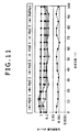
図9及び図10に示す検査装置56は、水状の流体70を用いることにより、ハイドロフォン20の加速度補正を効果的に決定することができる。前述したように、加速度相殺値は、検査ハイドロフォン20の出力及び標準加速度計68の出力を用いて、ハイドロフォン20の「真の」又は「絶対的な」加速度相殺値を得るために、算出されてもよい。図11及び図12にグラフで示すように、ハイドロフォンの加速度補正値は、大きく変化する可能性がある。図11は20Hzの駆動周波数における静水圧に対する、種々のハイドロフォン20の加速応答の例を示す。図12は80Hzの駆動周波数における類例を示す。異なる深さ、及び異なるハイドロフォンの種類において、加速応答は大幅に異なる可能性があるが、本発明の装置及び方法は、ハイドロフォンの加速度補正又は他のパラメータを測定するための、正確かつ繰り返し可能な技術を提供する。図11及び図12のグラフで参照される、10メートルずつの追加の深さが、約1バールの追加の静水圧に対応することに留意するべきである。
The
前述の利点と共に、検査装置56は大変可搬性があり、通常の、容易に用意できる、もしくは発注するのが簡単な実験室設備を用いて製造される場合がある。換言すれば、検査装置56は、関連リスクがごくわずか、又は全く無い典型的な実験環境で、容易に形成、使用、及び保持できる。
Along with the advantages described above, the
検査装置56は、検査されるハイドロフォン20の数及び圧力容器58内に生成される状態に応じて、種々の圧力容器58を組み込んでもよい。図13に、圧力容器58の1つの種類の一例を示す。この実施形態では、圧力室60は、2つのハイドロフォンのような、複数のハイドロフォン20,62を収容するのに十分に大きい。圧力容器58は、対応するエンドキャップ110との係合のために設計されたエンドコネクタ108を有する圧力ハウジング106をともなって形成される。例として、エンドコネクタ108はネジ部が、エンドキャップ110の対応するネジ部との係合のために螺刻されてもよい。
The
この実施形態では、圧力容器58は、個々の取付構造112が、対応するエンドコネクタ108及びエンドキャップ110の内部配置されるように配設された取付構造112を更に備えてもよい。各取付構造112は、圧力ハウジング106と密閉された係合を形成するための1つ以上のシール114を備えている。さらに、各取付構造112は、通信回線又は機能118の周囲を密閉するように配置された1つ以上のシール116を備えてもよい。通信回線又は機能118を通して、各ハイドロフォン20,62からのデータを、出力線72、及びプロセッサベースシステム78上へ中継する(図7〜図10参照)。しかしながら、示された圧力容器58は、単に圧力容器の一つの種類にすぎず、限定するものとして解釈されるべきではない。圧力容器58は、多くの種類の地震調査用途において用いられるための所望のハイドロフォン20の検査に順応する種々の特徴を有する種々の構成及びサイズで設計されてもよい。この地震調査は、海上油井基地上のボアホール地震調査、牽引されるアレイによる観測網調査、及び他の種類の地震調査を含む。
In this embodiment, the
前述のように、検査装置及び方法は、ハイドロフォン採用される条件を代表する加圧及び/又は他の条件下で、ハイドロフォンの1つ以上のパラメータを測定するために採用されてもよい。多くの種類の調査用途では、ハイドロフォンの加速度補正の測定は、地震調査から得られる地震データの正確な収集及び使用を容易にすることが望ましい。検査装置及び方法は、多くの種類の地震調査に用いるための多くの種類のハイドロフォンで使用されてもよい。 As mentioned above, the inspection apparatus and method may be employed to measure one or more parameters of the hydrophone under pressure and / or other conditions that are representative of the conditions employed by the hydrophone. For many types of survey applications, it is desirable that hydrophone acceleration correction measurements facilitate the accurate collection and use of seismic data obtained from seismic surveys. The inspection apparatus and method may be used with many types of hydrophones for use in many types of seismic surveys.
さらに、検査装置の特定の構成要素及び構成要素の配設は、検査用途に応じて異なってもよい。一部の実施形態では、検査装置56は、ある検査位置から別の位置に移動するために、車両上に容易に積み込める可搬機器として設計される。さらに、検査装置の種々の構成要素は、他の種類の構成要素と容易に置換及び/又は交換するために、モジュラーコンポーネントとして構築される。圧力容器はまた、特定の検査用途に所望されるように、異なる種類のハイドロフォン及び異なる数のハイドロフォンを収容するように設計されてもよい。
Furthermore, the specific components of the inspection device and the arrangement of the components may vary depending on the inspection application. In some embodiments, the
結果として、本発明のいくつかの実施形態のみを詳細に前述したが、本発明の教示から著しく逸脱することなく、多くの変更が可能であることを当業者は容易に理解するであろう。このような変更は、特許請求の範囲に定義させるように、本発明の範囲内に含まれるものとして意図される。 As a result, although only a few embodiments of the present invention have been described in detail above, those skilled in the art will readily appreciate that many variations are possible without significantly departing from the teachings of the present invention. Such modifications are intended to be included within the scope of the present invention as defined in the claims.
Claims (10)
振動源と、
前記振動源に接続され、流体媒体を収容する圧力容器と、
前記圧力容器内に取り付けられたハイドロフォンと、
前記振動源が作動し、かつ前記圧力容器が圧力下にある間に、前記ハイドロフォンの加速度相殺測定データを収集するために前記ハイドロフォンと通信可能に接続される、プロセッサと、を備える、装置。 A device for measuring acceleration cancellation characteristics of hydrophones,
A vibration source;
A pressure vessel connected to the vibration source and containing a fluid medium;
A hydrophone mounted in the pressure vessel;
A processor communicatively coupled with the hydrophone to collect acceleration cancellation measurement data of the hydrophone while the vibration source is activated and the pressure vessel is under pressure. .
振動源を起動することと、
ハイドロフォンを収容する、流体で満たされた容器を加圧することと、
前記振動源が前記圧力容器を動かしている間に前記ハイドロフォンのパラメータを測定することと、を含み、
パラメータを測定することは、ハイドロフォンの加速度相殺特性を測定することを含む、方法。 A method for measuring at least one parameter of a hydrophone, comprising:
Activating the vibration source;
Pressurizing a fluid-filled container containing a hydrophone;
Look including a measuring a parameter of the hydrophones while the vibration source is moving the pressure vessel,
Measuring the parameter includes measuring an acceleration cancellation characteristic of the hydrophone .
前記ハイドロフォンの絶対的な加速度相殺値を決定することと、
前記絶対的な加速度相殺値の標識を提供することと、を含み、
決定することは、圧力容器内に前記ハイドロフォンを配置することと、前記ハイドロフォンを振動させることと、前記ハイドロフォンを振動させている間に、プロセッサベースのシステムを利用して、前記ハイドロフォンの加速度相殺測定データを収集及び処理することとを含む、方法。 Selecting a hydrophone to evaluate;
Determining an absolute acceleration cancellation value of the hydrophone;
And providing an indication of the absolute acceleration offset value, only it contains,
Determining includes placing the hydrophone in a pressure vessel, vibrating the hydrophone, and utilizing the processor-based system while vibrating the hydrophone, Collecting and processing a plurality of acceleration cancellation measurement data .
Applications Claiming Priority (5)
| Application Number | Priority Date | Filing Date | Title |
|---|---|---|---|
| US26084109P | 2009-11-12 | 2009-11-12 | |
| US61/260,841 | 2009-11-12 | ||
| US12/912,745 | 2010-10-27 | ||
| US12/912,745 US8514655B2 (en) | 2009-11-12 | 2010-10-27 | Method and apparatus for measuring a hydrophone parameter |
| PCT/IB2010/002752 WO2011058403A2 (en) | 2009-11-12 | 2010-10-28 | Method and apparatus for measuring a hydrophone parameter |
Publications (3)
| Publication Number | Publication Date |
|---|---|
| JP2013511037A JP2013511037A (en) | 2013-03-28 |
| JP2013511037A5 JP2013511037A5 (en) | 2013-11-28 |
| JP5579865B2 true JP5579865B2 (en) | 2014-08-27 |
Family
ID=43974081
Family Applications (1)
| Application Number | Title | Priority Date | Filing Date |
|---|---|---|---|
| JP2012538422A Expired - Fee Related JP5579865B2 (en) | 2009-11-12 | 2010-10-28 | Method and apparatus for measuring hydrophone parameters |
Country Status (5)
| Country | Link |
|---|---|
| US (1) | US8514655B2 (en) |
| EP (1) | EP2486431A2 (en) |
| JP (1) | JP5579865B2 (en) |
| CA (1) | CA2779941A1 (en) |
| WO (1) | WO2011058403A2 (en) |
Families Citing this family (2)
| Publication number | Priority date | Publication date | Assignee | Title |
|---|---|---|---|---|
| FR3001301B1 (en) * | 2013-01-24 | 2015-08-07 | Cggveritas Services Sa | APPARATUS AND METHOD FOR DETERMINING FAR-DOMAIN SIGNATURE FOR A SEISMIC SEISMIC MARINE SOURCE |
| US11656375B2 (en) * | 2019-12-09 | 2023-05-23 | Magseis Ff Llc | Measuring hydrophone channel impedance using a test signal generator coupled in series |
Family Cites Families (21)
| Publication number | Priority date | Publication date | Assignee | Title |
|---|---|---|---|---|
| US3659255A (en) * | 1969-09-25 | 1972-04-25 | Winfield James Trott | Hydrophone calibrator |
| US5361240A (en) * | 1990-07-10 | 1994-11-01 | Innovative Transducers Inc. | Acoustic sensor |
| JPH04142485A (en) * | 1990-10-03 | 1992-05-15 | Tech Res & Dev Inst Of Japan Def Agency | Underwater sound receiver |
| US5285995A (en) * | 1992-05-14 | 1994-02-15 | Aura Systems, Inc. | Optical table active leveling and vibration cancellation system |
| US5367497A (en) * | 1993-08-12 | 1994-11-22 | Marschall Richard A | Extended frequency range hydrophone |
| US5448904A (en) * | 1994-05-11 | 1995-09-12 | The United States Of America As Represented By The Administrator Of The National Aeronautics And Space Administration | Acoustic calibration apparatus for calibrating plethysmographic acoustic pressure sensors |
| US5567863A (en) * | 1995-05-15 | 1996-10-22 | Larson-Davis, Inc. | Intensity acoustic calibrator |
| US5654937A (en) * | 1996-03-22 | 1997-08-05 | The United States Of America As Represented By The Secretary Of The Navy | Acoustic element tester for an array of hydrophones |
| US5712828A (en) * | 1996-08-20 | 1998-01-27 | Syntron, Inc. | Hydrophone group sensitivity tester |
| NL1004731C2 (en) * | 1996-12-09 | 1997-11-21 | Tno | Hydrophone with static pressure compensation and pressure measurement method. |
| WO2000055648A1 (en) * | 1999-03-17 | 2000-09-21 | Input/Output, Inc. | Hydrophone assembly |
| US6512980B1 (en) * | 1999-10-19 | 2003-01-28 | Westerngeco Llc | Noise reference sensor for use in a dual sensor towed streamer |
| US6381544B1 (en) * | 2000-07-19 | 2002-04-30 | Westerngeco, L.L.C. | Deterministic cancellation of air-coupled noise produced by surface seimic sources |
| FR2820820B1 (en) * | 2001-02-15 | 2004-04-16 | Commissariat Energie Atomique | DEVICE FOR CALIBRATING A PRESSURE SENSOR, IN PARTICULAR AN INFRASON PRESSURE SENSOR |
| US6583725B2 (en) * | 2001-07-13 | 2003-06-24 | William Fehrenkamp | Motion sensor |
| GB2428089B (en) * | 2005-07-05 | 2008-11-05 | Schlumberger Holdings | Borehole seismic acquisition system using pressure gradient sensors |
| US7551517B2 (en) * | 2006-05-05 | 2009-06-23 | Optoplan As | Seabed seismic station packaging |
| US8064286B2 (en) * | 2006-05-05 | 2011-11-22 | Optoplan As | Seismic streamer array |
| US7466625B2 (en) * | 2006-06-23 | 2008-12-16 | Westerngeco L.L.C. | Noise estimation in a vector sensing streamer |
| US7688674B2 (en) * | 2007-03-05 | 2010-03-30 | Schlumberger Technology Corporation | Methods and apparatus for performing moving checkshots |
| US9110187B2 (en) * | 2009-10-05 | 2015-08-18 | Westerngeco L.L.C. | Sensor assembly having a seismic sensor and a divergence sensor |
-
2010
- 2010-10-27 US US12/912,745 patent/US8514655B2/en not_active Expired - Fee Related
- 2010-10-28 CA CA2779941A patent/CA2779941A1/en not_active Abandoned
- 2010-10-28 EP EP10784843A patent/EP2486431A2/en not_active Withdrawn
- 2010-10-28 WO PCT/IB2010/002752 patent/WO2011058403A2/en active Application Filing
- 2010-10-28 JP JP2012538422A patent/JP5579865B2/en not_active Expired - Fee Related
Also Published As
| Publication number | Publication date |
|---|---|
| EP2486431A2 (en) | 2012-08-15 |
| CA2779941A1 (en) | 2011-05-19 |
| WO2011058403A3 (en) | 2011-07-07 |
| WO2011058403A2 (en) | 2011-05-19 |
| JP2013511037A (en) | 2013-03-28 |
| US20110110186A1 (en) | 2011-05-12 |
| US8514655B2 (en) | 2013-08-20 |
Similar Documents
| Publication | Publication Date | Title |
|---|---|---|
| US20110182140A1 (en) | Seismic system with ghost and motion rejection | |
| US20110085419A1 (en) | Sensor assembly having a seismic sensor, pressure sensor, and processor to apply first and second digital filters | |
| AU2011318229A1 (en) | An apparatus for and a method of characterising mechanical properties of a sample | |
| RU2678261C2 (en) | Seismic sensor with motion sensors for noise reduction | |
| US20090038397A1 (en) | Vibration sensor | |
| US20110153219A1 (en) | Direct velocity seismic sensing | |
| US10310121B2 (en) | Seismic sensor devices, systems, and methods including noise filtering | |
| Nedelec et al. | Best Practice Guide for Underwater Particle Motion Measurement for Biological Applications. | |
| WO1998041885A1 (en) | Underground acoustic wave transmitter, receiver, transmitting/receiving method, and underground exploration using this | |
| JP5579865B2 (en) | Method and apparatus for measuring hydrophone parameters | |
| Wang et al. | An experimental study on the excitation of large volume airguns in a small volume body of water | |
| Crawford et al. | Standard procedure for equipment performance, calibration and deployment | |
| RU2545159C1 (en) | Anchored profiling underwater observatory | |
| Osler et al. | Quantifying the interaction of an ocean bottom seismometer with the seabed | |
| AU2012294519B2 (en) | Method and apparatus for measuring seismic parameters of a seismic vibrator | |
| Trevorrow et al. | Very low frequency ocean bottom ambient seismic noise and coupling on the shallow continental shelf | |
| Jansen et al. | On the conversion between sound pressure and particle motion | |
| BR102017007562A2 (en) | CONTROL SYSTEM FOR A MARITIME VIBRATOR | |
| US20140283615A1 (en) | Determining a seismic vibrator signature | |
| Jansen et al. | Vector sensors and acoustic calibration procedures | |
| Robinson et al. | Standard procedure for equipment performance, calibration and deployment | |
| Roset et al. | Calibration and modelling of a bottom sea geophone based on virtual instrument | |
| Salimi | Pipe detection and remote condition monitoring using an in-pipe excitation technique | |
| Matsumoto et al. | Some characteristics of bottom pressure sensors of DONET | |
| Chen et al. | Development and preliminary application of a minimum axle-distance triaxial measurement system for the acoustic characteristics of marine sediments |
Legal Events
| Date | Code | Title | Description |
|---|---|---|---|
| A521 | Request for written amendment filed |
Free format text: JAPANESE INTERMEDIATE CODE: A523 Effective date: 20131009 |
|
| A621 | Written request for application examination |
Free format text: JAPANESE INTERMEDIATE CODE: A621 Effective date: 20131009 |
|
| A977 | Report on retrieval |
Free format text: JAPANESE INTERMEDIATE CODE: A971007 Effective date: 20140219 |
|
| A131 | Notification of reasons for refusal |
Free format text: JAPANESE INTERMEDIATE CODE: A131 Effective date: 20140312 |
|
| A521 | Request for written amendment filed |
Free format text: JAPANESE INTERMEDIATE CODE: A523 Effective date: 20140611 |
|
| TRDD | Decision of grant or rejection written | ||
| A01 | Written decision to grant a patent or to grant a registration (utility model) |
Free format text: JAPANESE INTERMEDIATE CODE: A01 Effective date: 20140702 |
|
| A61 | First payment of annual fees (during grant procedure) |
Free format text: JAPANESE INTERMEDIATE CODE: A61 Effective date: 20140709 |
|
| R150 | Certificate of patent or registration of utility model |
Ref document number: 5579865 Country of ref document: JP Free format text: JAPANESE INTERMEDIATE CODE: R150 |
|
| LAPS | Cancellation because of no payment of annual fees |