JP5579725B2 - Image processing method and apparatus for computer-assisted intraocular lens surgery, and program - Google Patents
Image processing method and apparatus for computer-assisted intraocular lens surgery, and program Download PDFInfo
- Publication number
- JP5579725B2 JP5579725B2 JP2011532614A JP2011532614A JP5579725B2 JP 5579725 B2 JP5579725 B2 JP 5579725B2 JP 2011532614 A JP2011532614 A JP 2011532614A JP 2011532614 A JP2011532614 A JP 2011532614A JP 5579725 B2 JP5579725 B2 JP 5579725B2
- Authority
- JP
- Japan
- Prior art keywords
- real
- image
- context information
- eye
- time image
- Prior art date
- Legal status (The legal status is an assumption and is not a legal conclusion. Google has not performed a legal analysis and makes no representation as to the accuracy of the status listed.)
- Active
Links
Images


Classifications
-
- A—HUMAN NECESSITIES
- A61—MEDICAL OR VETERINARY SCIENCE; HYGIENE
- A61F—FILTERS IMPLANTABLE INTO BLOOD VESSELS; PROSTHESES; DEVICES PROVIDING PATENCY TO, OR PREVENTING COLLAPSING OF, TUBULAR STRUCTURES OF THE BODY, e.g. STENTS; ORTHOPAEDIC, NURSING OR CONTRACEPTIVE DEVICES; FOMENTATION; TREATMENT OR PROTECTION OF EYES OR EARS; BANDAGES, DRESSINGS OR ABSORBENT PADS; FIRST-AID KITS
- A61F9/00—Methods or devices for treatment of the eyes; Devices for putting-in contact lenses; Devices to correct squinting; Apparatus to guide the blind; Protective devices for the eyes, carried on the body or in the hand
- A61F9/007—Methods or devices for eye surgery
- A61F9/00736—Instruments for removal of intra-ocular material or intra-ocular injection, e.g. cataract instruments
-
- A—HUMAN NECESSITIES
- A61—MEDICAL OR VETERINARY SCIENCE; HYGIENE
- A61B—DIAGNOSIS; SURGERY; IDENTIFICATION
- A61B3/00—Apparatus for testing the eyes; Instruments for examining the eyes
- A61B3/0016—Operational features thereof
- A61B3/0025—Operational features thereof characterised by electronic signal processing, e.g. eye models
-
- G—PHYSICS
- G06—COMPUTING; CALCULATING OR COUNTING
- G06T—IMAGE DATA PROCESSING OR GENERATION, IN GENERAL
- G06T7/00—Image analysis
- G06T7/0002—Inspection of images, e.g. flaw detection
- G06T7/0012—Biomedical image inspection
- G06T7/0014—Biomedical image inspection using an image reference approach
- G06T7/0016—Biomedical image inspection using an image reference approach involving temporal comparison
-
- G—PHYSICS
- G06—COMPUTING; CALCULATING OR COUNTING
- G06T—IMAGE DATA PROCESSING OR GENERATION, IN GENERAL
- G06T7/00—Image analysis
- G06T7/30—Determination of transform parameters for the alignment of images, i.e. image registration
-
- A—HUMAN NECESSITIES
- A61—MEDICAL OR VETERINARY SCIENCE; HYGIENE
- A61F—FILTERS IMPLANTABLE INTO BLOOD VESSELS; PROSTHESES; DEVICES PROVIDING PATENCY TO, OR PREVENTING COLLAPSING OF, TUBULAR STRUCTURES OF THE BODY, e.g. STENTS; ORTHOPAEDIC, NURSING OR CONTRACEPTIVE DEVICES; FOMENTATION; TREATMENT OR PROTECTION OF EYES OR EARS; BANDAGES, DRESSINGS OR ABSORBENT PADS; FIRST-AID KITS
- A61F2/00—Filters implantable into blood vessels; Prostheses, i.e. artificial substitutes or replacements for parts of the body; Appliances for connecting them with the body; Devices providing patency to, or preventing collapsing of, tubular structures of the body, e.g. stents
- A61F2/02—Prostheses implantable into the body
- A61F2/14—Eye parts, e.g. lenses, corneal implants; Implanting instruments specially adapted therefor; Artificial eyes
- A61F2/16—Intraocular lenses
- A61F2/1662—Instruments for inserting intraocular lenses into the eye
-
- A—HUMAN NECESSITIES
- A61—MEDICAL OR VETERINARY SCIENCE; HYGIENE
- A61F—FILTERS IMPLANTABLE INTO BLOOD VESSELS; PROSTHESES; DEVICES PROVIDING PATENCY TO, OR PREVENTING COLLAPSING OF, TUBULAR STRUCTURES OF THE BODY, e.g. STENTS; ORTHOPAEDIC, NURSING OR CONTRACEPTIVE DEVICES; FOMENTATION; TREATMENT OR PROTECTION OF EYES OR EARS; BANDAGES, DRESSINGS OR ABSORBENT PADS; FIRST-AID KITS
- A61F9/00—Methods or devices for treatment of the eyes; Devices for putting-in contact lenses; Devices to correct squinting; Apparatus to guide the blind; Protective devices for the eyes, carried on the body or in the hand
- A61F9/007—Methods or devices for eye surgery
- A61F9/008—Methods or devices for eye surgery using laser
- A61F2009/00844—Feedback systems
- A61F2009/00846—Eyetracking
-
- G—PHYSICS
- G06—COMPUTING; CALCULATING OR COUNTING
- G06T—IMAGE DATA PROCESSING OR GENERATION, IN GENERAL
- G06T2207/00—Indexing scheme for image analysis or image enhancement
- G06T2207/10—Image acquisition modality
- G06T2207/10016—Video; Image sequence
-
- G—PHYSICS
- G06—COMPUTING; CALCULATING OR COUNTING
- G06T—IMAGE DATA PROCESSING OR GENERATION, IN GENERAL
- G06T2207/00—Indexing scheme for image analysis or image enhancement
- G06T2207/30—Subject of image; Context of image processing
- G06T2207/30004—Biomedical image processing
- G06T2207/30041—Eye; Retina; Ophthalmic
Landscapes
- Engineering & Computer Science (AREA)
- Health & Medical Sciences (AREA)
- Life Sciences & Earth Sciences (AREA)
- Ophthalmology & Optometry (AREA)
- General Health & Medical Sciences (AREA)
- Physics & Mathematics (AREA)
- Animal Behavior & Ethology (AREA)
- Veterinary Medicine (AREA)
- Heart & Thoracic Surgery (AREA)
- Medical Informatics (AREA)
- Nuclear Medicine, Radiotherapy & Molecular Imaging (AREA)
- Surgery (AREA)
- Biomedical Technology (AREA)
- Public Health (AREA)
- Computer Vision & Pattern Recognition (AREA)
- General Physics & Mathematics (AREA)
- Theoretical Computer Science (AREA)
- Signal Processing (AREA)
- Biophysics (AREA)
- Molecular Biology (AREA)
- Radiology & Medical Imaging (AREA)
- Quality & Reliability (AREA)
- Vascular Medicine (AREA)
- Eye Examination Apparatus (AREA)
- Image Processing (AREA)
- Processing Or Creating Images (AREA)
Abstract
Description
本発明は、コンピューター支援眼内レンズ手術用の方法および装置に関し、詳しくは、眼の位置合わせおよび追跡を利用する眼内レンズ手術計画用の方法および装置ならびにプログラムに関する。 The present invention relates to a method and apparatus for computer-assisted intraocular lens surgery, and more particularly to a method and apparatus and program for intraocular lens surgery planning utilizing eye registration and tracking.
従来技術では、眼内レンズ(IOL)手術の工程は外科医にとって厄介な工程であった。従来技術による従来の工程には、4つのステップ、すなわちi)診断、ii)術前準備、iii)手術準備、iv)水晶体除去および移植、および最後にv)手術の仕上げが含まれるであろう。全工程を幾分詳しく以下に概説する。 In the prior art, the process of intraocular lens (IOL) surgery has been a cumbersome process for the surgeon. The conventional process according to the prior art will involve four steps: i) diagnosis, ii) preoperative preparation, iii) surgical preparation, iv) lens removal and implantation, and finally v) surgical finishing. . The overall process is outlined in some detail below.
第1ステップは、治療しようとする眼の診断に関する。通常、眼の形状(geometry)(長さ、眼房深度(chamber depth)、水晶体厚など)は、Zeiss社製IOL Masterのような器具を使用し決定する。それには、さらに、眼の角膜表面を測定するためのトポメトリ測定(topometrymeasurement)が含まれ得る。さらに、それには、眼の視覚性能を決定するための屈折計の使用が含まれ得る。この診断データを用いて、移植すべきIOL型およびIOL形状(geometry)を決定する。 The first step relates to the diagnosis of the eye to be treated. Usually, the eye geometry (length, chamber depth, lens thickness, etc.) is determined using a device such as IOL Master from Zeiss. It can further include a topometry measurement to measure the corneal surface of the eye. Further, it can include the use of a refractometer to determine the visual performance of the eye. This diagnostic data is used to determine the IOL type and IOL geometry to be transplanted.
第2ステップは、術前準備からなる。これは、「どこを切るか」など、その手術を「計画する」外科医が行う準備作業を意味する。これには、例えば、通常、ペンにより眼に基準垂直軸および水平軸をマーキングすることが含まれ得る。さらに、それには、ペンを使用し、診断画像のハードコピーに図形をマーキングすることも含まれ得る。 The second step consists of preoperative preparation. This means preparatory work performed by the surgeon “planning” the operation, such as “where to cut”. This can include, for example, marking the reference vertical and horizontal axes to the eye, usually with a pen. Furthermore, it may include using a pen to mark a graphic on a hard copy of the diagnostic image.
第3ステップは、手術準備からなる。手術準備には、例えば、麻酔、消毒および眼開瞼器が含まれる。手術にトーリックIOLが関与している場合、これには、後の最終的なIOLの向き(orientation)のために、マーキングペンまたは特殊な軸マーカー(Mendez Ring)で乱視軸をマーキングすることも関与する。 第3ステップには、さらに、機器用の、およびレンズを移植するための切開準備が含まれる。最後に、なめらかなレンズ移植を確実に行うために、眼に粘弾剤(viscoelastica)を注入する。 The third step consists of surgical preparation. Surgery preparation includes, for example, anesthesia, disinfection, and eyelid opener. If a toric IOL is involved in the surgery, this also involves marking the astigmatic axis with a marking pen or special axis marker (Mendez Ring) for later final IOL orientation. To do. The third step further includes preparation for the incision for the instrument and for implanting the lens. Finally, viscoelastica is injected into the eye to ensure smooth lens implantation.
第4ステップには、嚢切開、水流による解離(hydrodissection)、超音波乳化吸引、および当然、その後のレンズ移植など、実際の外科ステップが含まれる。 The fourth step includes actual surgical steps such as capsulotomy, hydrodissection, ultrasonic emulsification and, of course, subsequent lens implantation.
全手順の第5ステップは、手術の仕上げであり、この仕上げには、例えば、IOLの整合、トーリックIOLではIOLの角度位置の位置決め、および最後に粘弾剤の除去が含まれ得る。 The fifth step of the overall procedure is a surgical finish, which may include, for example, IOL alignment, IOL angular position positioning for toric IOLs, and finally viscoelastic removal.
全手順を概略的に図1に示す。これらのステップ、特に術前準備および手術準備が、コンピューターツールによるいかなる支援もなしに、外科医によって手作業で行われるのは注目すべきことである。例えば、視軸のマーキングには、実際の眼にペンでマークを付けるステップが含まれ、これは外科医には非常に単調な作業である。さらに、時間とともに、これらのマークは曖昧になり、または消え失せる可能性があり、手術の成績および精度に悪影響を及ぼしかねない。 The whole procedure is shown schematically in FIG. It should be noted that these steps, particularly pre-operative preparation and surgical preparation, are performed manually by the surgeon without any assistance from the computer tool. For example, visual axis marking includes the step of marking the actual eye with a pen, which is a very tedious task for the surgeon. Furthermore, over time, these marks can become ambiguous or disappear, which can adversely affect surgical performance and accuracy.
実際の手術中、外科医が得られるのは、手術用顕微鏡を通して見ることができるリアルタイム画像だけであり、手術を実施するのに助けとなり得る表示はそれ以上得られない。 During the actual surgery, the surgeon will only get real-time images that can be viewed through a surgical microscope, and no further indications that can help perform the surgery.
従って、外科医が前記ステップを実施する上で助けとなり得るツールを外科医に提供すること、特に手術の計画作り、さらに手術の実施の際に外科医を支援することによって、全工程を改善するのが望ましい。 It is therefore desirable to improve the overall process by providing the surgeon with tools that can help the surgeon in performing the steps, in particular, planning the surgery and assisting the surgeon in performing the surgery. .
一実施形態によれば、眼のコンピューター支援眼内レンズ手術用の画像処理装置で実行される画像処理方法であって、
前記装置で眼の基準画像を取得するステップ、
外科医にとって役立つ追加のコンテクスト情報であって、外科医が外科手術を実施すべき位置又は領域と、眼内レンズを設置する位置又は向きの少なくとも一つを図示するコンテクスト情報を前記装置内で挿入することによって、該基準画を充実させる(enrich)ステップ、
前記装置で眼のリアルタイム画像と該基準画像との位置合わせを行うステップ、および
眼の動きにかかわらず該コンテクスト情報が同じ位置に表示されるように、前記装置で眼の動きの追跡に基づいて、眼のリアルタイム画像に該コンテクスト情報を重ね合わせるステップ
を含む方法を提供する。
According to one embodiment, an image processing method performed by an image processing apparatus for computer assisted intraocular lens surgery of an eye, comprising:
Obtaining a reference image of the eye with the device ;
Inserting in the device additional context information useful for the surgeon, which illustrates at least one of the location or area where the surgeon is to perform the surgery and the location or orientation where the intraocular lens is to be placed Step to enrich the reference image,
Aligning the real-time image of the eye with the reference image at the device, and based on tracking eye movement at the device so that the context information is displayed at the same position regardless of eye movement. And superimposing the context information on a real-time image of the eye.
このようにして、外科医を支援する画像処理を実施することによって、手術中に外科医を支援するだけでなく、手術計画中も支援する。 In this way, by performing image processing to assist the surgeon, not only is the surgeon supported during surgery, but also during surgical planning.
一実施形態によれば、前記方法はさらに、
前記基準画像の眼の1個以上の特徴に基づく座標系決定アルゴリズムを使用し第1座標系を決定するステップ、
該座標系に基づき前記コンテクスト情報の空間位置を決定するステップ、
該座標系決定アルゴリズムを使用し手術中に撮影したリアルタイム画像での第2座標系を決定するステップ、
該第1座標系から該第2座標系への座標変換を確定することによって、該コンテクスト情報を重ね合わせる位置を決定するステップ
を含む。
According to one embodiment, the method further comprises:
Determining a first coordinate system using a coordinate system determination algorithm based on one or more features of the eye of the reference image;
Determining a spatial position of the context information based on the coordinate system;
Determining a second coordinate system in a real-time image taken during surgery using the coordinate system determination algorithm;
Determining a position to superimpose the context information by determining a coordinate transformation from the first coordinate system to the second coordinate system.
このようにして、基準画像の新たに決定された座標系でのコンテクスト情報の絶対的空間位置を決定することができる。次いで、この位置を後で使用して、手術中に、リアルタイム画像中の同じ位置にコンテクスト情報を正確に配置することができる。 In this way, the absolute spatial position of the context information in the newly determined coordinate system of the reference image can be determined. This location can then be used later to accurately place the context information at the same location in the real-time image during surgery.
一実施形態によれば、前記方法は、
リアルタイム画像配列の初期画像と前記基準画像の位置合わせを行い、初期座標変換を取得するステップ、
さらなるリアルタイム画像とリアルタイム画像配列の初期画像の比較に基づいて眼の動きを追跡して第2座標変換を取得し、そして該第1座標変換と該第2座標変換の組合せに基づき、該基準画像から該リアルタイム画像配列のリアルタイム画像への最終座標変換を取得し、該組み合わせられた座標変換に基づき該リアルタイム画像に該コンテクスト情報を表示できるようにするステップ、または
リアルタイム画像配列のリアルタイム画像と該基準画像の位置合わせを行い、該基準画像から該リアルタイム画像配列のリアルタイム画像への座標変換を取得し、得られた該座標変換に基づいて該リアルタイム画像に該コンテクスト情報を表示できるようにするステップ
を含む。
According to one embodiment, the method comprises:
Aligning the initial image of the real-time image array with the reference image and obtaining an initial coordinate transformation;
Tracking a movement of the eye based on a comparison of the further real-time image and an initial image of the real-time image array to obtain a second coordinate transformation, and based on a combination of the first coordinate transformation and the second coordinate transformation, the reference image Obtaining a final coordinate transformation from the real-time image sequence to a real-time image and allowing the context information to be displayed in the real-time image based on the combined coordinate transformation, or the real-time image and the reference in the real-time image sequence Aligning the images, obtaining a coordinate transformation from the reference image to the real-time image of the real-time image array, and allowing the context information to be displayed on the real-time image based on the obtained coordinate transformation. Including.
第1の代替策は、リアルタイム画像配列の初期画像を使用し、初期画像と基準画像との間の位置合わせを行った。これは、第1座標変換をもたらす。次いで、初期画像から出発してリアルタイム画像の追跡が行われ、第2座標変換を取得する。両変換を組み合わせることによって、基準画像とリアル画像配列のリアルタイム画像の差異に相当する変換が得られる。 The first alternative used an initial image of the real-time image array and performed an alignment between the initial image and the reference image. This results in a first coordinate transformation. Then, starting from the initial image, real time image tracking is performed to obtain a second coordinate transformation. By combining both conversions, a conversion corresponding to the difference between the reference image and the real-time image in the real image array can be obtained.
あるいは、基準画像とリアルタイム画像配列のリアルタイム画像の間の位置合わせを直接行うことも可能であり、これは、計算コストがより高くなるであろう。 Alternatively, registration between the reference image and the real-time image of the real-time image array can be done directly, which will be more computationally expensive.
一実施形態によれば、前記コンテクスト情報は、
診断目的に有用である眼の特性またはパラメーターである、眼のトポメトリデータまたは波面データを図示する診断データを含む。
重ね合わせできる手術計画データは、外科医が正しい場所で正しい手術を実施するのに大きな助けとなる。同様にまた、波面データまたはトポメトリ(topometry)データなどの診断情報の重ね合わせは、手術中大変な助けとなり得る。
According to one embodiment, the context information is:
It includes diagnostic data illustrating ocular topometry data or wavefront data , which are ocular characteristics or parameters that are useful for diagnostic purposes.
Surgical plan data that can be overlaid helps the surgeon to perform the right surgery at the right place. Similarly, overlaying diagnostic information such as wavefront data or topometry data can be a great help during surgery.
一実施形態によれば、リアルタイムの眼の画像上でコンテクスト情報が重ね合わされる位置が、そのコンテクスト情報が基準画像に加えられた位置と同じ位置である。 According to one embodiment, the position where the context information is superimposed on the real-time eye image is the same position as the position where the context information was added to the reference image.
外科医が、例えば切開を行う正確な位置に切開マークを表示させたい場合、これは役立つ。 This is useful if the surgeon wants to display an incision mark at the exact location where the incision is made, for example.
一実施形態によれば、前記リアルタイム画像上の前記コンテクスト情報の重ね合わせは、外科医によってオン・オフが切り替えられる。 According to one embodiment, the superposition of the context information on the real-time image is switched on and off by a surgeon.
これにより、外科医は、所望により又都合により、コンテクスト情報の重ね合わせと除去ができるようになる。 This allows the surgeon to superimpose and remove context information as desired and convenient.
一実施形態によれば、前記コンテクスト情報は、
切開を行った位置をマーキングするための1個以上の切開マーク、
トーリック眼内レンズを置くための円柱軸、
器具を固定するための、例えば有水晶体眼内レンズ用の1個以上のアンカー領域、
例えば、正しい位置に有水晶体眼内レンズを置くための瞳孔マークまたは視線マーク、
角膜インレーまたは角膜アンレーの位置
の1個以上を含むものである。
According to one embodiment, the context information is:
One or more incision marks for marking the location of the incision;
Cylindrical axis for placing toric intraocular lens,
One or more anchor regions, eg for phakic intraocular lenses, for securing the instrument;
For example, the pupil mark or line-of-sight marks order to put the phakic intraocular lens in position,
Position of corneal inlay or corneal onlay
1 or more.
これらは、特段の有利なやり方で本発明の操作原理を適用できる使用例である。 These are examples of uses where the operating principle of the invention can be applied in a particularly advantageous manner.
一実施形態によれば、眼のコンピューター支援眼内レンズ手術用の画像処理装置を提供し、当該装置は、
眼の基準画像を取得するモジュール、
眼の手術を実施する際に外科医にとって役立つ追加のコンテクスト情報であって、外科医が外科手術を実施すべき位置又は領域と、眼内レンズを設置する位置又は向きの少なくとも一つを図示するコンテクスト情報を挿入することによって、該基準画像を充実させるモジュール、
眼のリアルタイム画像と該基準画像との位置合わせを行うモジュール、および
眼の動きにかかわらず該コンテクスト情報が同じ位置に表示されるように、眼の動きの追跡に基づいて眼のリアルタイム画像に該コンテクスト情報を重ね合わせるモジュール
を含む。
According to one embodiment, an image processing device for computer assisted intraocular lens surgery of the eye is provided, the device comprising:
A module for acquiring a reference image of the eye,
Additional context information useful to the surgeon when performing eye surgery, the context information illustrating at least one of the location or area where the surgeon should perform the surgery and the location or orientation where the intraocular lens is to be placed A module that enhances the reference image by inserting
A module that aligns the real-time image of the eye with the reference image, and the real-time image of the eye based on tracking of eye movement so that the context information is displayed at the same position regardless of eye movement. Includes modules that superimpose context information.
このようにして、本発明の実施形態による装置を実施することができる。 In this way, an apparatus according to an embodiment of the present invention can be implemented.
一実施形態によれば、その装置はさらに、
前記基準画像の眼の1個以上の特徴に基づく座標系決定アルゴリズムを使用し第1座標系を決定するモジュール、
該座標系に基づき前記コンテクスト情報の空間位置を決定するモジュール、
該座標系決定アルゴリズムを使用し手術中に撮影したリアルタイム画像での第2座標系を決定するモジュール、
該第1座標系から該第2座標系への座標変換を確定することによって、該コンテクスト情報を重ね合わせる位置を決定するモジュール
を含む。
According to one embodiment, the device further comprises:
A module for determining a first coordinate system using a coordinate system determination algorithm based on one or more features of the eye of the reference image;
A module for determining a spatial position of the context information based on the coordinate system;
A module for determining a second coordinate system in a real-time image taken during surgery using the coordinate system determination algorithm;
A module for determining a position to superimpose the context information by determining a coordinate transformation from the first coordinate system to the second coordinate system;
一実施形態によれば、前記コンテクスト情報は、
診断目的に有用である眼の特性またはパラメーターである、トポメトリデータまたは波面データを図示する診断データを含むものである。
According to one embodiment, the context information is:
It includes diagnostic data illustrating topometry data or wavefront data , which are ocular characteristics or parameters that are useful for diagnostic purposes .
一実施形態によれば、リアルタイムの眼の画像上でコンテクスト情報が重ね合わされる位置は、そのコンテクスト情報が基準画像に加えられた位置と同じである。 According to one embodiment, the position where the context information is superimposed on the real-time eye image is the same as the position where the context information was added to the reference image.
一実施形態によれば、前記リアルタイム画像上の前記コンテクスト情報の重ね合わせは、外科医によってオン・オフの切り替えができる。 According to one embodiment, the superposition of the context information on the real-time image can be switched on and off by a surgeon.
一実施形態によれば、前記コンテクスト情報は、
切開を行った位置をマーキングするための1個以上の切開マーク、
トーリック眼内レンズを置くための円柱軸、
器具を固定するための、例えば有水晶体眼内レンズ用の1個以上のアンカー領域、
例えば、正しい位置に有水晶体眼内レンズを置くための、瞳孔マークまたは視線マーク、角膜インレーまたは角膜アンレーの位置
の1個以上を含むものである。
According to one embodiment, the context information is:
One or more incision marks for marking the location of the incision;
Cylindrical axis for placing toric intraocular lens,
One or more anchor regions, eg for phakic intraocular lenses, for securing the instrument;
For example, the position of the pupil or line of sight , corneal inlay or corneal onlay to place the phakic intraocular lens in the correct position
1 or more.
一実施形態によれば、コンピューターで実行したとき、前記コンピューターが本発明の実施形態の1つによる方法を実施できるようにするコンピュータープログラムコードを含むコンピュータープログラムが提供される。 According to one embodiment, a computer program is provided that includes computer program code that, when executed on a computer, enables the computer to perform a method according to one of the embodiments of the present invention.
一実施形態によれば、患者の眼の診断および術前計画の結果と外科医の顕微鏡下の患者の眼とを直接関連付けることによって、眼内レンズの手術工程の改善を達成する装置が提供される。 According to one embodiment, an apparatus is provided that achieves an improved intraocular lens surgical process by directly associating the results of a patient's eye diagnosis and preoperative planning with the patient's eye under a surgeon's microscope. .
これにより、従来の「手作業による」工程と比較して顕著な利点がもたらされる。いくつかの利点を以下に列挙する。 This provides significant advantages over conventional “manual” processes. Some advantages are listed below.
− 全工程のスピードアップおよび単純化:IOL工程、特にトーリックIOLの工程で時間がかかるインクマーカーおよびスタンプツールはもはや不要になる。
− 工程精度:エラーが生じやすいマーカーおよびプリントアウト技法が回避される。
− 工程の安全性:手術前の外科医の綿密な計画及び診断とIOL手術間の一致した座標により、工程の誤りによる異常値数を減少させることができる。
-Speeding up and simplifying the whole process: Ink markers and stamp tools that are time consuming in the IOL process, especially the toric IOL process, are no longer needed.
-Process accuracy: avoid error-prone markers and printout techniques.
-Process safety: Precise surgeon thorough planning and diagnosis and consistent coordinates between IOL surgery can reduce the number of outliers due to process errors.
既に上で説明したように、従来のIOL手術工程は、治療しようとする眼の診断から開始する。通常、IOL Master(例えばZeiss社製医療器具)を使用し、眼の形状(長さ、眼房深度、水晶体厚など)を決定する。さらに、予め眼のトポメトリおよび屈折を決定することが多い。この診断データを使用して、移植すべきIOL型およびIOL形状を決定する。 As already explained above, the conventional IOL surgical process starts with the diagnosis of the eye to be treated. Usually, an IOL Master (for example, a medical device manufactured by Zeiss) is used to determine an eye shape (length, chamber depth, lens thickness, etc.). In addition, the topometry and refraction of the eye are often determined in advance. This diagnostic data is used to determine the IOL type and IOL shape to be implanted.
以下において、外科医がIOL手術を実施する工程を支援する本発明の実施形態を説明する。図2を参照して、外科医を支援できるそのような器具の操作を説明する。まず、眼の画像200を取得するが、この画像は診断に使用することができ、次いで特に、手術のさらなる手順で基準画像として使用される。そのようにして取得した基準画像を使用し、いくつかのグラフィック操作ツールまたは画像処理ツールによって、例えば、その画像に1つ以上の位置または領域をマーキングする等、外科医は、基準画像にコンテクスト情報210を挿入、または基準画像にコンテクスト情報を付加することができる。その結果、後に実際の手術を実施する際に外科医にとって有用または有益ないくつかのコンテクスト情報によって、基準画像が「充実した」ものになる。
さらに、いくつかのコンテクスト情報を挿入することによって、基準画像の座標系と、コンテクスト情報が位置する座標との間の関係が定義される。すなわち、例えば、基準画像中のある一点または一領域をマーキングすることによって、そのような点または領域の座標が、基準画像の座標系に関して(または、基準画像中のある種の固定点に関して)固定される。これは、コンテクスト情報を加えることによってコンテクスト情報が位置する、基準画像中の位置(すなわち、基準画像の座標系中のコンテクスト情報の座標)の定義が確立されることを意味する。
In the following, embodiments of the present invention are described that assist the surgeon in performing the IOL procedure. With reference to FIG. 2, the operation of such an instrument capable of assisting the surgeon will be described. First, an
Further, by inserting some context information, the relationship between the coordinate system of the reference image and the coordinates where the context information is located is defined. That is, for example, by marking a point or region in the reference image, the coordinates of such point or region are fixed with respect to the coordinate system of the reference image (or with respect to certain fixed points in the reference image). Is done. This means that by adding the context information, the definition of the position in the reference image (that is, the coordinates of the context information in the coordinate system of the reference image) where the context information is located is established.
コンテクスト情報の挿入または付加の結果として、基準画像はこの追加の情報(コンテクスト情報)を含み、2成分を有するとみなしてよい。第1成分は、取得した実際の基準画像であり、第2成分は、追加のコンテクスト情報(基準画像中の位置、または基準画像に対する位置を含む)である。図2で概略的に示すコンテクスト情報210は、例えば、手術中に切開すべき場所を外科医に示すマーカーであり得る。
As a result of the insertion or addition of context information, the reference image may include this additional information (context information) and be considered to have two components. The first component is the acquired actual reference image, and the second component is additional context information (including a position in the reference image or a position relative to the reference image). The
一実施形態によれば、コンテクスト情報は、基準画像とは別に、例えば、別のファイルまたはデータセットとして保存し処理される。これにより、例えば(さらに詳細に後述するように)手術中にリアルタイム画像にコンテクスト情報のみを重ね合わせたい場合、元の基準画像とコンテクスト情報を別々に維持することができる。さらに、コンテクスト情報を基準画像(または「診断画像」)とは別に保存し処理する場合、コンテクスト情報には基準画像中のコンテクスト情報の位置についての情報が含まれ、その結果、その後いつでも、後の段階で基準画像中にまたは手術中のリアルタイム画像中に、コンテクスト情報を「挿入」できるようになる。後でさらに詳細に説明するように、後者の場合は次いで位置合わせおよび追跡に基づく追加の座標変換を含み得る。 According to one embodiment, the context information is stored and processed separately from the reference image, for example, as a separate file or data set. Thereby, for example (as will be described in more detail later), when only context information is to be superimposed on a real-time image during surgery, the original reference image and context information can be maintained separately. In addition, when context information is stored and processed separately from the reference image (or “diagnostic image”), the context information includes information about the position of the context information in the reference image, so that at any time thereafter Context information can be “inserted” into a reference image or a real-time image during surgery at a stage. As will be described in more detail later, the latter case may then include additional coordinate transformations based on registration and tracking.
コンテクスト情報を定義する前に、操作には基準画像での座標系の定義が含まれ得る。これは、座標系が、後で取得する別の画像でも同様の座標系が再度その原点が眼の中の同じ位置にあり、かつ基準画像用に決定した座標系の場合と同じ向き(orientation)を有するように定義されることを意味する。この目的のために、眼の固定点、あるいは時とともに変化しない(または、それほど変化しない)眼の特徴、例えば角膜縁(limbus)または強膜血管のような眼の特徴などを使用し、座標系を決定してもよい。これらの特徴を参照することによって、手作業でまたは自動的に、座標系の原点を定義または決定できるであろうが、いかなる場合でも、その後に再度、眼の中の同じ位置に座標系を定める(または、見つける)ことができるように行う。後でさらに詳細に説明するように、基準画像中の座標系とリアルタイム画像(または、リアルタイム画像配列の初期画像)中の同じ座標系の位置を比較することで、一座標系を他方の座標系と一致するように移行させるのに適用する必要のある座標変換を確定することができる。 Prior to defining the context information, the operation may include defining a coordinate system in the reference image. This is the same orientation as in the case where the coordinate system is another image acquired later, and the same coordinate system has its origin at the same position in the eye and is determined for the reference image. Is defined as having For this purpose, a coordinate system is used that uses fixed points of the eye or eye features that do not change (or change so little) over time, such as eye features such as limbus or scleral blood vessels. May be determined. By referring to these features, the origin of the coordinate system could be defined or determined manually or automatically, but in any case, the coordinate system is then re-determined at the same position in the eye Do (or find out) as you can. As described in more detail later, by comparing the position of the coordinate system in the reference image and the same coordinate system in the real-time image (or the initial image of the real-time image array), one coordinate system is replaced with the other coordinate system. The coordinate transformations that need to be applied to transition to match can be determined.
コンテクスト情報(および基準画像の座標系でのその位置)を定義した後、次いで装置の操作は、カメラによって「生(ライブ)で」撮影した患者の実際のリアルタイム画像215と診断画像または基準画像220との位置合わせを行うことによってさらに進行する。
After defining the context information (and its position in the reference image's coordinate system), the operation of the device is then followed by the actual real-
位置合わせ(registration)工程は、基準画像を患者の実際のライブ画像215(または、ある時刻の選択された実際のライブ画像)と合致するように「移行」させるのに必要な座標変換が確定されるという効果を有する。位置合わせ(およびそこから得られた座標変換パラメーター)を利用し、次いで、基準画像に追加された「コンテクスト情報」の座標変換を実施することができ、その結果、次の操作ステップで、患者の眼の実際のリアルタイム画像にコンテクスト情報を重ね合わせることができる。従来技術による眼の追跡メカニズムの使用によって、コンテクスト情報を含むこの重ね合わせ画像は、眼の動きと共にリアルタイムで「追跡」することができ、その結果、ついで外科医は、いつでもモニター上に、手術の実施(または計画)を支援することが可能な追加のコンテクスト情報を重ね合わせた眼のリアルタイム画像を出せる。 The registration process establishes the coordinate transformation required to “translate” the reference image to match the patient's actual live image 215 (or the selected actual live image at a certain time). Has the effect of Using the alignment (and the resulting coordinate transformation parameters), then a coordinate transformation of the “context information” added to the reference image can be performed, so that in the next operational step, the patient's Context information can be superimposed on the actual real-time image of the eye. Through the use of prior art eye tracking mechanisms, this overlay image containing context information can be “tracked” in real time along with eye movement, so that the surgeon can then perform the surgery on the monitor at any time. A real-time image of the eye superimposed with additional context information that can support (or planning).
従って、まず、基準座標系の初期移行としての位置合わせを、座標変換z1により、ある時刻のtで選択した眼のリアルタイム画像と合致するように行い、次いでtより後の時刻用に、各時刻でさらなる座標変換z2を確定し、この第2変換z2により、tより後の時刻でのその眼の動きを補正する。2個の座標変換z1およびz2によって眼の動き補正が可能になり、眼の動きにもかかわらず、コンテクスト情報をリアルタイムの眼の画像のある固定位置に重ね合わせできるようになる。 Therefore, first, alignment as an initial transition of the reference coordinate system is performed by coordinate transformation z1 so as to match the real-time image of the eye selected at t at a certain time, and then for each time after t Then, a further coordinate transformation z2 is determined, and the movement of the eye at a time later than t is corrected by the second transformation z2. The two coordinate transformations z1 and z2 enable eye movement correction, and context information can be superimposed on a fixed position of a real-time eye image regardless of the eye movement.
図2に関連して先に説明した操作を行うための装置を概略的に図3に示す。(看護士が操作するであろう)診断器具には、診断カメラ(または基準画像カメラ)が含まれ、この診断カメラは診断画像または基準画像を取得する。 An apparatus for performing the operations described above in connection with FIG. 2 is schematically shown in FIG. The diagnostic instrument (which the nurse will operate) includes a diagnostic camera (or reference image camera) that acquires a diagnostic image or reference image.
画像はコンピューター(PCなど)に保存され処理され、そしてコンピューターは、取得した基準画像をコンテクスト情報で充実させるために、すなわち基準画像にコンテクスト情報を「付加」、またはコンテクスト情報を「定義」するために、使用者がグラフィック操作またはグラフィック画像処理を行えるようにする処理を行う。コンテクスト情報は、手術実施中外科医を支援する任意の情報であり得る。特に、これには、手術の計画(次いで実施)に有用なマークが含まれ、または診断情報も含まれよう。 The image is stored and processed on a computer (such as a PC), and the computer either enriches the acquired reference image with context information, ie “adds” context information to the reference image or “defines” context information. In addition, processing is performed to allow the user to perform graphic operations or graphic image processing. Context information can be any information that assists the surgeon during the procedure. In particular, this will include marks useful for surgical planning (and then performing) or diagnostic information.
コンテクスト情報を付加するために、スクリーンまたはタッチスクリーンを含み得る「計画用モニター」を提供するが、医師は、そのモニター上でグラフィック操作ツールにより、例えば、マーキングすべき基準画像中の1つ以上の位置または領域を選択することによって、コンテクスト情報を挿入(または付加または定義)でき、その結果、コンテクスト情報で充実した基準画像が得られる。外科医は、例えば単に点または領域を選択することができ、そしてこのようにしてコンテクスト情報を表示すべき眼の中の位置を定義しうる。 In order to add context information, a “planning monitor” is provided that may include a screen or a touch screen, but the physician uses a graphical manipulation tool on the monitor, eg, one or more in a reference image to be marked. By selecting a position or region, context information can be inserted (or added or defined), resulting in a reference image enriched with context information. The surgeon can, for example, simply select a point or region and thus define the position in the eye where the context information should be displayed.
実際には、充実した基準画像を生成するのに好適なグラフィック処理を実行するコンピューターからなる「手術プランナー」の成果は、コンテクスト情報によって充実した基準画像または診断画像である。別の実施形態では、それは、コンテクスト情報を含む別のデータセットまたはファイルであり、そのコンテクスト情報には、コンテクスト情報が位置する眼の1つ以上の位置の定義が含まれる。コンテクスト情報は、その位置に加え、選択した対応する位置を示す単なる1ビットかもしれない実際のコンテクスト情報をさらに含むかもしれず、または、表示すべきカラーまたはスタイル(破線または非破線など)等のより詳細な情報を含むかもしれない。 In practice, the result of a “surgical planner” consisting of a computer that executes graphic processing suitable for generating a full reference image is a reference image or a diagnostic image that is enriched by context information. In another embodiment, it is another data set or file that includes context information that includes a definition of one or more positions of the eye in which the context information is located. The context information may further include the actual context information that may be just one bit indicating the selected corresponding position in addition to its position, or more such as the color or style to be displayed (such as dashed or non-dashed) May contain detailed information.
次いで、そのように充実した基準画像を処理ユニット(これは又PCであってよく、一実施形態によれば、手術プランナーも形成するPCであってもよい)に入力するが、このユニットは眼のリアルタイム画像(ライブ画像)と基準画像の位置合わせを行い、次いでさらにライブ画像の追跡も行う。その目的に向けて、手術用顕微鏡が設けられ、カメラにより患者の眼の画像を取得する。患者の目の画像に基づき、かつさらに、充実した基準画像に基づき、処理ユニットにより位置合わせおよび追跡を実施する。 Such a solid reference image is then input to a processing unit (which may also be a PC, and according to one embodiment may be a PC that also forms a surgical planner), which unit is the eye. The real-time image (live image) and the reference image are aligned, and then the live image is also tracked. To that end, a surgical microscope is provided, and an image of the patient's eye is acquired by a camera. Registration and tracking is performed by the processing unit based on the patient's eye image and further based on the rich reference image.
一実施形態では、コンテクスト情報は別のファイルに保存され、その後、「純粋」基準画像を使用して位置合わせが行われた後だけに使用されると仮定して、充実する前の基準画像に基づいて位置合わせを行うことも可能である。 In one embodiment, it is assumed that the context information is stored in a separate file and then used only after registration using a “pure” reference image, to the pre-filled reference image. It is also possible to perform alignment based on this.
次いで、追加ユニットである「重ね合わせ」ユニットを提供する。この重ね合わせユニットもまた、PCによって、または位置合わせおよび追跡を実施する処理ユニットのモジュールによって実施し得る。重ね合わせユニットは、患者の眼のライブ画像にコンテクスト情報を「重ね合わせる」動作を実行する。その目的で、重ね合わせユニットから、位置合わせ工程により得られ、そして基準画像がライブ画像と合致するように行う必要がある位置の移行(シフト)を示す座標変換データを参照する。次いで、この座標変換をコンテクスト情報に適用することで、このコンテクスト情報を眼のリアルタイムライブ画像中に表示することができる。この結果が重ね合わせであり、コンテクスト情報の付加ステップ中に基準画像に付加された追加のコンテクスト情報が、眼のリアルタイム画像に重ね合わされている。(原理的には当技術分野で公知の)眼の追跡メカニズムを適用することによって、重ね合わせ部(追加コンテクスト情報)は眼の動きを追うことができ、その結果、眼の動きにもかかわらず、そのコンテクスト情報は、計画段階中に付加された位置と常に同じ位置に重ね合わされる。 Then, an “overlapping” unit, which is an additional unit, is provided. This superposition unit may also be implemented by a PC or by a module of a processing unit that performs alignment and tracking. The superposition unit performs an operation of “superimposing” context information on the live image of the patient's eye. To that end, reference is made to the coordinate transformation data obtained from the registration unit by the registration process and indicating the position shift (shift) that needs to be done so that the reference image matches the live image. Then, by applying this coordinate transformation to the context information, this context information can be displayed in the real-time live image of the eye. This result is superposition, and the additional context information added to the reference image during the context information addition step is superimposed on the real-time image of the eye. By applying an eye tracking mechanism (in principle known in the art), the overlay (additional context information) can follow the eye movement and, as a result, despite eye movement. The context information is always superimposed at the same position as the position added during the planning stage.
その結果、(「重ね合わせモニター」として図3に示す)コンピューターに接続したスクリーン上で、医師は、ライブ画像に重ね合わされ、眼の動きを追って、一実施形態では、基準画像に付加された実際の位置である、ライブ画像の同じ位置に常に表示されるコンテクスト情報によって充実したライブ画像を見ることができる。 As a result, on a screen connected to a computer (shown in FIG. 3 as a “superimposition monitor”), the physician superimposes the live image and follows the movement of the eye, in one embodiment, the actual image added to the reference image. A rich live image can be seen by the context information always displayed at the same position of the live image, which is the position of.
以下において、IOL手術に位置合わせおよび追跡を利用して、標準的眼内レンズ手術ワークフローをどのように顕著に改善することができるかを示す、いくつかの別の実施形態を幾分さらに詳細に説明する。 In the following, some additional embodiments will be described in somewhat more detail, showing how registration and tracking can be utilized for IOL surgery to significantly improve the standard intraocular lens surgery workflow. explain.
以下に記載する一実施形態によれば、IOL手術用の切開計画ツールが提供される。 According to one embodiment described below, an incision planning tool for IOL surgery is provided.
あらゆるIOL手術で、例えば、存在する水晶体の除去し、折り畳まれたIOLを誘導し、IOLの位置を決め、一時的な液体を導入および除去するために、医師は、眼に複数のカット(=切開)を入れて、角膜下に手術ツールを入れなければならない。切開は、角膜中の角膜縁境界付近または強膜領域中に入れる。角膜の物理的挙動、および切開の位置により、角膜に数ディオプターまでの乱視を誘発させることができる。このよく知られた効果は、正しい切開位置を選ぶことによって既存の乱視を補正するために通常利用される。不正確な位置での切開は、さらなる乱視または乱視補正の低下、従って患者にとって視力の低下をもたらす恐れがある。切開計画はいくつかの方法に基づいており、全て主として角膜のトポメトリに基づいている。 In every IOL surgery, for example, to remove the existing lens, guide the folded IOL, position the IOL, and introduce and remove temporary fluid, the physician may make multiple cuts (= An incision) must be made and a surgical tool must be placed under the cornea. An incision is made near the corneal border boundary in the cornea or in the scleral region. Depending on the physical behavior of the cornea and the location of the incision, the cornea can induce astigmatism up to several diopters. This well-known effect is usually used to correct existing astigmatism by choosing the correct incision position. An incision at an inaccurate location can lead to further astigmatism or diminished astigmatism correction, thus reducing vision for the patient. The incision plan is based on several methods, all based primarily on corneal topometry.
IOL手術用の位置合わせおよび追跡を利用して、中間的手術計画ステップを導入することができ、その際、医師は、診断データの受け取り後で手術前に、患者にとって最も適合する切開を計画する。切開は、視覚的コンテクスト情報として、診断画像にタグを付け標識することができる。IOL手術用の位置合わせを利用し、診断画像の眼の座標系を手術時の眼の座標系に合わせる。IOL手術用の追跡を利用し、手術中、眼の座標系は、診断用の眼の座標系と一貫して合致する。この方式で、医師は、現在の手術用顕微鏡画像の上に、手術計画ステップで加えた視覚的コンテクスト情報を重ね合わせることができる。 Alignment and tracking for IOL surgery can be utilized to introduce an intermediate surgery planning step, where the physician plans the incision that best fits the patient after receiving diagnostic data and before surgery . The incision can tag and mark the diagnostic image as visual context information. Using the alignment for IOL surgery, the eye coordinate system of the diagnostic image is matched to the eye coordinate system at the time of surgery. Utilizing IOL surgical tracking, the eye coordinate system consistently matches the diagnostic eye coordinate system during surgery. In this manner, the doctor can superimpose the visual context information added in the surgical planning step on the current surgical microscope image.
ここで、コンテクスト情報を加えた基準画像は、眼の「純粋な」画像であってもよく、またはトポメトリ情報などの追加の情報を含み得る診断画像であってもよいことに留意されたい。 It should be noted here that the reference image plus the context information may be a “pure” image of the eye or may be a diagnostic image that may contain additional information such as topometry information.
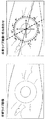
図4は、重ね合わせた切開マーカーがある眼の画像を概略的に図示する。このマーカーは、計画立案段階中に基準画像または診断画像にマーキングされた領域で、手術中に今度は眼のリアルタイムライブ画像に重ね合わされる領域である。 FIG. 4 schematically illustrates an image of the eye with superimposed incision markers. This marker is the area marked on the reference image or diagnostic image during the planning phase and this time it is superimposed on the real-time live image of the eye during surgery.
図4に見られるものは、切開マークが示されているだけでなく、上半分の0°〜180°の角度マークおよび下半分の0°〜180°の角度マークも示されている。これらの角度マークは、例えば、手術計画中は角膜縁に合わされ、0°線は、診断画像中の座標系のX軸と一致するように選択されている。診断画像中の座標系は、例えば、その原点が角膜縁の中心と一致し、そのX軸が画像のX方向と平行になるように選択されている。
What can be seen in FIG. 4 is not only an incision mark, but also an
図4からは、右手側の位置合わせおよび追跡により、角度指標の0°線が、座標系のX軸(画像で水平になるように選択されたリアルタイム画像の座標系の0°線)と比較して、傾斜していることが分かる。これは、コンテクスト情報を定義したとき(切開マークを加えたとき)に眼が有していた位置と比較して、眼が回転したということを示すものである。従って、角度指標マーク(0°〜180°)は、リアルタイム画像が、計画段階中に切開マークをマーキングした診断画像または基準画像と比較して、どれほど傾斜(または回転)しているかを示す。基準画像とリアルタイム画像との間の位置合わせおよび/または追跡によって、診断画像をリアルタイム画像に変換する座標変換が得られ、次いでこの座標変換をコンテクスト情報(図4の切開マーク、およびさらに角度指標)に適用し、その結果、コンテクスト情報がリアルタイム画像の正確な位置に実際に表示される。すなわち、リアルタイム画像(図4の右手側)に表示された切開マークは、眼の動きにもかかわらず、外科医が切開を適用する必要がある位置に正確に表示される。これは、リアルタイム画像にコンテクスト情報を重ね合わせる前にコンテクスト情報に適用される座標変換によるものである。 From FIG. 4, the 0 ° line of the angle index is compared with the X axis of the coordinate system (the 0 ° line of the coordinate system of the real-time image selected to be horizontal in the image) by alignment and tracking on the right hand side. And it can be seen that it is inclined. This indicates that the eye has rotated compared to the position that the eye had when the context information was defined (when the incision mark was added). Thus, the angle indicator marks (0 ° to 180 °) indicate how much the real-time image is tilted (or rotated) compared to the diagnostic or reference image that has marked the incision mark during the planning phase. Registration and / or tracking between the reference image and the real-time image yields a coordinate transformation that transforms the diagnostic image into a real-time image, which is then converted into context information (the incision mark in FIG. 4 and further an angle indicator). As a result, the context information is actually displayed at the exact position of the real-time image. That is, the incision mark displayed in the real-time image (right hand side in FIG. 4) is accurately displayed at a position where the surgeon needs to apply the incision, regardless of the eye movement. This is due to the coordinate transformation applied to the context information before superimposing the context information on the real-time image.
このようにして、眼の動きにもかかわらず、正確な位置にコンテクスト情報(図4の右手側に見られる切開マーク)が表示され、それによりコンテクスト情報(ここでは、切開マーク)によって、手術を実施する外科医のリアルタイムでの支援が可能になる。 In this way, the context information (the incision mark seen on the right hand side in FIG. 4) is displayed at the correct position regardless of the movement of the eye, and the operation is performed by the context information (here, the incision mark). Real-time support for the surgeon performing the procedure is possible.
以下に記載する別の実施形態により、トーリックIOLの配置角度について外科医を支援する装置が提供される。 In accordance with another embodiment described below, an apparatus is provided that assists a surgeon in the placement angle of a toric IOL.
特別な手術には、追加円柱補正光学によるIOL、いわゆる「トーリックIOL」を使用する。手術中、外科医は、角膜の円柱にトーリックIOLの円柱を確実に合致させなければならない。従来の手術方法では、診断から手術まで0°線を再同定するインクマーカーおよびスタンプに基づく複数の手作業のステップを使用してこれは確実なものになる。この手作業工程にはエラーが生じやすい数個の前提がある:(1)様々な器具の前に座った後に、患者の眼の回転が変化しないこと、(2)インクマーカーが、診断から手術まで安定していること、(3)手術中、円柱軸を標識するのに正確にスタンプを使用できること。実際には、3個全ての前提は正しくないように見えるに違いない。これらの前提に基づき、手作業ステップごとに2°〜5°の誤差が容易に生じる恐れがある。10°離れると、トーリックIOLは角膜の円柱を補正する能力を失うということを知れば、これらの誤差がどれほど著しいものであり得るかが分かる。これが、たとえ理論上の結果が標準的球形IOLと比較して万一良好であっても、今までのところ現在、トーリックIOLが全IOL手術の2%未満の割合で利用されている大きな理由であろう。 For special surgery, an IOL with additional cylindrical correction optics, a so-called “toric IOL” is used. During surgery, the surgeon must ensure that the toric IOL cylinder is aligned with the corneal cylinder. Traditional surgical methods ensure this using multiple manual steps based on ink markers and stamps that re-identify the 0 ° line from diagnosis to surgery. This manual process has several assumptions that are prone to errors: (1) the patient's eye rotation does not change after sitting in front of various instruments, and (2) the ink marker is used from diagnosis to surgery. (3) The stamp can be used accurately to mark the cylinder axis during surgery. In fact, all three assumptions must appear to be incorrect. Based on these assumptions, an error of 2 ° to 5 ° can easily occur for each manual step. Knowing that toric IOLs lose the ability to correct corneal cylinders at 10 ° away, we can see how significant these errors can be. This is the main reason why toric IOLs are currently used at a rate of less than 2% of all IOL surgeries, even if the theoretical results are better than standard spherical IOLs. I will.
しかし、トーリックIOL手術用の位置合わせおよび追跡の利用によって、中間的手術計画ステップを使用して患者の眼にトーリックIOLを整合する最良の円柱軸を同定することができる。診断画像中または基準画像中においてその対応する位置(単数または複数)を選択することによって、診断画像で視覚的コンテクスト情報として円柱軸にタグを付け標識することができる。コンテクスト情報の付加のために、一実施形態では、外科医が例えばマウスまたはキーボードを通して、またはタッチスクリーンによりコンテクスト情報を選択し、または入力できるようになるグラフィックユーザーインターフェースが提供される。 However, by utilizing alignment and tracking for toric IOL surgery, an intermediate surgical planning step can be used to identify the best cylindrical axis that aligns the toric IOL with the patient's eye. By selecting the corresponding position (s) in the diagnostic image or reference image, the cylindrical axis can be tagged and labeled as visual context information in the diagnostic image. For the addition of context information, in one embodiment, a graphical user interface is provided that allows the surgeon to select or enter context information, eg, through a mouse or keyboard, or via a touch screen.
IOL手術用の位置合わせを利用し、手術時の眼の座標系と診断画像の眼の座標系との位置合わせがなされる。IOL手術用の追跡を利用することで、手術中の眼の座標系は、診断用の眼の座標系と一貫して合致する。すなわち、基準画像の座標系をリアルタイム画像中の対応する座標系と一致するように移行させるのに適用しなければならない座標変換が決められる。この方式で、外科医は、現在の手術用顕微鏡画像上に、手術計画ステップで加えた視覚的コンテクスト情報を重ね合わせることができる。この実施形態では、座標系を変換するための手作業のインクを基にしたステップは全て時代遅れになり、外科医にとってトーリックIOLの使用が大変簡単になる。 Using the alignment for IOL surgery, the eye coordinate system at the time of surgery and the eye coordinate system of the diagnostic image are aligned. By utilizing IOL surgical tracking, the eye coordinate system during surgery is consistently aligned with the diagnostic eye coordinate system. That is, the coordinate transformation that must be applied to shift the coordinate system of the reference image to match the corresponding coordinate system in the real-time image is determined. In this manner, the surgeon can superimpose the visual context information added in the surgical planning step on the current surgical microscope image. In this embodiment, all manual ink-based steps for transforming the coordinate system are obsolete, making it much easier for surgeons to use toric IOLs.
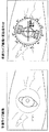
図5は、診断画像の0°線(点線)が重ね合わされた眼の画像を概略的に示す図である。さらに図示するのは、実際のライブ画像(実線のX軸)の0°線およびトーリックレンズの向き(orientation)(破線)である。基準座標系との比較(リアルタイム画像のX軸と診断画像で0°線である点線との比較)から、外科医は、診断画像と比較してリアルタイム画像がどれほど傾斜しているかを同定することができる。破線から、外科医は、トーリックレンズを合わせる必要がある方向を同定することができる。なぜなら、前の実施形態と同様に、基準画像とリアルタイム画像の間の位置合わせおよび/または追跡から得られる座標変換の適用により、破線は、基準画像と比較してリアルタイム画像の動作を補正する位置に表示されるからである。 FIG. 5 is a diagram schematically showing an eye image in which the 0 ° line (dotted line) of the diagnostic image is superimposed. Further illustrated are the 0 ° line of the actual live image (solid X axis) and the toric lens orientation (dashed line). From the comparison with the reference coordinate system (comparison between the X-axis of the real-time image and the dotted line that is the 0 ° line in the diagnostic image), the surgeon can identify how much the real-time image is tilted compared to the diagnostic image. it can. From the dashed line, the surgeon can identify the direction in which the toric lens needs to be aligned. Because, as in the previous embodiment, by applying coordinate transformation obtained from registration and / or tracking between the reference image and the real-time image, the broken line is a position that corrects the operation of the real-time image compared to the reference image. It is because it is displayed.
この実施形態で2本の線(診断0°線とリアルタイム画像の0°線)が互いに合致しない理由は、手術中、基準画像からリアルタイム画像へ眼が幾分動くためである。これは、基準画像の0°線(点線として示す)とリアルタイム画像のX軸(実線で、そしてリアルタイム画像の座標系のX軸として示す)との間の勾配によって示される。リアルタイム画像で、眼が全く動かず厳密に同じ位置にあり、基準画像を撮影したときと全く同じであった場合、点線(基準画像の0°線)とリアルタイム画像のX軸は一致するはずである。しかし、眼の動きにより、(眼の1個以上の特徴または目印に基づき)基準画像中で最初に定義した座標系は、ここで移行しおそらくさらに回転し、従って図5から分かるように、通常、診断0°線とリアルタイム画像の0°線はもはや一致しない。
The reason that the two lines (diagnostic 0 ° line and real-
図5では、例えば、角膜縁および他の眼の特徴を利用することによって、基準画像で、そしてさらにリアルタイム画像で自動的に決められる0°線を示す。角膜縁は、例えば、円に合わせることが可能であり、次いでその中心を座標系の原点として使用しうる。他の任意の特徴(例えば、血管)をX軸およびY軸の方向を決定するための基準として使用してよく、その際、座標系決定アルゴリズムが、座標系の位置を、基準画像およびリアルタイム画像の座標系が眼の中の同じ位置にあるように明確に決定する限り、これらの軸の実際の方向はそれほど重要ではない。一度、座標系を決定すれば、座標系のX軸は(点線として図5に示すように)0°軸として強調してよく、さらにトーリックIOLを整合しなければならない(図5で破線として示す)整合軸を重ね合わせて表示することができる。この後者の軸は手術計画段階中に外科医が基準画像にコンテクストデータを加えたとき、グラフィックユーザーインターフェースを使用し(例えば、マウスにより)、外科医によって決定される。(0°線と整合軸が定義された)基準画像とリアルタイム画像の間の位置合わせおよび/または追跡から得られる座標変換に基づき、リアルタイム画像に0°線(点線)および整合軸(破線)が示される。リアルタイム画像で基準画像の座標系を再度位置づけることにより、2つの座標系を一致させる座標変換を得ることができ、そしてコンテクストデータ(0°線(点線)および整合軸(破線))にこの座標変換を適用し、その結果、それらは、リアルタイム画像中で、それらが基準画像の中で定義されたのと同じ位置に表示される。従って外科医は図5に示す整合軸をトーリックレンズを整合するために使用することができる。
以下に記載する別の実施形態によれば、外科医の有水晶体IOLの側方位および角度設置を支援する装置が提供される。
FIG. 5 shows a 0 ° line that is determined automatically in the reference image and further in the real-time image, for example by utilizing the corneal border and other eye features. The corneal edge can, for example, fit a circle and then its center can be used as the origin of the coordinate system. Any other feature (eg, blood vessel) may be used as a reference for determining the X-axis and Y-axis directions, in which the coordinate system determination algorithm determines the position of the coordinate system, the reference image and the real-time image. The actual orientation of these axes is not very important, as long as it is clearly determined that their coordinate system is at the same position in the eye. Once the coordinate system is determined, the X axis of the coordinate system may be highlighted as the 0 ° axis (as shown in FIG. 5 as a dotted line) and the toric IOL must be aligned (shown as a dashed line in FIG. 5). ) The alignment axis can be displayed superimposed. This latter axis is determined by the surgeon using a graphical user interface (eg, with a mouse) when the surgeon adds contextual data to the reference image during the surgical planning phase. Based on the coordinate transformation obtained from registration and / or tracking between the reference image and the real-time image (0 ° line and alignment axis defined), the real-time image has a 0 ° line (dotted line) and an alignment axis (dashed line). Indicated. By re-positioning the coordinate system of the reference image in the real-time image, a coordinate transformation that matches the two coordinate systems can be obtained, and this coordinate transformation into the context data (0 ° line (dotted line) and alignment axis (dashed line)) So that they are displayed in the real-time image at the same position as they were defined in the reference image. Thus, the surgeon can use the alignment axis shown in FIG. 5 to align the toric lens.
In accordance with another embodiment described below, an apparatus is provided for assisting a surgeon in lateral orientation and angular placement of a phakic IOL.
有水晶体IOLは、患者の眼の虹彩の前に設置され、専用の固定成分または触覚(haptics)によって虹彩に固定する。既存のヒトの眼の水晶体は眼に残存させて、新たに挿入した有水晶体IOLと一緒に機能させ遠近調節させる。多焦点、トーリック、または多焦点−トーリック有水晶体IOLが利用できるので、この有水晶体IOLの側方位およびトーリック設置は特に重要である。 The phakic IOL is placed in front of the iris of the patient's eye and is fixed to the iris by dedicated fixation components or haptics. The lens of the existing human eye is left in the eye and functions together with the newly inserted phakic IOL to adjust the perspective. Since multifocal, toric, or multifocal-toric phakic IOLs are available, the lateral orientation of the phakic IOL and toric placement are particularly important.
理論上では、視線と同様に、明所視瞳孔(小)および暗所視瞳孔(大)の位置は、手術時に有水晶体IOLの中心を位置決めするのに役立つであろう。このようにして、有水晶体IOL−特に多焦点有水晶体IOL-を使用する眼光学の正確な補正が実現されよう。しかし、実際には、今までのところ、有水晶体IOLはこの情報なしに位置決めされている。通常、レンズに伴う視覚的または精神的欠陥は手術後に同定され、再手術を行って修正される。 Theoretically, as with line of sight, the location of the photopic pupil (small) and scotopic pupil (large) will help to position the center of the phakic IOL during surgery. In this way, an accurate correction of the eye optics using the phakic IOL—especially the multifocal phakic IOL— will be realized. In practice, however, the phakic IOL has so far been positioned without this information. Usually, visual or mental defects associated with the lens are identified after surgery and corrected by re-operation.
しかし、有水晶体IOL手術用の位置合わせおよび追跡を利用することによって、有水晶体IOLの位置変化(translation)および回転、そして角膜縁位置、明所視瞳孔、暗所視瞳孔、および視線を考慮しながら患者の眼に対して有水晶体IOLの正確な位置を同定するために、中間的手術計画ステップが利用できる。有水晶体IOLの最終位置を知り、触覚用のアンカー領域も同様に計画することができる。 However, by taking advantage of alignment and tracking for phakic IOL surgery, it takes into account the translation and rotation of the phakic IOL and the corneal marginal position, photopic pupil, scotopic pupil, and line of sight However, an intermediate surgical planning step can be used to identify the exact location of the phakic IOL relative to the patient's eye. Knowing the final position of the phakic IOL, the tactile anchor area can be planned as well.
上記の情報の全てを、視覚的コンテクスト情報として、診断画像にタグを付け標識することができる。明所視瞳孔および暗所視瞳孔は、例えば診断画像で測定してよい。IOL手術用の位置合わせを利用し、手術時の眼の座標系と診断画像の眼の座標系の位置合わせを行い、次いで、位置合わせによって決定した座標変換を使用し、リアルタイム画像に、明所視瞳孔および暗所視瞳孔などのコンテクスト情報を重ね合わせることができる。IOL手術用の追跡を利用し、手術中の眼の座標系は、診断用の眼の座標系と一貫して合致する。この方式で、医師は、現在の手術用顕微鏡画像上に、手術計画ステップで加えた視覚的コンテクスト情報を重ね合わせることができる。 All of the above information can be tagged and labeled as a diagnostic image as visual context information. The photopic pupil and the scotopic pupil may be measured with a diagnostic image, for example. Using the alignment for the IOL surgery, align the eye coordinate system at the time of surgery and the eye coordinate system of the diagnostic image, then use the coordinate transformation determined by the alignment, Context information such as the visual pupil and the dark-sighted pupil can be superimposed. Utilizing tracking for IOL surgery, the eye coordinate system during surgery is consistently consistent with the diagnostic eye coordinate system. In this manner, the doctor can superimpose the visual context information added in the surgical planning step on the current surgical microscope image.
図6は、コンテクスト情報として、例えば、診断/計画段階中に明所視瞳孔および暗所視瞳孔の平均として決定された瞳孔をリアルタイム画像で重ね合わせ(オーバーレイ)として示す図である。この情報は、有水晶体IOL手術中、外科医を支援する。医師個々の診断に応じて、標準的瞳孔は例えば明所視瞳孔および暗所視瞳孔から得ることができ、また手術計画ステップにおいて診断画像に結びつけることができ、そしてリアルタイム画像に重ね合わせることができる。これは、点線円として図6に示され、基準画像を用いて定義したIOLを固定するアンカー領域に加えて、図6に示すように、リアルタイム画像に示される。 FIG. 6 is a diagram illustrating, as context information, for example, a pupil determined as an average of the photopic pupil and the scotopic pupil during the diagnosis / planning stage as an overlay on the real-time image. This information assists the surgeon during phakic IOL surgery. Depending on the physician's individual diagnosis, the standard pupil can be obtained from, for example, the photopic pupil and the scotopic pupil, and can be tied to the diagnostic image in the surgical planning step and can be superimposed on the real-time image . This is shown in FIG. 6 as a dotted circle and is shown in the real-time image as shown in FIG. 6 in addition to the anchor region that fixes the IOL defined using the reference image.
図7は、コンテクスト情報として視線(これもまた計画または診断段階中に決定されたであろう)をリアルタイム画像に重ね合わせた図である。 FIG. 7 is a diagram in which a gaze (which would also have been determined during the planning or diagnosis phase) as context information is superimposed on the real-time image.
同じ計画、位置合わせおよび追跡技法は、移植の位置決めおよび回転が臨床結果に重要な意味をもつ関連する手術領域に適用することができる。例は、角膜はめこみ(インレー)または角膜上張り(アンレー)であろう。 The same planning, alignment and tracking techniques can be applied to relevant surgical areas where implant positioning and rotation has important implications for clinical outcome. An example would be corneal inlay (inlay) or corneal overlay (onlay).
以下に記載する別の実施形態によれば、角膜トポメトリデータまたは波面データなどの診断データを重ね合わせることによって、外科医を支援する装置が提供される。 According to another embodiment described below, an apparatus is provided for assisting a surgeon by overlaying diagnostic data such as corneal topometry data or wavefront data.
この実施形態では、診断と手術の間の位置合わせは6D位置合わせに基づき、そして手術中の追跡は6D追跡に基づくと考えられる。そのような6次元の位置合わせおよび追跡を実施できる装置は、例えば、DE 10 2006002 001 A1に開示されている。以下で明らかになるように、そのようなシステムを用いて、手術中よりいっそう洗練されたデータを可視化することができる。 In this embodiment, the alignment between diagnosis and surgery is considered based on 6D alignment, and intraoperative tracking is considered based on 6D tracking. An apparatus capable of performing such 6-dimensional registration and tracking is disclosed, for example, in DE 10 2006002 001 A1. As will become apparent below, such a system can be used to visualize more sophisticated data during surgery.
従来的には、トポメトリデータは、通常、診断器具の単一の画像または単一の全体像から決定される。一つの前提は、患者を診断器具の中心に固定することであるが、実際には必ずしもそうなるわけではない。診断から手術へ6D位置合わせを利用する場合、患者の固定はもはや関係しない。6D位置合わせを利用し全6個の自由度での眼の元の位置を決定でき、手術中、顕微鏡下での眼の6D位置に応じて、オンラインでの再計算による角膜トポメトリとして、角膜のトポメトリデータを可視化することができる。 Traditionally, topometry data is usually determined from a single image or a single overview of a diagnostic instrument. One premise is to fix the patient in the center of the diagnostic instrument, but in practice this is not always the case. When utilizing 6D registration from diagnosis to surgery, patient fixation is no longer relevant. 6D alignment can be used to determine the original position of the eye in all 6 degrees of freedom, depending on the 6D position of the eye under the microscope during surgery, as corneal topometry by online recalculation, Topometry data can be visualized.
この実施形態では、眼の6次元位置を決定し、次いで追加のコンテクスト情報として、角膜のトポメトリデータまたは波面データを取得する。6次元眼画像との6次元的空間関連性において診断ステップ中に取得されたこのデータは、次いで保存することができ、位置合わせ後でかつ追跡の利用によって、手術中眼のリアルタイム画像にそれを重ね合わせることができる。これは、位置合わせおよび追跡から得られた座標変換に基づいて6次元診断情報(波面データまたはトポメトリデータ)の位置を再度計算することによって行う。そして、この診断データ(波面データまたはトポメトリデータ)は、手術中眼のリアルタイム画像にそれを重ね合わせることによって表示できる。 In this embodiment, the 6-dimensional position of the eye is determined and then corneal topometry data or wavefront data is acquired as additional context information. This data acquired during the diagnostic step in the 6-dimensional spatial relationship with the 6-dimensional eye image can then be stored and applied to the real-time image of the intraoperative eye after registration and by use of tracking. Can be overlapped. This is done by recalculating the position of the 6-dimensional diagnostic information (wavefront data or topometry data) based on the coordinate transformation obtained from alignment and tracking. This diagnostic data (wavefront data or topometry data) can be displayed by superimposing it on a real-time image of the eye during surgery.
これは、外科医とって大変好都合であり、外科医が手術を実施するのを支援するものである。図8には、トポメトリデータまたは波面データなどのデータの重ね合わせを例示する。 This is very convenient for the surgeon and assists the surgeon in performing the operation. FIG. 8 illustrates the superposition of data such as topometry data or wavefront data.
手術中にリアルタイムでの波面測定の実施を試みる他の手法(例えば、US 2005 /0241653 A1に記載した手法)と比較して、この手法には顕著な利点がある。この方法の1つの主要な利点は、手術中に物理的に操作した眼に基づいて角膜を測定せずに、診断中にリラックスした眼に基づいて測定することである。この方式では、手術中に可視化した情報は、眼の手術条件に依存せず、重ね合わせた情報は、手術中眼の物理的操作によって生じた歪みの影響を受けない「本物の」診断情報である。 This approach has significant advantages compared to other approaches that attempt to perform real-time wavefront measurements during surgery (eg, the approach described in US 2005/0241653 A1). One major advantage of this method is that it does not measure the cornea based on an eye that is physically manipulated during surgery, but instead measures it based on a relaxed eye during diagnosis. In this method, the information visualized during surgery does not depend on the surgical conditions of the eye, and the superimposed information is “real” diagnostic information that is not affected by the distortion caused by the physical operation of the eye during surgery. is there.
以下、図9に関連して、さらなる実施形態および、どのように3つの工程段階、すなわち診断、手術計画および手術が段階的に行われるかを記載することになる。 In the following, with reference to FIG. 9, a further embodiment and how three process steps are performed, ie diagnosis, surgical planning and surgery are performed in stages.
診断的側面では、医師は、診断器具(例えば、トポメーター(topometer)またはIOL-master)を使用して、後のIOL手術に必要なパラメーターを決定する。その器具は、IOL手術用の位置合わせおよび追跡を可能にする十分なピクセル分解能と可視照度(visible illumination:例えば、白色または緑色)を備えた眼の画像を取得できなくてはならない。この「診断画像」は、診断データと以下の工程ステップ全てのための、原座標系を定義する基準画像として使用される。図9の上部分は、そのような診断画像または基準画像を概略的に図示する。先に説明したように、診断ステップはさらにトポメトリデータまたは波面データの取得を含み得る。 In the diagnostic aspect, the physician uses a diagnostic instrument (eg, a topometer or IOL-master) to determine the parameters required for subsequent IOL surgery. The instrument must be able to acquire an eye image with sufficient pixel resolution and visible illumination (eg, white or green) to allow alignment and tracking for IOL surgery. This “diagnostic image” is used as a reference image defining the original coordinate system for the diagnostic data and all the following process steps. The upper part of FIG. 9 schematically illustrates such a diagnostic or reference image. As explained above, the diagnostic step may further include obtaining topometry data or wavefront data.
手術計画ステップは、手術における将来の行為を医師が計画できるようにする、診断と手術の間の中間ステップである。診断画像では、角膜縁、および角膜縁外側の眼の特徴を測定して原座標系を定義する。手術プランナーソフトウェアを使用し、診断画像上に視覚的要素を付加し、重ね合わせし、操作し、充実させることによって、異なる種類のコンテクスト情報(例えば、切開、円柱軸、視線など)を、この原座標系に関連付けることができ、一実施形態では、このソフトウェアは、ユーザーに診断画像の位置または領域を定義させるグラフィックユーザーインターフェースである。そのソフトウェアは、既存の文献データを使用して手術計画用の関連位置を算出できるいくつかのアルゴリズムを実行することによって、医師が正しい切開、円柱軸または他の関連のパラメーターを見出す際に、医師を支援する支援機能を含み得る。 The surgery planning step is an intermediate step between diagnosis and surgery that allows the physician to plan future actions in the surgery. In the diagnostic image, the original coordinate system is defined by measuring the features of the eye on the corneal margin and outside the corneal margin. By using surgical planner software to add, overlay, manipulate, and enrich visual elements on diagnostic images, different types of context information (eg, incisions, cylindrical axes, line of sight, etc.) In one embodiment, the software is a graphical user interface that allows a user to define the location or area of a diagnostic image. The software performs several algorithms that can use existing literature data to calculate the relevant location for the surgical plan, so that the physician can find the correct incision, cylinder axis or other relevant parameters. A support function for supporting
図9に示す実施形態では、左下部分に、標準的瞳孔(点線円)の挿入(または定義)および円柱軸(破線で示し、例えば、トーリックレンズを合わせるためもの)の定義を備えた計画を例示する。 The embodiment shown in FIG. 9 illustrates a plan with a standard pupil (dotted circle) insertion (or definition) and a cylindrical axis definition (shown in broken lines, eg, for fitting a toric lens) in the lower left part. To do.
医師は、患者の存在とは無関係に、かつ例えば褪せてゆくインクマーカーによる時間的制約なしに、計画ステップを実行できる。さらにまた後で手術中に使用されるように、後の診療で再計算し再利用できる固定された座標系により、複数の患者診療を順次計画することができる。 The physician can execute the planning steps regardless of the patient's presence and without time constraints due to, for example, the fading ink markers. Furthermore, multiple patient visits can be planned sequentially with a fixed coordinate system that can be recalculated and reused in later visits for later use during surgery.
患者の手術プランナーソフトウェアの出力データ(計画内容)は、ネットワークまたはメモリスティック器具を使用し手術環境へ転送しうる。別の実施形態によれば、計画ステップは手術の位置合わせおよび追跡と同じコンピューターで実施される。その場合そのような転送はもはや必要ではない。 The patient's surgical planner software output data (plan content) may be transferred to the surgical environment using a network or memory stick instrument. According to another embodiment, the planning step is performed on the same computer as the surgical registration and tracking. In that case such a transfer is no longer necessary.
手術環境では、位置合わせおよび追跡処理ユニットは、顕微鏡カメラからオンラインの眼画像(手術画像)を取得処理する。次いで、外科医の椅子付近の(タッチスクリーン)モニター、または顕微鏡のモニターが、手術画像をオンライン(リアルタイム)で表示する。一実施形態では、追跡と重ね合わせを実行する処理ユニットとの相互作用は、タッチスクリーンモニターまたは、例えば重ね合わせ情報をオンまたはオフに切り替えるための足ペダルにより可能になる。現在の患者の計画内容(コンテクスト情報)を顕微鏡カメラに連結した処理ユニットにロードし、位置合わせおよび追跡を通じて、それを手術中のリアルタイム画像に重ね合わせることができる。 In the surgical environment, the registration and tracking processing unit acquires and processes online eye images (surgical images) from the microscope camera. A monitor near the surgeon's chair (touch screen) or a microscope monitor then displays the surgical image online (in real time). In one embodiment, interaction with the processing unit performing tracking and overlaying is enabled by a touch screen monitor or a foot pedal, for example to switch overlay information on or off. The current patient plan content (context information) can be loaded into a processing unit connected to a microscope camera and superimposed on a real-time image during surgery through registration and tracking.
患者の眼の準備後、手術の初めに、医師は、診断画像と手術画像の位置合わせを作動させ、診断から手術への絶対的座標変換(診断変換)を確定する。診断画像との位置合わせが成功した選択手術画像は、手術基準画像として保存される。 After preparing the patient's eye, at the beginning of the surgery, the physician activates the alignment of the diagnostic and surgical images to determine the absolute coordinate transformation (diagnostic transformation) from diagnosis to surgery. The selected surgical image that has been successfully aligned with the diagnostic image is stored as a surgical reference image.
手術中、医師は、計画内容(コンテクスト情報)を可視化したいとき、いつでも重ね合わせ機能を作動させることができる。これは、手術状態下で眼を追跡することによって実現し、その際、各追跡期間Pについて、(診断画像から手術基準画像への変換である)診断変換とPの現在の手術画像から第1の手術画像への座標変換が加算される。このようにして、コンテクスト情報が、眼の動きにもかかわらず、常に、その眼のリアルタイム画像の同じ位置に表示される。 During surgery, the doctor can activate the overlay function whenever he wants to visualize the plan content (context information). This is accomplished by tracking the eye under surgical conditions, where for each tracking period P, the first from the diagnostic transformation (which is a transformation from a diagnostic image to a surgical reference image) and P's current surgical image. The coordinate transformation to the surgical image is added. In this way, the context information is always displayed at the same position in the real-time image of the eye regardless of the movement of the eye.
図9の例では、下右手側に重ね合わせを示す。0°線とリアルタイム画像の0°線のずれから、この例では、眼は診断または基準段階での眼の向きと完全には合致していないことが分かる。診断画像とリアルタイム画像の間には、角度指標が画像自体のX軸と比較して傾斜していることによって示されるように、0°線によって可視化される幾分かの回転変位がある。 In the example of FIG. 9, superposition is shown on the lower right hand side. From the deviation of the 0 ° line and the 0 ° line of the real-time image, it can be seen that in this example the eye does not perfectly match the eye orientation at the diagnosis or reference stage. There is some rotational displacement between the diagnostic image and the real-time image that is visualized by the 0 ° line, as shown by the angle index being tilted relative to the X axis of the image itself.
図10は、実際の手術計画ステップを幾分か、より詳細に示す。まず(図10の左手側)、基準画像の座標系を、例えば、原点が角膜縁の中心と合致し、X軸が画像自体のX方向と平行になるように決定する。次いで、角度指標が算出されるが、その際、角膜縁に適合する円は、0°〜180°の角度で示される上半分と0°〜180°の角度で示される下半分に分割される。次いで、図10の右手側に示されるように、この診断基準画像に基づき、ここでは例として軸(破線)と標準的瞳孔(点線円)であるコンテクストデータを加える。切開マークなどの他のコンテクスト情報を同様に加えることもできよう。 FIG. 10 shows the actual surgical planning steps in some more detail. First (left hand side in FIG. 10), the coordinate system of the reference image is determined so that, for example, the origin coincides with the center of the cornea edge and the X axis is parallel to the X direction of the image itself. An angle index is then calculated, where the circle that fits the limbus is divided into an upper half indicated by an angle between 0 ° and 180 ° and a lower half indicated by an angle between 0 ° and 180 °. . Next, as shown on the right hand side of FIG. 10, based on this diagnostic reference image, here, context data that is an axis (broken line) and a standard pupil (dotted circle) is added as an example. Other context information such as incision marks could be added as well.
切開マーカーまたは整合軸のようなコンテクスト情報については、全ての操作を2次元画像のみを使用して実施することができる。しかし、トポメトリデータまたは波面データなどの情報をコンテクスト情報として使用する場合、先に説明したように、6次元の位置合わせおよび追跡工程を使用するのが好ましい。 For context information such as incision markers or alignment axes, all operations can be performed using only two-dimensional images. However, when information such as topometry data or wavefront data is used as context information, it is preferable to use a 6-dimensional alignment and tracking process as described above.
先に記載した実施形態は、従来技術に対する顕著な利点をもたらすが、それらのいくつかを以下に列挙する。要約すると、本発明には以下の顕著な利点がある。
− IOL手術方法のスピードアップおよび単純化:IOL工程で、特にトーリックIOLで、時間がかかるインクマーカーおよびスタンプツールをもはや必要としない。
− 工程精度:誤差が生じやすいマーカーおよびプリントアウト技法が回避される。
− 工程の安全性:診断と手術の間を自動的に結合するために異常値が少ない。
− 手術計画および手術に、リラックスした眼の診断データが使用される(手術中に得られた歪められた眼のデータではない)。
The previously described embodiments provide significant advantages over the prior art, some of which are listed below. In summary, the present invention has the following significant advantages.
-Speed up and simplification of IOL surgical methods: Time consuming ink markers and stamp tools are no longer needed in the IOL process, especially in toric IOLs.
-Process accuracy: avoid error-prone markers and printout techniques.
-Process safety: there are few outliers to automatically link between diagnosis and surgery.
-Relaxed eye diagnostic data is used for surgery planning and surgery (not distorted eye data obtained during surgery).
デジタル画像を撮影するカメラ、および診断画像または基準画像の取得、コンテクスト情報の付加、位置合わせおよび追跡に基づきリアルタイム画像に重ね合わせたコンテクスト情報の使用を可能にする処理ユニットを加えることによって、装置全体は、既存の手術顕微鏡に比較的容易に組み込むことができる。 The entire device by adding a camera that captures digital images and a processing unit that allows the use of contextual information superimposed on real-time images based on acquisition of diagnostic or reference images, addition of contextual information, registration and tracking Can be incorporated into existing surgical microscopes relatively easily.
先に記載した実施形態は、ハードウェアによって、ソフトウェアによって、またはソフトウェアとハードウェアを組み合せることによって実施し得ることは当業者によって理解されよう。本発明の実施形態と関連して記載したモジュールおよび機能は、本発明の実施形態に関連して説明した方法に従って行動するなど、適切にプログラムされているマイクロプロセッサまたはコンピューターにより、全体としてまたは部分的に実施し得る。 It will be appreciated by those skilled in the art that the embodiments described above may be implemented by hardware, by software, or by a combination of software and hardware. The modules and functions described in connection with embodiments of the present invention may be wholly or partly by a suitably programmed microprocessor or computer, such as acting according to the methods described in connection with embodiments of the present invention. Can be implemented.
本発明の実施形態によれば、データ担体に保存されるか、または他の方式で記録媒体または伝達リンクなど、いくつかの物理的手段によって具体化されるコンピュータープログラムが提供され、このプログラムは、コンピューターで実行したとき、コンピューターが、先に記載した本発明の実施形態に従って作動できるようにするものである。 According to an embodiment of the present invention there is provided a computer program stored on a data carrier or otherwise embodied by some physical means, such as a recording medium or a transmission link, When executed on a computer, the computer is operable in accordance with the embodiments of the invention described above.
Claims (15)
前記装置で眼の基準画像を取得するステップ、
眼の手術を実施する際に外科医にとって役立つ追加のコンテクスト情報であって、外科医が外科手術を実施すべき位置又は領域と、眼内レンズを設置する位置又は向きの少なくとも一つを図示するコンテクスト情報を前記装置内で挿入することによって、該基準画像を充実(enrich)させるステップ、
前記装置で眼のリアルタイム画像と該基準画像の位置合わせをするステップ、および
眼の動きにかかわらず該コンテクスト情報が同じ位置に表示されるように、前記装置で眼の動きの追跡に基づいて眼のリアルタイム画像に該コンテクスト情報を重ね合わせるステップ
を含む方法。 An image processing method executed by an image processing apparatus for computer-assisted intraocular lens surgery,
Obtaining a reference image of the eye with the device ;
Additional context information useful to the surgeon when performing eye surgery, the context information illustrating at least one of the location or area where the surgeon should perform the surgery and the location or orientation where the intraocular lens is to be placed Enriching the reference image by inserting in the device ;
Aligning the real-time image of the eye with the reference image at the device and displaying the context information at the same position regardless of eye movement based on tracking of the eye movement at the device. Superimposing the context information on a real-time image of the method.
前記基準画像の眼の1個以上の特徴に基づく座標系決定アルゴリズムを使用し第1座標系を決定するステップ、
該座標系に基づき前記コンテクスト情報の空間位置を決定するステップ、
該座標系決定アルゴリズムを使用し手術中に撮影したリアルタイム画像での第2座標系を決定するステップ、
該第1座標系から該第2座標系への座標変換を確定することによって、該コンテクスト情報を重ね合わせる位置を決定するステップ
を含む、請求項1に記載の方法。 further,
Determining a first coordinate system using a coordinate system determination algorithm based on one or more features of the eye of the reference image;
Determining a spatial position of the context information based on the coordinate system;
Determining a second coordinate system in a real-time image taken during surgery using the coordinate system determination algorithm;
The method according to claim 1, further comprising: determining a position to superimpose the context information by determining a coordinate transformation from the first coordinate system to the second coordinate system.
さらなるリアルタイム画像とリアルタイム画像配列の初期画像との比較に基づいて眼の動きを追跡し第2座標変換を取得し、そして該第1座標変換と該第2座標変換の組合せに基づき、該基準画像から該リアルタイム画像配列のリアルタイム画像への最終座標変換を取得し、該組み合わされた座標変換に基づき該リアルタイム画像に該コンテクスト情報を表示できるようにするステップ、または
リアルタイム画像配列のリアルタイム画像と該基準画像の位置合わせを行い該基準画像から該リアルタイム画像配列のリアルタイム画像への座標変換を取得し、得られた該座標変換に基づいて該リアルタイム画像に該コンテクスト情報を表示できるようにするステップ
を含む、請求項1または2に記載の方法。 Aligning the initial image of the real-time image array with the reference image to obtain an initial coordinate transformation;
Tracking the eye movement and obtaining a second coordinate transformation based on the comparison of the further real-time image and the initial image of the real-time image array, and based on the combination of the first coordinate transformation and the second coordinate transformation, the reference image Obtaining a final coordinate transformation from the real-time image sequence to a real-time image and allowing the context information to be displayed on the real-time image based on the combined coordinate transformation, or a real-time image of the real-time image sequence and the reference Aligning images, obtaining a coordinate transformation from the reference image to a real-time image of the real-time image array, and allowing the context information to be displayed on the real-time image based on the obtained coordinate transformation. The method according to claim 1 or 2.
診断目的に有用である眼の特性またはパラメーターである、眼のトポメトリデータまたは波面データを図示する診断データを含む、請求項1〜3の一項に記載の方法。 The context information is
4. The method according to one of claims 1 to 3, comprising diagnostic data illustrating ocular topometry data or wavefront data that are ocular characteristics or parameters useful for diagnostic purposes.
切開を行った位置をマーキングするための1個以上の切開マーク、
トーリック眼内レンズを置くための円柱軸、
器具を固定するための1個以上のアンカー領域、
正しい位置に有水晶体眼内レンズを置くための、瞳孔マークまたは視線マーク、
角膜インレーまたは角膜アンレーの位置
の1個以上を含む、請求項1〜6の一項に記載の方法。 The context information is
One or more incision marks for marking the location of the incision;
Cylindrical axis for placing toric intraocular lens,
One or more anchor regions for securing the instrument;
Pupil mark or line-of-sight mark to place the phakic intraocular lens in the correct position ,
Comprising one or more positions of corneal inlays or corneal onlays Method according to one of claims 1 to 6.
眼の基準画像を取得するモジュール、
眼の手術を実施する際に外科医にとって役立つ追加のコンテクスト情報であって、外科医が外科手術を実施すべき位置又は領域と、眼内レンズを設置する位置又は向きの少なくとも一つを図示するコンテクスト情報を挿入することによって、該基準画像を充実させるモジュール、
眼のリアルタイム画像と該基準画像の位置合わせを行うモジュール、および
眼の動きにかかわらず該コンテクスト情報が同じ位置に表示されるように、眼の動きの追跡に基づいて眼のリアルタイム画像に該コンテクスト情報を重ね合わせるモジュール
を含む装置。 An image processing device for computer-assisted intraocular lens surgery,
A module for acquiring a reference image of the eye,
Additional context information useful to the surgeon when performing eye surgery, the context information illustrating at least one of the location or area where the surgeon should perform the surgery and the location or orientation where the intraocular lens is to be placed A module that enhances the reference image by inserting
A module for aligning the real-time image of the eye and the reference image, and the context information in the real-time image of the eye based on tracking of eye movement so that the context information is displayed at the same position regardless of eye movement. A device that includes a module that superimposes information.
該座標系に基づき前記コンテクスト情報の空間位置を決定するモジュール、
該座標系決定アルゴリズムを使用し手術中に撮影したリアルタイム画像での第2座標系を決定するモジュール、
該第1座標系から該第2座標系への座標変換を決定することによって、該コンテクスト情報を重ね合わせる位置を決定するモジュール
をさらに含む、請求項8に記載の装置。 A module for determining a first coordinate system using a coordinate system determination algorithm based on one or more features of the eye of the reference image;
A module for determining a spatial position of the context information based on the coordinate system;
A module for determining a second coordinate system in a real-time image taken during surgery using the coordinate system determination algorithm;
The apparatus according to claim 8, further comprising a module that determines a position where the context information is superimposed by determining a coordinate transformation from the first coordinate system to the second coordinate system.
さらなるリアルタイム画像とリアルタイム画像配列の初期画像との比較に基づいて眼の動きを追跡し第2座標変換を行い、かつ該第1座標変換と該第2座標変換の組合せに基づき、該基準画像から該リアルタイム画像配列のリアルタイム画像への最終座標変換を取得し、該組み合わせられた座標変換に基づき、該リアルタイム画像に該コンテクスト情報を表示できるようにするモジュール、または
リアルタイム画像配列のリアルタイム画像と該基準画像の位置合わせを行い該基準画像から該リアルタイム画像配列のリアルタイム画像への座標変換を取得し、得られた該座標変換に基づいて、該リアルタイム画像に該コンテクスト情報を表示できるようにするモジュール
をさらに含む、請求項8または9に記載の装置。 A module for aligning the initial image of the real-time image array and the reference image to obtain an initial coordinate transformation, and tracking the eye movement based on the comparison between the further real-time image and the initial image of the real-time image array, and the second coordinate transformation And obtaining a final coordinate transformation from the reference image to a real-time image of the real-time image array based on the combination of the first coordinate transformation and the second coordinate transformation, and based on the combined coordinate transformation, A module that enables the context information to be displayed on a real-time image, or aligns the real-time image of the real-time image array with the reference image and obtains a coordinate conversion from the reference image to the real-time image of the real-time image array. The context is added to the real-time image based on the coordinate transformation. Further comprising a module to be able to view the information, according to claim 8 or 9.
診断目的に有用である眼の特性またはパラメーターである、眼のトポメトリデータまたは波面データを図示する診断データを含む、請求項8〜10の一項に記載の装置。 The context information is
11. An apparatus according to one of claims 8 to 10, comprising diagnostic data illustrating ocular topometry data or wavefront data that are ocular characteristics or parameters useful for diagnostic purposes.
切開を行った位置をマーキングするための1個以上の切開マーク、
トーリック眼内レンズを置くための円柱軸、
器具を固定するための1個以上のアンカー領域、
特に正しい位置に有水晶体眼内レンズを置くための、瞳孔マークまたは視線マーク、
角膜インレーまたは角膜アンレーの位置
の1個以上を含む、請求項8〜13の一項に記載の装置。 The context information is
One or more incision marks for marking the location of the incision;
Cylindrical axis for placing toric intraocular lens,
One or more anchor regions for securing the instrument;
In particular for putting phakic intraocular lens in position, the pupil mark or line-of-sight marks,
Comprising one or more positions of corneal inlays or corneal onlays, according to one of claims 8 to 13.
Applications Claiming Priority (3)
| Application Number | Priority Date | Filing Date | Title |
|---|---|---|---|
| EP08167232.1 | 2008-10-22 | ||
| EP08167232A EP2184005B1 (en) | 2008-10-22 | 2008-10-22 | Method and apparatus for image processing for computer-aided eye surgery |
| PCT/EP2009/063753 WO2010046371A1 (en) | 2008-10-22 | 2009-10-20 | Method and apparatus for image processing for computer-aided eye surgery |
Publications (2)
| Publication Number | Publication Date |
|---|---|
| JP2012506272A JP2012506272A (en) | 2012-03-15 |
| JP5579725B2 true JP5579725B2 (en) | 2014-08-27 |
Family
ID=40469903
Family Applications (1)
| Application Number | Title | Priority Date | Filing Date |
|---|---|---|---|
| JP2011532614A Active JP5579725B2 (en) | 2008-10-22 | 2009-10-20 | Image processing method and apparatus for computer-assisted intraocular lens surgery, and program |
Country Status (11)
| Country | Link |
|---|---|
| US (1) | US8903145B2 (en) |
| EP (2) | EP2184005B1 (en) |
| JP (1) | JP5579725B2 (en) |
| CN (1) | CN102264280B (en) |
| AT (1) | ATE509568T1 (en) |
| BR (1) | BRPI0919756A2 (en) |
| DK (1) | DK2373207T3 (en) |
| ES (1) | ES2750334T3 (en) |
| PL (1) | PL2373207T3 (en) |
| PT (1) | PT2373207T (en) |
| WO (1) | WO2010046371A1 (en) |
Families Citing this family (47)
| Publication number | Priority date | Publication date | Assignee | Title |
|---|---|---|---|---|
| US8820929B2 (en) * | 2006-01-20 | 2014-09-02 | Clarity Medical Systems, Inc. | Real-time measurement/display/record/playback of wavefront data for use in vision correction procedures |
| JP5511516B2 (en) * | 2010-05-31 | 2014-06-04 | 株式会社ニデック | Ophthalmic equipment |
| JP5818409B2 (en) * | 2010-06-17 | 2015-11-18 | キヤノン株式会社 | Fundus imaging apparatus and control method thereof |
| US20120022408A1 (en) * | 2010-06-18 | 2012-01-26 | Vantage Surgical Systems, Inc. | Surgical Procedures Using Visual Images Overlaid with Visual Representations of Selected Three-Dimensional Data |
| PT2621329T (en) * | 2010-09-30 | 2017-05-25 | Wavelight Gmbh | Arrangement for supporting surgical treatment of an eye |
| US8740382B1 (en) * | 2010-09-30 | 2014-06-03 | Cognex Corporation | System and method for automatically tracking a contact lens in a wearer's eye |
| US8231221B2 (en) | 2010-09-30 | 2012-07-31 | Wavelight Gmbh | Arrangement and method for carrying out a surgical treatment of an eye |
| ES2959110T3 (en) | 2010-11-26 | 2024-02-20 | Alcon Inc | Device for multilevel eye registration |
| ES2911679T3 (en) * | 2011-10-22 | 2022-05-20 | Alcon Inc | Apparatus for monitoring one or more surgical parameters of the eye |
| EP2583618B1 (en) * | 2011-10-22 | 2017-12-06 | Alcon Pharmaceuticals Ltd. | Apparatus for monitoring one or more parameters of the eye |
| US9105207B2 (en) | 2012-05-02 | 2015-08-11 | Empire Technology Development Llc | Four dimensional image registration using dynamical model for augmented reality in medical applications |
| EP2682079B1 (en) * | 2012-07-06 | 2014-12-31 | Neoptics AG | System for inserting an intracorneal lens |
| WO2014013438A1 (en) * | 2012-07-16 | 2014-01-23 | Lumenis Ltd. | System for laser application |
| US20140039510A1 (en) * | 2012-07-31 | 2014-02-06 | Paul Van Saarloos | Tps tools and methods for the surgical placement of intraocular implants |
| WO2014122834A1 (en) | 2013-02-06 | 2014-08-14 | Hoya株式会社 | Simulation system, simulation device, and product description assistance method |
| DE102013002293A1 (en) | 2013-02-08 | 2014-08-14 | Carl Zeiss Meditec Ag | Eye surgery systems and methods for inserting intro-cular lenses |
| CN103431941B (en) * | 2013-05-27 | 2015-02-04 | 宋艳萍 | Macular sparing control method and control system for ophthalmic laser treatment equipment |
| DE102013210728A1 (en) | 2013-06-10 | 2014-12-11 | Carl Zeiss Meditec Ag | Operating microscopy system and method for its operation |
| US9968295B2 (en) * | 2013-08-07 | 2018-05-15 | Novartis Ag | Surgical guidance and planning software for astigmatism treatment |
| EP3046518A4 (en) * | 2013-09-18 | 2017-07-05 | Richard Awdeh | Surgical navigation system and method |
| US10327953B2 (en) | 2013-10-31 | 2019-06-25 | Optimedica Corporation | Laser eye surgery lens fragmentation |
| US9597009B2 (en) * | 2013-12-19 | 2017-03-21 | Novartis Ag | Marker-based tool tracking |
| JP5570673B2 (en) * | 2014-03-10 | 2014-08-13 | 株式会社ニデック | Ophthalmic equipment |
| US10254528B2 (en) | 2014-03-13 | 2019-04-09 | Nanophthalmos, Llc | Microscope insert |
| WO2015138994A2 (en) * | 2014-03-13 | 2015-09-17 | Richard Awdeh | Methods and systems for registration using a microscope insert |
| DE102014106993A1 (en) | 2014-05-19 | 2015-11-19 | Chronos Vision Gmbh | Method and device for determining the orientation of the eye during eye surgery |
| KR20160071889A (en) * | 2014-12-12 | 2016-06-22 | 삼성전자주식회사 | Apparatus and method for supporting on diagnosis using multi image |
| JP2016112358A (en) | 2014-12-18 | 2016-06-23 | ソニー株式会社 | Information processing equipment, surgery microscope system, and information processing method |
| US20180049840A1 (en) * | 2015-03-13 | 2018-02-22 | Nanophthalmos, LLC, (Circle) | Methods and systems for registration using a microscope insert |
| JP6786903B2 (en) * | 2015-07-31 | 2020-11-18 | 株式会社ニデック | Intraocular lens insertion system, control device for controlling the intraocular lens insertion device |
| US20170083666A1 (en) * | 2015-09-22 | 2017-03-23 | Novartis Ag | Presurgical planning for use during surgical procedure |
| JP6791135B2 (en) * | 2015-10-15 | 2020-11-25 | ソニー株式会社 | Image processing equipment, image processing methods, and operating microscopes |
| US10820794B2 (en) * | 2015-11-06 | 2020-11-03 | Canon Kabushiki Kaisha | Pupil monitoring method for adaptive optics imaging system |
| JP6880606B2 (en) * | 2016-08-30 | 2021-06-02 | 株式会社ニデック | Ophthalmic Surgical Microscope |
| US10973585B2 (en) | 2016-09-21 | 2021-04-13 | Alcon Inc. | Systems and methods for tracking the orientation of surgical tools |
| DE102016011759B4 (en) * | 2016-09-30 | 2022-01-27 | Chronos Vision Gmbh | Apparatus and method for displaying the axis of astigmatism of the eye |
| DE102017209425A1 (en) | 2017-06-02 | 2018-12-06 | Carl Zeiss Meditec Ag | Eye surgery system and method for preparing for surgery in the context of eye surgery |
| DE102017217375A1 (en) | 2017-09-29 | 2019-04-04 | Carl Zeiss Meditec Ag | Device for reflecting parameters and / or image data into the stereoscopic observation beam path of ophthalmological devices |
| US10970813B2 (en) * | 2018-07-02 | 2021-04-06 | Alcon Inc. | Shaking image for registration verification |
| US20210267799A1 (en) * | 2020-02-21 | 2021-09-02 | Daniel R. Neal | System and Methods for Customizing an Intraocular Lens Using a Wavefront Aberrometer |
| JP2022116559A (en) * | 2021-01-29 | 2022-08-10 | ソニーグループ株式会社 | Image processing device, image processing method, and surgical microscope system |
| WO2022163188A1 (en) * | 2021-01-29 | 2022-08-04 | ソニーグループ株式会社 | Image processing device, image processing method, and surgical microscope system |
| WO2022163189A1 (en) * | 2021-01-29 | 2022-08-04 | ソニーグループ株式会社 | Image processing device, image processing method, and surgical microscope system |
| CN112836747A (en) * | 2021-02-02 | 2021-05-25 | 首都师范大学 | Eye movement data outlier processing method and device, computer equipment and storage medium |
| WO2022181194A1 (en) * | 2021-02-26 | 2022-09-01 | ソニーグループ株式会社 | Image processing device, image processing method, and surgical microscope system |
| WO2023047626A1 (en) * | 2021-09-21 | 2023-03-30 | ソニーグループ株式会社 | Image processing device, image processing method, and surgical microscope system |
| CN114642502B (en) * | 2022-02-21 | 2023-07-14 | 北京工业大学 | Auxiliary design method and device for strabismus operation scheme |
Family Cites Families (21)
| Publication number | Priority date | Publication date | Assignee | Title |
|---|---|---|---|---|
| JP2853783B2 (en) | 1990-10-26 | 1999-02-03 | キヤノン株式会社 | Image translucent transparent film and image forming method using the same |
| JPH04256342A (en) | 1991-02-08 | 1992-09-11 | Toshiba Corp | Semiconductor package |
| JP3036182B2 (en) | 1991-10-31 | 2000-04-24 | ソニー株式会社 | Image coding device |
| DE19950791A1 (en) | 1999-10-21 | 2001-05-10 | Technolas Gmbh | Image alignment in ophthalmic refractive surgery systems for refractive treatment of eye involves aligning two images of eye having spatial relationship, for performing refractive treatment |
| CN100362975C (en) * | 1999-10-21 | 2008-01-23 | 泰思诺拉斯眼科系统公司 | Iris recognition and tracking for optical treatment |
| US7044602B2 (en) * | 2002-05-30 | 2006-05-16 | Visx, Incorporated | Methods and systems for tracking a torsional orientation and position of an eye |
| WO2001089373A2 (en) | 2000-05-20 | 2001-11-29 | Sensomotoric Instruments Gmbh | Method and apparatus for measuring ocular alignment |
| US20050117118A1 (en) | 2001-10-05 | 2005-06-02 | David Miller | Digital ophthalmic workstation |
| CA2475896C (en) * | 2002-02-11 | 2011-08-23 | Visx, Inc. | Determining relative positional and rotational offsets |
| JP4493408B2 (en) * | 2003-06-06 | 2010-06-30 | 富士フイルム株式会社 | Image interpretation support method, apparatus and program |
| ES2665536T3 (en) | 2004-04-20 | 2018-04-26 | Alcon Research, Ltd. | Integrated surgical microscope and wavefront sensor |
| DE102004055683B4 (en) | 2004-10-26 | 2006-09-07 | Carl Zeiss Surgical Gmbh | Eye Surgery Microscopy System and Method Therefor |
| US7815631B2 (en) | 2004-11-30 | 2010-10-19 | Alcon Refractivehorizons, Inc. | Eye registration system for refractive surgery and associated methods |
| US7934833B2 (en) * | 2005-12-22 | 2011-05-03 | Alcon Refractivehorizons, Inc. | Image alignment system for use in laser ablation treatment of the cornea |
| DE102006002001B4 (en) | 2006-01-16 | 2009-07-23 | Sensomotoric Instruments Gmbh | Method for determining the spatial relation of an eye of a person with respect to a camera device |
| US20080013809A1 (en) * | 2006-07-14 | 2008-01-17 | Bracco Imaging, Spa | Methods and apparatuses for registration in image guided surgery |
| US7899226B2 (en) * | 2007-04-03 | 2011-03-01 | General Electric Company | System and method of navigating an object in an imaged subject |
| US8363783B2 (en) * | 2007-06-04 | 2013-01-29 | Oraya Therapeutics, Inc. | Method and device for ocular alignment and coupling of ocular structures |
| US20080312675A1 (en) * | 2007-06-18 | 2008-12-18 | Advanced Medical Optics, Inc. | System and method for calculating limbal relaxing incisions |
| CN102625670B (en) * | 2009-06-16 | 2015-07-15 | 核磁共振成像介入技术有限公司 | MRI-guided devices and MRI-guided interventional systems that can track and generate dynamic visualizations of the devices in near real time |
| JP5763681B2 (en) * | 2010-01-22 | 2015-08-12 | オプティメディカ・コーポレイション | Device for automatic placement of capsulotomy by scanning laser |
-
2008
- 2008-10-22 EP EP08167232A patent/EP2184005B1/en active Active
- 2008-10-22 AT AT08167232T patent/ATE509568T1/en not_active IP Right Cessation
-
2009
- 2009-10-20 JP JP2011532614A patent/JP5579725B2/en active Active
- 2009-10-20 EP EP09737424.3A patent/EP2373207B1/en active Active
- 2009-10-20 WO PCT/EP2009/063753 patent/WO2010046371A1/en active Application Filing
- 2009-10-20 PT PT97374243T patent/PT2373207T/en unknown
- 2009-10-20 DK DK09737424.3T patent/DK2373207T3/en active
- 2009-10-20 ES ES09737424T patent/ES2750334T3/en active Active
- 2009-10-20 CN CN200980151988.9A patent/CN102264280B/en active Active
- 2009-10-20 US US13/125,682 patent/US8903145B2/en active Active
- 2009-10-20 PL PL09737424T patent/PL2373207T3/en unknown
- 2009-10-20 BR BRPI0919756A patent/BRPI0919756A2/en active Search and Examination
Also Published As
| Publication number | Publication date |
|---|---|
| CN102264280B (en) | 2016-01-20 |
| EP2184005B1 (en) | 2011-05-18 |
| ATE509568T1 (en) | 2011-06-15 |
| PT2373207T (en) | 2019-10-18 |
| EP2184005A1 (en) | 2010-05-12 |
| US20110230751A1 (en) | 2011-09-22 |
| PL2373207T3 (en) | 2020-01-31 |
| EP2373207B1 (en) | 2019-09-11 |
| ES2750334T3 (en) | 2020-03-25 |
| BRPI0919756A2 (en) | 2015-12-08 |
| DK2373207T3 (en) | 2019-10-21 |
| JP2012506272A (en) | 2012-03-15 |
| CN102264280A (en) | 2011-11-30 |
| EP2373207A1 (en) | 2011-10-12 |
| US8903145B2 (en) | 2014-12-02 |
| WO2010046371A1 (en) | 2010-04-29 |
Similar Documents
| Publication | Publication Date | Title |
|---|---|---|
| JP5579725B2 (en) | Image processing method and apparatus for computer-assisted intraocular lens surgery, and program | |
| US11071451B2 (en) | Intraocular lens alignment | |
| US20230036067A1 (en) | Real-time surgical reference indicium apparatus and methods for astigmatism correction | |
| AU780951B2 (en) | Eye registration and astigmatism alignment control systems and method | |
| JP2012518472A5 (en) | ||
| WO2019148154A1 (en) | Augmented reality guidance for orthopedic and other surgical procedures | |
| US11490986B2 (en) | System and method for improved electronic assisted medical procedures | |
| WO2013163800A2 (en) | Oral surgery auxiliary guidance method | |
| US20210128251A1 (en) | Medical-technical instrumentation and method | |
| DK2621329T3 (en) | DEVICE FOR SUPPORTING A SURGICAL TREATMENT OF AN EYE | |
| CN113349927B (en) | Navigation system for face autologous fat transplantation operation and virtual scale prompting method | |
| US20230118746A1 (en) | Medical apparatus, method for recording a model dataset, data processing program, and program memory medium | |
| CN113490472A (en) | Medical device for ophthalmic surgery | |
| DAVIDSON | INTRAOPERATIVE GUIDANCE |
Legal Events
| Date | Code | Title | Description |
|---|---|---|---|
| A621 | Written request for application examination |
Free format text: JAPANESE INTERMEDIATE CODE: A621 Effective date: 20120829 |
|
| A711 | Notification of change in applicant |
Free format text: JAPANESE INTERMEDIATE CODE: A711 Effective date: 20130809 |
|
| A131 | Notification of reasons for refusal |
Free format text: JAPANESE INTERMEDIATE CODE: A131 Effective date: 20130820 |
|
| A977 | Report on retrieval |
Free format text: JAPANESE INTERMEDIATE CODE: A971007 Effective date: 20130823 |
|
| A521 | Request for written amendment filed |
Free format text: JAPANESE INTERMEDIATE CODE: A821 Effective date: 20130809 |
|
| A601 | Written request for extension of time |
Free format text: JAPANESE INTERMEDIATE CODE: A601 Effective date: 20131111 |
|
| A602 | Written permission of extension of time |
Free format text: JAPANESE INTERMEDIATE CODE: A602 Effective date: 20131118 |
|
| A601 | Written request for extension of time |
Free format text: JAPANESE INTERMEDIATE CODE: A601 Effective date: 20131213 |
|
| A602 | Written permission of extension of time |
Free format text: JAPANESE INTERMEDIATE CODE: A602 Effective date: 20131220 |
|
| A601 | Written request for extension of time |
Free format text: JAPANESE INTERMEDIATE CODE: A601 Effective date: 20140114 |
|
| A602 | Written permission of extension of time |
Free format text: JAPANESE INTERMEDIATE CODE: A602 Effective date: 20140121 |
|
| A521 | Request for written amendment filed |
Free format text: JAPANESE INTERMEDIATE CODE: A523 Effective date: 20140213 |
|
| A131 | Notification of reasons for refusal |
Free format text: JAPANESE INTERMEDIATE CODE: A131 Effective date: 20140304 |
|
| A521 | Request for written amendment filed |
Free format text: JAPANESE INTERMEDIATE CODE: A523 Effective date: 20140526 |
|
| TRDD | Decision of grant or rejection written | ||
| A01 | Written decision to grant a patent or to grant a registration (utility model) |
Free format text: JAPANESE INTERMEDIATE CODE: A01 Effective date: 20140617 |
|
| A61 | First payment of annual fees (during grant procedure) |
Free format text: JAPANESE INTERMEDIATE CODE: A61 Effective date: 20140709 |
|
| R150 | Certificate of patent or registration of utility model |
Ref document number: 5579725 Country of ref document: JP Free format text: JAPANESE INTERMEDIATE CODE: R150 |
|
| R150 | Certificate of patent or registration of utility model |
Ref document number: 5579725 Country of ref document: JP Free format text: JAPANESE INTERMEDIATE CODE: R150 |
|
| R250 | Receipt of annual fees |
Free format text: JAPANESE INTERMEDIATE CODE: R250 |
|
| R250 | Receipt of annual fees |
Free format text: JAPANESE INTERMEDIATE CODE: R250 |
|
| R250 | Receipt of annual fees |
Free format text: JAPANESE INTERMEDIATE CODE: R250 |
|
| S111 | Request for change of ownership or part of ownership |
Free format text: JAPANESE INTERMEDIATE CODE: R313113 |
|
| S531 | Written request for registration of change of domicile |
Free format text: JAPANESE INTERMEDIATE CODE: R313531 |
|
| R350 | Written notification of registration of transfer |
Free format text: JAPANESE INTERMEDIATE CODE: R350 |
|
| R350 | Written notification of registration of transfer |
Free format text: JAPANESE INTERMEDIATE CODE: R350 |
|
| R250 | Receipt of annual fees |
Free format text: JAPANESE INTERMEDIATE CODE: R250 |
|
| R250 | Receipt of annual fees |
Free format text: JAPANESE INTERMEDIATE CODE: R250 |
|
| R250 | Receipt of annual fees |
Free format text: JAPANESE INTERMEDIATE CODE: R250 |
|
| R250 | Receipt of annual fees |
Free format text: JAPANESE INTERMEDIATE CODE: R250 |