JP5579110B2 - Electric pump - Google Patents
Electric pump Download PDFInfo
- Publication number
- JP5579110B2 JP5579110B2 JP2011059430A JP2011059430A JP5579110B2 JP 5579110 B2 JP5579110 B2 JP 5579110B2 JP 2011059430 A JP2011059430 A JP 2011059430A JP 2011059430 A JP2011059430 A JP 2011059430A JP 5579110 B2 JP5579110 B2 JP 5579110B2
- Authority
- JP
- Japan
- Prior art keywords
- pump
- housing
- motor
- electric
- pump housing
- Prior art date
- Legal status (The legal status is an assumption and is not a legal conclusion. Google has not performed a legal analysis and makes no representation as to the accuracy of the status listed.)
- Expired - Fee Related
Links
Images


Landscapes
- Rotary Pumps (AREA)
- Details And Applications Of Rotary Liquid Pumps (AREA)
Description
本発明は、電動ポンプに関する。 The present invention relates to an electric pump.
従来、ポンプロータとアウタロータとを有するトロコイド型のオイルポンプとして特許文献1に記載の技術が開示されている。この公報には、ポンプロータの内部に固定された駆動軸と電動モータとが連結され、電動モータによってポンプを駆動している。
Conventionally, the technique of
しかし、特許文献1に記載の電動ポンプでは、電動ポンプをポンプカバーの部材と一体のブラケットによって自動変速機等に取り付けており、片持ち支持構造となっているため耐久性の悪化や振動等の原因となりやすい。
本発明の目的とするところは、安定して電動ポンプを支持することが可能な電動ポンプの支持構造を提供することにある。
However, in the electric pump described in
An object of the present invention is to provide a support structure for an electric pump that can stably support the electric pump.
上記目的を達成するため、本発明の電動ポンプは、ポンプ要素を収容するポンプハウジングを電動ポンプ収容部の底面に固定し、モータ要素を収容するモータハウジングを電動ポンプ収容部の開口端周縁に固定した。 In order to achieve the above object, the electric pump of the present invention fixes the pump housing that houses the pump element to the bottom surface of the electric pump housing portion, and fixes the motor housing that houses the motor element to the opening edge periphery of the electric pump housing portion. did.
よって、電動ポンプを両持ち支持構造とすることができ、電動ポンプの径方向の耐震性を向上することができる。 Therefore, the electric pump can have a dual-support structure, and the radial vibration resistance of the electric pump can be improved.
以下、本発明の電動ポンプを実施するための形態を、図面に示す実施例に基づいて説明する。
〔実施例1〕
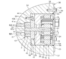
図1は実施例1の電動オイルポンプの縦断面図、図2は図1のS2-S2矢視図、図3は図2からポンプハウジングを取り外した状態を示す図、図4は実施例1の電動オイルポンプの一部分解斜視図である。
実施例1の電動オイルポンプは、アイドルストップ機能を備えた車両の自動変速機用に搭載されるポンプである。この自動変速機はベルト式無段変速機であり、エンジンにより駆動されるメインポンプを別途備えている。そして、アイドルストップ制御によるエンジンの停止時には、メインポンプによる油圧が確保できず、また、ベルト式無段変速機内の摩擦締結要素やプーリからのリーク等によって油圧が低下すると、再発進時に必要な油圧を確保するまでに時間がかかるため、運転性の低下を招く。そこで、メインポンプとは別に、エンジンの作動状態にかかわらず油圧を吐出可能な電動オイルポンプを備え、摩擦締結要素やプーリからのリーク分の油圧を担保することで、エンジン再始動および再発進時の運転性を向上している。
EMBODIMENT OF THE INVENTION Hereinafter, the form for implementing the electric pump of this invention is demonstrated based on the Example shown on drawing.
[Example 1]
1 is a longitudinal sectional view of the electric oil pump according to the first embodiment, FIG. 2 is a view taken along the line S2-S2 in FIG. 1, FIG. 3 is a view showing a state where the pump housing is removed from FIG. It is a partially exploded perspective view of the electric oil pump.
The electric oil pump according to the first embodiment is a pump mounted for an automatic transmission of a vehicle having an idle stop function. This automatic transmission is a belt-type continuously variable transmission, and is separately provided with a main pump driven by an engine. When the engine is stopped by the idle stop control, the hydraulic pressure by the main pump cannot be secured, and if the hydraulic pressure decreases due to a frictional engagement element or a leak from the pulley in the belt type continuously variable transmission, Since it takes time to secure the operability, drivability is reduced. Therefore, in addition to the main pump, an electric oil pump that can discharge hydraulic pressure regardless of the operating state of the engine is equipped, and by ensuring the hydraulic pressure corresponding to the leakage from the frictional engagement elements and pulleys, the engine can be restarted and restarted. Improved drivability.
実施例1の電動オイルポンプは、ポンプ要素1と、モータ要素2と、駆動軸3と、ポンプハウジング4と、モータハウジング5と、電動ポンプ収容部6とを有する。
ポンプ要素1は、6個の外歯歯車(以下、外歯と称す。)を有するポンプロータ7と、7個の内歯歯車(以下、内歯と称す。)を有するアウタロータ8とから構成される。ポンプロータ7は、中心に二面幅を有する連結穴9が形成され、駆動軸3の先端に形成された二面幅10と嵌合する。これにより、駆動軸3とポンプロータ7との回転方向相対位置が決定されると共にトルク伝達が行われる。連結穴9と二面幅10により、駆動軸3とポンプロータ7とをトルク伝達可能、かつ、軸方向への移動を許容して連結する連結部が構成される。
モータ要素2は、駆動軸3と一体に設けられたモータロータ11とステータ12とから構成される。ステータ12のステータコア13に形成された複数のティースにそれぞれコイル14が巻回されてスロットを形成している。モータロータ11は、断面略コの字状の円筒部材であり、円筒外周に永久磁石がN極とS極とが交互に並ぶように複数個取り付けられている。
The electric oil pump according to the first embodiment includes a
The
The
ポンプハウジング4は、円筒部材15と平板部材16とを有し、内部にアウタロータ8が回転可能に収装されている。ポンプハウジング4の外径は、電動ポンプ収容部6の内径よりも小さく形成されている。
円筒部材15は、軸方向一方側(電動ポンプ収容部6の底面6a側)が開口する有底の円筒状に形成され、その開口端には、径方向外側に延びるフランジ部17が設けられている。フランジ部17には、周方向に等ピッチで3つのボルト穴18が形成されている。円筒部材15の中央には、駆動軸3が貫通する貫通穴15aが形成されている。
平板部材16は、円筒部材15のフランジ部17と同一の外径を有し、吸入口19と吐出口20とが形成されている。吐出口20は、円筒部21により延在されている。吸入口19は、ポンプ要素1の吸入側容積室と対応する位置に配置され、吐出口20は、ポンプ要素1の吐出側容積室と対応する位置に配置されている。平板部材16には、円筒部材15の各ボルト穴18と対応する位置にはボルト穴22が形成されている。
The pump housing 4 includes a
The
The
モータハウジング5は、円筒部材23と平板部材24とを有し、内部にモータ要素2が収容されている。
円筒部材23は、軸方向一方側(電動ポンプ収容部6の開口端6b側)が開口する有底の円筒状に形成され、その開口端には、径方向外側に延びるフランジ部25が設けられている。フランジ部25には、周方向に等ピッチで3つのボルト穴26が形成されている。フランジ部25を除く円筒部材23の外径は、ポンプハウジング4の外径よりも大きく、電動ポンプ収容部6の内径よりも僅かに小さく形成されている。また、フランジ部25の外径は、電動ポンプ収容部6の内径よりも大きく形成されている。
円筒部材23の内周には、ステータ12が固定支持されている。円筒部材23の中央には、駆動軸3が貫通する支持穴27が形成されている。この支持穴27により、駆動軸3が回転可能に支持される。支持穴27の左右には、ポンプハウジング4の内部または外周からモータハウジング5内部へのオイルの侵入を規制するシール部材28,29が設けられている。
平板部材24は、円筒部材23の開口端23aの位置で内部を塞いでいる。
The motor housing 5 includes a
The
A
The
電動ポンプ収容部6は、自動変速機のケース部材30に形成され、底面6a、開口端6b、側面6cを有する円筒状の凹部であって、底面6a側にポンプハウジング4が収容され、開口端6b側にモータハウジング5が収容されている。
底面6aには、吸入油路31と吐出油路32とが開口している。吸入油路31は、吸入口19と対応する位置に設けられ、図外のオイルパン内に開口するオイル吸い込み口と連通する。吐出油路32は、吐出口20と対応する位置に設けられ、図外のコントロールバルブユニットと連通する。吐出油路32の開口端には、拡径部32aが形成され、この拡径部32aには平板部材16の円筒部21が嵌合されている。
また、底面6aには、ポンプハウジング4の円筒部材15および平板部材16の各ボルト穴18,22と対応する位置にネジ穴33が形成されており、駆動軸31、吐出油路32、吸入油路31のそれぞれ中心を結ぶポンプハウジング4の径方向x-x線上に少なくとも1つのネジ穴33を設け、他の2つのネジ穴33,33がポンプハウジング4の中心に対して120°等間隔の位置に形成されている。ポンプハウジング4は、ネジ穴33と螺合するボルト34により底面6aに共締め固定されている。
開口端6bには、テーパ面35が形成されている。テーパ面35とモータハウジング5の円筒部材23との間には、シールリング36が介装されている。
ケース部材30の側壁37には、モータハウジング5のフランジ部25の各ボルト穴26と対応する位置にネジ穴38が形成されている。モータハウジング5は、ネジ穴38と螺合するボルト39によりケース部材30の側壁37であって、電動ポンプ収容部6の開口端6bの周縁に締め付け固定される。
The electric pump accommodating
A
In addition,
A
On the
次に、電動オイルポンプをケース部材30に組み付ける際の手順について説明する。
まず、平板部材16の円筒部21を電動ポンプ収容部6の底面6aに形成された吐出油路32の拡径部32aに圧入する。
続いて、円筒部材15の内部にポンプ要素1を挿入し、フランジ部17のボルト穴18を既に底面6aに取り付けた平板部材16のボルト穴22の位置に合わせ、ボルト34をネジ穴33にねじ込み、ポンプハウジング4を電動ポンプ収容部6の底面6aに固定する。
続いて、既にモータ要素2を収容し平板部材24で内部を覆ったモータハウジング5を、電動ポンプ収容部6に挿入し、駆動軸3の先端をポンプロータ7の連結穴9に嵌合させる。
次に、モータハウジング5を回転させてフランジ部25のボルト穴26をケース部材30のネジ穴38の位置に合わせ、ボルト39をネジ穴38にねじ込み、モータハウジング5をケース部材30の側壁37に固定する。
Next, a procedure for assembling the electric oil pump to the
First, the
Subsequently, the
Subsequently, the motor housing 5 that already contains the
Next, the motor housing 5 is rotated so that the
次に、作用を説明する。
[耐震性向上]
特許文献1のように電動オイルポンプをポンプハウジングと一体のブラケットによって自動変速機に取り付けると、電動オイルポンプが片持ち支持構造となり、耐久性の悪化等が懸念される。
これに対し、実施例1の電動オイルポンプでは、ポンプハウジング4を電動ポンプ収容部6の底面6aにボルト締結し、モータハウジング5をケース部材30の側壁37にボルト締結した。これにより、両持ち支持構造となるため、電動オイルポンプの径方向の耐震性の向上を図ることができる。また、モータ側外周(電動ポンプ収容部6の側面6c)でモータハウジング5を支持するため、吐出口20から距離を離すことができ、より安定した支持構造が得られる。
また、電動オイルポンプを軸方向からボルト34,39によりケース部材30に締結固定することにより、軸方向での耐震性の向上を図ることができる。
Next, the operation will be described.
[Improved earthquake resistance]
When the electric oil pump is attached to the automatic transmission by a bracket integrated with the pump housing as in
On the other hand, in the electric oil pump of the first embodiment, the pump housing 4 is bolted to the
Further, by fastening and fixing the electric oil pump to the
[リードタイム短縮化およびコスト低減]
ここで、ポンプ要素を収容するポンプハウジングとモータ要素を収容するモータハウジングとを一体化してケース部材の電動ポンプ収容部に組み付ける構成とした場合の問題点を説明する。
まず、ポンプ要素とモータ要素とを1つのハウジング内に収容する構成の場合、ポンプの仕様(吐出流量、吐出圧)を変更する際には、電動オイルポンプを新規開発する必要があるため、リードタイム、コストが問題となる。
次に、ポンプハウジングとモータハウジングとを別々に設けて両者をボルト締結により一体化する構成の場合、ポンプハウジングがモータハウジングよりも小径である場合、ボルトはポンプハウジング側からモータハウジング側に形成したネジ穴にねじ込まれる構成となる。ここで、モータハウジングは、コンパクト化を狙いとし、モータ要素を収容可能な最小限の大きさに設定されているため、モータハウジング側にモータ要素を避けてネジ穴を設けると、その分だけモータハウジングの軸方向寸法または径方向寸法を長くする必要がある。なお、仮にモータハウジングがポンプハウジングよりも小径である場合も同様の問題が生じる。
[Lead time reduction and cost reduction]
Here, the problem in the case where the pump housing that houses the pump element and the motor housing that houses the motor element are integrated and assembled to the electric pump housing portion of the case member will be described.
First, in the case where the pump element and the motor element are accommodated in one housing, it is necessary to newly develop an electric oil pump when changing the pump specifications (discharge flow rate, discharge pressure). Time and cost become problems.
Next, when the pump housing and the motor housing are separately provided and both are integrated by bolt fastening, when the pump housing has a smaller diameter than the motor housing, the bolt is formed from the pump housing side to the motor housing side. It is configured to be screwed into the screw hole. Here, the motor housing is set to the minimum size that can accommodate the motor element with the aim of downsizing the motor housing. Therefore, if a screw hole is provided on the motor housing side to avoid the motor element, the motor is correspondingly removed. The axial or radial dimension of the housing needs to be increased. The same problem occurs when the motor housing has a smaller diameter than the pump housing.
これに対し、実施例1の電動オイルポンプでは、ポンプ要素1を収容するポンプハウジング4とモータ要素2を収容するモータハウジング5とを別々に設け、ケース部材30に対し個々に固定している。これにより、ポンプの仕様を変更する場合、モータ側のみ部品を組み替えることで対応できる。つまり、ポンプ側の部品組み替えが不要であるため、仕様変更の都度電動オイルポンプを新規開発する必要が無く、リードタイムの短縮およびコスト低減を図ることができる。また、駆動軸3、モータハウジング5の調整により、汎用モータが使用可能である。
また、モータハウジング5側にポンプハウジング4をボルト締結するためのネジ穴が不要であるため、モータハウジング5の軸方向寸法を最小限に抑えることができ、電動オイルポンプのコンパクト化を図ることができる。なお、電動ポンプ収容部6の底面6aにはポンプハウジング4をボルト締結するためのネジ穴33が設けられるものの、この部分は吸入油路31および吐出油路32を設けるために本来から肉厚であるため、ケース部材30の大型化を招くことはない。
On the other hand, in the electric oil pump of the first embodiment, the pump housing 4 that houses the
Further, since the screw hole for bolting the pump housing 4 to the motor housing 5 side is unnecessary, the axial dimension of the motor housing 5 can be minimized, and the electric oil pump can be made compact. it can. The
[メンテナンス性向上]
実施例1の電動オイルポンプでは、駆動軸3の先端に二面幅10を設け、ポンプロータ7の連結穴9と嵌合させる構成とした。連結穴9と駆動軸3は互いに軸方向へ相対移動可能であるため、ポンプロータ7に対するモータハウジング5の着脱が容易である。このため、ケース部材30に組み付け後、モータハウジング5のみ容易に取り外し可能であり、機械部品であるポンプに対し、耐久性の低い電気製品であるモータのメンテナンス性を高めることができる。
[Maintenance improvement]
In the electric oil pump according to the first embodiment, the
次に、効果を説明する。
実施例1の電動オイルポンプにあっては、以下に列挙する効果を奏する。
(1) モータロータ11とステータ12とを有するモータ要素2と、モータロータ11に連結された駆動軸3と、駆動軸3により駆動されるポンプ要素1と、モータ要素2を収容するモータハウジング5と、ポンプ要素1を収容するポンプハウジング4と、自動変速機(流体圧作動機器)のケース部材30に形成された凹部であって、底面6a側にポンプハウジング4を収容し、開口端6b側にモータハウジング5を収容する電動ポンプ収容部6と、を備え、ポンプハウジング4は、電動ポンプ収容部6の底面6aに固定され、モータハウジング5は、電動ポンプ収容部6の開口端6b周縁に固定される。
よって、電動オイルポンプを両持ち支持構造とすることができ、電動オイルポンプの径方向の耐震性を向上することができる。また、ポンプの仕様を変更する場合のリードタイムの短縮およびコスト低減を図ることができる。さらに、駆動軸3、モータハウジング5の調整により、汎用モータが使用可能である。加えて、モータハウジング5の軸方向寸法を最小限に抑え、電動オイルポンプのコンパクト化を図ることができる。
Next, the effect will be described.
The electric oil pump according to the first embodiment has the following effects.
(1) A
Therefore, the electric oil pump can have a double-sided support structure, and the vibration resistance in the radial direction of the electric oil pump can be improved. In addition, the lead time and cost can be reduced when changing the pump specifications. Furthermore, a general-purpose motor can be used by adjusting the
(2) 上述のごとく電動オイルポンプを両持ち支持構造とするため、駆動軸3は、ポンプ要素1に対しトルク伝達可能、かつ、軸方向への移動を許容して連結する連結部(連結穴9,二面幅10)を介してポンプ要素1と連結されるため、モータハウジング5のみを容易に着脱でき、機械部品であるポンプに対し、耐久性の低い電気製品であるモータのメンテナンス性を高めることができる。
(2) Since the electric oil pump has a double-sided support structure as described above, the
〔実施例2〕
図5は、実施例2の電動オイルポンプの縦断面図である。
なお、実施例1の電動オイルポンプと同一の部材には、同一の符号を付して説明を省略する。
実施例2では、ポンプ要素1を収容するポンプハウジング40を、ポンプカバー41と、電動ポンプ収容部6の底面6aに形成したポンプ収容凹部42とから構成した点で実施例1と異なる。
ポンプカバー41は、円筒状に形成され、その外径は、電動ポンプ収容部6の内径よりも小さく形成されている。ポンプカバー41の中央には、駆動軸3が貫通する貫通穴41aが形成されている。ポンプカバー41の底面6a側には、フランジ部43が設けられている。フランジ部43には、周方向に等ピッチで3つのボルト穴44が形成されている。各ボルト穴44は、底面6aに設けられたネジ穴33と対応する位置に配置されている。
ポンプ収容凹部42は、底面42aと側面42bとを有する円筒状の凹部であって、アウタロータ8が回転可能に収装されている。
ポンプ収容凹部42の底面42aには、吸入油路31と吐出油路32とが開口している。
[Example 2]
FIG. 5 is a longitudinal sectional view of the electric oil pump according to the second embodiment.
In addition, the same code | symbol is attached | subjected to the member same as the electric oil pump of Example 1, and description is abbreviate | omitted.
The second embodiment is different from the first embodiment in that the
The
The
A
次に、電動オイルポンプをケース部材30に組み付ける際の手順について説明する。
まず、ポンプ要素1をポンプ収容凹部42に挿入した後、ポンプ収容凹部42をポンプカバー41で塞ぎ、ポンプカバー41のボルト穴44をネジ穴33の位置に合わせ、ボルト34をネジ穴33にねじ込み、ポンプカバー41を電動ポンプ収容部6の底面6aに固定する。
続いて、既にモータ要素2を収容し平板部材24で内部を覆ったモータハウジング5を、電動ポンプ収容部6に挿入し、駆動軸3の先端をポンプロータ7の連結穴9に嵌合させる。
次に、モータハウジング5を回転させてフランジ部25のボルト穴26をケース部材30のネジ穴38の位置に合わせ、ボルト39をネジ穴38にねじ込み、モータハウジング5をケース部材30の側壁37に固定する。
Next, a procedure for assembling the electric oil pump to the
First, after the
Subsequently, the motor housing 5 that already contains the
Next, the motor housing 5 is rotated so that the
次に、作用を説明する。
[部品点数の削減]
実施例2の電動オイルポンプでは、電動ポンプ収容部6の底面6aにアウタロータ8を回転可能に収装するポンプ収容凹部42を形成した。すなわち、ポンプハウジング40の一部を自動変速機のケース部材30側に設けたため、実施例1のポンプハウジング4と比較して、部品点数を削減でき、コスト低減を図ることができる。また、部品点数の削減により組み立て工数を低減できる。
Next, the operation will be described.
[Reduction of the number of parts]
In the electric oil pump according to the second embodiment, the pump
次に、効果を説明する。
実施例2の電動オイルポンプにあっては、実施例1の効果(1),(2)に加え、以下の効果を奏する。
(3) 電動ポンプ収容部6の底面6aに、ポンプ要素1が収容されるポンプ収容凹部42が形成され、ポンプハウジング40は、ポンプ収容凹部42と、このポンプ収容凹部42を軸方向から覆い底面6aに固定されるポンプカバー41とから構成される。
よって、部品点数の削減および組み立て工数の低減を図ることができる。
Next, the effect will be described.
In addition to the effects (1) and (2) of the first embodiment, the electric oil pump of the second embodiment has the following effects.
(3) A
Therefore, it is possible to reduce the number of parts and the number of assembly steps.
(他の実施例)
以上、本発明の電動ポンプを実施例に基づいて説明したが、本発明の具体的な構成は実施例の構成に限定されるものではない。
例えば、実施例では、自動変速機の電動オイルポンプに適用した例を示したが、他の流体圧作動機器であってもよく、電動ウォータポンプとして発熱体の冷却に用いてもよいし、他の油圧アクチュエータ用のポンプにも適用できる。
連結部は二面幅に限らず、Dカット、キー溝等を採用してもよい。
(Other examples)
As mentioned above, although the electric pump of this invention was demonstrated based on the Example, the specific structure of this invention is not limited to the structure of an Example.
For example, in the embodiment, the example applied to the electric oil pump of the automatic transmission is shown. However, other fluid pressure operating devices may be used, and the electric water pump may be used for cooling the heating element. It can also be applied to pumps for hydraulic actuators.
The connecting portion is not limited to the two-surface width, and a D-cut, a keyway, or the like may be employed.
1 ポンプ要素
2 モータ要素
3 駆動軸
4 ポンプハウジング
5 モータハウジング
6 電動ポンプ収容部
6a 底面
6b 開口端
9 連結穴(連結部)
10 二面幅(連結部)
11 モータロータ
12 ステータ
30 ケース部材
40 ポンプハウジング
41 ポンプカバー
42 ポンプ収容凹部
1 Pump element
2 Motor element
3 Drive shaft
4 Pump housing
5 Motor housing
6 Electric pump housing
6a Bottom
6b Open end
9 Connection hole (connection part)
10 Width across flats (connection)
11 Motor rotor
12 Stator
30 Case material
40 Pump housing
41 Pump cover
42 Pump housing recess
Claims (2)
前記モータロータに連結された駆動軸と、
前記駆動軸により駆動されるポンプ要素と、
前記モータ要素を収容するモータハウジングと、
前記ポンプ要素を収容するポンプハウジングと、
流体圧作動機器のケース部材に形成された凹部であって、底面側に前記ポンプハウジングを収容し、開口端側に前記モータハウジングを収容する電動ポンプ収容部と、
を備え、
前記電動ポンプ収容部の底面に、前記ポンプ要素が収容されるポンプ収容凹部が形成され、
前記ポンプハウジングは、前記ポンプ収容凹部と、このポンプ収容凹部を軸方向から覆い前記底面に固定されるポンプカバーとから構成され、
前記モータハウジングは、前記電動ポンプ収容部の開口端周縁に固定されることを特徴とする電動ポンプ。 A motor element having a motor rotor and a stator;
A drive shaft coupled to the motor rotor;
A pump element driven by the drive shaft;
A motor housing that houses the motor element;
A pump housing containing the pump element;
An electric pump housing portion that is a recess formed in a case member of the fluid pressure operating device, housing the pump housing on the bottom surface side, and housing the motor housing on the open end side;
With
A pump housing recess for housing the pump element is formed on the bottom surface of the electric pump housing portion,
The pump housing is composed of the pump housing recess, and a pump cover that covers the pump housing recess from the axial direction and is fixed to the bottom surface ,
The electric pump, wherein the motor housing is fixed to a peripheral edge of the opening end of the electric pump housing portion.
前記駆動軸は、前記ポンプ要素に対しトルク伝達可能、かつ、軸方向への移動を許容して連結する連結部を介して前記ポンプ要素と連結されることを特徴とする電動ポンプ。 The electric pump according to claim 1,
The electric pump is characterized in that the drive shaft is connected to the pump element via a connecting portion that is capable of transmitting torque to the pump element and is connected while allowing movement in an axial direction.
Priority Applications (1)
| Application Number | Priority Date | Filing Date | Title |
|---|---|---|---|
| JP2011059430A JP5579110B2 (en) | 2011-03-17 | 2011-03-17 | Electric pump |
Applications Claiming Priority (1)
| Application Number | Priority Date | Filing Date | Title |
|---|---|---|---|
| JP2011059430A JP5579110B2 (en) | 2011-03-17 | 2011-03-17 | Electric pump |
Publications (2)
| Publication Number | Publication Date |
|---|---|
| JP2012193702A JP2012193702A (en) | 2012-10-11 |
| JP5579110B2 true JP5579110B2 (en) | 2014-08-27 |
Family
ID=47085811
Family Applications (1)
| Application Number | Title | Priority Date | Filing Date |
|---|---|---|---|
| JP2011059430A Expired - Fee Related JP5579110B2 (en) | 2011-03-17 | 2011-03-17 | Electric pump |
Country Status (1)
| Country | Link |
|---|---|
| JP (1) | JP5579110B2 (en) |
Families Citing this family (5)
| Publication number | Priority date | Publication date | Assignee | Title |
|---|---|---|---|---|
| KR101411598B1 (en) | 2012-12-21 | 2014-06-25 | 엘지이노텍 주식회사 | Electric Pump |
| US9453508B2 (en) | 2013-02-25 | 2016-09-27 | Asmo Co., Ltd. | Electric oil pump and hydraulic pressure supply device |
| DE102014111721A1 (en) * | 2014-08-18 | 2016-02-18 | Getrag Getriebe- Und Zahnradfabrik Hermann Hagenmeyer Gmbh & Cie Kg | Fluidbeaufschlagungsvorrichtung for a transmission for a motor vehicle |
| DE102017223715A1 (en) | 2017-12-22 | 2019-06-27 | Magna Powertrain Bad Homburg GmbH | Gerotor pump and method for producing such |
| JP7554133B2 (en) * | 2021-02-16 | 2024-09-19 | 日立Astemo株式会社 | Tandem Oil Pump |
Family Cites Families (1)
| Publication number | Priority date | Publication date | Assignee | Title |
|---|---|---|---|---|
| JP5418053B2 (en) * | 2009-08-05 | 2014-02-19 | 株式会社ジェイテクト | Electric pump unit for transmission |
-
2011
- 2011-03-17 JP JP2011059430A patent/JP5579110B2/en not_active Expired - Fee Related
Also Published As
| Publication number | Publication date |
|---|---|
| JP2012193702A (en) | 2012-10-11 |
Similar Documents
| Publication | Publication Date | Title |
|---|---|---|
| CN103620221B (en) | Electric oil pump | |
| JP5579110B2 (en) | Electric pump | |
| JP5643039B2 (en) | Electric pump | |
| JP5502008B2 (en) | Internal gear pump | |
| JP6223561B2 (en) | Pumping device that pumps oil from the storage container to the transmission of the car | |
| JP2016044652A (en) | Valve timing adjustment system and manufacturing method thereof | |
| JP2003269345A (en) | Electric oil pump | |
| CN103683601B (en) | Electro-motor and electrodynamic pump | |
| JP2014037793A (en) | Electric dual pump | |
| JP2012097583A (en) | Electric pump | |
| CN116641911A (en) | Seal assembly with leak path for pumps | |
| KR102636718B1 (en) | Double drive vane pump | |
| JP6524364B1 (en) | Vacuum pump | |
| JP5208183B2 (en) | Electric pump support structure | |
| JP2019011745A (en) | Electric oil pump | |
| DK2602428T3 (en) | ROTATING PUMP WITH POSITIVE REPLACEMENT WITH FIXED SHAFT AND ROTATING CAPS | |
| JP2009085119A (en) | Vacuum pump mounting structure | |
| JP5636064B2 (en) | Electric pump | |
| JP2017500506A (en) | Variable pump for internal combustion engine | |
| US12560166B2 (en) | Pump assembly with the pump disposed within the plurality of teeth of the motor stator | |
| KR20170083056A (en) | Rotary fluid pressure device with drive-in-drive valve arrangement | |
| JP5231510B2 (en) | Electric pump | |
| KR20080011380A (en) | Internal gear fuel pump | |
| JP2012097582A (en) | Electric pump | |
| JP2014066180A (en) | Electric pump |
Legal Events
| Date | Code | Title | Description |
|---|---|---|---|
| A621 | Written request for application examination |
Free format text: JAPANESE INTERMEDIATE CODE: A621 Effective date: 20130213 |
|
| A977 | Report on retrieval |
Free format text: JAPANESE INTERMEDIATE CODE: A971007 Effective date: 20131206 |
|
| A131 | Notification of reasons for refusal |
Free format text: JAPANESE INTERMEDIATE CODE: A131 Effective date: 20131217 |
|
| A521 | Written amendment |
Free format text: JAPANESE INTERMEDIATE CODE: A523 Effective date: 20140110 |
|
| TRDD | Decision of grant or rejection written | ||
| A01 | Written decision to grant a patent or to grant a registration (utility model) |
Free format text: JAPANESE INTERMEDIATE CODE: A01 Effective date: 20140701 |
|
| A61 | First payment of annual fees (during grant procedure) |
Free format text: JAPANESE INTERMEDIATE CODE: A61 Effective date: 20140708 |
|
| R150 | Certificate of patent or registration of utility model |
Ref document number: 5579110 Country of ref document: JP Free format text: JAPANESE INTERMEDIATE CODE: R150 |
|
| R250 | Receipt of annual fees |
Free format text: JAPANESE INTERMEDIATE CODE: R250 |
|
| LAPS | Cancellation because of no payment of annual fees |