JP5578552B2 - Sand collector - Google Patents
Sand collector Download PDFInfo
- Publication number
- JP5578552B2 JP5578552B2 JP2010119369A JP2010119369A JP5578552B2 JP 5578552 B2 JP5578552 B2 JP 5578552B2 JP 2010119369 A JP2010119369 A JP 2010119369A JP 2010119369 A JP2010119369 A JP 2010119369A JP 5578552 B2 JP5578552 B2 JP 5578552B2
- Authority
- JP
- Japan
- Prior art keywords
- sand
- valve
- water
- nozzle
- basin
- Prior art date
- Legal status (The legal status is an assumption and is not a legal conclusion. Google has not performed a legal analysis and makes no representation as to the accuracy of the status listed.)
- Active
Links
Images






Landscapes
- Sewage (AREA)
Description
本発明は、下水処理設備の沈砂池において用いられる集砂装置に関するものであり、とくに、沈砂池の底面に堆積した土砂(以下、単に砂という。)を流すためのノズルへの流量調整及び通水・止水を行なう集砂弁群の取付構造の改良に関する。 The present invention relates to a sand collecting device used in a sand basin of a sewage treatment facility, and in particular, adjusts a flow rate to a nozzle for passing earth and sand (hereinafter simply referred to as sand) accumulated on the bottom surface of the sand basin and passes through the nozzle. The present invention relates to an improvement in the mounting structure of the sand collecting valve group that performs water and water stoppage.
下水処理設備においては、下水管により流入渠に集められる雨水や汚水等の下水を、ダム装置の開放により沈砂池に流入させ、その沈砂池の最上流側においてまずスクリーンにより夾雑物を取り除き、緩速流の間に砂を沈砂池に沈殿させた後、ダム装置を閉鎖して沈砂池への下水の流入を止めるとともに、砂を分離された下水を沈砂池の下流側にあるポンプ井に設置した排水ポンプにより排出して終末処理場等に移送して沈砂池内を排水状態にする一方、ノズル群から沈砂池の傾斜する底面に向けて低圧力水を噴射して、沈砂池の底面に堆積した砂を流し、その流した砂をさらに沈砂池の集砂ピットに集める低圧集砂方式の集砂装置が用いられている。 In the sewage treatment facility, sewage such as rainwater and sewage collected by the sewage pipe is introduced into the sand basin by opening the dam device, and at the uppermost stream side of the sand basin, impurities are first removed by a screen and loosened. After the sand is settled in the settling basin during rapid flow, the dam device is closed to stop the inflow of sewage into the settling basin, and the separated sewage is installed in the pump well downstream of the settling basin. Drained by a drainage pump and transferred to a sewage treatment plant etc. to drain the sedimentation basin, while low pressure water is jetted from the nozzle group toward the sloping bottom of the sedimentation basin and deposited on the bottom of the sedimentation basin A low-pressure sand collection system is used to collect the sand that has flowed into the sand collection pit of the settling basin.
その集砂装置は、ダム装置による閉鎖後、排水ポンプにより沈砂池内の水を汲み出して排水し、沈砂池内の水面が所定高さまで下がったときに排水ポンプを止め、沈砂池の底部に沈砂池内の水流方向と平行に集砂ピット側が最も深くなるように形成してある主トラフの上端部に設けたノズルから低圧力水を吐出し、続いて、沈砂池の両側の側壁に沿って設けたノズル群から水を沈砂池の傾斜する底面に向けて噴射させることにより、沈砂池の底面に堆積した砂を主トラフに流し、さらにその主トラフから集砂ピットに流し込んで集めるように構成されている。集砂ピットに集められた砂は、集砂ピット内に設置した揚砂ポンプにより水とともに汲み上げて排除するように構成されている。
揚砂ポンプは、集砂ピット設置位置における水面が所定の高水位になったときに自動的に運転を開始し、その運転により水面が集砂ピット内の所定の低水位になると自動的に運転を停止して、沈砂池を排水状態に維持する機能をも有する。
The sand collecting device is closed by a dam device, and the water in the settling basin is pumped out by a drain pump, and when the water level in the settling basin drops to a predetermined level, the drain pump is stopped, Low pressure water is discharged from a nozzle provided at the upper end of the main trough that is formed so that the sand collecting pit side is deepest in parallel with the water flow direction, and then nozzles are provided along the side walls on both sides of the sand basin. By spraying water from the group toward the sloping bottom surface of the sand basin, the sand accumulated on the bottom surface of the sand basin flows into the main trough, and then flows into the sand collecting pit from the main trough and collects it. . The sand collected in the sand collecting pit is configured to be pumped out with water by a sand pump installed in the sand collecting pit.
The sand pump starts automatically when the water level at the sand collection pit installation position reaches a predetermined high water level, and automatically starts when the water level reaches a predetermined low level in the sand collection pit. And the function of maintaining the sedimentation basin in a drained state.
排水状態でノズルから低圧力水を沈砂池の底面に噴射させて集砂を行なう低圧集砂方式の集砂方法及び装置は、特許文献1に開示されている。この低圧集砂方式は、非排水状態でノズルから高圧力水を水中に噴射させる高圧集砂方式の吐出圧よりも約200分の1程度の格段に低い圧力で足りる利点がある。
上記集砂装置においては、ノズルに給水する給水ポンプに吐出圧の小さいものを使用できるようにするため、また、揚砂ポンプの負担を小さくするため、沈砂池の底面を主トラフの少なくとも片側において複数の領域に区分し、集砂ピットに近い領域から遠い領域の順に、順次一定時間ずつ噴射するようにしている。 In the above sand collecting device, the bottom of the sand basin is placed on at least one side of the main trough so that a water pump having a small discharge pressure can be used for the water pump for supplying water to the nozzle, and in order to reduce the burden on the sand pump. It divides into a plurality of areas, and injects in order for a certain time in order from the area far from the area close to the sand collecting pit.
そして、各領域における集砂を効率的に行なうために、複数のノズルを所定の間隔を持って取付けたノズルヘッダーを用いている。これは、部材コスト及び取付け施工コストの低減を可能にするので好ましい。一方、ノズルヘッダーを各領域に一つずつ設置したことに応じて、1個の給水ポンプから各ノズルヘッダーへの給水の開始・停止を行うための集砂弁を備えている。集砂弁は、各ノズルヘッダーのノズルからの噴射量を均一化するための流量調整弁とノズルヘッダーへの通水・止水を行う自動弁からなる切換弁とを直結してなっている。また、主トラフに集められた砂を集砂ピットに流すためにトラフの上端部に設けたノズルに対しても同様の集砂弁が備えられている。 In order to efficiently collect sand in each region, a nozzle header having a plurality of nozzles attached with a predetermined interval is used. This is preferable because it enables reduction of member cost and installation construction cost. On the other hand, according to having installed one nozzle header in each area | region, the sand collection valve for starting and stopping the water supply from one water supply pump to each nozzle header is provided. The sand collecting valve is directly connected to a flow rate adjusting valve for equalizing the injection amount from the nozzle of each nozzle header and a switching valve including an automatic valve for passing water to and stopping water from the nozzle header. A similar sand collecting valve is also provided for the nozzle provided at the upper end of the trough for flowing sand collected in the main trough into the sand collecting pit.
流量調整弁は、一つの領域に必要な水又は主トラフに必要な水の供給量(一例として、2.0m3/min)を制御するので、かなり大型になるため、自動弁ではなく手動弁を用い、所定の工具を用いて手作業により流量調整を行なう必要がある。そのため、集砂弁は沈砂池の上面を覆う天井壁よりも上側に設置されるが、その天井壁には一定間隔で梁等の補強材が配置されているので、従来は、給水ポンプと一つの沈砂池の主トラフのノズル及び全領域のノズルヘッダーとを繋ぐ管路を上記天井壁に補強材の間において形成された長孔に整列させた状態で貫通し、その整列させた管路の天井壁よりも上側の部分にノズル及び各ノズルヘッダーの数に対応する数の集砂弁を取り付けていた。 The flow control valve controls the amount of water required for one area or the main trough (for example, 2.0 m 3 / min). It is necessary to adjust the flow rate manually using a predetermined tool. For this reason, the sand collecting valve is installed above the ceiling wall that covers the top surface of the sand basin, but reinforcing materials such as beams are arranged on the ceiling wall at regular intervals. The pipes connecting the main trough nozzles of the two sand basins and the nozzle headers in all regions are penetrated through the ceiling wall in a state of being aligned with the long holes formed between the reinforcing members, and the lines of the aligned pipes A number of sand collecting valves corresponding to the number of nozzles and nozzle headers were attached to the upper part of the ceiling wall.
図11は従来の集砂装置における集砂弁の取付構造を示す沈砂池の断面図、図12は図11の集砂弁群の一部の拡大正面図、図13は図12のX5−X5線断面図、図14は一つの集砂弁の断面図である。
図11に示すように、沈砂池101の底面101aを主トラフ106の両側において複数に分割した場合の各領域(ブロック)B2,B4,B6,B8に対して設置されたノズルヘッダーH2,H4,H6,H8のそれぞれを図外の共通の給水ポンプに結合する管路P2,P4,P6,P8に集砂弁V2,V4,V6,V8を取り付けている。図11において、W1は沈砂池101の側壁、W2は沈砂池101の天井壁、111は補強材、112は天井壁W2に形成された長孔である。
11 is a cross-sectional view of a sand settling basin showing a sand collecting valve mounting structure in a conventional sand collecting device, FIG. 12 is an enlarged front view of a part of the sand collecting valve group of FIG. 11, and FIG. 13 is X5-X5 of FIG. FIG. 14 is a sectional view of one sand collecting valve.
As shown in FIG. 11, nozzle headers H2, H4 installed for the respective areas (blocks) B2, B4, B6, B8 when the
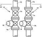
各集砂弁は、図14に示すように、流量調整弁Vaと切換弁Vbとを直列に接続してなっている。流量調整弁Va及び切換弁Vbは、流量調整弁Vaの流量調整時及び切換弁Vbの故障時には、それぞれの弁体に接続されている被回転部材、例えば、流量調整弁及び切換弁がボール弁である場合は弁体であるボールb1,b2に接続されているステムS1,S2を、例えばレンチなどで強制的に回転する必要があるが、従来の集砂弁群は、図13に示すように、回転力を加える被回転部材(S1,S2)を、管路の整列方向Lに対して直角(θ1)方向に向けて(図12及び図13を参照)、しかも、全ての集砂弁を共通の高さに取り付けていた。図12〜14において、Mは切換弁Vbを通水状態又は止水状態にするモータである。 As shown in FIG. 14, each sand collecting valve has a flow rate adjusting valve Va and a switching valve Vb connected in series. When the flow rate adjustment valve Va and the switching valve Vb are adjusted, or when the switching valve Vb fails, the flow rate adjusting valve Va and the switching valve Vb are rotated members connected to the respective valve bodies, for example, the flow rate adjusting valve and the switching valve are ball valves. In this case, it is necessary to forcibly rotate the stems S1, S2 connected to the balls b1, b2, which are valve bodies, with, for example, a wrench. A conventional sand collecting valve group is as shown in FIG. In addition, the members to be rotated (S1, S2) to which the rotational force is applied are directed in the direction (θ1) perpendicular to the pipe alignment direction L (see FIGS. 12 and 13), and all the sand collecting valves Were attached to a common height. 12-14, M is a motor which makes the switching valve Vb pass a water state or a water stop state.
図11には示されていないが、紙面手前側に存在する沈砂池の底面の領域(B1, B3,B5,B7)に対して設置されたノズルヘッダー(H1, H3,H5,H7)のそれぞれを図外の共通の給水ポンプに結合する管路(P1,P3,P5,P7)にも、流量調整弁Vaと切換弁Vbを直列に接続してなる集砂弁V1,V3,V5,V7が取り付けられている。 Although not shown in FIG. 11, each of the nozzle headers (H1, H3, H5, H7) installed for the bottom area (B1, B3, B5, B7) of the sand basin existing on the front side of the page. Are connected to a common water pump (not shown) (P1, P3, P5, P7) and sand collecting valves V1, V3, V5, V7 formed by connecting a flow rate adjusting valve Va and a switching valve Vb in series. Is attached.
従って、図12に例示するように、いずれかの流量調整弁Vaの流量調整を行うために調整工具T、例えばレンチを流量調整弁Vaの被回転部材、例えばボール弁のステムS1に装着すると(図14のTを参照)、通常のレンチの長さは一例として750mmであるため、そのレンチの回動範囲内に隣の流量調整弁Vaが存在してその流量調整作業が妨害されるという問題があった。切換弁Vbの故障発生時にその被回転部材に修理工具を装着する場合も同様の問題があった。 Accordingly, as illustrated in FIG. 12, in order to adjust the flow rate of one of the flow rate adjusting valves Va, an adjustment tool T, for example, a wrench, is attached to a rotated member of the flow rate adjusting valve Va, for example, the stem S1 of the ball valve ( Since the length of a normal wrench is 750 mm as an example, there is a problem that an adjacent flow rate adjustment valve Va exists in the rotation range of the wrench and the flow rate adjustment operation is hindered. was there. The same problem occurs when a repair tool is mounted on the rotated member when the switching valve Vb fails.
上記問題を解決するためには、各集砂弁を取付ける管路を屈曲して、隣り合う集砂弁の間隔(図13のD)を広めるとか、各集砂弁の取付高さを交互に変えるとかが考えられるが、このような管路の屈曲や取付高さの交互変更などは、部材コスト又は加工コスト及び施工コストの増加を招き、施工も煩雑になる難点がある。 In order to solve the above problems, the pipe line for attaching each sand collecting valve is bent to widen the interval between adjacent sand collecting valves (D in FIG. 13), or the height of mounting each sand collecting valve alternately. Although it is conceivable to change it, such bending of the pipe line or alternation of the mounting height causes an increase in member cost, processing cost, and construction cost, and there is a problem that construction becomes complicated.
本発明は、上記の事情に鑑みてなされたものであり、その目的は、部材コスト又は加工コスト及び施工コストの増加を招くことなく、従来と同様の施工により集砂弁群の取り付けが可能で、しかも、隣の集砂弁に妨害されることなく、円滑に流量調整弁の調整作業又は切換弁の修理作業を行うことができる集砂弁取付構造を備えた集砂装置を提供することにある。 The present invention has been made in view of the above circumstances. The purpose of the present invention is to allow the sand collecting valve group to be attached by the same construction as before without causing an increase in member cost, processing cost, and construction cost. In addition, the present invention provides a sand collecting device having a sand collecting valve mounting structure that can smoothly adjust a flow rate adjusting valve or repair a switching valve without being obstructed by an adjacent sand collecting valve. is there.
本発明は、上記の目的を達成するため、底部に集砂ピットを備えた沈砂池と、複数個のノズルを等間隔をもって有し、前記沈砂池の底面を複数に区分した各領域のそれぞれに設置されたノズルヘッダーと、それらのノズルヘッダーに水を供給する給水ポンプと、前記ノズルヘッダーのそれぞれと前記給水ポンプとを結合する管路であって、整列させた状態で前記沈砂池の上方を覆う天井壁に設けた孔に貫通されたものと、前記管路のそれぞれに略同じ高さにおいて取付けられた、前記ノズルヘッダーへの給水量を調整する流量調整弁と通水・止水を行なう切換弁とを結合してなる集砂弁群とを備え、前記沈砂池の底面に堆積した砂を前記ノズルヘッダーのノズルより噴射される水により流して前記集砂ピットに集める沈砂池の集砂装置において、集砂弁群の各集砂弁の流量調整弁の弁体及び切換弁の弁体に接続された被回転部材の軸線を前記管路の整列方向に対して所定角度傾斜させて取付けたことを特徴としている。
前記所定の傾斜角度は、30〜60度であることが望ましく、とくに45度が最も好ましい。
In order to achieve the above object, the present invention has a sand basin provided with a sand collecting pit at the bottom, and a plurality of nozzles at equal intervals, and each of the regions where the bottom surface of the sand basin is divided into a plurality of areas. Nozzle headers installed, water supply pumps for supplying water to the nozzle headers, and pipelines for connecting each of the nozzle headers and the water supply pump, covering the top of the sand basin in an aligned state A flow rate adjusting valve that adjusts the amount of water supplied to the nozzle header, and a switch that performs water flow and water stoppage, which are attached to each of the pipe lines at substantially the same height, and those that are penetrated through holes provided in the ceiling wall A sand collection device comprising: a sand collection valve group formed by combining a valve, and collecting sand accumulated on a bottom surface of the sand settling basin with water sprayed from a nozzle of the nozzle header and collecting it in the sand collection pit smell The axis of the rotated member connected to the valve body of the flow regulating valve and the switching valve of each sand collecting valve of the sand collecting valve group is inclined at a predetermined angle with respect to the alignment direction of the pipes. It is characterized by.
The predetermined inclination angle is preferably 30 to 60 degrees, and most preferably 45 degrees.
本発明によれば、各集砂弁の流量調整弁及び切換弁の弁体に接続された被回転部材の軸線を管路の整列方向に対して所定角度傾斜させて取付けたので、一つの流量調整弁又は切換弁の被回転部材を流量調整用工具により回転して流量調整作業を行なう場合、又は修理工具により修理作業を行なう場合に、隣りの流量調整弁又は切換弁により妨害されることなく、円滑に流量調整作業又は修理作業を行なうことができる。また、集砂弁間距離を従来よりも狭くすることができるから、沈砂池の天井壁に設ける孔の大きさを小さくすることができる。さらに、流量調整作業又は修理作業を容易にするために管路の曲げ加工等を必要としないので、部材コスト又は製造コスト及び施工コストの低減が可能である。
傾斜角度を30〜60度とした場合は、汎用性のある安価な集砂弁を用いることができる。
According to the present invention, the axis of the rotated member connected to the valve body of the flow rate adjusting valve and the switching valve of each sand collecting valve is attached to be inclined at a predetermined angle with respect to the alignment direction of the pipe line. When the flow rate adjustment work is performed by rotating the rotating member of the adjustment valve or the switching valve with the flow adjustment tool, or when the repair work is performed with the repair tool, it is not obstructed by the adjacent flow adjustment valve or the changeover valve. Therefore, the flow rate adjustment work or the repair work can be performed smoothly. Further, since the distance between the sand collecting valves can be made smaller than before, the size of the hole provided in the ceiling wall of the sand basin can be reduced. Furthermore, since it is not necessary to bend the pipe line in order to facilitate the flow rate adjustment work or the repair work, it is possible to reduce the member cost, the manufacturing cost, and the construction cost.
When the inclination angle is 30 to 60 degrees, a versatile and inexpensive sand collecting valve can be used.
次に、本発明を終末処理場のポンプ場における雨水処理設備に適用した場合の実施の形態について、図面を用いて説明する。 Next, an embodiment when the present invention is applied to a rainwater treatment facility at a pumping station of a terminal treatment plant will be described with reference to the drawings.
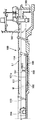
図1に示すように、雨水処理設備100は、沈砂池101とポンプ井102とを有する。図1の左側にある流入渠(不図示)の下流側にゲート104Aを介して沈砂池101が接続され、その沈砂池の下流側にポンプ井102が接続されている。前記ゲート104Aは、沈砂池101の上流側に設置されて、沈砂池への雨水の流入を許容したり、阻止したりするものである。ポンプ井102には排水ポンプ103Aが備えてある。
As shown in FIG. 1, the
沈砂池101の底部101bの中央には最深位置に集砂ピット105が形成され、沈砂池101の底面は沈砂池101を画成する側壁W1の下端部から集砂ピット105側が深くなるように傾斜して形成されており、その沈砂池101の底部の幅方向(水流方向に直角な方向)中央部に沈砂池101の上流側端部から集砂ピット105までと、沈砂池101の下流側端部から集砂ピット105までそれぞれ集砂ピット105側が深くなるように傾斜する主トラフ106が形成されている。また、両側の側壁W1から集砂ピット105まで下り傾斜する斜面(以下、集砂ピット斜面という。)107が形成されている。
A
そして、主トラフ106及び集砂ピット斜面107によって、沈砂池101の底面101bは4つの領域に区分されている。各領域の底部の表面には、側壁W1側から主トラフ106に向けて等間隔をもって平行に延びる多数の小トラフ108が形成されている。
The
図示の実施の形態においては、底面101bの各領域は、さらにそれぞれ2つずつの領域に分割されて、図6及び図8に示すように、全部で8つの領域B1〜B8を有している。領域数は、後述される給水ポンプ103B及び揚砂ポンプ103Cの能力に応じて任意に設定することができる。
In the illustrated embodiment, each region of the
そして、図2及び図5に示すように、沈砂池101の底面101bの各領域B1〜B8の上方には、側壁W1の近傍においてノズルヘッダーH1〜H8が設置されている。各ノズルヘッダーH1〜H8は、いずれも同様に構成されていて、母管109に複数のノズル110を等間隔に取付けてなっている。
As shown in FIGS. 2 and 5, nozzle headers H <b> 1 to H <b> 8 are installed in the vicinity of the side wall W <b> 1 above the regions B <b> 1 to B <b> 8 of the
ノズル110は、いずれも同一の種類と形状のものが使用され、図7に示すように、その噴射口110aは小トラフ108の間の底面に均等に散水されるように所定寸法の長円形に形成されている。また、個々のノズル110から噴射される水が隣接するノズルからの水と衝突して互いに干渉することにより、底部の洗浄機能を損なわないように、各ノズル110がそれぞれ小トラフ108の間の底面の直近上方に所定間隔を持って配設されている。
The
各ノズルヘッダーH1〜H8には、これをポンプ井102に設置されている給水ポンプ103Bに結合するための管P1〜P8の一端が接続され、その管P1〜P8は側壁W1の近傍を経て、沈砂池101の上面を覆う天井壁W2の隣り合う補強材111の間においてその天井壁W2に形成した細長い孔112の直前に集合され、その集合された管P1〜P8を整列させた状態で前記孔112に貫通して天井壁W2の上方まで延長され、その管P1〜P8の他端部は給水ポンプ103Bに接続されている給水管P13に結合されている。そして、天井壁W2の上方まで延長して整列されている管P1〜P8のそれぞれに集砂弁V1〜V8が同じ高さに取付けられている。
Each nozzle header H1 to H8 is connected to one end of pipes P1 to P8 for coupling the nozzle headers H1 to H8 to the
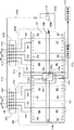
図5及び図8の上側の左には、図6の領域B2,B4のノズルヘッダーH2,H4と領域B1,B3のノズルヘッダーH1,H3に対応する集砂弁V1,V2,V3,V4により構成された第1の集砂弁群VG1が示され、図5及び図8の上側の右には、図6の領域B6,B8のノズルヘッダーH6,H8と領域B5,B7のノズルヘッダーH5,H7に対応する集砂弁V5,V6,V7,V8により構成された第2の集砂弁群VG2が示されている。 5 and 8, the left side of the upper side of the nozzle headers H2, H4 in the regions B2, B4 and the sand collecting valves V1, V2, V3, V4 corresponding to the nozzle headers H1, H3 in the regions B1, B3 in FIG. The constructed first sand collecting valve group VG1 is shown. On the upper right side of FIGS. 5 and 8, nozzle headers H6 and H8 in the regions B6 and B8 in FIG. 6 and nozzle headers H5 and B5 in the regions B5 and B7, A second sand collecting valve group VG2 constituted by sand collecting valves V5, V6, V7, V8 corresponding to H7 is shown.
いずれの集砂弁V1〜V8も同じ構成を有する。すなわち、給水ポンプ103Bからの圧力水の個々のノズルヘッダーH1〜H8への流量を調整するための流量調整弁Vaと個々のノズルヘッダーH1〜H8への通水・止水を行なう切換弁Vbとを直結して構成されている。流量調整弁Vaには、流量が多いので、流量調整を手作業で行なう手動弁、例えば、ボール弁が用いられている。そして、いずれの流量調整弁Va及び切換弁Vbも、弁体に流量調整工具、例えばレンチ等により回転力を加えるための被回転部材(例えば、ボール弁の場合はステムS1,S2)の回転軸線を、図9ないし図11に示すように、管P1〜P8の整列方向Lに対して所定角度(θ2)傾けて取付けられている。
All the sand collecting valves V1 to V8 have the same configuration. That is, a flow rate adjusting valve Va for adjusting the flow rate of the pressure water from the
上記管の整列方向Lに対して傾斜させる角度θ2は、一つの流量調整弁Vaの流量調整作業及び切換弁Vbの修理作業が隣りの流量調整弁Va又は切換弁Vbにより妨害されない角度に設定される。流量調整弁Vaの種類により多少の変動はあるが、汎用の手動弁の場合は、その固定用フランジに設けられるボルト貫通孔の数が8個であるので、前記傾斜角度は45度となる。 The angle θ2 to be inclined with respect to the tube alignment direction L is set to an angle at which the flow rate adjusting operation of one flow rate adjusting valve Va and the repairing operation of the switching valve Vb are not hindered by the adjacent flow rate adjusting valve Va or the switching valve Vb. The Although there are some fluctuations depending on the type of the flow rate adjusting valve Va, in the case of a general-purpose manual valve, the number of bolt through holes provided in the fixing flange is eight, so the inclination angle is 45 degrees.
このように、各流量調整弁Vaを管路P1〜P8の整列方向Lに対して所定角度傾けて取り付けた場合は、図10に一点鎖線で示すように、流量調整工具T、例えばレンチ等を被回転部材(S1)に嵌合又は係合して回転して流量調整作業を行なうときに、隣りの流量調整弁Va又は切換弁Vbによりその流量調整作業が妨害されることがないという格別の効果が得られる。切換弁Vbの修理作業を行なうときも、同様に隣りの流量調整弁Va又は切換弁Vbによりその流量調整作業が妨害されることがない。 As described above, when each flow rate adjusting valve Va is attached at a predetermined angle with respect to the alignment direction L of the pipes P1 to P8, a flow rate adjusting tool T, for example, a wrench or the like is used, as shown by a dashed line in FIG. When the flow adjustment operation is performed by fitting or engaging with the rotated member (S1) and rotating, the flow adjustment operation is not obstructed by the adjacent flow adjustment valve Va or the switching valve Vb. An effect is obtained. Similarly, when the repair work of the switching valve Vb is performed, the flow rate adjusting work is not obstructed by the adjacent flow rate adjusting valve Va or the switching valve Vb.
従って、管P1〜P8の設置間隔を従来よりも狭めることができ、これに伴い、天井壁W2に設ける長孔の長さを短くすることができるから、補強材111間の距離を気にすることなく管P1〜P8の設置ができる。また、天井壁の加工数を減らすことができる。
Therefore, the installation interval of the pipes P1 to P8 can be made narrower than before, and accordingly, the length of the long hole provided in the ceiling wall W2 can be shortened, so the distance between the reinforcing
主トラフ106の最も高い位置、すなわち、主トラフの上流側端部及び下流側端部にも、それぞれノズル110a,110bが設けられ、それぞれのノズルに一端が接続されている管P9,P10は、天井壁W2の孔112の下側でノズルヘッダーH1〜H4,H5〜H8の管P1〜P4,P5〜P8とそれぞれ集合され、同様に孔112の上方に貫通され、その管P9,P10に集砂弁V9,V10が他の集砂弁V1〜V4, V5〜V8と同様に取付けられて、第1及び第2の集砂弁群VG1,VG2にそれぞれ並設されている。
Pipes P9 and P10, in which
横トラフ107の両端部にもノズル110cが設けられ、そのノズルに一端が接続されている管P11は、天井壁W2の孔112の下側で管P5〜P8,P10と集合され、同様に孔112の上方に貫通され、その管P11に集砂弁V11が他の集砂弁V5〜V8,V10と同様に管の整列方向に対して所定角度(θ2)傾けて取付けられて、第2の集砂弁群VG2に並設されている。
The
図5及び図8の110dは、集砂ピット105内の砂を撹拌して流動化させるためのノズルであり、他のノズルの場合と同様に一端が接続された管P12がW2の孔112から上方に貫通され、その管P12に集砂弁V12が同様に管の整列方向Lに対して所定角度(θ2)傾けて取付けられて、第2の集砂弁群VG2に並設されている。
110d in FIGS. 5 and 8 is a nozzle for agitating and fluidizing the sand in the
主トラフ用ノズルの管P11及び集砂ピット撹拌用ノズルの管P12は、第1群VG1と第2群VG2のいずれに並設されても良い。 The main trough nozzle pipe P11 and the sand collecting pit stirring nozzle pipe P12 may be arranged in parallel in either the first group VG1 or the second group VG2.
上記各ノズルヘッダーの集砂弁については、試運転の際に、順次切換弁Vbを通水側に駆動するとともに、流量調整弁Vaの被回転部材を流量調整工具により回転して、各ノズルからの各領域での噴射水量が均等になるように流量調整が行なわれる。このような流量調整は、運転後も各ノズルヘッダーのノズルの噴射状態を監視して必要な時にも行うことができる。 Regarding the sand collecting valves of the nozzle headers, during the trial operation, the switching valve Vb is sequentially driven to the water side, and the rotated member of the flow rate adjusting valve Va is rotated by the flow rate adjusting tool to The flow rate is adjusted so that the amount of jet water in each region is uniform. Such flow rate adjustment can be performed even when necessary by monitoring the injection state of the nozzles of each nozzle header.
なお、沈砂池101の上流側直前には、夾雑物排除のための自動スクリーン113が設けられており、この自動スクリーン113により、例えば浮上物、水中浮遊物、小石や礫等の夾雑物が捕捉され、コンベアなどにより自動的に取り除かれる。また、沈砂池101の下流側端部には図1に示すように、濾過機114が設けられている。
In addition, an
図1及び図8の103Bは、ポンプ井102に設けられた給水ポンプであり、この実施の形態においては、この給水ポンプ103Bを稼動することにより、ポンプ井102内の水を集砂装置の前記ノズルヘッダーH1〜H8に供給する。
103B of FIG.1 and FIG.8 is the feed water pump provided in the pump well 102, In this embodiment, by operating this
給水ポンプ103Bには、図8に示すように、リリーフ回路P14が設けられ、そのリリーフ回路P14に取付けられた切換弁116を開けることにより、給水ポンプ103Bからの水を沈砂池101に移送することができる。
As shown in FIG. 8, the water supply pump 103 </ b> B is provided with a relief circuit P <b> 14, and the water from the water supply pump 103 </ b> B is transferred to the
給水ポンプ103Bからの水は、給水管P13を経て各集砂弁群VG1,VG2に供給され、図示されていないマイクロコンピュータによる制御により各集砂弁V1〜V12が所定の順序で駆動されて、所定のノズルヘッダーH1〜H8へ順次給水され、かつ、各トラフのノズル110a,110b及び撹拌用ノズル110cに給水されて、沈砂池101での集砂動作が行なわれる。
Water from the
揚砂ポンプ103Cは、沈砂池内に滞留する水の水面が集砂ピット105内に位置する排水状態を維持するように稼動するものであって、集砂ピット内の水面が所定の高水位以上のときは自動的に運転を開始し、集砂ピット内の水面が所定の低水位よりも低くなると、運転が自動的に止まるものである。
The
上記構成による集砂動作は、上記特許文献1に記載されているものと同一であり、また、本発明の要部と直接関係が無いので、ここでは詳述しない。
The sand collecting operation according to the above configuration is the same as that described in
100 雨水処理設備
101 沈砂池
101a 沈砂池の底部
103A 排水ポンプ
103B 滞留水ポンプ
103C 揚砂ポンプ
105 集砂ピット
P1〜P8 管路
H1〜H8 ノズルヘッダー
110,110a〜110d ノズル
VG1,VG2 集砂弁群
V1〜V8 集砂弁
Va 流量調整弁
Vb 切換弁
M 被回転部材
W1 沈砂池の側壁
W2 沈砂池の天井壁
112 天井壁に設けた長孔
DESCRIPTION OF
Claims (2)
前記集砂弁群の各集砂弁を、その流量調整弁及び切換弁の弁体に接続された被回転部材の軸線を前記管路の整列方向に対して所定角度傾けて取付けたことを特徴とする沈砂池の集砂装置。 A sand basin having a sand collecting pit at the bottom, a plurality of nozzles, nozzle headers installed in each of the areas where the bottom surface of the sand basin is divided into a plurality, and supplying water to these nozzle headers A water supply pump, a pipe line connecting each of the nozzle headers and the water supply pump, wherein the pipe line is penetrated through a hole provided in a ceiling wall covering the top of the sand basin in an aligned state; A flow rate adjusting valve for adjusting the amount of water supplied to the nozzle header, and a switching valve for passing water to and stopping water from the nozzle header, which are attached to each of them at substantially the same height above the ceiling wall, are directly connected. In the sand collecting device of the sand basin, the sand collected on the bottom surface of the sand basin is collected by the water sprayed from the nozzle of the nozzle header and collected in the sand collecting pit.
Each sand collecting valve of the sand collecting valve group is attached by tilting the axis of the rotated member connected to the valve body of the flow rate adjusting valve and the switching valve at a predetermined angle with respect to the alignment direction of the pipes. A sand collecting device for a sand basin.
Priority Applications (1)
| Application Number | Priority Date | Filing Date | Title |
|---|---|---|---|
| JP2010119369A JP5578552B2 (en) | 2010-05-25 | 2010-05-25 | Sand collector |
Applications Claiming Priority (1)
| Application Number | Priority Date | Filing Date | Title |
|---|---|---|---|
| JP2010119369A JP5578552B2 (en) | 2010-05-25 | 2010-05-25 | Sand collector |
Related Child Applications (1)
| Application Number | Title | Priority Date | Filing Date |
|---|---|---|---|
| JP2014136777A Division JP5879602B2 (en) | 2014-07-02 | 2014-07-02 | Fluid supply device |
Publications (2)
| Publication Number | Publication Date |
|---|---|
| JP2011245386A JP2011245386A (en) | 2011-12-08 |
| JP5578552B2 true JP5578552B2 (en) | 2014-08-27 |
Family
ID=45411307
Family Applications (1)
| Application Number | Title | Priority Date | Filing Date |
|---|---|---|---|
| JP2010119369A Active JP5578552B2 (en) | 2010-05-25 | 2010-05-25 | Sand collector |
Country Status (1)
| Country | Link |
|---|---|
| JP (1) | JP5578552B2 (en) |
Families Citing this family (2)
| Publication number | Priority date | Publication date | Assignee | Title |
|---|---|---|---|---|
| CN109490015A (en) * | 2018-11-02 | 2019-03-19 | 河海大学 | It is a kind of for preventing the bed-sit sampler of turbulent water in high-velocity flow environment |
| CN112237759A (en) * | 2020-11-23 | 2021-01-19 | 上海勘测设计研究院有限公司 | Sand washing device for sand basin and use method thereof |
Family Cites Families (13)
| Publication number | Priority date | Publication date | Assignee | Title |
|---|---|---|---|---|
| JPS55145777U (en) * | 1979-04-06 | 1980-10-20 | ||
| JPS5839562B2 (en) * | 1979-10-22 | 1983-08-31 | 日立プラント建設株式会社 | Siphon type mud collecting machine |
| JPS58137173U (en) * | 1982-03-12 | 1983-09-14 | タカラ工業株式会社 | valve control device |
| JPH0473474A (en) * | 1990-07-12 | 1992-03-09 | Maoka Sekkei:Kk | Sequential open/close construction of lever type open/ close valve |
| JPH0542844U (en) * | 1991-11-08 | 1993-06-11 | 東邦瓦斯株式会社 | Gascoque |
| JPH0614653U (en) * | 1992-07-29 | 1994-02-25 | 鐘紡株式会社 | Hot water supply device |
| JP3054528B2 (en) * | 1993-12-17 | 2000-06-19 | 株式会社巴技術研究所 | Drive device for center type butterfly valve |
| JP3540868B2 (en) * | 1995-09-12 | 2004-07-07 | 株式会社イーエス・ウォーターネット | Sand collecting nozzle device |
| JP3122391B2 (en) * | 1997-07-01 | 2001-01-09 | 三菱重工業株式会社 | Multi-valve interlocking switching device |
| JP2004122042A (en) * | 2002-10-04 | 2004-04-22 | Hitachi Metals Ltd | Grit collecting/pumping apparatus |
| JP4503467B2 (en) * | 2005-02-28 | 2010-07-14 | 株式会社日立プラントテクノロジー | Sanding system |
| JP4827079B2 (en) * | 2005-11-14 | 2011-11-30 | アクアインテック株式会社 | Ozone treatment equipment |
| JP4558677B2 (en) * | 2006-05-18 | 2010-10-06 | 住友重機械エンバイロメント株式会社 | Sand collection equipment and sand collection method |
-
2010
- 2010-05-25 JP JP2010119369A patent/JP5578552B2/en active Active
Also Published As
| Publication number | Publication date |
|---|---|
| JP2011245386A (en) | 2011-12-08 |
Similar Documents
| Publication | Publication Date | Title |
|---|---|---|
| JP3315489B2 (en) | Sand collection method and device for sand basin | |
| CN112282033B (en) | Auxiliary drainage system for iron ore construction prevention and water control | |
| JP3708442B2 (en) | Sand collection device for sand basin | |
| JP5578552B2 (en) | Sand collector | |
| JP2013202570A (en) | Sand collection nozzle and sand collection nozzle device | |
| JP5704593B2 (en) | Sand basin structure | |
| JP6083656B2 (en) | Sand collection method for sand basin | |
| JP6304791B2 (en) | Installation structure of pipe for collecting sand in a sand basin | |
| JP6142308B2 (en) | Installation structure of pipe for collecting sand in a sand basin | |
| JP2020114590A (en) | Sand collecting device in sedimentation basin | |
| JP7577380B2 (en) | Grit chamber | |
| JP5879602B2 (en) | Fluid supply device | |
| JP6521409B2 (en) | Sand collecting equipment in settling basin | |
| JP6715407B2 (en) | Sand collector in a sand basin | |
| JP6727027B2 (en) | Sand removal equipment for sand basins | |
| JP5953493B2 (en) | Sedimentation basin sand removal device and sand removal method | |
| JP6310114B2 (en) | Sand collection device for sand basin | |
| JP5678321B2 (en) | Sand collection device for sand basin | |
| JP6142309B2 (en) | Sand collection device for sand basin | |
| JP6924520B2 (en) | Sand collecting device for sand basin | |
| CN223088463U (en) | Civil engineering foundation ditch drainage structures | |
| JP6862018B2 (en) | Contamination removal screen device | |
| JP7120606B2 (en) | sand pond | |
| JP6531287B2 (en) | Sedimentation basin collecting equipment | |
| JP2016093813A5 (en) |
Legal Events
| Date | Code | Title | Description |
|---|---|---|---|
| A621 | Written request for application examination |
Free format text: JAPANESE INTERMEDIATE CODE: A621 Effective date: 20130412 |
|
| A977 | Report on retrieval |
Free format text: JAPANESE INTERMEDIATE CODE: A971007 Effective date: 20140521 |
|
| TRDD | Decision of grant or rejection written | ||
| A01 | Written decision to grant a patent or to grant a registration (utility model) |
Free format text: JAPANESE INTERMEDIATE CODE: A01 Effective date: 20140604 |
|
| A61 | First payment of annual fees (during grant procedure) |
Free format text: JAPANESE INTERMEDIATE CODE: A61 Effective date: 20140702 |
|
| R150 | Certificate of patent or registration of utility model |
Ref document number: 5578552 Country of ref document: JP Free format text: JAPANESE INTERMEDIATE CODE: R150 |
|
| R250 | Receipt of annual fees |
Free format text: JAPANESE INTERMEDIATE CODE: R250 |
|
| R250 | Receipt of annual fees |
Free format text: JAPANESE INTERMEDIATE CODE: R250 |
|
| R250 | Receipt of annual fees |
Free format text: JAPANESE INTERMEDIATE CODE: R250 |
|
| R250 | Receipt of annual fees |
Free format text: JAPANESE INTERMEDIATE CODE: R250 |
|
| R250 | Receipt of annual fees |
Free format text: JAPANESE INTERMEDIATE CODE: R250 |
|
| R250 | Receipt of annual fees |
Free format text: JAPANESE INTERMEDIATE CODE: R250 |
|
| R250 | Receipt of annual fees |
Free format text: JAPANESE INTERMEDIATE CODE: R250 |
|
| R250 | Receipt of annual fees |
Free format text: JAPANESE INTERMEDIATE CODE: R250 |
|
| R250 | Receipt of annual fees |
Free format text: JAPANESE INTERMEDIATE CODE: R250 |