JP5576664B2 - Focus detection apparatus and method - Google Patents
Focus detection apparatus and method Download PDFInfo
- Publication number
- JP5576664B2 JP5576664B2 JP2010011373A JP2010011373A JP5576664B2 JP 5576664 B2 JP5576664 B2 JP 5576664B2 JP 2010011373 A JP2010011373 A JP 2010011373A JP 2010011373 A JP2010011373 A JP 2010011373A JP 5576664 B2 JP5576664 B2 JP 5576664B2
- Authority
- JP
- Japan
- Prior art keywords
- pair
- signal
- focus detection
- block
- distance measuring
- Prior art date
- Legal status (The legal status is an assumption and is not a legal conclusion. Google has not performed a legal analysis and makes no representation as to the accuracy of the status listed.)
- Expired - Fee Related
Links
Images


Classifications
-
- G—PHYSICS
- G03—PHOTOGRAPHY; CINEMATOGRAPHY; ANALOGOUS TECHNIQUES USING WAVES OTHER THAN OPTICAL WAVES; ELECTROGRAPHY; HOLOGRAPHY
- G03B—APPARATUS OR ARRANGEMENTS FOR TAKING PHOTOGRAPHS OR FOR PROJECTING OR VIEWING THEM; APPARATUS OR ARRANGEMENTS EMPLOYING ANALOGOUS TECHNIQUES USING WAVES OTHER THAN OPTICAL WAVES; ACCESSORIES THEREFOR
- G03B13/00—Viewfinders; Focusing aids for cameras; Means for focusing for cameras; Autofocus systems for cameras
- G03B13/32—Means for focusing
- G03B13/34—Power focusing
- G03B13/36—Autofocus systems
-
- G—PHYSICS
- G02—OPTICS
- G02B—OPTICAL ELEMENTS, SYSTEMS OR APPARATUS
- G02B7/00—Mountings, adjusting means, or light-tight connections, for optical elements
- G02B7/28—Systems for automatic generation of focusing signals
-
- H—ELECTRICITY
- H04—ELECTRIC COMMUNICATION TECHNIQUE
- H04N—PICTORIAL COMMUNICATION, e.g. TELEVISION
- H04N23/00—Cameras or camera modules comprising electronic image sensors; Control thereof
- H04N23/60—Control of cameras or camera modules
- H04N23/67—Focus control based on electronic image sensor signals
- H04N23/672—Focus control based on electronic image sensor signals based on the phase difference signals
-
- H—ELECTRICITY
- H04—ELECTRIC COMMUNICATION TECHNIQUE
- H04N—PICTORIAL COMMUNICATION, e.g. TELEVISION
- H04N25/00—Circuitry of solid-state image sensors [SSIS]; Control thereof
- H04N25/50—Control of the SSIS exposure
- H04N25/57—Control of the dynamic range
- H04N25/58—Control of the dynamic range involving two or more exposures
- H04N25/581—Control of the dynamic range involving two or more exposures acquired simultaneously
- H04N25/583—Control of the dynamic range involving two or more exposures acquired simultaneously with different integration times
-
- H—ELECTRICITY
- H04—ELECTRIC COMMUNICATION TECHNIQUE
- H04N—PICTORIAL COMMUNICATION, e.g. TELEVISION
- H04N25/00—Circuitry of solid-state image sensors [SSIS]; Control thereof
- H04N25/70—SSIS architectures; Circuits associated therewith
- H04N25/71—Charge-coupled device [CCD] sensors; Charge-transfer registers specially adapted for CCD sensors
- H04N25/75—Circuitry for providing, modifying or processing image signals from the pixel array
-
- H—ELECTRICITY
- H04—ELECTRIC COMMUNICATION TECHNIQUE
- H04N—PICTORIAL COMMUNICATION, e.g. TELEVISION
- H04N25/00—Circuitry of solid-state image sensors [SSIS]; Control thereof
- H04N25/70—SSIS architectures; Circuits associated therewith
- H04N25/76—Addressed sensors, e.g. MOS or CMOS sensors
- H04N25/77—Pixel circuitry, e.g. memories, A/D converters, pixel amplifiers, shared circuits or shared components
- H04N25/771—Pixel circuitry, e.g. memories, A/D converters, pixel amplifiers, shared circuits or shared components comprising storage means other than floating diffusion
Description
本発明は、カメラ等の撮像装置において用いられる焦点検出装置及び方法に関する。 The present invention relates to a focus detection apparatus and method used in an imaging apparatus such as a camera.
従来、カメラの自動焦点検出装置において用いられる焦点検出方法として、位相差検出方式が良く知られている。位相差検出方式は、撮影レンズの異なる射出瞳領域を通過した被写体からの光束を、一対のラインセンサ上に結像させ、光電変換して得られた被写体像の一対の電気信号の位相差を求めることで、撮影レンズのデフォーカス量を検出する方式である。 Conventionally, a phase difference detection method is well known as a focus detection method used in an automatic focus detection device of a camera. In the phase difference detection method, a light flux from a subject that has passed through different exit pupil regions of the photographing lens is imaged on a pair of line sensors, and the phase difference between a pair of electrical signals of the subject image obtained by photoelectric conversion is calculated. This is a method of detecting the defocus amount of the taking lens by obtaining.
また、ラインセンサを複数のブロックに分割して、ブロック毎に信号蓄積制御を行い、各ブロックの位置に対応した複数の被写体像から、デフォーカス量の検出を行う多点焦点検出装置についての技術も開示されている(例えば、特許文献1参照)。 Also, a technique for a multipoint focus detection device that divides a line sensor into a plurality of blocks, performs signal accumulation control for each block, and detects a defocus amount from a plurality of subject images corresponding to the position of each block. Is also disclosed (see, for example, Patent Document 1).
しかしながら、特許文献1に記載された焦点検出装置では、各ブロックの視野長が短い。視野長が短くなると、被写体のコントラストが十分に補足できない場合があるため、合焦精度が低下してしまうという問題があった。また、検出可能なデフォーカス範囲が狭くなるため、大きくデフォーカスしている被写体については合焦制御不能になってしまうという問題が生じる。
However, in the focus detection apparatus described in
本発明は上記問題点を鑑みてなされたものであり、ラインセンサを複数のブロックに分割してブロック毎に蓄積制御する機能を有する焦点検出装置において、焦点検出精度の低下を回避できるようにすることを目的とする。 The present invention has been made in view of the above problems, and in a focus detection apparatus having a function of dividing and controlling accumulation of a line sensor into a plurality of blocks, a decrease in focus detection accuracy can be avoided. For the purpose.
上記目的を達成するために、撮影レンズの異なる射出瞳領域を通過した被写体からの一対の光束の位相差に基づいて前記撮影レンズの焦点状態を検出する本発明の焦点検出装置は、前記被写体からの一対の光束を光電変換して、電気信号を出力する光電変換手段と、複数の測距点のいずれかを選択する選択手段と、前記光電変換手段から電気信号を読み出す際に、複数の異なるパターンで、前記複数の測距点にそれぞれ対応する複数のブロック対に分けて読み出すと共に、前記ブロック対毎に、該ブロック対の電気信号のレベルが焦点検出に適したレベルになると、前記光電変換手段から電気信号を読み出すように制御する制御手段と、前記ブロック対毎に読み出された電気信号を記憶する、前記複数のパターンにそれぞれ対応した複数のフレームメモリと、前記複数のフレームメモリに記憶された電気信号の内、前記選択手段により選択された測距点に対応するブロック対の電気信号の位相差に基づいて、前記撮影レンズの焦点状態を検出する焦点検出手段とを有し、前記制御手段は、各ブロック対の電気信号の最大信号と最小信号との差が予め設定された値よりも大きくなった場合、及び、前記最小信号が予め設定された値よりも大きくなった場合に、前記ブロック対の電気信号のレベルが焦点検出に適したレベルになったと判断する。 In order to achieve the above object, the focus detection apparatus of the present invention for detecting the focus state of the photographing lens based on the phase difference of a pair of light beams from the subject that has passed through different exit pupil regions of the photographing lens includes: a pair of a light beam and photoelectrically converted, and when reading out the photoelectric conversion means for outputting an electrical signal, and selecting means for selecting one of several distance measuring point, the electrical signal from said photoelectric conversion means, a plurality under different such Rupa turn, it reads in a plurality of blocks pairs corresponding to the plurality of distance measuring points, before each Chivu lock pair, the level of the level of the electric signal of the block pair is suitable for focus detection When becomes, and control means for controlling so as to read an electrical signal from said photoelectric conversion means, for storing the electrical signals read out in each of the block pairs, a plurality of off respectively corresponding to said plurality of patterns A focus state of the photographing lens is detected based on a phase difference between a pair of blocks corresponding to a distance measuring point selected by the selection unit among the electric signals stored in the frame memory and the plurality of frame memories. A focus detection unit that performs control, and the control unit sets the minimum signal when the difference between the maximum signal and the minimum signal of the electrical signal of each block pair is greater than a preset value. When the value is larger than the determined value, it is determined that the level of the electric signal of the block pair has become a level suitable for focus detection.
本発明によれば、ラインセンサを複数のブロックに分割してブロック毎に蓄積制御する機能を有する焦点検出装置において、焦点検出精度の低下を回避することができる。 ADVANTAGE OF THE INVENTION According to this invention, the fall of a focus detection precision can be avoided in the focus detection apparatus which has a function which divides | segments a line sensor into a some block and performs accumulation | storage control for every block.
以下、添付図面を参照して本発明を実施するための最良の形態を詳細に説明する。 The best mode for carrying out the present invention will be described below in detail with reference to the accompanying drawings.
<第1の実施形態>
図1は、本発明の第1の実施形態に係るカメラ本体の構成を示すブロック図であり、本第1の実施形態では、着脱可能な撮像レンズ(不図示)を装着して用いられるものとする。勿論、本発明はこれに限るものではなく、撮像レンズと一体型のカメラであってもよいことは言うまでもない。
<First Embodiment>
FIG. 1 is a block diagram showing a configuration of a camera body according to the first embodiment of the present invention. In the first embodiment, a detachable imaging lens (not shown) is used. To do. Needless to say, the present invention is not limited to this, and may be a camera integrated with an imaging lens.
図1において、100はカメラ用マイクロコンピュータ(以下、「CPU」と呼ぶ。)である。CPU100には、カメラ動作を制御するためのプログラムを格納したROM、変数を記憶するためのRAM、各種パラメータを記憶するためのEEPROM(電気的消去、書き込み可能メモリ)などの記憶回路209が内蔵されている。
In FIG. 1,
CPU100には、信号入力回路204、レンズ通信回路205、撮像センサ206、AEセンサ207、シャッタ制御回路208、AFセンサ101が接続されている。214は操作スイッチ群であり、カメラ本体の動作はこのスイッチ群214の操作により設定される。信号入力回路204は操作スイッチ群214からの信号を検知して、検知した信号をCPU100に送る。シャッタ制御回路208は、シャッタマグネット218a及び218bを制御する。また、不図示の撮影レンズとはレンズ通信回路205を介して信号215の伝送がなされ、焦点位置や絞りの制御を行う。
A
CPU100はAEセンサ207を制御して被写体の輝度を検出し、不図示の撮影レンズの絞り値やシャッタスピードを決定する。そして、レンズ通信回路205を介して絞り制御を行うと共に、シャッタ制御回路208を介してマグネット218a及び218bの通電時間を制御することによりシャッタスピードを制御する。CPU100は、更に、撮像センサ206を制御することで撮影動作を行う。
The
AFセンサ101は1対のラインセンサ群を備えており、CPU100によりAFセンサ101を制御することで、1対のラインセンサ群から得られた被写体の電気信号のコントラスト分布に基づいて、デフォーカス量を検出する。そして、検出したデフォーカス量に基づいて、不図示の撮影レンズの焦点位置を制御する。なお、本第1の実施形態における焦点検出方式としては周知の位相差検出方式を用いるものとし、後述するように撮影画面内の異なる複数の測距点の焦点状態を検出することが可能である。
The
次に、図2から図4を参照して、AFセンサ101内のラインセンサ群と、撮影画面における測距点との関係について説明する。
Next, the relationship between the line sensor group in the
図2はAFセンサ101のラインセンサ群の配置図である。ラインセンサ群102aは、複数の画素がライン状に並べられたラインセンサを、ライン方向と直行する方向に5ライン分、配置されている。また、ラインセンサ群102bも同様に複数のラインセンサが配置されている。ラインセンサ群102a及び102bは、撮影レンズの異なる射出瞳領域を通過した被写体からの光束をそれぞれ受光する。
FIG. 2 is a layout diagram of the line sensor group of the
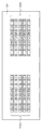
図3は、撮影画面における測距点の配置を示す図であり、本第1の実施形態では、5行×5列の計25点の測距点が配置されている。図4は、図3に示す測距点を配置する為の、ラインセンサ群102a及び102bのブロック分割について説明する図である。
FIG. 3 is a diagram showing the arrangement of distance measuring points on the shooting screen. In the first embodiment, a total of 25 distance measuring points of 5 rows × 5 columns are arranged. FIG. 4 is a diagram for explaining block division of the
図4(a)は、ラインセンサ群102a及び102bのライン1からライン5をそれぞれ3ブロックに分割した場合の、各ブロックと測距点の位置関係を示す図である。ラインセンサ群102a及び102bは、それぞれブロックBLK1〜15の15ブロックに分割され、各ブロック対の信号から焦点状態を検出することで、図3に示す25点の測距点のうち、15点に対応することができる。この状態を第1分割パターンとする。なお、破線で示した測距点は、ブロックの境界上にあるため、第1分割パターンでは焦点状態を検出することができない。
FIG. 4A is a diagram showing a positional relationship between each block and a distance measuring point when the
そこで、本第1の実施形態では、図4(a)の破線上にある測距点に対応するように、ラインセンサ群102a及び102bを第1分割パターンと異なるブロック分割を行う。図4(b)は、ラインセンサ群102a及び102bのライン1からライン5をそれぞれ4ブロックに分割した場合の、各ブロックと測距点の位置関係を示す図である。外側の2つのブロックについてはブロックの長さが短いため、焦点状態の検出には使用せず、中央付近の2つのブロックのみを用いる。したがって、ラインセンサ群102a及び102bは、それぞれブロックBLK16〜25の10ブロックに分割され、各ブロック対の信号から焦点状態を検出することで、図3に示す25点の測距点のうち、10点に対応することができる。この状態を第2分割パターンとする。
Therefore, in the first embodiment, the
図4(a)の第1分割パターンと、図4(b)の第2分割パターンを合わせることで、図3に示す25点すべての測距点について焦点状態の検出が可能となる。 By combining the first divided pattern shown in FIG. 4A and the second divided pattern shown in FIG. 4B, the focus state can be detected for all the 25 distance measuring points shown in FIG.
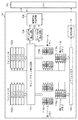
図5は、AFセンサ101の詳細な構成を示すブロック図である。以下、AFセンサ101の各構成の動作について説明する。
FIG. 5 is a block diagram showing a detailed configuration of the
ラインセンサ群102a及び102bは、撮影レンズの異なる射出瞳領域を通過した被写体からの光束をそれぞれ受光し、光電変換により電圧に変換した信号を蓄積する。ライン−ブロック選択回路103は、ラインセンサ群102a及び102bの複数のラインのうち1ラインを選択し、その選択したラインをそれぞれ複数のブロックに分割する。分割パターンは、図4(a)に示す第1分割パターン、もしくは、図4(b)に示す第2分割パターンである。そして、各ブロック対に対応した画素群に蓄積された画素信号(電気信号)を、ボトム信号検出回路104、ピーク信号検出回路105、第1フレームメモリ107a及び107b、第2フレームメモリ108a及び108bへと送信する。
The
ボトム信号検出回路104は、ライン−ブロック選択回路103で選択されたブロック対の画素信号のうち、最小信号(ボトム信号)を検出する。ピーク信号検出回路105は、ライン−ブロック選択回路103で選択されたブロック対の画素信号のうち、最大信号(ピーク信号)を検出する。蓄積停止判定回路106は、検出されたピーク信号とボトム信号に基づいて、そのブロック対の画素信号のレベルが焦点検出に適したレベルにあるかを判断することで蓄積停止タイミングを判定して、ライン−ブロック選択回路103に判定結果を送る。ここでは、例えば、ピーク信号とボトム信号の差が予め設定された値よりも大きい場合や、ボトム信号が共に予め設定された値を超えた場合に、蓄積停止と判断する。
The bottom
ライン−ブロック選択回路103は送られてきた判定結果に基づいて、該当するブロックの蓄積停止する。なお、ここでいう「蓄積停止」は、実際に該当するブロック内の画素における電荷の蓄積を止めるのではなく、第1フレームメモリ107a及び107bまたは第2フレームメモリ108a及び108bに、該当するブロックの画素信号を記憶する動作のことを指す。
The line-
第1フレームメモリ107a及び107bは、それぞれ、ラインセンサ群102a及び102bの信号を記憶する回路であり、第1分割パターンにおけるブロックBLK1〜BLK15に対応した信号を記憶する。
The
第2フレームメモリ108a及び108bは、それぞれ、ラインセンサ群102a及び102bの信号を記憶する回路であり、第2分割パターンにおけるブロックBLK16〜BLK25に対応した信号を記憶する。
The
第1フレームメモリ107a及び107b、第2フレームメモリ108a及び108bに記憶された画素信号は、CPU100がシフトレジスタ回路109を駆動することで、1画素毎に出力回路110を介して出力される。出力回路110は、画素信号を増幅するなどの処理を行い、CPU100のA/D変換器(不図示)へ出力する。
Pixel signals stored in the
以上のように構成された焦点検出装置を有するカメラにおける焦点検出の手順を、図6のフローチャートに基づいて詳細に説明する。 A focus detection procedure in the camera having the focus detection apparatus configured as described above will be described in detail based on the flowchart of FIG.
CPU100は、スイッチ群214の操作により焦点検出の開始信号を受信すると、AFセンサ101を制御することでラインセンサ群102a及び102bにおける信号蓄積動作を開始する(S101)。
When the
S102において、AFセンサ101は、ライン−ブロック選択回路103による選択ブロックを第1分割パターンに設定する。続くS103では、AFセンサ101は、ライン−ブロック選択回路103により選択するブロック番号を「1」に設定する。
In S102, the
そして、ライン−ブロック選択回路103は、設定されたブロック番号のブロック対から得られる画素信号をボトム信号検出回路104とピーク信号検出回路105へ送信する。このボトム信号検出回路104とピーク信号検出回路105から得られるピーク信号とボトム信号から、蓄積停止判定回路106はブロック対毎にその信号レベルが焦点検出に適したレベルにあるかどうかを判断して、蓄積停止判定を行う(S104)。蓄積停止判定回路106により蓄積停止と判定されると、S105へ移行する。一方、蓄積停止と判定されない場合、或いはすでに蓄積停止しているブロック対の場合は、S106へ移行する。
The line-
S105では、ライン−ブロック選択回路103により、S104で蓄積停止と判定されたブロック内の画素信号を第1フレームメモリへ転送する。なお、上述したように、第1フレームメモリ107a及び107bは第1分割パターンにおけるブロック対BLK1〜BLK15のためのメモリである。
In S105, the line-
S106では、AFセンサ101は、現在選択されているブロック番号を1つ進めて再設定する。S107では、AFセンサ101は、設定されているブロック番号が「16」か否かを判定する。ブロック番号が「16」の場合は、第1分割パターンによる蓄積停止判定が、ブロック対BLK1からブロック対BLK15まで一巡しているので、S108の動作へ移行する。
In S106, the
一方、ブロック番号が「16」以外、つまり「2」〜「15」の場合は、第1分割パターンによる蓄積停止判定が一巡してないのでS104動作へ戻って、残りのブロック対について蓄積停止の判定動作を行う。 On the other hand, if the block number is other than “16”, that is, “2” to “15”, the accumulation stop determination by the first division pattern has not been completed, so the process returns to S104 and the remaining blocks are stopped. Performs the judgment operation.
S108では、AFセンサ101は、ライン−ブロック選択回路103による選択ブロックを第2分割パターンに設定する。ライン−ブロック選択回路103は、設定されたブロック番号のブロック対から得られる画素信号をボトム信号検出回路104とピーク信号検出回路105へ送信する。このボトム信号検出回路104とピーク信号検出回路105から得られるピーク信号とボトム信号から、蓄積停止判定回路106はブロック対毎にその信号レベルが焦点検出に適したレベルにあるかどうかを判断して、蓄積停止判定を行う(S110)。蓄積停止判定回路106により蓄積停止と判定されると、S111へ移行する。一方、蓄積停止と判定されない場合、或いはすでに蓄積停止しているブロック対の場合は、S112動作へ移行する。
In S108, the
S111では、ライン−ブロック選択回路103により、S114で蓄積停止と判定されたブロック対から得られた画素信号を第2フレームメモリ108a及び108bへ転送する。なお、上述したように、第2フレームメモリ108a及び108bは第2分割パターンにおけるブロック対BLK16〜BLK25のためのメモリである。
In S111, the line-
S112では、AFセンサ101は、現在選択されているブロック番号を1つ進めて再設定する。S113では、AFセンサ101は、設定されているブロック番号が「26」か、否かを判定する。ブロック番号が「26」の場合は、第2分割パターンによる蓄積停止判定が、ブロック対BLK16からブロック対BLK25まで一巡しているので、S114の動作へ移行する。
In step S112, the
一方、ブロック番号が「26」以外の場合は、第2分割パターンによる蓄積停止判定が一巡してないのでS110動作へ戻って、残りのブロック対について蓄積停止の判定動作を行う。 On the other hand, when the block number is other than “26”, the accumulation stop determination by the second division pattern is not completed, so the process returns to S110 and the accumulation stop determination operation is performed for the remaining block pairs.
S114では、AFセンサ101は、全てのブロック(BLK1〜BLK25)について蓄積停止動作が行われているかを判定する。つまり、ここでは、第1フレームメモリ107a及び107bと第2フレームメモリ108a及び108bへの信号転送が完了しているか否かの判定を行う。
In S114, the
全ブロック対の蓄積停止動作が完了している場合は、CPU100に対して完了信号を送信する。一方、未だ蓄積停止していないブロックがある場合は、S102へ戻り、S114までの動作を繰り返す。このようにして、S101からS114の間に、AFセンサ101内の制御回路によって、信号蓄積動作、蓄積停止判定、信号記憶動作が行われる。
When the accumulation stop operation for all block pairs has been completed, a completion signal is transmitted to the
S115では、AFセンサ101から完了信号を受信したCPU100は、各ブロックの画素信号の読み出し動作を行う。ここでは、CPU100はAFセンサ101を制御して、第1フレームメモリ107a及び107bと第2フレームメモリ108a及び108bに記憶されている画素信号を順次出力させ、CPU100内の不図示のA/D変換器で画素信号をA/D変換していく。A/D変換された画素信号は、記憶回路209に記憶する。
In S115, the
S116では、CPU100は、記憶回路209に記憶した各ブロック対の画素信号に基づいて、位相差検出を行って、それぞれのブロック対に位置する被写体についてデフォーカス量を算出する。
In S116, the
S117では、CPU100は、S116で算出したデフォーカス量に基づいて、レンズ通信回路205を介して不図示の撮影レンズのフォーカスレンズの駆動制御を行い、一連の焦点検出動作を終了する。
In S117, based on the defocus amount calculated in S116, the
上記の通り本第1の実施形態によれば、第1分割パターンと第2分割パターンでラインセンサ群102a及び102bをブロック分割することで、各測距点に対応したラインセンサのブロックを長くとりながら、測距点を多くすることができる。さらに、第1分割パターンと第2分割パターンのそれぞれに対応したフレームメモリを備えることで、一度の信号蓄積動作で両方の分割パターンの信号を得ることができるため、焦点検出に係る時間が長くなるのを防ぐことができる。
As described above, according to the first embodiment, the
<第2の実施形態>
次に、本発明の第2の実施形態について説明する。上述した第1の実施形態におけるAFセンサ101は、ラインセンサ群102a及び102bの分割制御をする際、図4(a)に示す第1分割パターンと図4(b)に示す第2分割パターンにより分割していた。本第2の実施形態では、第1及び第2の分割パターンとは別の分割パターンの例について説明する。
<Second Embodiment>
Next, a second embodiment of the present invention will be described. When the
図7は、本第2の実施形態における分割パターンを示す。図7(a)は第3分割パターンを示しており、各ラインセンサを3分割し、両端の2つのブロックからの画素信号のみを焦点検出処理に用いる。また、図7(b)は第4分割パターンを示しており、各ラインセンサを3分割し、中央1つのブロックからの画素信号のみを焦点検出処理に用いる。なお、図7に示すように、第3分割パターンと第4分割パターンは、ブロックの境界が互いに異なっており、矢印で示す一部の画素が重複している。 FIG. 7 shows a division pattern in the second embodiment. FIG. 7A shows a third division pattern. Each line sensor is divided into three, and only pixel signals from two blocks at both ends are used for focus detection processing. FIG. 7B shows a fourth division pattern. Each line sensor is divided into three, and only pixel signals from one central block are used for focus detection processing. As shown in FIG. 7, the third divided pattern and the fourth divided pattern have different block boundaries, and some pixels indicated by arrows overlap.
図8は、第2の実施の形態におけるAFセンサ101の詳細な構成を示すブロック図である。図5と異なる部分は、ライン−ブロック選択回路113と、第1フレームメモリ114a及び114b、第2フレームメモリ115a及び115bである。本第2の実施形態では、第3分割パターンで2ブロック分、第4分割パターンで1ブロック分の画素信号を、それぞれ第1フレームメモリ114a及び114b、第2フレームメモリ115a及び115bに記憶させる点である。それ以外の構成は図5と同様であるので同じ参照番号を付し、説明を省略する。
FIG. 8 is a block diagram illustrating a detailed configuration of the
図9は、本第2の実施形態における焦点検出の手順を示すフローチャートである。なお、図6と同様の処理は適宜説明を省略し、第1の実施形態と異なる処理を詳細に説明する。ステップS215までの処理では、図6のS102で第1分割パターンを設定する代わりに、S202で第3分割パターンを設定し、図6のS108で第2分割パターンを設定する代わりに、S208で第4分割パターンを設定するところが異なる。また、S207ではBLKが11(=2ブロック×5ライン+1)であるかを判定し、S213では、BLKが16(=11+1ブロック×5ライン)であるかを判定する。上記以外の手順は、図6を参照して説明したものと同様である。 FIG. 9 is a flowchart showing a focus detection procedure in the second embodiment. Note that a description of processing similar to that in FIG. 6 is omitted as appropriate, and processing different from that of the first embodiment is described in detail. In the processing up to step S215, instead of setting the first division pattern in S102 of FIG. 6, the third division pattern is set in S202, and instead of setting the second division pattern in S108 of FIG. The difference is that the quadrant pattern is set. In S207, it is determined whether BLK is 11 (= 2 blocks × 5 lines + 1). In S213, it is determined whether BLK is 16 (= 11 + 1 blocks × 5 lines). The other procedures are the same as those described with reference to FIG.
そして、S215で記憶回路209に記憶された全ブロック対の画素信号から、S216において、1ラインセンサ分の連続信号の生成を行う。図10は連続信号の生成方法を説明するための図である。
Then, a continuous signal for one line sensor is generated in S216 from the pixel signals of all the block pairs stored in the
図10(a)は、図8のライン1(A)を第3分割パターンで分割して得られた、第1フレームメモリ114aに記憶されたブロックBLK1、BLK3の信号である。また、図10(b)は同ラインにおける第4分割パターンで分割して得られた、第2フレームメモリ115aに記憶されたブロックBLK2の信号ある。各ブロックの信号は、蓄積時間が異なるため不連続となっている。しかし、ブロックBLK2の画素信号と、ブロックBLK1、BLK3の画素信号は一部重複しているので、重複している画素信号が同一レベルの信号になるような係数を算出する。そして、重複していない画素信号にも同様の係数を適用することでレベル調整を行って、図10(c)のような1ラインセンサ分の連続信号を生成することができる。
FIG. 10A shows signals of the blocks BLK1 and BLK3 stored in the
そして、ブロックBLK1とBLK2の境界を中心とした範囲の信号をBLK16、BLK2とBLK3の境界を中心とした範囲の信号をBLK17として、記憶回路209に記憶する。同様の処理を全てのラインについて行うことで、図4と同じ測距点に対応することができる。
Then, the signal in the range centered on the boundary between the blocks BLK1 and BLK2 is stored in the
S217では、CPU100は、上述したようにして記憶回路209に記憶した各ブロック対の画素信号に基づいて、位相差検出を行って、それぞれのブロック対に位置する被写体についてデフォーカス量を算出する。
In S217, the
S218では、CPU100は、S217で算出したデフォーカス量に基づいて、レンズ通信回路205を介して不図示の撮影レンズのフォーカスレンズの駆動制御を行い、一連の焦点検出動作を終了する。
In S218, based on the defocus amount calculated in S217, the
上記の通り本第2の実施形態によると、第1の実施形態と同様に、各測拠点に対応したラインセンサのブロックを長くとりながら、測距点を多くすることができる。さらに、第1の実施形態と比較して、各ブロック対の画素信号を記憶しておくためのフレームメモリを、容量の少ないフレームメモリで構成できる。したがって、AFセンサのチップ面積が小さくできるので、コストを低減することができる。 As described above, according to the second embodiment, as in the first embodiment, it is possible to increase the number of distance measuring points while taking a long block of line sensors corresponding to each measurement base. Further, as compared with the first embodiment, the frame memory for storing the pixel signals of each block pair can be configured with a frame memory having a small capacity. Therefore, since the chip area of the AF sensor can be reduced, the cost can be reduced.
なお、上述した第1の及び第2の実施形態では、測距点の数が25点、一対のラインセンサ群が、それぞれ5ラインのラインセンサにより構成されている場合を例に挙げて説明した。しかしながら、本発明は測距点やラインセンサの数により限定されるものではなく、ラインセンサの数や、ブロックへの分割の仕方によって、様々な測距点の配置に対応することができる。 In the first and second embodiments described above, the case where the number of distance measuring points is 25 and the pair of line sensor groups are each configured by a line sensor of 5 lines has been described as an example. . However, the present invention is not limited by the number of distance measuring points and the number of line sensors, and can correspond to various distance measuring point arrangements depending on the number of line sensors and the way of division into blocks.
また、ブロックへの分割パターンも、2種類である場合について説明したが、3種類以上にしてもよい。 Moreover, although the case where there are two types of division patterns into blocks has been described, three or more types may be used.
Claims (7)
前記被写体からの一対の光束を光電変換して、電気信号を出力する光電変換手段と、
複数の測距点のいずれかを選択する選択手段と、
前記光電変換手段から電気信号を読み出す際に、複数の異なるパターンで、前記複数の測距点にそれぞれ対応する複数のブロック対に分けて読み出すと共に、前記ブロック対毎に、該ブロック対の電気信号のレベルが焦点検出に適したレベルになると、前記光電変換手段から電気信号を読み出すように制御する制御手段と、
前記ブロック対毎に読み出された電気信号を記憶する、前記複数のパターンにそれぞれ対応した複数のフレームメモリと、
前記複数のフレームメモリに記憶された電気信号の内、前記選択手段により選択された測距点に対応するブロック対の電気信号の位相差に基づいて、前記撮影レンズの焦点状態を検出する焦点検出手段とを有し、
前記制御手段は、各ブロック対の電気信号の最大信号と最小信号との差が予め設定された値よりも大きくなった場合、及び、前記最小信号が予め設定された値よりも大きくなった場合に、前記ブロック対の電気信号のレベルが焦点検出に適したレベルになったと判断することを特徴とする焦点検出装置。 A focus detection device that detects a focus state of the photographing lens based on a phase difference between a pair of light beams from a subject that has passed through different exit pupil regions of the photographing lens,
The photoelectrically converts a pair of light fluxes from a subject, a photoelectric conversion means for outputting an electrical signal,
A selecting means for selecting one of multiple distance measuring point,
When reading an electric signal from said photoelectric conversion means, a plurality of different such Rupa turn, reads in a plurality of blocks pairs corresponding to the plurality of distance measuring points, before each Chivu lock pair, the block Control means for controlling the electrical signal to be read from the photoelectric conversion means when the level of the electrical signal of the pair reaches a level suitable for focus detection;
Storing electrical signals read out in each of the block pairs, a plurality of frame memories respectively corresponding to said plurality of patterns,
Focus detection for detecting the focus state of the photographing lens based on the phase difference of the electrical signal of the block pair corresponding to the distance measuring point selected by the selection means among the electrical signals stored in the plurality of frame memories. Means ,
The control means, when the difference between the maximum signal and the minimum signal of the electrical signal of each block pair is greater than a preset value, and when the minimum signal is greater than a preset value In addition, it is determined that the level of the electrical signal of the block pair has reached a level suitable for focus detection.
前記被写体からの一対の光束を光電変換して、電気信号を出力する光電変換手段と、
複数の測距点のいずれかを選択する選択手段と、
前記光電変換手段から電気信号を読み出す際に、複数の異なるパターンで、前記複数の測距点のいずれかに対応する複数のブロック対に分けて読み出すと共に、前記ブロック対毎に、該ブロック対の電気信号のレベルが焦点検出に適したレベルになると、前記光電変換手段から電気信号を読み出すように制御する制御手段と、
前記ブロック対毎に読み出された電気信号を記憶する、前記複数のパターンにそれぞれ対応した複数のフレームメモリと、
前記複数のフレームメモリに記憶された電気信号の内、前記複数のパターンで前記ブロック対毎に読み出した電気信号から、前記複数のブロック対が対応していない、前記複数の測距点以外の測距点に対応する電気信号の範囲を設定する生成手段と、
前記選択手段により選択された測距点に対応するブロック対または範囲の電気信号の位相差に基づいて、前記撮影レンズの焦点状態を検出する焦点検出手段と
を有することを特徴とする焦点検出装置。 A focus detection device that detects a focus state of the photographing lens based on a phase difference between a pair of light beams from a subject that has passed through different exit pupil regions of the photographing lens,
The photoelectrically converts a pair of light fluxes from a subject, a photoelectric conversion means for outputting an electrical signal,
A selecting means for selecting one of multiple distance measuring point,
When reading an electric signal from said photoelectric conversion means, a plurality of different such Rupa turn, reads in a plurality of blocks pair corresponding to one of said plurality of distance measuring points, before each Chivu lock pair, Control means for controlling the electrical signal to be read from the photoelectric conversion means when the level of the electrical signal of the block pair reaches a level suitable for focus detection;
Storing electrical signals read out in each of the block pairs, a plurality of frame memories respectively corresponding to said plurality of patterns,
Wherein the plurality of frame memories to the stored electrical signals from the previous SL electric signals read for each of the block pairs with the plurality of patterns, before Symbol plurality of block pair is not compatible, the plurality of distance measuring points Generating means for setting a range of an electric signal corresponding to a distance measuring point other than
A focus detection unit that detects a focus state of the photographing lens based on a phase difference between electrical signals of a block pair or a range corresponding to the distance measuring point selected by the selection unit. .
撮像手段により、前記被写体からの一対の光束を光電変換して、電気信号を出力する光電変換工程と、
選択手段により、複数の測距点のいずれかを選択する選択工程と、
制御手段により、前記光電変換手段から電気信号を読み出す際に、複数の異なるパターンで、前記複数の測距点にそれぞれ対応する複数のブロック対に分けて読み出すと共に、前記ブロック対毎に、該ブロック対の電気信号のレベルが焦点検出に適したレベルになると、前記光電変換手段から電気信号を読み出すように制御する制御工程と、
前記ブロック対毎に読み出された電気信号を、前記複数のパターンにそれぞれ対応した複数のフレームメモリに記憶する記憶工程と、
焦点検出手段により、前記複数のフレームメモリに記憶された電気信号の内、前記選択工程で選択された測距点に対応するブロック対の電気信号の位相差に基づいて、前記撮影レンズの焦点状態を検出する焦点検出工程とを有し、
前記制御工程では、各ブロック対の電気信号の最大信号と最小信号との差が予め設定された値よりも大きくなった場合、及び、前記最小信号が予め設定された値よりも大きくなった場合に、前記ブロック対の電気信号のレベルが焦点検出に適したレベルになったと判断することを特徴とする焦点検出方法。 A focus detection method for detecting a focus state of the photographing lens based on a phase difference between a pair of light beams from a subject that has passed through different exit pupil regions of the photographing lens,
The imaging unit, wherein the photoelectrically converting a pair of light fluxes from a subject, a photoelectric conversion step of outputting an electrical signal,
By the selection means, a selection step of selecting one of several distance measuring point,
The control means, when reading the electric signal from said photoelectric conversion means, a plurality of different such Rupa turn, reads in a plurality of blocks pairs corresponding to the plurality of distance measuring points, before Chivu lock pairwise In addition, when the level of the electric signal of the block pair becomes a level suitable for focus detection, a control step of controlling to read out the electric signal from the photoelectric conversion means ,
A storage step of storing electrical signals read out in each of the block pairs, a plurality of frame memories respectively corresponding to said plurality of patterns,
Based on the phase difference of the electrical signal of the block pair corresponding to the ranging point selected in the selection step among the electrical signals stored in the plurality of frame memories by the focus detection means, the focus state of the photographing lens and a focus detection step of detecting a
In the control step, when the difference between the maximum signal and the minimum signal of the electrical signals of each block pair is greater than a preset value, and when the minimum signal is greater than a preset value. In addition, it is determined that the level of the electrical signal of the block pair has reached a level suitable for focus detection.
撮像手段により、前記被写体からの一対の光束をそれぞれ光電変換して、電気信号を出力する光電変換工程と、
選択手段により、複数の測距点のいずれかを選択する選択工程と、
制御手段により、前記光電変換手段から電気信号を読み出す際に、複数の異なるパターンで、前記複数の測距点のいずれかに対応する複数のブロック対に分けて読み出すと共に、前記ブロック対毎に、該ブロック対の電気信号のレベルが焦点検出に適したレベルになると、前記光電変換工程において電気信号を読み出すように制御する制御工程と、
前記ブロック対毎に読み出された電気信号を、前記複数のパターンにそれぞれ対応した複数のフレームメモリに記憶する記憶工程と、
生成手段により、前記複数のフレームメモリに記憶された電気信号の内、前記複数のパターンで前記ブロック対毎に読み出した電気信号から、前記複数のブロック対が対応していない、前記複数の測距点以外の測距点に対応する電気信号の範囲を設定する生成工程と、
焦点検出手段により、前記選択工程で選択された測距点に対応するブロック対または範囲の電気信号の位相差に基づいて、前記撮影レンズの焦点状態を検出する焦点検出工程と
を有することを特徴とする焦点検出方法。 A focus detection method for detecting a focus state of the photographing lens based on a phase difference between a pair of light beams from a subject that has passed through different exit pupil regions of the photographing lens,
The imaging means, a photoelectric conversion step of a pair of light beams, respectively Re its photoelectrically converts and outputs an electric signal from the subject,
By the selection means, a selection step of selecting one of several distance measuring point,
The control means, when reading the electric signal from said photoelectric conversion means, a plurality of different such Rupa turn, reads in a plurality of blocks pair corresponding to one of said plurality of distance measuring points, before Chivu lock For each pair, when the level of the electric signal of the block pair becomes a level suitable for focus detection, a control step for controlling to read out the electric signal in the photoelectric conversion step ;
A storage step of storing electrical signals read out in each of the block pairs, a plurality of frame memories respectively corresponding to said plurality of patterns,
By generating means, among the electric signals stored in the plurality of frame memories, from the electrical signal read for each of the block pairs with previous SL plurality of patterns, before Symbol plurality of block pair is not compatible, the plurality A generation step of setting a range of an electric signal corresponding to a distance measurement point other than the distance measurement point,
A focus detection step of detecting a focus state of the photographic lens based on a phase difference of an electric signal of a block pair or a range corresponding to the distance measuring point selected in the selection step by a focus detection unit. Focus detection method.
Priority Applications (3)
| Application Number | Priority Date | Filing Date | Title |
|---|---|---|---|
| JP2010011373A JP5576664B2 (en) | 2010-01-21 | 2010-01-21 | Focus detection apparatus and method |
| US12/981,714 US8971697B2 (en) | 2010-01-21 | 2010-12-30 | Focus detection apparatus and focus detection method |
| CN201110024991.3A CN102135659B (en) | 2010-01-21 | 2011-01-21 | Focus detection apparatus and focus detection method |
Applications Claiming Priority (1)
| Application Number | Priority Date | Filing Date | Title |
|---|---|---|---|
| JP2010011373A JP5576664B2 (en) | 2010-01-21 | 2010-01-21 | Focus detection apparatus and method |
Publications (3)
| Publication Number | Publication Date |
|---|---|
| JP2011150139A JP2011150139A (en) | 2011-08-04 |
| JP2011150139A5 JP2011150139A5 (en) | 2013-03-07 |
| JP5576664B2 true JP5576664B2 (en) | 2014-08-20 |
Family
ID=44277647
Family Applications (1)
| Application Number | Title | Priority Date | Filing Date |
|---|---|---|---|
| JP2010011373A Expired - Fee Related JP5576664B2 (en) | 2010-01-21 | 2010-01-21 | Focus detection apparatus and method |
Country Status (3)
| Country | Link |
|---|---|
| US (1) | US8971697B2 (en) |
| JP (1) | JP5576664B2 (en) |
| CN (1) | CN102135659B (en) |
Families Citing this family (6)
| Publication number | Priority date | Publication date | Assignee | Title |
|---|---|---|---|---|
| JP6077872B2 (en) * | 2013-02-06 | 2017-02-08 | キヤノン株式会社 | Focus detection apparatus and control method thereof |
| US9654680B2 (en) * | 2013-10-17 | 2017-05-16 | Canon Kabushiki Kaisha | Image capturing apparatus and control method therefor |
| JP6613065B2 (en) * | 2015-07-10 | 2019-11-27 | キヤノン株式会社 | FOCUS DETECTION DEVICE, ITS CONTROL METHOD, AND IMAGING DEVICE |
| JP6806471B2 (en) | 2016-06-16 | 2021-01-06 | キヤノン株式会社 | Focus detection device and method, and imaging device |
| JP6891071B2 (en) | 2017-08-07 | 2021-06-18 | キヤノン株式会社 | Information processing equipment, imaging system, imaging method and program |
| WO2019104508A1 (en) * | 2017-11-29 | 2019-06-06 | 深圳市大疆创新科技有限公司 | Image sensor, chip, image processing device, and related method |
Family Cites Families (4)
| Publication number | Priority date | Publication date | Assignee | Title |
|---|---|---|---|---|
| GB2298331B (en) * | 1995-02-22 | 2000-02-16 | Asahi Optical Co Ltd | Distance measuring apparatus |
| JP2003215442A (en) * | 2002-01-25 | 2003-07-30 | Canon Inc | Multipoint range-finding device |
| JP2006184320A (en) * | 2004-12-24 | 2006-07-13 | Canon Inc | Focus detecting device and focus detecting method |
| JP5121120B2 (en) * | 2005-02-08 | 2013-01-16 | キヤノン株式会社 | Focus detection apparatus and optical instrument |
-
2010
- 2010-01-21 JP JP2010011373A patent/JP5576664B2/en not_active Expired - Fee Related
- 2010-12-30 US US12/981,714 patent/US8971697B2/en not_active Expired - Fee Related
-
2011
- 2011-01-21 CN CN201110024991.3A patent/CN102135659B/en not_active Expired - Fee Related
Also Published As
| Publication number | Publication date |
|---|---|
| US20110176794A1 (en) | 2011-07-21 |
| CN102135659A (en) | 2011-07-27 |
| JP2011150139A (en) | 2011-08-04 |
| CN102135659B (en) | 2014-11-05 |
| US8971697B2 (en) | 2015-03-03 |
Similar Documents
| Publication | Publication Date | Title |
|---|---|---|
| JP6317548B2 (en) | Imaging apparatus and control method thereof | |
| EP2809063B1 (en) | Image capturing apparatus and image processing method | |
| JP5576664B2 (en) | Focus detection apparatus and method | |
| US8922703B2 (en) | Focus detection apparatus | |
| JP5789098B2 (en) | Focus detection apparatus and control method thereof | |
| JP2007189312A (en) | Imaging apparatus, imaging method, and camera | |
| JP6504969B2 (en) | Imaging system, imaging apparatus, lens apparatus, control method of imaging system | |
| JP2014153509A (en) | Imaging device and imaging method | |
| CN109639953B (en) | Focus detection control device and imaging device | |
| JP2013218297A (en) | Focus adjustment device and focus adjustment method | |
| JP5361598B2 (en) | Focus adjustment apparatus and method, and imaging apparatus | |
| JP2011150139A5 (en) | ||
| JP4642547B2 (en) | Focus detection device | |
| JP6512989B2 (en) | Focus detection apparatus and method, and imaging apparatus | |
| US20180007295A1 (en) | Focus adjustment device and focus adjustment method | |
| JP6530610B2 (en) | Focusing device, imaging device, control method of focusing device, and program | |
| JP6803941B2 (en) | Imaging system, imaging device, lens device, control method of imaging system | |
| JP6902921B2 (en) | Imaging equipment, control methods, and programs | |
| JP7207874B2 (en) | CONTROL DEVICE, IMAGING DEVICE, CONTROL METHOD, PROGRAM, AND STORAGE MEDIUM | |
| JP5478751B2 (en) | Photoelectric conversion element | |
| JP5226573B2 (en) | Photoelectric conversion element | |
| JP2005148229A (en) | Photoelectric convertor and automatic focus detector | |
| JP6765829B2 (en) | Image processing device, control method of image processing device, imaging device | |
| JP6530609B2 (en) | Focusing device, imaging device, control method of focusing device, and program | |
| JP2023114698A (en) | Imaging apparatus, method for controlling imaging apparatus, and program |
Legal Events
| Date | Code | Title | Description |
|---|---|---|---|
| A521 | Request for written amendment filed |
Free format text: JAPANESE INTERMEDIATE CODE: A523 Effective date: 20130121 |
|
| A621 | Written request for application examination |
Free format text: JAPANESE INTERMEDIATE CODE: A621 Effective date: 20130121 |
|
| A977 | Report on retrieval |
Free format text: JAPANESE INTERMEDIATE CODE: A971007 Effective date: 20131219 |
|
| A131 | Notification of reasons for refusal |
Free format text: JAPANESE INTERMEDIATE CODE: A131 Effective date: 20140106 |
|
| A521 | Request for written amendment filed |
Free format text: JAPANESE INTERMEDIATE CODE: A523 Effective date: 20140307 |
|
| TRDD | Decision of grant or rejection written | ||
| A01 | Written decision to grant a patent or to grant a registration (utility model) |
Free format text: JAPANESE INTERMEDIATE CODE: A01 Effective date: 20140606 |
|
| A61 | First payment of annual fees (during grant procedure) |
Free format text: JAPANESE INTERMEDIATE CODE: A61 Effective date: 20140704 |
|
| R151 | Written notification of patent or utility model registration |
Ref document number: 5576664 Country of ref document: JP Free format text: JAPANESE INTERMEDIATE CODE: R151 |
|
| LAPS | Cancellation because of no payment of annual fees |