JP5574719B2 - Display device, display method, and program - Google Patents
Display device, display method, and program Download PDFInfo
- Publication number
- JP5574719B2 JP5574719B2 JP2010007066A JP2010007066A JP5574719B2 JP 5574719 B2 JP5574719 B2 JP 5574719B2 JP 2010007066 A JP2010007066 A JP 2010007066A JP 2010007066 A JP2010007066 A JP 2010007066A JP 5574719 B2 JP5574719 B2 JP 5574719B2
- Authority
- JP
- Japan
- Prior art keywords
- recorded
- recorded video
- time
- display
- specified time
- Prior art date
- Legal status (The legal status is an assumption and is not a legal conclusion. Google has not performed a legal analysis and makes no representation as to the accuracy of the status listed.)
- Active
Links
Images


Description
本発明は、表示装置、表示方法及びプログラムに関する。 The present invention relates to a display device, a display method, and a program.
従来、録画の再生方法では、映像の特徴的な場面に対してイベントを生成し、利用者にイベントを選択させることでその場面の映像を再生する方法が一般的であった(特許文献1)。また、予めイベントに関連する複数のカメラを設定しておくことで、利用者がイベントを選択することにより複数のカメラの映像を再生する方法が一般的であった(特許文献2)。 Conventionally, in a recording reproduction method, an event is generated for a characteristic scene of a video, and a video of the scene is reproduced by allowing a user to select an event (Patent Document 1). . In addition, a method of reproducing images from a plurality of cameras when a user selects an event by setting a plurality of cameras related to the event in advance (Patent Document 2).
しかしながら、利用者がイベントを選択する方法の場合、異なる複数のイベントが同じ時間帯に重なっていると、利用者がイベントの場面の録画(映像)を確認する必要があった。 However, in the case where the user selects an event, if a plurality of different events overlap in the same time zone, the user needs to check the recording (video) of the event scene.
本発明はこのような問題点に鑑みなされたもので、表示条件に合わせて録画映像を選択、配置することを目的とする。 The present invention has been made in view of such a problem, and an object thereof is to select and arrange a recorded video in accordance with display conditions.
そこで、本発明の表示装置は、複数のネットワークカメラで撮影され、録画された録画映像を表示する表示装置であって、録画された録画映像を取得する取得手段と、指定時刻に録画された録画映像の解析結果又は指定時刻における外部センサーの検知結果と表示条件とを比較し、比較結果によってネットワークカメラを選択する選択手段と、指定時刻から再生する時刻の範囲における前記録画された録画映像の解析結果又は指定時刻から再生する時刻の範囲における前記外部センサーの検知結果が表示条件を満たす期間の長さに基づいて、前記選択手段により選択されたネットワークカメラにより指定時刻に録画された録画映像を表示するレイアウトを決定する決定手段と、を有する。 Therefore, the display device of the present invention, taken at a plurality of network cameras, a display device for displaying the recorded recorded video obtaining means for obtaining the recorded recorded video was recorded at a specified time recording comparing the detection result and Viewing conditions external sensor in the analysis result or the specified time of the video, comparing and selecting means for selecting a network camera by the results, the recorded recordings in the range of time to be reproduced from the designated time The recorded video recorded at the specified time by the network camera selected by the selection means based on the analysis result or the length of the period in which the detection result of the external sensor in the range of the playback time from the specified time satisfies the display condition Determining means for determining a layout to be displayed.
本発明によれば、表示条件に合わせて録画映像を選択、配置することができる。 According to the present invention, recorded video can be selected and arranged according to display conditions.
以下、本発明の実施形態について図面に基づいて説明する。 Hereinafter, embodiments of the present invention will be described with reference to the drawings.
<実施形態1>
図1は、映像記録再生システムのシステム構成の一例を示す図である。映像記録再生システム、映像をネットワークに配信する少なくとも1つ以上のネットワークカメラ(ネットワークカメラ102、103、104)と、ネットワークカメラからの映像を録画する録画装置105と、を含む。また、映像記録再生システムは、ネットワークカメラからの映像又は録画装置105からの映像を表示する表示装置106を含む。ネットワークカメラは、図1に示すように複数台であってもよいし、1台であってもよい。また、録画装置105は、図1に示すように1台であってもよいし、複数台であってもよい。また、表示装置106も、図1に示すように1台であってもよいし、複数台あってもよい。また、ネットワークカメラは、時系列な電子データを生成する装置であり、映像以外の音声データや温度計等のセンサーの時系列なデータを送信する装置であってもよい。
<
FIG. 1 is a diagram illustrating an example of a system configuration of a video recording / playback system. The video recording / playback system includes at least one or more network cameras (
図2は、ネットワークカメラのハードウェア構成の一例を示す図である。201は、カメラ等の撮像部である。202は、撮像部201を載せることができる雲台等の駆動部である。203は、撮像部201や駆動部202を制御する制御部である。204は、CPU等の演算処理を行う処理部である。205は、メモリ等のデータを記憶する記憶部である。206は、外部の装置とネットワークを介して通信をする通信部である。207は、ネットワークカメラに人感センサーやドアセンサー等の機器を接続するための外部センサー部である。撮像部201は、映像を撮影するだけではなく、撮影を行う際のズーム倍率やフォーカスや絞りやシャッタースピードやゲインや赤外線撮影等といった撮影設定を変更する。駆動部202は、雲台を移動することで、雲台に載せた撮像部201の撮影方向や撮影姿勢を変更する。制御部203は、撮像部201の撮影設定や駆動部202の撮影方向や撮影姿勢を制御する。通信部206が表示装置106や録画装置105からネットワークカメラを操作するコマンドを受信した場合、処理部204にてコマンドを解析し、解析結果に基づいて制御部203から撮像部201の撮影設定や、駆動部202の撮影方向等を制御する。
撮像部201で撮影した映像を、通信部206から表示装置106や録画装置105に送信する。また、撮像部201で撮影した映像を記憶部205で一時保存し、映像に撮像部201の撮影設定の情報や駆動部202の撮影姿勢の情報等を追加し、通信部206から送信する。記憶部205は、映像解析のプログラム又はアルゴリズムとその設定を保存しており、また外部センサーを解析するプログラム又はアルゴリズムとその設定を保存している。処理部204は、記憶部205に保存している映像解析のプログラム又はアルゴリズムとその設定を読み込み、記憶部205に一時保存した映像に対して映像解析を実施して結果を通信部206より送信する。また、処理部204は、記憶部205に保存している外部センサー解析のプログラム又はアルゴリズムとその設定を読み込み、外部センサー部207の入力を解析して結果を通信部206より送信する。
FIG. 2 is a diagram illustrating an example of a hardware configuration of the network camera.
The video captured by the
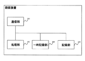
図3は、録画装置のハードウェア構成の一例を示す図である。301は、他の装置と通信を行う通信部である。302は、録画装置全体の制御と演算処理を行うCentral Processing Unit(CPU)等の処理部である。303は、プログラムやデータを一時記憶するRandom Access Memory(RAM)等一時記憶部である。304は、ハードディスクや光ディスクやメモリカード等のデータを記録する記録部である。録画装置105は、複数のネットワークカメラから受信したそれぞれの映像を記録部304に保存する。また、録画装置105は、複数のネットワークカメラから受信したそれぞれの映像解析結果や外部センサー結果を記録部304に保存する。記録部304は、映像解析のプログラム又はアルゴリズムとその設定を保存している。ネットワークカメラから受信した映像を一時記憶部303に保存し、処理部302で映像解析のプログラム又はアルゴリズムとその設定を読み込み、一時保存した映像に対して映像解析を実施して結果を記録部304に保存する。
通信部301が表示装置106から記録している映像の再生コマンドを受信した場合は、処理部302にてコマンドを解析し、再生する映像の撮影元のネットワークカメラと撮影時刻と再生方法とを特定する。そして、処理部302が、記録部304に該当する映像があるかを確認し、該当する映像がある場合には通信部301よりコマンドの送信元の表示装置に映像を送信する。記録部304では、ネットワークカメラ毎に設置位置や用途等の利用者が定めたメタ情報を保存することができる。
FIG. 3 is a diagram illustrating an example of a hardware configuration of the recording apparatus.
When the
図4は、表示装置のハードウェア構成の一例を示す図である。404は、表示装置106の全体を制御すると共に演算処理を行うCentral Processing Unit(CPU)等の処理部である。401は、他装置との通信を行う通信部である。402は、プログラムやデータを一時記憶するRandom Access Memory(RAM)等一時記憶部である。403は、データの表示を制御するモニタやディスプレイ等とのインターフェース部分である表示部である。405は、データを入力するポインティングデバイスやキーボード等の入力デバイスとのインターフェースである。利用者が入力I/F405の操作により録画を再生するネットワークカメラと再生時刻とを指定した場合、処理部404で再生コマンドを生成し、通信部401より録画装置105に送信する。再生コマンドの結果として映像データを受信した場合、処理部404で映像データを復号化して表示部403に表示する。
FIG. 4 is a diagram illustrating an example of a hardware configuration of the display device.
表示装置106における録画再生における映像配置位置の処理について、図5から図8までを用いて説明する。図5は、表示装置の処理部で実行する、録画再生の処理の一例を示すフローチャートである。図6は、表示装置の処理部で実行する、複数のネットワークカメラから録画の再生の表示条件に合致するネットワークカメラを選定し、ネットワークカメラデータの一例である表示リストを作成する処理を示すフローチャートである。図7は、レイアウト情報及びレイアウト情報のデータ構成の一例を示す図である。図8は、表示装置の処理部で実行する表示リストからレイアウトへの配置を算出する処理の一例を示すフローチャートである。
図5のフローチャートについて説明する。処理部404は、ユーザーからの操作や他装置からのコマンドにより、録画再生の処理を開始する。録画再生の再生時刻は、ユーザーにより操作や他装置からのコマンド等により指定される。再生時刻の範囲は、事前に既定された範囲や再生時刻から処理部404によって算出される期間である。処理部404は、再生時刻と再生時刻の範囲とを取得、又は算出して読み込む(S501)。次に、処理部404は、再生の表示条件と各ネットワークカメラの再生時刻での状態とから、再生を表示するネットワークカメラを選定して表示リストを生成する(S502)。S502の処理の詳細は、後述する図6を用いて説明する。次に、処理部404は、表示リストとレイアウト情報と配置条件とから各映像の表示位置や大きさを決定する(S503)。S503の処理の詳細は、後述する図8を用いて説明する。次に、処理部404は、録画装置105から取得した指定時刻の映像をS503の処理結果に基づいて表示する(S504)。次に、処理部404は、録画の再生を継続するかを判断し、継続すると判断した場合は、S506の処理を行い、S502からの処理を繰り返す(S505)。S506では、処理部404は、再生操作(再生、逆再生、早送り、巻き戻し等)の状態から再生時刻を更新し、また再生時刻の範囲が再生時刻を基準としている場合には再生時刻の範囲を更新する。
The processing of the video arrangement position in the recording / playback on the
The flowchart of FIG. 5 will be described. The
表示条件として例えば5つの条件が記録されている。なお、表示条件は、例えば、一時記憶部402等に記憶されている。表示条件としては、例えば、
クエリー1 ドアセンサー:on
クエリー2 動き検知:on
クエリー3 "ドアセンサー:on"and"動き検知:on"
クエリー4 "ドアセンサー:on"or"動き検知:on"
クエリー5 "「カメラ設置情報」に「階段」を含む"andドアセンサー:on
等がある。
表示装置106で録画の再生をする場合にはユーザーからの操作や他装置からのコマンド等により使用する条件が指定される。条件の一つであるクエリー1は、ネットワークカメラ102〜104の何れかの外部センサー部207にドアの開閉を検知するセンサーを接続し、その開閉をイベントといて録画装置105に記録している場合の条件である。より具体的に説明すると、ドアセンサーがon(例えば、ドアが開いている)を通知した期間の映像を、表示するという条件である。クエリー2は、ネットワークカメラ102〜104若しくは録画装置105にて映像を解析して映像の中の動きを検知し、その動きの有無をイベントとして録画装置105に記録している場合の条件である。より具体的に説明すると、動きがon(例えば、映像に動きがある)を通知した期間の映像を、表示するという条件である。クエリー3は、先ほどのドアセンサーと動きとの両方を録画装置105に記録している場合に、ドアセンサーがonであり、かつ、動きがonの期間の映像を、表示するという条件である。クエリー4は、ドアセンサーがonである若しくは動きがonである期間の映像を、表示するという条件である。クエリー5は、ネットワークカメラ毎にその設置場所や用途等を表すメタ情報であるカメラ設置情報を、ネットワークカメラ内の記憶部205若しくは録画装置105の記録部304に記録している場合の条件である。より具体的に説明すると、カメラ設置情報のなかに「階段」の文字列を含むネットワークカメラの映像で、かつ、ドアセンサーがonの期間の映像を、表示するという条件である。
For example, five conditions are recorded as display conditions. The display conditions are stored, for example, in the
Etc.
When recording is reproduced on the
図6の表示リストの算出のフローチャートについて説明する。
既に録画の再生を行っており、現在はその再生の継続であり、処理部404は、表示条件が1つ前の再生の表示から使用する表示条件が変更されているかを判断する(S701)。
使用する表示条件が継続の場合(S701/No)、処理部404は、1つ前の再生表示の処理で算出した表示リストの内容をコピーして表示リストの元とし、Updateフラグ変数にTrueの値を代入する(S702)。使用する表示条件が継続でない場合(S701/Yes)、処理部404は、新規に表示リストを作成し、Updateフラグ変数にFalseの値を代入する(S703)。処理部404は、録画装置105で録画をしている全てのネットワークカメラについて順次選択し、続く処理を行う。処理部404は、選択したネットワークカメラについて、再生時刻についてのネットワークカメラの周辺の状態を録画装置105に要求して取得する(S704)。ここで、周辺とは、例えば、ネットワークカメラから予め定められた範囲内をいうものとする。処理部404は、Updateフラグ変数がTrueであるかを判断する(S705)。Updateフラグ変数がTrueの場合(S705/Yes)、処理部404は、選択したネットワークカメラについて1つ前の再生時刻の状態を録画装置105に要求して取得する若しくは表示装置106で前の処理で使用した状態のキャッシュから取得する。そして、処理部404は、前記取得した状態とS704で取得した状態とに差があるか否かを、状態を比較して判断する(S706)。1つ前の再生時刻の状態と再生時刻の状態とに差がある場合(S706/Yes)とUpdateフラグ変数がFalseの場合(S705/No)、処理部404は、S704で取得した状態が表示条件を満たすか否かを比較して判断する(S707)。表示条件を満たす場合(S707/Yes)、処理部404は、表示リストに選択したネットワークカメラを追加する(S708)。表示条件を満たさない場合(S707/No)、処理部404は、表示リストに選択したネットワークカメラがある場合には削除する(S709)。処理部404は、録画装置105で録画している全てのネットワークカメラについて選択し処理を行ったかを判断する(S710)。未処理のネットワークカメラがある場合(S710/No)、処理部404は、S704より処理を繰り返す。
The display list calculation flowchart of FIG. 6 will be described.
The recording has already been played back, and the playback is now continuing, and the
When the display condition to be used is continuation (S701 / No), the
図7の(A)は、複数の映像を同時に表示する場合に、表示装置106からモニタやディスプレイに表示する領域の分け方であるレイアウトの一例を示している。801は表示の全領域であり、802〜807はそれぞれ映像の表示領域を示している。
図7の(B)は、表示装置106の一時記憶部402、又は録画装置105の記録部304等に記録されている図7で示したレイアウト情報のデータ構成を示している。レイアウト情報は、後述の映像配置を算出する際に使用される各領域の優先度と、領域の左上の座標である基点と、領域のサイズと、からなる。
FIG. 7A shows an example of a layout that is a method of dividing an area to be displayed on the monitor or display from the
7B shows the data structure of the layout information shown in FIG. 7 recorded in the
図8は、図6のフローチャートで算出した表示リストと図7のレイアウト情報とから、レイアウト上へ映像(画像)を配置するための処理の一例を示したフローチャートである。処理部404は、S502(図6のフローチャート)で算出した表示リストに登録されているネットワークカメラを順次選択して処理をする(S1001)。次に、処理部404は、選択したネットワークカメラについて、S501で指定した又はS506で更新をした再生時刻の範囲の状態を録画装置105にリクエストして取得する。処理部404は、表示装置106にキャッシュされた過去のリクエスト結果から算出してもよいし、キャッシュの不足部分だけリクエストして取得してもよい(S1002)。次に、処理部404は、S1002で取得した再生時刻の範囲の状態から、配置条件と合致する期間を算出し記憶する(S1003)。処理部404は、表示リストのネットワークカメラについて全て処理したかを判断する(S1004)。未処理のネットワークカメラがある場合(S1004/No)、処理部404は、S1001から処理を繰り返す。次に、処理部404は、表示リストのネットワークカメラを、S1003で算出した値に基づき、配置条件で示した順(例えば、昇順又は降順)に並び替える(S1005)。次に、処理部404は、S1005で並び替えた表示リストからネットワークカメラを順次選択し、並び替えた順と該当するレイアウト情報の優先順位の表示領域に選択したネットワークカメラを割り当てる(S1006)。次に、処理部404は、表示リストのネットワークカメラについて全て処理したかを判断する(S1007)。未処理のネットワークカメラがある場合(S1007/No)、処理部404は、S1006からの処理を繰り返す。
FIG. 8 is a flowchart showing an example of processing for arranging a video (image) on the layout from the display list calculated in the flowchart of FIG. 6 and the layout information of FIG. The
図9は、録画装置105の記録している状態(状態情報)の一例を模式的に示している。録画装置105は、カメラ1とカメラ2とカメラ3の3台のネットワークカメラからの映像を記録している。また、カメラ1とカメラ2とのネットワークカメラの外部センサー部にそれぞれドアセンサーを接続しており、ドアセンサーの状態を録画装置105に記録している。カメラ1とカメラ3とのネットワークカメラの映像については、ネットワークカメラ内部若しくは録画装置において映像解析を行い、映像から動きを検出しており動きの状態を録画装置105に記録している。カメラ1については、1101が録画の期間、1102と1103とがドアセンサーが検知した期間、1104と1105とが動きを検知した期間を示している。カメラ2については、1106と1107とが録画の期間、1108と1109とがドアセンサーが検知した期間を示している。カメラ3については、1110が録画の期間、1111が動きを検知した期間を示している。
図9の記録の状態において表示条件をクエリー1の「ドアセンサー:on」、再生時刻の範囲を「再生時刻から17:00まで」、配置条件を「再生時刻の範囲でドアセンサーがonの期間が長い順」、図7のレイアウト情報の条件で再生した場合の結果を例に説明する。再生時刻がT0からT1までの期間は表示する映像はない。再生時刻がT1からT2までの期間は、処理部404は、カメラ1の録画を図7の802の領域に表示する。再生時刻がT2からT5までの期間は、処理部404は、カメラ1の録画を802の領域に、カメラ2の録画を803の領域に表示する。再生時刻がT5からT6までの期間は表示する映像はない。再生時刻がT6からT7までの期間は、処理部404は、カメラ1の録画を図7の802の領域に表示する。再生時刻がT7からT9までの期間は、処理部404は、カメラ2の録画を802の領域に、カメラ1の録画を803の領域に表示する。再生時刻がT9からT11までの期間は、処理部404は、カメラ2の録画を802の領域に表示する。
なお、処理部404は、図5のS502において、表示リストに表示するネットワークカメラが1つもない場合には、再生時刻と範囲とを更新して、再度、S502の処理を実行してもよい。この処理を実施した場合、図9の例においてはT0からT1までの間の再生時刻になった場合、再生時刻はT1に移動する。T5からT6までの場合、再生時刻はT6に移動する。
FIG. 9 schematically illustrates an example of a state (state information) recorded by the
In the recording state of FIG. 9, the display condition is “door sensor: on” of
If there is no network camera to be displayed in the display list in S502 of FIG. 5, the
<実施形態2>
以下、実施形態2について説明する。上述した実施形態1との相違点を主に説明し、実施形態1との共通点については説明を省略、或いは簡略化する。図10は、表示装置の表示の一例を示す図である。1201の領域は、映像表示の領域であり図7で説明したレイアウトで構成される。1202で領域は、再生時刻の操作コントロールである。1203は、再生時刻の範囲を示している。1204は、再生時刻を示している。利用者がマウスやタッチパネル等の入力インターフェースより操作して、1204のアイコン移動することで再生時刻の変更を指示することができる。また、利用者は、1203の領域を移動することで再生時刻の範囲の変更を指示することができる。また、利用者は、1202の領域内で2点を指定する、又はドラッグ操作等により領域を指定することで再生時刻の範囲を指定することができる。
<
The second embodiment will be described below. Differences from the above-described first embodiment will be mainly described, and description of common points with the first embodiment will be omitted or simplified. FIG. 10 is a diagram illustrating an example of display on the display device. An
<実施形態3>
実施形態3について説明する。上述した実施形態1との相違点を主に説明し、実施形態1との共通点については説明を省略、或いは簡略化する。図8のS1003の配置条件で比較する値の算出方法の一例について図11のフローチャートを用いて説明する。処理部404は、変数tに再生時刻の範囲の開始時刻を代入し、dに再生方向の録画の単位時間間隔を代入し、表示条件合致回数の変数cと表示条件合致の継続期間の変数Tcと表示条件合致の総期間の変数Tsumとを初期化する(S1301)。次に、処理部404は、変数S1に時刻tで表示条件を満たしているかの結果(True又はFalse)を代入し、変数S2に時刻t+dで表示条件を満たしているかの結果を代入する(S1302)。次に、処理部404は、S1とS2とが共にTrueかを判断する(S1303)。次に、S1とS2とが共にTrueの場合(S1303/Yes)、処理部404は、Tsumに現在のTsumとdとの絶対値の和を代入する(S1305)。次に、処理部404は、cの値が0かを判断する(S1306)。0の場合(S1308/Yes)、処理部404は、cに1を代入する。0でない場合(S1308/No)、処理部404は、cの値が1かを判断する(S1307)。1の場合(S1307/Yes)、又はS1308に続いて、処理部404は、TcにTcの現在値とdの絶対値との和を代入する(S1309)。一方、S1とS2とが共にTrueでない場合(S1303/No)、処理部404は、S2がTrueであるかを判断する(S1304)。S2がTrueの場合(S1304/Yes)、処理部404は、cの値を1つ増やす(S1310)。処理部404は、時刻tに現在のtとdの和を代入する(S1311)。次に、処理部404は、時刻tが再生時刻の範囲外になったかを判断する(S1312)。範囲内の場合、処理部404は、S1302からの処理を繰り返す。
<
A third embodiment will be described. Differences from the above-described first embodiment will be mainly described, and description of common points with the first embodiment will be omitted or simplified. An example of a method for calculating a value to be compared under the arrangement condition in S1003 in FIG. 8 will be described using the flowchart in FIG. The
図11のフローチャートにより、再生時刻の範囲内で表示条件への最初の合致が継続する期間、表示条件を合致する回数、表示条件に合致する総期間を算出することができる。ここで、
エリア1 再生時刻から再生方向に一定期間
エリア2 再生時刻から生成方向とは逆に一定期間
エリア3 再生時刻を中心に一定期間
エリア4 再生時刻に関係ない一定期間
は、再生時刻の範囲の決定方法の一例であり、4つの種類がある。エリア1は、再生時刻から再生方向に一定期間。エリア2は、再生時刻から再生方向とは逆に一定期間。エリア3は再生時刻を中心に一定期間。エリア4は、再生時刻とは関係なく一定の期間。図11のフローチャートの算出結果と、この範囲種類と、図8のS1005のソート方向と、再生の方向と、の4つを組み合わせることで、処理部404は、配置の優先順位のつけ方を設定する。処理部404は、再生時刻の範囲をエリア2、再生方向を逆で、表示条件への最初の合致が継続する期間Tcを算出し、Tcを降順にソートすることで表示条件をより早い時刻に満たしたネットワークカメラにより高い優先度をつけることができる。また、処理部404は、再生時刻の範囲をエリア1、再生方向で、表示条件と合致する総期間Tsumを算出し、Tsumを降順にソートすることで、再生方向で表示条件を満たす割合が高い順に優先度をつけることができる。また、処理部404は、再生時刻の範囲をエリア1、再生方向で、表示条件への最初の合致が継続する期間Tcを算出し、Tcを降順にソートすることで表示条件を満たす期間が長い順に優先度をつけることができる。
With the flowchart in FIG. 11, it is possible to calculate the period during which the first match with the display condition continues within the range of the reproduction time, the number of times that the display condition is met, and the total period that matches the display condition. here,
Area 1 A fixed period from playback time to playback direction Area 2 A fixed period from playback time to generation direction Area 3 A fixed period centered on playback time Area 4 A fixed period not related to playback time is a method for determining the range of playback time There are four types.
図8のS1003において、処理部404は、再生時刻における映像のフレームレートや画像解像度や視野角度等の値、又はそれら値の組み合わせを、配置条件で比較する値としてもよい。また、処理部404は、映像解析の結果(例えば、認識した顔の数、動きを検知した領域面積等)を、配置条件で比較する値としてもよい。また、処理部404は、表示条件を満たした複数のネットワークカメラの中で、各ネットワークカメラに設定されたメタ情報を比較して、共通するメタ情報を多く持つ順を配置条件で比較する値としてもよい。
また、図8のS1006において、処理部404は、現在表示中のレイアウトへの割り当てと比較して、同じネットワークカメラの割り当てを行う場合は現在の割り当て位置から変更しなくてもよい。
In S1003 in FIG. 8, the
Further, in S1006 of FIG. 8, the
<その他の実施形態>
また、本発明は、以下の処理を実行することによっても実現される。即ち、上述した実施形態の機能を実現するソフトウェア(プログラム)を、ネットワーク又は各種記憶媒体を介してシステム或いは装置に供給し、そのシステム或いは装置のコンピュータ(又はCPUやMPU等)がプログラムを読み出して実行する処理である。
<Other embodiments>
The present invention can also be realized by executing the following processing. That is, software (program) that realizes the functions of the above-described embodiments is supplied to a system or apparatus via a network or various storage media, and a computer (or CPU, MPU, etc.) of the system or apparatus reads the program. It is a process to be executed.
以上、上述した各実施形態によれば、利用者による再生時刻の指定に基づき、自動的に録画を選択、配置することができる。 As described above, according to each of the above-described embodiments, recording can be automatically selected and arranged based on designation of a reproduction time by a user.
以上、本発明の好ましい実施形態について詳述したが、本発明は係る特定の実施形態に限定されるものではなく、特許請求の範囲に記載された本発明の要旨の範囲内において、種々の変形・変更が可能である。 The preferred embodiments of the present invention have been described in detail above, but the present invention is not limited to such specific embodiments, and various modifications can be made within the scope of the gist of the present invention described in the claims.・ Change is possible.
404 処理部 404 processor
Claims (8)
録画された録画映像を取得する取得手段と、
指定時刻に録画された録画映像の解析結果又は指定時刻における外部センサーの検知結果と表示条件とを比較し、比較結果によってネットワークカメラを選択する選択手段と、
指定時刻から再生する時刻の範囲における前記録画された録画映像の解析結果又は指定時刻から再生する時刻の範囲における前記外部センサーの検知結果が表示条件を満たす期間の長さに基づいて、前記選択手段により選択されたネットワークカメラにより指定時刻に録画された録画映像を表示するレイアウトを決定する決定手段と、
を有する表示装置。 A display device that displays recorded video shot and recorded by a plurality of network cameras,
An acquisition means for acquiring a recorded video image;
Comparing the detection result and Viewing conditions external sensor in the analysis result or the specified time of recorded recordings at a specified time, and selecting means for selecting a network camera according to the comparison result,
The selection means based on the length of a period in which the analysis result of the recorded video recorded in the time range to be reproduced from the designated time or the detection result of the external sensor in the time range to be reproduced from the designated time satisfies the display condition Determining means for determining a layout for displaying a recorded video recorded at a specified time by the network camera selected by
A display device.
前記決定手段は、前記指定手段により指定された指定時刻から再生する時刻の範囲における前記録画された録画映像の解析結果又は前記指定手段により指定された指定時刻から再生する時刻の範囲における前記外部センサーの検知結果が表示条件を満たす期間の長さに基づいて、前記選択手段により選択されたネットワークカメラにより指定時刻に録画された録画映像を表示するレイアウトを決定する請求項1記載の表示装置。 Further comprising designation means for designating a time range to be reproduced from the designated time;
The determination means includes the analysis result of the recorded video recorded in the time range to be reproduced from the designated time designated by the designation means or the external sensor in the time range to be reproduced from the designated time designated by the designation means. The display device according to claim 1, wherein a layout for displaying a recorded video recorded at a specified time by the network camera selected by the selection unit is determined based on a length of a period in which the detection result satisfies a display condition .
録画された録画映像を取得する取得手段と、
指定時刻に録画された録画映像の解析結果と表示条件とを比較し、比較結果によってネットワークカメラを選択する選択手段と、
指定時刻から再生する時刻の範囲における前記録画された録画映像の解析結果が表示条件を満たす期間の長さに基づいて、前記選択手段により選択されたネットワークカメラにより指定時刻に録画された録画映像を表示するレイアウトを決定する決定手段と、
を有する表示装置。 A display device that displays recorded video shot and recorded by a plurality of network cameras,
An acquisition means for acquiring a recorded video image;
A selection means for comparing an analysis result of a recorded video recorded at a specified time with a display condition, and selecting a network camera according to the comparison result;
The recorded video recorded at the specified time by the network camera selected by the selection means based on the length of the period during which the analysis result of the recorded recorded video in the time range to be played from the specified time satisfies the display condition A determining means for determining a layout to be displayed;
A display device.
指定時刻に録画された録画映像の解析結果又は指定時刻における外部センサーの検知結果と表示条件とを比較し、比較結果によってネットワークカメラを選択する選択ステップと、
指定時刻から再生する時刻の範囲における前記録画された録画映像の解析結果又は指定時刻から再生する時刻の範囲における前記外部センサーの検知結果が表示条件を満たす期間の長さに基づいて、前記選択ステップにより選択されたネットワークカメラにより指定時刻に録画された録画映像を表示するレイアウトを決定する決定ステップと、
を含む表示方法。 A display method executed by a display device that displays recorded video shot and recorded by a plurality of network cameras,
A selection step of comparing the display result with the analysis result of the recorded video recorded at the specified time or the detection result of the external sensor at the specified time, and selecting the network camera according to the comparison result;
The selection step based on a length of a period in which the analysis result of the recorded video recorded in a time range to be played from a specified time or the detection result of the external sensor in a time range to be played from a specified time satisfies a display condition A determination step of determining a layout for displaying a recorded video recorded at a specified time by the network camera selected by
Display method including .
指定時刻に録画された録画映像の解析結果と表示条件とを比較し、比較結果によってネットワークカメラを選択する選択ステップと、
指定時刻から再生する時刻の範囲における前記録画された録画映像の解析結果が表示条件を満たす期間の長さに基づいて、前記選択ステップにより選択されたネットワークカメラにより指定時刻に録画された録画映像を表示するレイアウトを決定する決定ステップと、
を含む表示方法。 A display method executed by a display device that displays recorded video shot and recorded by a plurality of network cameras,
A selection step of comparing the analysis result of the recorded video recorded at the specified time with the display condition, and selecting a network camera according to the comparison result;
The recorded video recorded at the specified time by the network camera selected in the selection step is based on the length of the period in which the analysis result of the recorded recorded video in the range of the playback time from the specified time satisfies the display condition. A determination step for determining a layout to be displayed;
Display method including .
録画された録画映像を取得する取得手段と、An acquisition means for acquiring a recorded video image;
指定時刻に録画された録画映像の解析結果又は指定時刻における外部センサーの検知結果と表示条件とを比較し、比較結果によってネットワークカメラを選択する選択手段と、A selection means for comparing the analysis result of the recorded video recorded at the specified time or the detection result of the external sensor at the specified time with the display condition, and selecting the network camera according to the comparison result;
指定時刻から再生する時刻の範囲における前記録画された録画映像の解析結果又は指定時刻から再生する時刻の範囲における前記外部センサーの検知結果が表示条件を満たす期間の長さに基づいて、前記選択手段により選択されたネットワークカメラにより指定時刻に撮影された録画映像を表示するレイアウトを決定する決定手段と、The selection means based on the length of a period in which the analysis result of the recorded video recorded in the time range to be reproduced from the designated time or the detection result of the external sensor in the time range to be reproduced from the designated time satisfies the display condition Determining means for determining a layout for displaying a recorded video taken at a specified time by the network camera selected by
して機能させるためのプログラム。Program to make it function.
録画された録画映像を取得する取得手段と、
指定時刻に録画された録画映像の解析結果と表示条件とを比較し、比較結果によってネットワークカメラを選択する選択手段と、
指定時刻から再生する時刻の範囲における前記録画された録画映像の解析結果が表示条件を満たす期間の長さに基づいて、前記選択手段により選択されたネットワークカメラにより指定時刻に撮影された録画映像を表示するレイアウトを決定する決定手段と、
して機能させるためのプログラム。 A computer that displays recorded video shot and recorded by multiple network cameras.
An acquisition means for acquiring a recorded video image;
Compared analysis of recorded recordings at a specified time and a Viewing conditions, selection means for selecting a network camera according to the comparison result,
Based on the length of a period in which the analysis result of the recorded video recorded in the range of the playback time from the specified time satisfies the display condition, the recorded video captured at the specified time by the network camera selected by the selection unit A determining means for determining a layout to be displayed;
Program to make it function.
Priority Applications (1)
| Application Number | Priority Date | Filing Date | Title |
|---|---|---|---|
| JP2010007066A JP5574719B2 (en) | 2010-01-15 | 2010-01-15 | Display device, display method, and program |
Applications Claiming Priority (1)
| Application Number | Priority Date | Filing Date | Title |
|---|---|---|---|
| JP2010007066A JP5574719B2 (en) | 2010-01-15 | 2010-01-15 | Display device, display method, and program |
Publications (3)
| Publication Number | Publication Date |
|---|---|
| JP2011146999A JP2011146999A (en) | 2011-07-28 |
| JP2011146999A5 JP2011146999A5 (en) | 2013-02-28 |
| JP5574719B2 true JP5574719B2 (en) | 2014-08-20 |
Family
ID=44461447
Family Applications (1)
| Application Number | Title | Priority Date | Filing Date |
|---|---|---|---|
| JP2010007066A Active JP5574719B2 (en) | 2010-01-15 | 2010-01-15 | Display device, display method, and program |
Country Status (1)
| Country | Link |
|---|---|
| JP (1) | JP5574719B2 (en) |
Families Citing this family (2)
| Publication number | Priority date | Publication date | Assignee | Title |
|---|---|---|---|---|
| JP6930421B2 (en) * | 2015-08-03 | 2021-09-01 | ソニーグループ株式会社 | Information processing systems, information processing methods, recording media, and programs |
| CN106851162A (en) * | 2017-02-17 | 2017-06-13 | 成都依能科技股份有限公司 | video recording method and device |
Family Cites Families (2)
| Publication number | Priority date | Publication date | Assignee | Title |
|---|---|---|---|---|
| JP4315827B2 (en) * | 2004-01-29 | 2009-08-19 | 株式会社日立国際電気 | Image display method, image display apparatus, and image display program |
| JP4865396B2 (en) * | 2005-05-10 | 2012-02-01 | キヤノン株式会社 | Image reproducing apparatus and image reproducing method |
-
2010
- 2010-01-15 JP JP2010007066A patent/JP5574719B2/en active Active
Also Published As
| Publication number | Publication date |
|---|---|
| JP2011146999A (en) | 2011-07-28 |
Similar Documents
| Publication | Publication Date | Title |
|---|---|---|
| US8249397B2 (en) | Playback of digital images | |
| KR100883066B1 (en) | Apparatus and method for displaying object moving path using text | |
| US8768097B2 (en) | Image processing apparatus, moving image reproducing apparatus, and processing method and program therefor | |
| JP5781156B2 (en) | Method for determining key video frames | |
| JP5072757B2 (en) | Image processing apparatus, image processing method, and program | |
| KR101396409B1 (en) | Moving-image photographing apparatus and method thereof | |
| JP5735330B2 (en) | Image processing apparatus and image processing method | |
| JP5863400B2 (en) | Similar image search system | |
| WO2010032402A1 (en) | Data display device, integrated circuit, data display method, data display program, and recording medium | |
| CN104853071B (en) | Display control unit and display methods | |
| JP6589082B2 (en) | Similar image search system | |
| JP2009123196A (en) | Image retrieval device | |
| JP2004056397A (en) | Image processing apparatus and method | |
| JP2019220783A (en) | Information processing apparatus, system, information processing method, and program | |
| JP5574719B2 (en) | Display device, display method, and program | |
| JP6214762B2 (en) | Image search system, search screen display method | |
| JP6521715B2 (en) | Imaging device, control method therefor, and control program | |
| JP2005020209A (en) | Picture display device, electronic information equipment, picture display method, control program readable record medium | |
| JP6292872B2 (en) | Image processing apparatus, image processing method, and program | |
| JP2000209541A (en) | Moving picture reproducing device and storage medium storing moving picture reproduction program | |
| KR101282907B1 (en) | Method for controlling function preset in digital video recorder | |
| JP2018006961A (en) | Image processing device, moving image selection method, and program | |
| JP2010267329A (en) | Video data display device, method, and program | |
| GB2570498A (en) | A method and user device for displaying video data, a method and apparatus for streaming video data and a video surveillance system | |
| JP6381208B2 (en) | Image reproducing apparatus, image reproducing method, and program |
Legal Events
| Date | Code | Title | Description |
|---|---|---|---|
| A521 | Written amendment |
Free format text: JAPANESE INTERMEDIATE CODE: A523 Effective date: 20130110 |
|
| A621 | Written request for application examination |
Free format text: JAPANESE INTERMEDIATE CODE: A621 Effective date: 20130110 |
|
| A977 | Report on retrieval |
Free format text: JAPANESE INTERMEDIATE CODE: A971007 Effective date: 20130827 |
|
| A131 | Notification of reasons for refusal |
Free format text: JAPANESE INTERMEDIATE CODE: A131 Effective date: 20131001 |
|
| TRDD | Decision of grant or rejection written | ||
| A01 | Written decision to grant a patent or to grant a registration (utility model) |
Free format text: JAPANESE INTERMEDIATE CODE: A01 Effective date: 20140603 |
|
| A61 | First payment of annual fees (during grant procedure) |
Free format text: JAPANESE INTERMEDIATE CODE: A61 Effective date: 20140701 |
|
| R151 | Written notification of patent or utility model registration |
Ref document number: 5574719 Country of ref document: JP Free format text: JAPANESE INTERMEDIATE CODE: R151 |