JP5574152B2 - Linear actuator - Google Patents
Linear actuator Download PDFInfo
- Publication number
- JP5574152B2 JP5574152B2 JP2010000564A JP2010000564A JP5574152B2 JP 5574152 B2 JP5574152 B2 JP 5574152B2 JP 2010000564 A JP2010000564 A JP 2010000564A JP 2010000564 A JP2010000564 A JP 2010000564A JP 5574152 B2 JP5574152 B2 JP 5574152B2
- Authority
- JP
- Japan
- Prior art keywords
- slide table
- linear actuator
- cylinder body
- guide block
- guide
- Prior art date
- Legal status (The legal status is an assumption and is not a legal conclusion. Google has not performed a legal analysis and makes no representation as to the accuracy of the status listed.)
- Expired - Fee Related
Links
Images


Classifications
-
- F—MECHANICAL ENGINEERING; LIGHTING; HEATING; WEAPONS; BLASTING
- F15—FLUID-PRESSURE ACTUATORS; HYDRAULICS OR PNEUMATICS IN GENERAL
- F15B—SYSTEMS ACTING BY MEANS OF FLUIDS IN GENERAL; FLUID-PRESSURE ACTUATORS, e.g. SERVOMOTORS; DETAILS OF FLUID-PRESSURE SYSTEMS, NOT OTHERWISE PROVIDED FOR
- F15B15/00—Fluid-actuated devices for displacing a member from one position to another; Gearing associated therewith
- F15B15/08—Characterised by the construction of the motor unit
- F15B15/14—Characterised by the construction of the motor unit of the straight-cylinder type
- F15B15/1423—Component parts; Constructional details
- F15B15/1471—Guiding means other than in the end cap
-
- F—MECHANICAL ENGINEERING; LIGHTING; HEATING; WEAPONS; BLASTING
- F15—FLUID-PRESSURE ACTUATORS; HYDRAULICS OR PNEUMATICS IN GENERAL
- F15B—SYSTEMS ACTING BY MEANS OF FLUIDS IN GENERAL; FLUID-PRESSURE ACTUATORS, e.g. SERVOMOTORS; DETAILS OF FLUID-PRESSURE SYSTEMS, NOT OTHERWISE PROVIDED FOR
- F15B15/00—Fluid-actuated devices for displacing a member from one position to another; Gearing associated therewith
- F15B15/08—Characterised by the construction of the motor unit
- F15B15/14—Characterised by the construction of the motor unit of the straight-cylinder type
- F15B15/1404—Characterised by the construction of the motor unit of the straight-cylinder type in clusters, e.g. multiple cylinders in one block
Description
本発明は、流体出入ポートから圧力流体を導入することにより、シリンダ本体の軸線方向に沿ってスライドテーブルを往復動作させるリニアアクチュエータに関する。 The present invention relates to a linear actuator that reciprocates a slide table along an axial direction of a cylinder body by introducing a pressure fluid from a fluid inlet / outlet port.
従来から、ワーク等の搬送手段として、例えば、流体圧シリンダ等のリニアアクチュエータが用いられている。本出願人は、シリンダ本体に沿ってスライドテーブルを直線状に往復運動させることにより、前記スライドテーブルに載置されたワークを搬送可能なリニアアクチュエータを提案している(特許文献1参照)。上述したようなリニアアクチュエータでは、近年、装置の小型化及びコストの削減が要請されている。 Conventionally, for example, a linear actuator such as a fluid pressure cylinder has been used as means for conveying a workpiece or the like. The present applicant has proposed a linear actuator capable of transporting a workpiece placed on the slide table by reciprocating the slide table linearly along the cylinder body (see Patent Document 1). Recently, linear actuators such as those described above have been required to reduce the size and cost of the apparatus.
本発明は、前記の提案に基づいてなされたものであり、小型軽量化を図ると共に、安価に製造することが可能なリニアアクチュエータを提供することを目的とする。 The present invention has been made based on the above proposal, and an object thereof is to provide a linear actuator that can be reduced in size and weight and can be manufactured at low cost.
前記の目的を達成するために、本発明は、流体出入ポートから圧力流体を導入することにより、シリンダ本体の軸線方向に沿ってスライドテーブルを往復動作させるリニアアクチュエータにおいて、
前記流体出入ポートと連通し、前記圧力流体の導入されるシリンダ室を有したシリンダ本体と、
前記シリンダ本体の軸線方向に沿って往復動作するスライドテーブルと、
前記シリンダ室に沿って摺動自在に配設されるピストンを有し、前記ピストンの変位作用下に前記スライドテーブルを往復動作させるシリンダ機構と、
前記シリンダ本体に取り付けられ、複数の転動体の転動作用下に循環する第1循環通路が形成された扁平なガイドブロックを有し、前記スライドテーブルを前記シリンダ本体の軸線方向に沿って案内するガイド機構と、
前記ガイドブロックに装着され、前記転動体の循環する第2循環通路を有した循環部材と、
を備え、
前記ガイドブロックには、前記循環部材の装着される開口部が形成され、前記開口部は前記シリンダ本体側及び長手方向に沿った両端部が開口した断面矩形状に形成されると共に、前記循環部材が前記開口部に対応した断面矩形状、且つ、前記第2循環通路を内部に有した筒状に形成されることを特徴とする。
In order to achieve the above object, the present invention provides a linear actuator that reciprocates a slide table along the axial direction of a cylinder body by introducing pressure fluid from a fluid inlet / outlet port.
A cylinder body in communication with the fluid inlet / outlet port and having a cylinder chamber into which the pressure fluid is introduced;
A slide table that reciprocates along the axial direction of the cylinder body;
A cylinder mechanism having a piston slidably disposed along the cylinder chamber, and reciprocating the slide table under a displacement action of the piston;
A flat guide block that is attached to the cylinder body and has a first circulation passage that circulates under rolling motion of a plurality of rolling elements, and guides the slide table along an axial direction of the cylinder body; A guide mechanism;
A circulation member mounted on the guide block and having a second circulation passage through which the rolling elements circulate;
With
The guide block is formed with an opening to which the circulation member is mounted, and the opening is formed in a rectangular cross section with both ends along the cylinder body side and the longitudinal direction opened, and the circulation member Is formed in a cylindrical shape having a rectangular cross section corresponding to the opening and the second circulation passage inside .
本発明によれば、ガイド機構を構成するガイドブロックに開口部を形成し、転動体の転動する第2循環通路を有し、前記ガイドブロックとは別体の循環部材を、前記開口部に対して装着している。これにより、ガイドブロックに対して転動体の転動する循環通路を加工等で形成する必要がなく、製造コスト及び製造工程の削減を図ることができると共に、前記ガイドブロックにおいて、前記循環通路を加工する際に必要とされるスペースが不要となるため、該ガイドブロックの厚さ寸法を抑制することができ、それに伴って、前記ガイドブロックの小型化を図ることが可能となる。従って、ガイドブロックを含むガイド機構の薄型化を図ることができ、リニアアクチュエータの高さ寸法を小型化することが可能となる。 According to the present invention, an opening is formed in the guide block that constitutes the guide mechanism, the second circulating passage for rolling of the rolling element is provided, and a circulation member separate from the guide block is provided in the opening. On the other hand. Thereby, it is not necessary to form a circulation passage where the rolling element rolls with respect to the guide block by machining or the like, and it is possible to reduce the manufacturing cost and the manufacturing process, and to process the circulation passage in the guide block. Since the space required for this is not necessary, the thickness dimension of the guide block can be suppressed, and accordingly, the guide block can be reduced in size. Therefore, the guide mechanism including the guide block can be thinned, and the height dimension of the linear actuator can be reduced.
さらに、第1循環通路を、ガイドブロックの両側面に形成し、第2循環通路を、前記第1循環通路に対してシリンダ本体側に設けるとよい。 Further, the first circulation passage may be formed on both side surfaces of the guide block, and the second circulation passage may be provided on the cylinder body side with respect to the first circulation passage.
さらにまた、スライドテーブルに、ワークを固定するためのワーク保持孔を形成し、前記ワーク保持孔を、第1循環通路に対して軸線方向と直交する幅方向の内側に設けるとよい。 Furthermore, a work holding hole for fixing a work may be formed in the slide table, and the work holding hole may be provided inside the width direction orthogonal to the axial direction with respect to the first circulation passage.
またさらに、スライドテーブルは、前記ガイドブロックの上部に設けられるベース部と、
前記ベース部の両側部から下方に向かって延在する一組のガイド部と、
を備え、
前記ベース部と前記ガイド部とを、略同一の厚さ寸法で形成するとよい。
Still further, the slide table includes a base portion provided at an upper portion of the guide block,
A set of guide portions extending downward from both side portions of the base portion;
With
The base part and the guide part may be formed with substantially the same thickness.
また、スライドテーブルには、ピストンロッドを介して前記ピストンと連結されるエンドプレートを備え、前記エンドプレートを、ベース部の下方に設け、該ベース部に対して上方から挿入される締結部材によって連結するとよい。 The slide table includes an end plate connected to the piston via a piston rod, and the end plate is provided below the base portion and connected to the base portion by a fastening member inserted from above. Good.
本発明によれば、以下の効果が得られる。 According to the present invention, the following effects can be obtained.
すなわち、ガイド機構を構成するガイドブロックに開口部を形成し、転動体の転動する第2循環通路を有し、前記ガイドブロックとは別体の循環部材を、前記開口部に対して装着しているため、ガイドブロックに対して転動体の転動する循環通路を加工等で形成する必要がなく、製造コスト及び製造工程の削減を図ることができると共に、前記ガイドブロックにおいて、前記循環通路を加工する際に必要とされるスペースが不要となるため、該ガイドブロックの厚さ寸法を抑制することができ、それに伴って、前記ガイドブロックを含むリニアアクチュエータの小型化を図ることができる。 That is, an opening is formed in the guide block that constitutes the guide mechanism, the second circulating passage for rolling of the rolling element is provided, and a circulating member separate from the guide block is attached to the opening. Therefore, there is no need to form a circulation passage where the rolling element rolls with respect to the guide block by machining or the like, and it is possible to reduce the manufacturing cost and the manufacturing process. Since the space required for processing becomes unnecessary, the thickness dimension of the guide block can be suppressed, and accordingly, the linear actuator including the guide block can be reduced in size.
また、ワーク保持孔を、第1循環通路に対して軸線方向と直交する幅方向の内側に設けることにより、前記ワーク保持用孔に取り付けられるボルトを締め付け過ぎ、その先端がガイドブロックを押圧した場合でも、前記第1循環通路に対して前記ボルトの押圧力が付与されることを回避できる。 Further, when the work holding hole is provided inside the width direction orthogonal to the axial direction with respect to the first circulation passage, the bolt attached to the work holding hole is tightened too much, and the tip presses the guide block However, it is possible to avoid applying a pressing force of the bolt to the first circulation passage.
またさらに、スライドテーブルにおいて、ベース部とガイド部とを略同一の厚さ寸法で形成しているため、前記スライドテーブルの薄肉化が可能となり、軽量化を図ることができると共に、前記スライドテーブルをプレス成形で製造することが可能となるため、製造コストのさらなる低減を図ることができる。 Furthermore, in the slide table, since the base portion and the guide portion are formed with substantially the same thickness dimension, the slide table can be thinned, and the weight can be reduced. Since it becomes possible to manufacture by press molding, the manufacturing cost can be further reduced.
また、エンドプレートを、スライドテーブルにおけるベース部の下方に設け、該ベース部に対して上方から挿入される締結部材で連結することにより、該エンドプレートを、ベース部に対して前方から固定する場合と比較し、前記ベース部の厚さを薄くすることができるため、前記ベース部を含むスライドテーブルの薄肉化を図ることができ、それに伴って、前記スライドテーブルの軽量化を図ることができる。 When the end plate is fixed to the base portion from the front by providing the end plate below the base portion of the slide table and connecting the end plate with a fastening member inserted from above. Since the thickness of the base portion can be reduced as compared with the above, it is possible to reduce the thickness of the slide table including the base portion, and accordingly, it is possible to reduce the weight of the slide table.
本発明に係るリニアアクチュエータについて好適な実施の形態を挙げ、添付の図面を参照しながら以下詳細に説明する。 Preferred embodiments of the linear actuator according to the present invention will be described in detail below with reference to the accompanying drawings.
図1において、参照符号10は、本発明の実施の形態に係るリニアアクチュエータを示す。
In FIG. 1,
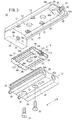
このリニアアクチュエータ10は、図1〜図7に示されるように、シリンダ本体12と、該シリンダ本体12の上部に設けられ、長手方向(矢印A、B方向)に沿って直線状に往復動作するスライドテーブル14と、前記シリンダ本体12とスライドテーブル14との間に介装され、前記スライドテーブル14を長手方向(矢印A、B方向)に沿って案内するガイド機構16と、前記スライドテーブル14の変位量を調整自在なストッパ機構18とを含む。
As shown in FIGS. 1 to 7, the
シリンダ本体12は、断面長方形状で長手方向(矢印A、B方向)に沿って所定長さで形成され、その上面には、略中央部に断面略円弧状に窪んだ凹部20が形成され、長手方向(矢印A、B方向)に沿って延在している。この凹部20には、シリンダ本体12とガイド機構16とを連結する連結ボルト22の挿通される一組のボルト孔24が貫通している。
The
また、シリンダ本体12の一側面には、図5に示されるように、圧力流体の供給・排出される第1及び第2ポート(流体出入ポート)26、28が該シリンダ本体12の長手方向と直交するように形成され、後述する一対の貫通孔(シリンダ室)30a、30bと連通している。さらに、シリンダ本体12の他側面には、長手方向(矢印A、B方向)に沿って二条のセンサ取付溝32がそれぞれ形成され、図示しないセンサが装着される。
Further, as shown in FIG. 5, first and second ports (fluid inlet / outlet ports) 26, 28 through which pressure fluid is supplied and discharged are provided on one side surface of the
シリンダ本体12の下面には、軸線上となる幅方向の中央部に一組のボルト孔24が形成され、下方より連結ボルト22が挿通される。そして、連結ボルト22は、その先端部が前記シリンダ本体12の上面より突出し、ガイド機構16のガイドブロック92に螺合されることによって互いに連結される。
A pair of
一方、シリンダ本体12の内部には、長手方向(矢印A、B方向)に沿って貫通した一対の貫通孔30a、30bが形成され、一方の貫通孔30aと他方の貫通孔30bとは、所定間隔離間して略平行に並設されている。貫通孔30a、30bには、外周面にシールリング34及びマグネット36が外周面に装着されたピストン37と、前記ピストン37に連結されたピストンロッド38とを含むシリンダ機構40がそれぞれ設けられる。このシリンダ機構40は、一対のピストン37及びピストンロッド38が一対の貫通孔30a、30bにそれぞれ内装されることによって構成される。
On the other hand, a pair of through-
貫通孔30a、30bの一端部は、キャップ42によって閉塞され、前記貫通孔30a、30bの他端部は、止め輪44を介して保持されるロッドホルダ46によって気密に閉塞される。なお、ロッドホルダ46の外周面には、環状溝を介してOリング48が装着され、貫通孔30a、30bとの間を通じた圧力流体の漏れを防止している。
One end portions of the through
さらに、一方の貫通孔30aは、第1及び第2ポート26、28とそれぞれ連通し、他方の貫通孔30bは、一方の貫通孔30aとの間に形成された一組の接続通路50を介して互いに連通している。すなわち、第1及び第2ポート26、28に供給された圧力流体は、一方の貫通孔30aへと導入された後、接続通路50を通じて他方に貫通孔30bにも導入される。この接続通路50は、貫通孔30a、30bの延在方向(矢印A、B方向)と直交するように形成されている。
Furthermore, one through
スライドテーブル14は、テーブル本体52と、該テーブル本体52の一端部に連結されるストッパ機構18と、前記テーブル本体52の他端部に連結されるエンドプレート54とを備え、前記エンドプレート54は、前記テーブル本体52に対して直交するように連結される。
The slide table 14 includes a table
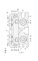
テーブル本体52は、長手方向(矢印A、B方向)に沿って所定厚さで延在するベース部56と、該ベース部56の両側部から直交するように下方へと延在した一対のガイド壁(ガイド部)58a、58bとからなり、前記ガイド壁58a、58bの内面には、後述するガイド機構16のボール(転動体)60が案内される第1ボール案内溝62が形成される。なお、第1ボール案内溝62は、断面略半円状に窪んで形成される。なお、ベース部56とガイド壁58a、58bとは、略同一の厚さ寸法で形成されている(図7参照)。
The table
また、テーブル本体52の一端部には、後述するストッパ機構18のホルダ部64を固定するためのボルト66aが挿通される一対の第1ボルト孔68が形成されると共に、他端部には、エンドプレート54を固定するためのボルト66bが挿通される一対の第2ボルト孔70が形成され、この第1及び第2ボルト孔68、70は、いずれもテーブル本体52の延在方向と直交方向に貫通している。
Further, a pair of first bolt holes 68 through which a
ベース部56には、その一端部と他端部との間に4個のワーク保持用孔部72が形成され、該ワーク保持用孔部72は、互いに所定間隔離間して配置され、スライドテーブル14をシリンダ本体12の上部に設けた際、ガイドブロック92の両側面に設けられる第2ボール案内溝74に対して前記シリンダ本体12及びガイドブロック92の幅方向における中心側となる位置に設けられる(図7参照)。
The
換言すれば、ワーク保持用孔部72は、スライドテーブル14において、ガイドブロック92の第2ボール案内溝74より内側となる位置に配置される。
In other words, the
エンドプレート54は、テーブル本体52の他端部に形成された第2ボルト孔70に挿通された2本のボルト66bによって固定され、シリンダ本体12の端面に臨むように設けられると共に、一組のロッド孔76a、76bに挿通されたピストンロッド38の端部がそれぞれ固定される。これにより、エンドプレート54を含むスライドテーブル14が、ピストンロッド38と共にシリンダ本体12の長手方向(矢印A、B方向)に沿って変位することとなる。
The
また、エンドプレート54には、一方のロッド孔76aと他方のロッド孔76bとの間となる位置に、ダンパ78の装着されるダンパ装着孔80が開口している。例えば、ゴム等の弾性材料からなるダンパ78が、シリンダ本体12側となるエンドプレート54の他側面側からダンパ装着孔80に装着された際、その端部が拡径すると共に前記他側面から突出する。
The
すなわち、エンドプレート54がスライドテーブル14と共に変位した際、該エンドプレート54の他側面より突出したダンパ78がシリンダ本体12の端面に当接することにより、前記エンドプレート54と前記シリンダ本体12とが直接当接した際に懸念される衝撃や衝撃音の発生が回避される。
That is, when the
ストッパ機構18は、テーブル本体52における一端部の下面に設けられるホルダ部64と、前記ホルダ部64に対して螺合されるストッパボルト82と、前記ストッパボルト82の進退動作を規制するロックナット84とを有し、シリンダ本体12に設けられたガイド機構16の端面に臨むように設けられる。
The
ホルダ部64は、ブロック状に形成され、スライドテーブル14を構成するテーブル本体52のベース部56に対して第1ボルト孔68を介して2本のボルト66aで上方から固定される。ホルダ部64の略中央部には、下方に向かって断面円弧状に膨出した第1膨出部86を有し、前記第1膨出部86を含むホルダ部64の中心部には、ストッパボルト82の螺合されるねじ孔88が形成され、前記テーブル本体52の延在方向と略平行に貫通している。
The
すなわち、ねじ孔88は、第1膨出部86を有するホルダ部64の略中央部に設けられることにより、該第1膨出部86を有していない場合と比較し、若干だけ下方に形成することができる。
That is, the
また、第1膨出部86は、ホルダ部64において軸線方向に沿って延在し、スライドテーブル14が長手方向に沿って変位する際、シリンダ本体12の凹部20に挿通される。
The first bulging
ストッパボルト82は、例えば、外周面にねじの刻設された軸状のスタッドボルトからなり、ホルダ部64のねじ孔88に螺合された状態で、該ねじ孔88から突出する長さで形成される。そして、ストッパボルト82には、ホルダ部64の端面から突出した部位にロックナット84が螺合される。
The
そして、ストッパボルト82をホルダ部64に対して螺回させることにより、該ストッパボルト82が軸線方向(矢印A、B方向)に沿って変位し、ガイド機構16に接近・離間する。例えば、ストッパボルト82を螺回させ所定長さだけガイド機構16側(矢印A方向)へと突出させた後、ロックナット84を螺回することにより移動させ前記ホルダ部64の側面に当接させることにより、前記ストッパボルト82の進退動作が規制される。
Then, when the
また、ストッパボルト82の端部には、ガイド機構16側に向かって所定長さだけ突出し、例えば、弾性材料からなる緩衝部90が形成される。この緩衝部90は、スライドテーブル14の変位作用下にストッパボルト82がガイド機構16の端面に当接する際の衝撃を緩和する目的で設けられる。
Further, at the end of the
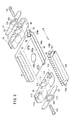
ガイド機構16は、図8及び図9に示されるように、幅広扁平状のガイドブロック92と、該ガイドブロック92に設けられ、ボール60を循環させる一対のボール循環部材94a、94bと、前記ガイドブロック92の長手方向に沿った両端部にそれぞれ装着される一組のカバー96と、前記カバー96の表面をそれぞれ覆う一組のカバープレート98とを含む。
As shown in FIGS. 8 and 9, the
ガイドブロック92の両側面には、長手方向に沿って第2ボール案内溝74が形成され、前記第2ボール案内溝74に近接する部位には、ボール循環部材94a、94bの挿入される一対の装着溝100a、100bが長手方向に沿って貫通している。第2ボール案内溝74は、断面半円状に形成され、ガイド機構16の上部にスライドテーブル14が配置された際、第1ボール案内溝62と対向する位置に形成される。
A second ball guide
装着溝100a、100bは、ガイドブロック92の下面に形成され、断面矩形状で下方及び長手方向に沿った両端部が開口している。
The mounting
ボール循環部材94a、94bは、装着溝100a、100bに対応して断面矩形状に形成され、その内部にボール60の循環するボール循環孔(第2循環通路)102が貫通すると共に、その両端部には、前記ボール60の循環方向を反転させる一組の反転部104a、104bがそれぞれ設けられる。反転部104a、104bは、断面半円状に形成され、その外周面にボール60の転動するボール溝が形成され、該ボール溝がボール循環孔102と連続的に接続されている。すなわち、ボール60が、ボール循環部材94a、94bにおいてボール循環孔102から反転部104a、104bのボール溝を介して該ボール循環部材94a、94bの外側に設けられた第1及び第2ボール案内溝(第1循環通路)62、74へと180°方向変換して転動する。
The
このボール循環部材94a、94bが、ガイドブロック92においてボール循環孔102が第1及び第2ボール案内溝62、74に対して下方となるように配置される。すなわち、ボール循環孔102と第1及び第2ボール案内溝62、74とが、鉛直方向(図7中、矢印C方向)に所定高さだけオフセットして設けられている。
The
また、反転部104a、104bは、ボール循環部材94a、94bをガイドブロック92の装着溝100a、100bに挿入した際、その平面部108がそれぞれガイドブロック92の両端面に当接し(図6参照)、前記ボール循環部材94a、94bのボール循環孔102と第2ボール案内溝74との間を接続している。
Further, when the
すなわち、図7に示されるように、ガイド機構16において、ボール循環孔102と第1及び第2ボール案内溝62、74とが反転部104a、104bによって斜め方向に接続されている。
That is, as shown in FIG. 7, in the
これにより、ボール循環部材94a、94bのボール循環孔102、ボール溝、スライドテーブル14の第1ボール案内溝62及びガイドブロック92の第2ボール案内溝74によって環状で連続するボール循環通路110が形成され、複数のボール60が前記ボール循環通路110に沿って転動することにより、スライドテーブル14をガイド機構16に沿って円滑に往復動作させる。
Thereby, the
カバー96は、ガイドブロック92の両端面を覆うように装着され、その中央部には、軸線方向に沿って貫通した孔部111が形成されると共に、前記孔部111を中心として上下方向に向かってそれぞれ断面円弧状に膨出した第2膨出部112を備える。この第2膨出部112は、シリンダ本体12の上部にガイド機構16が装着された際、該シリンダ本体12の凹部20内に挿入可能に設けられる。
一方、カバー96の内部には、反転部104a、104bの収容される空間部114が形成され、前記空間部114には、前記反転部104a、104bとの間を転動するボール60を保持する保持溝116が形成されている。この保持溝116は、反転部104a、104bの半径外側に断面円弧状に形成され、前記保持溝116と反転部104a、104bのボール溝との間をボール60が転動する。
On the other hand, a
カバープレート98の略中央部には、孔部118が形成され、カバー96の孔部111と同一直径且つ同軸上に形成される。そして、孔部111、118を通じてガイドブロック92の端面が外部に露呈すると共に、カバー96に対応して上下方向に断面円弧状に膨出した第3膨出部120を有する。この第3膨出部120は、カバー96の第2膨出部112と略同一の断面形状で形成され、シリンダ本体12の凹部20に挿入可能に設けられる。なお、上述したカバー96及びカバープレート98は、カバー固定用ボルト122を介してそれぞれガイドブロック92の端面に固定される。
A
そして、スライドテーブル14が往復動作した際、ストッパ機構18を構成するストッパボルト82が孔部118、111を介してガイドブロック92の端面に当接する。
When the slide table 14 reciprocates, the
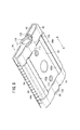
本発明の実施の形態に係るリニアアクチュエータ10は、基本的には以上のように構成されるものであり、次にその動作並びに作用効果について説明する。なお、図4に示されるように、スライドテーブル14を構成するエンドプレート54が、シリンダ本体12の端面に当接した状態を初期位置として説明する。
The
先ず、図示しない圧力流体供給源から圧力流体を第1ポート26へと導入する。この場合、第2流体出入ポートは、図示しない切換弁の操作下に大気開放状態としておく。
First, pressure fluid is introduced into the
この第1ポート26に供給された圧力流体は、一方の貫通孔30aへ供給されると共に、接続通路50を通じて他方の貫通孔30bへと供給され、ピストン37をロッドホルダ46側(矢印A方向)に向かって押圧する。これにより、ピストン37に連結されたピストンロッド38と共に、スライドテーブル14がシリンダ本体12から離間する方向へと変位する。
The pressure fluid supplied to the
この際、ガイド機構16を構成するボール60が、スライドテーブル14の変位に伴ってボール循環通路110に沿って転動することにより、前記スライドテーブル14が前記ガイド機構16によって軸線方向に沿って案内される。
At this time, the
そして、図10に示されるように、スライドテーブル14の一端部に設けられたストッパボルト82の端部が、ガイド機構16を構成するガイドブロック92の端面に当接することにより、前記スライドテーブル14の変位が停止した変位終端位置となる。
Then, as shown in FIG. 10, the end of the
このストッパ機構18は、ロックナット84を緩め、ストッパボルト82の進退動作を可能とした後、該ストッパボルト82を螺回させてホルダ部64の端面からの突出量を調整することにより、スライドテーブル14の変位量を調整することが可能である。
The
一方、図10に示される変位終端位置からスライドテーブル14を前記とは反対方向に変位させる場合には、第1ポート26に供給されていた圧力流体を第2ポート28に対して供給すると共に、前記第1ポート26を大気開放状態とする。これにより、第2ポート28から一対の貫通孔30a、30bへと供給された圧力流体によってピストン37がロッドホルダ46から離間する方向(矢印B方向)へと変位し、該ピストン37と共にピストンロッド38を介してスライドテーブル14がシリンダ本体12に接近する方向へと変位する。そして、スライドテーブル14を構成するエンドプレート54に設けられたダンパ78が、シリンダ本体12の端面に当接することにより初期位置へと復帰する。
On the other hand, when the slide table 14 is displaced from the displacement end position shown in FIG. 10 in the opposite direction, the pressure fluid supplied to the
以上のように、本実施の形態では、ガイド機構16を構成するガイドブロック92の下面に、下方に向かって開口した一対の装着溝100a、100bを形成すると共に、内部にボール60の循環するボール循環孔102を有したボール循環部材94a、94bを前記装着溝100a、100bに対してそれぞれ装着する構成としている。
As described above, in the present embodiment, a pair of mounting
そのため、ガイドブロック92に対してボール循環孔102を形成するための切削加工を行う必要がなく、製造コスト及び製造工程の削減を図ることができると共に、前記ガイドブロック92において、前記ボール循環孔102を加工する際に必要とされるスペースが不要となるため、該ガイドブロック92の厚さ寸法を抑制することができ、その結果として、前記ガイドブロック92の小型化を図ることが可能となる。
Therefore, it is not necessary to perform a cutting process for forming the
また、ガイド機構16において、ボール60の循環するボール循環通路110を、ボール循環部材94a、94bのボール循環孔102、反転部104a、104b、ガイドブロック92の第2ボール案内溝74及びスライドテーブル14の第1ボール案内溝62とから構成し、前記ボール循環孔102を、第1及び第2ボール案内溝62、74に対して鉛直下方向にオフセットさせて設けている。
In the
さらに、ガイドブロック92の第2ボール案内溝74が、その上方に設けられたスライドテーブル14のワーク保持用孔部72より外側となる位置に設けられている。そのため、例えば、ワーク保持用孔部72に取り付けられるボルトを締め付けすぎ、その先端が前記ガイドブロック92に接触して押圧した場合にも、ボール循環部材94a、94bが、シリンダ本体12側となるようにガイドブロック92の下方に設けられているため、前記ボルトの押圧力が付与されることが回避される。
Further, the second ball guide
その結果、ボール60を含むガイド機構16によるスライドテーブル14の案内機能が損なわれることがない。
As a result, the guide function of the slide table 14 by the
また、ガイドブロック92とは別部材のボール循環部材94a、94bを装着し、ボール循環孔102を設ける構成としているため、前記ボール循環孔102をガイドブロック92に対して加工等で直接形成する場合と比較し、該ガイドブロック92におけるボール循環孔102近傍の肉厚等を考慮する必要がなく、前記ボール循環部材94a、94bのボール循環孔102を、シリンダ本体12側に設けることが可能となる。その結果、ボール循環孔102を形成するためにガイドブロック92の厚さを増加させる必要がなく、その結果、前記ガイドブロック92の薄型化を図ることができる。
Further, since the
さらにまた、スライドテーブル14において、ベース部56の厚さ寸法と、一対のガイド壁58a、58bの厚さ寸法とが略同一となるように形成されているため、前記スライドテーブル14の薄肉化が可能となり、軽量化を図ることができる。さらに、スライドテーブル14を、プレス成形で製造することが可能となるため、製造コストの低減を図ることができる。
Furthermore, in the slide table 14, since the thickness dimension of the
また、エンドプレート54が、スライドテーブル14におけるベース部56の他端部に対して上方からボルト66bで固定される構成としているため、前記エンドプレート54を、その前方からスライドテーブル14のベース部56に対して固定する場合と比較し、前記ベース部56の厚さを薄くすることができる。その結果、ベース部56を含むスライドテーブル14の薄肉化を図ることができ、それに伴って、前記スライドテーブル14の軽量化を図ることができる。
Further, since the
なお、本発明に係るリニアアクチュエータは、上述の実施の形態に限らず、本発明の要旨を逸脱することなく、種々の構成を採り得ることはもちろんである。 Note that the linear actuator according to the present invention is not limited to the above-described embodiment, and various configurations can be adopted without departing from the gist of the present invention.
10…リニアアクチュエータ 12…シリンダ本体
14…スライドテーブル 16…ガイド機構
18…ストッパ機構 20…凹部
26…第1ポート 28…第2ポート
30a、30b…貫通孔 40…シリンダ機構
52…テーブル本体 54…エンドプレート
56…ベース部 58a、58b…ガイド壁
60…ボール 82…ストッパボルト
84…ロックナット 92…ガイドブロック
94a、94b…ボール循環部材 96…カバー
98…カバープレート 100a、100b…装着溝
104a、104b…反転部 110…ボール循環通路
DESCRIPTION OF
Claims (5)
前記流体出入ポートと連通し、前記圧力流体の導入されるシリンダ室を有したシリンダ本体と、
前記シリンダ本体の軸線方向に沿って往復動作するスライドテーブルと、
前記シリンダ室に沿って摺動自在に配設されるピストンを有し、前記ピストンの変位作用下に前記スライドテーブルを往復動作させるシリンダ機構と、
前記シリンダ本体に取り付けられ、複数の転動体の転動作用下に循環する第1循環通路が形成された扁平なガイドブロックを有し、前記スライドテーブルを前記シリンダ本体の軸線方向に沿って案内するガイド機構と、
前記ガイドブロックに装着され、前記転動体の循環する第2循環通路を有した循環部材と、
を備え、
前記ガイドブロックには、前記循環部材の装着される開口部が形成され、前記開口部は前記シリンダ本体側及び長手方向に沿った両端部が開口した断面矩形状に形成されると共に、前記循環部材が前記開口部に対応した断面矩形状、且つ、前記第2循環通路を内部に有した筒状に形成されることを特徴とするリニアアクチュエータ。 In the linear actuator that reciprocates the slide table along the axial direction of the cylinder body by introducing the pressure fluid from the fluid inlet / outlet port,
A cylinder body in communication with the fluid inlet / outlet port and having a cylinder chamber into which the pressure fluid is introduced;
A slide table that reciprocates along the axial direction of the cylinder body;
A cylinder mechanism having a piston slidably disposed along the cylinder chamber, and reciprocating the slide table under a displacement action of the piston;
A flat guide block that is attached to the cylinder body and has a first circulation passage that circulates under rolling motion of a plurality of rolling elements, and guides the slide table along an axial direction of the cylinder body; A guide mechanism;
A circulation member mounted on the guide block and having a second circulation passage through which the rolling elements circulate;
With
The guide block is formed with an opening to which the circulation member is mounted, and the opening is formed in a rectangular cross section with both ends along the cylinder body side and the longitudinal direction opened, and the circulation member Is formed in a cylindrical shape having a rectangular cross-section corresponding to the opening and the second circulation passage inside .
前記第1循環通路は、前記ガイドブロックの両側面に形成され、前記第2循環通路が、前記第1循環通路に対して前記シリンダ本体側に設けられることを特徴とするリニアアクチュエータ。 In the linear actuator according to claim 1 Symbol placement,
The linear actuator is characterized in that the first circulation passage is formed on both side surfaces of the guide block, and the second circulation passage is provided on the cylinder body side with respect to the first circulation passage.
前記スライドテーブルには、ワークを固定するためのワーク保持孔が形成され、前記ワーク保持孔が、前記第1循環通路に対して軸線方向と直交する幅方向の内側に設けられることを特徴とするリニアアクチュエータ。 The linear actuator according to claim 1 or 2 ,
A work holding hole for fixing a work is formed in the slide table, and the work holding hole is provided inside the width direction perpendicular to the axial direction with respect to the first circulation passage. Linear actuator.
前記スライドテーブルは、前記ガイドブロックの上部に設けられるベース部と、
前記ベース部の両側部から下方に向かって延在する一組のガイド部と、
を備え、
前記ベース部と前記ガイド部とが、略同一の厚さ寸法で形成されることを特徴とするリニアアクチュエータ。 In the linear actuator of any one of Claims 1-3 ,
The slide table includes a base portion provided on an upper portion of the guide block;
A set of guide portions extending downward from both side portions of the base portion;
With
The linear actuator, wherein the base portion and the guide portion are formed with substantially the same thickness.
前記スライドテーブルには、ピストンロッドを介して前記ピストンと連結されるエンドプレートを備え、前記エンドプレートは、前記ベース部の下方に設けられ、該ベース部に対して上方から挿入される締結部材によって連結されることを特徴とするリニアアクチュエータ。 The linear actuator according to claim 4 , wherein
The slide table includes an end plate connected to the piston via a piston rod, and the end plate is provided below the base portion and is fastened by a fastening member inserted from above into the base portion. A linear actuator characterized by being connected.
Priority Applications (6)
| Application Number | Priority Date | Filing Date | Title |
|---|---|---|---|
| JP2010000564A JP5574152B2 (en) | 2010-01-05 | 2010-01-05 | Linear actuator |
| US12/813,879 US8683911B2 (en) | 2010-01-05 | 2010-06-11 | Linear actuator |
| TW99119239A TWI467095B (en) | 2010-01-05 | 2010-06-14 | Linear actuator |
| DE102010024907A DE102010024907A1 (en) | 2010-01-05 | 2010-06-24 | Linear actuator |
| KR1020100061823A KR101152218B1 (en) | 2010-01-05 | 2010-06-29 | Linear actuator |
| CN201010246664.8A CN102116330B (en) | 2010-01-05 | 2010-07-30 | Linear actuator |
Applications Claiming Priority (1)
| Application Number | Priority Date | Filing Date | Title |
|---|---|---|---|
| JP2010000564A JP5574152B2 (en) | 2010-01-05 | 2010-01-05 | Linear actuator |
Publications (3)
| Publication Number | Publication Date |
|---|---|
| JP2011140968A JP2011140968A (en) | 2011-07-21 |
| JP2011140968A5 JP2011140968A5 (en) | 2013-02-14 |
| JP5574152B2 true JP5574152B2 (en) | 2014-08-20 |
Family
ID=44215222
Family Applications (1)
| Application Number | Title | Priority Date | Filing Date |
|---|---|---|---|
| JP2010000564A Expired - Fee Related JP5574152B2 (en) | 2010-01-05 | 2010-01-05 | Linear actuator |
Country Status (6)
| Country | Link |
|---|---|
| US (1) | US8683911B2 (en) |
| JP (1) | JP5574152B2 (en) |
| KR (1) | KR101152218B1 (en) |
| CN (1) | CN102116330B (en) |
| DE (1) | DE102010024907A1 (en) |
| TW (1) | TWI467095B (en) |
Families Citing this family (6)
| Publication number | Priority date | Publication date | Assignee | Title |
|---|---|---|---|---|
| CN103291683A (en) * | 2012-02-24 | 2013-09-11 | 刘素华 | Method for utilizing rolling friction to centralize piston rod to do reciprocating motion and actuating device for utilizing rolling friction to centralize piston rod to do reciprocating motion through implementing method |
| WO2013123826A1 (en) * | 2012-02-24 | 2013-08-29 | Liu Suhua | Engine piston rolling friction or suspension friction method, and wear-resistant piston engine using said method |
| CN103912467A (en) * | 2012-12-28 | 2014-07-09 | 刘素华 | Method for realizing reciprocating motion rolling friction of slurry pump and reciprocating motion rolling friction of slurry pump implementing method |
| CN108150630A (en) * | 2018-02-08 | 2018-06-12 | 东莞市顺纳电子有限公司 | A kind of round-trip driver of no bar |
| JP6914477B2 (en) * | 2018-09-12 | 2021-08-04 | Smc株式会社 | Fluid pressure cylinder |
| KR102273658B1 (en) * | 2019-11-12 | 2021-07-06 | 주식회사 피앤엠 | Thin Type Precise Linear Actuator |
Family Cites Families (24)
| Publication number | Priority date | Publication date | Assignee | Title |
|---|---|---|---|---|
| US3859147A (en) * | 1972-03-10 | 1975-01-07 | Carpenter Technology Corp | Hot hard stainless steel |
| CA1201041A (en) | 1982-06-28 | 1986-02-25 | Thomas J. Frankhouse | Molded terminal for remote control assembly (lollipop) |
| JPS5976733A (en) * | 1982-10-25 | 1984-05-01 | Hiroshi Teramachi | Table for linear sliding |
| US4748866A (en) | 1986-07-03 | 1988-06-07 | Weyer Paul P | Linear helical actuator |
| US5363741A (en) | 1992-12-24 | 1994-11-15 | Smc Kabushiki Kaisha | Slide actuator |
| JP3795968B2 (en) * | 1996-08-13 | 2006-07-12 | Smc株式会社 | Linear actuator |
| GB2316132B (en) * | 1996-08-13 | 1999-02-17 | Smc Kk | Linear actuator |
| CN1077352C (en) * | 1997-02-05 | 2002-01-02 | Smc株式会社 | Actuator and apparatus for controlling same |
| JP3543065B2 (en) * | 1999-04-16 | 2004-07-14 | Smc株式会社 | Linear actuator |
| TW451031B (en) * | 1999-10-01 | 2001-08-21 | Smc Corp | Linear actuator with air buffer mechanism |
| JP3516910B2 (en) | 1999-10-18 | 2004-04-05 | Smc株式会社 | Transfer equipment |
| IT1316047B1 (en) * | 2000-02-11 | 2003-03-26 | Gimatic Spa | LINEAR HANDLING UNIT |
| JP4273476B2 (en) * | 2000-02-18 | 2009-06-03 | Smc株式会社 | Linear actuator |
| JP2003222104A (en) * | 2002-01-31 | 2003-08-08 | Smc Corp | Linear actuator |
| CN100427764C (en) * | 2003-02-10 | 2008-10-22 | 日本精工株式会社 | Separator linear guider therewith and linear motion device |
| JP4525155B2 (en) * | 2004-04-26 | 2010-08-18 | Smc株式会社 | Linear actuator |
| US7290478B2 (en) * | 2005-01-28 | 2007-11-06 | Phd, Inc. | Stop for a slide assembly |
| CN100451360C (en) | 2005-02-05 | 2009-01-14 | 上银科技股份有限公司 | Linear guide rail circulating device |
| CN2837045Y (en) | 2005-08-15 | 2006-11-15 | 蔡庆明 | Vertical compression mode locking device for machinery equipment |
| JP2007218296A (en) | 2006-02-15 | 2007-08-30 | New-Era Co Ltd | Actuator |
| TWM310272U (en) | 2006-08-31 | 2007-04-21 | Hiwin Tech Corp | Circulation apparatus for linear guide-ways |
| JP4992151B2 (en) | 2006-11-30 | 2012-08-08 | Smc株式会社 | Linear actuator |
| JP5089369B2 (en) | 2007-12-19 | 2012-12-05 | 豊和工業株式会社 | Magnet type rodless cylinder |
| TW200934963A (en) | 2008-02-01 | 2009-08-16 | Hiwin Tech Corp | Retainer of linear guideway |
-
2010
- 2010-01-05 JP JP2010000564A patent/JP5574152B2/en not_active Expired - Fee Related
- 2010-06-11 US US12/813,879 patent/US8683911B2/en not_active Expired - Fee Related
- 2010-06-14 TW TW99119239A patent/TWI467095B/en not_active IP Right Cessation
- 2010-06-24 DE DE102010024907A patent/DE102010024907A1/en not_active Withdrawn
- 2010-06-29 KR KR1020100061823A patent/KR101152218B1/en active IP Right Grant
- 2010-07-30 CN CN201010246664.8A patent/CN102116330B/en not_active Expired - Fee Related
Also Published As
| Publication number | Publication date |
|---|---|
| TWI467095B (en) | 2015-01-01 |
| CN102116330B (en) | 2014-11-12 |
| TW201124631A (en) | 2011-07-16 |
| JP2011140968A (en) | 2011-07-21 |
| US20110162519A1 (en) | 2011-07-07 |
| KR101152218B1 (en) | 2012-06-11 |
| DE102010024907A1 (en) | 2011-07-07 |
| US8683911B2 (en) | 2014-04-01 |
| KR20110081020A (en) | 2011-07-13 |
| DE102010024907A8 (en) | 2011-11-10 |
| CN102116330A (en) | 2011-07-06 |
Similar Documents
| Publication | Publication Date | Title |
|---|---|---|
| JP5574152B2 (en) | Linear actuator | |
| JP5704528B2 (en) | Linear actuator | |
| JP4992151B2 (en) | Linear actuator | |
| TWI273178B (en) | Linear actuator | |
| JP6011883B2 (en) | Linear actuator | |
| JP3896550B2 (en) | Linear actuator | |
| KR20080048970A (en) | Fluid pressure cylinder | |
| JP6252952B2 (en) | Rotary actuator | |
| KR101866813B1 (en) | Fluid pressure cylinder | |
| KR20110110723A (en) | Cap for use in fluid pressure device and fixing method therefor | |
| JP5504539B2 (en) | Linear actuator | |
| JP6229739B2 (en) | Linear actuator | |
| JP2003222104A (en) | Linear actuator | |
| JP6229623B2 (en) | Fluid pressure cylinder and actuator | |
| JP2002168206A (en) | Fluid pressure cylinder | |
| TWI587975B (en) | Linear actuator | |
| KR20150018984A (en) | Check valves for hydraulic cylinders | |
| JPH1089312A (en) | Linear actuator | |
| JPH0445833Y2 (en) | ||
| KR20190073361A (en) | Closing device | |
| JP2007046789A (en) | Linear actuator | |
| JP2000283113A (en) | Linear actuator | |
| JP2007326177A (en) | Holding device |
Legal Events
| Date | Code | Title | Description |
|---|---|---|---|
| A521 | Request for written amendment filed |
Free format text: JAPANESE INTERMEDIATE CODE: A523 Effective date: 20121226 |
|
| A621 | Written request for application examination |
Free format text: JAPANESE INTERMEDIATE CODE: A621 Effective date: 20121226 |
|
| A977 | Report on retrieval |
Free format text: JAPANESE INTERMEDIATE CODE: A971007 Effective date: 20131022 |
|
| A131 | Notification of reasons for refusal |
Free format text: JAPANESE INTERMEDIATE CODE: A131 Effective date: 20131029 |
|
| A521 | Request for written amendment filed |
Free format text: JAPANESE INTERMEDIATE CODE: A523 Effective date: 20131224 |
|
| TRDD | Decision of grant or rejection written | ||
| A01 | Written decision to grant a patent or to grant a registration (utility model) |
Free format text: JAPANESE INTERMEDIATE CODE: A01 Effective date: 20140520 |
|
| A61 | First payment of annual fees (during grant procedure) |
Free format text: JAPANESE INTERMEDIATE CODE: A61 Effective date: 20140618 |
|
| R150 | Certificate of patent or registration of utility model |
Ref document number: 5574152 Country of ref document: JP Free format text: JAPANESE INTERMEDIATE CODE: R150 |
|
| R250 | Receipt of annual fees |
Free format text: JAPANESE INTERMEDIATE CODE: R250 |
|
| R250 | Receipt of annual fees |
Free format text: JAPANESE INTERMEDIATE CODE: R250 |
|
| R250 | Receipt of annual fees |
Free format text: JAPANESE INTERMEDIATE CODE: R250 |
|
| R250 | Receipt of annual fees |
Free format text: JAPANESE INTERMEDIATE CODE: R250 |
|
| LAPS | Cancellation because of no payment of annual fees |