JP5570866B2 - Image processing apparatus, method of operating image processing apparatus, and image processing program - Google Patents
Image processing apparatus, method of operating image processing apparatus, and image processing program Download PDFInfo
- Publication number
- JP5570866B2 JP5570866B2 JP2010105755A JP2010105755A JP5570866B2 JP 5570866 B2 JP5570866 B2 JP 5570866B2 JP 2010105755 A JP2010105755 A JP 2010105755A JP 2010105755 A JP2010105755 A JP 2010105755A JP 5570866 B2 JP5570866 B2 JP 5570866B2
- Authority
- JP
- Japan
- Prior art keywords
- region
- closed region
- unit
- energy
- image
- Prior art date
- Legal status (The legal status is an assumption and is not a legal conclusion. Google has not performed a legal analysis and makes no representation as to the accuracy of the status listed.)
- Active
Links
- 238000012545 processing Methods 0.000 title claims description 124
- 238000000034 method Methods 0.000 title claims description 105
- 230000002159 abnormal effect Effects 0.000 claims description 102
- 238000004364 calculation method Methods 0.000 claims description 93
- 230000010354 integration Effects 0.000 claims description 82
- 238000001514 detection method Methods 0.000 claims description 41
- 238000012937 correction Methods 0.000 claims description 28
- 238000005452 bending Methods 0.000 claims description 15
- 238000010521 absorption reaction Methods 0.000 claims description 5
- 230000005856 abnormality Effects 0.000 claims 1
- 230000008569 process Effects 0.000 description 76
- 238000010586 diagram Methods 0.000 description 56
- 238000000605 extraction Methods 0.000 description 15
- 230000008859 change Effects 0.000 description 11
- 230000001419 dependent effect Effects 0.000 description 10
- 102000001554 Hemoglobins Human genes 0.000 description 7
- 108010054147 Hemoglobins Proteins 0.000 description 7
- 238000003708 edge detection Methods 0.000 description 7
- 230000000877 morphologic effect Effects 0.000 description 7
- 238000004891 communication Methods 0.000 description 6
- 230000007423 decrease Effects 0.000 description 6
- 239000002775 capsule Substances 0.000 description 5
- 238000002372 labelling Methods 0.000 description 5
- 238000012986 modification Methods 0.000 description 5
- 230000004048 modification Effects 0.000 description 5
- 238000003672 processing method Methods 0.000 description 5
- 241000282341 Mustela putorius furo Species 0.000 description 4
- 238000004458 analytical method Methods 0.000 description 4
- 230000006870 function Effects 0.000 description 4
- 238000003384 imaging method Methods 0.000 description 4
- 230000003902 lesion Effects 0.000 description 4
- 230000015654 memory Effects 0.000 description 4
- 239000002245 particle Substances 0.000 description 4
- 208000004434 Calcinosis Diseases 0.000 description 3
- 238000003745 diagnosis Methods 0.000 description 3
- 230000000694 effects Effects 0.000 description 3
- 230000000740 bleeding effect Effects 0.000 description 2
- 238000005516 engineering process Methods 0.000 description 2
- 210000001035 gastrointestinal tract Anatomy 0.000 description 2
- 238000009499 grossing Methods 0.000 description 2
- 230000031700 light absorption Effects 0.000 description 2
- 230000003595 spectral effect Effects 0.000 description 2
- 206010006187 Breast cancer Diseases 0.000 description 1
- 208000026310 Breast neoplasm Diseases 0.000 description 1
- 210000004204 blood vessel Anatomy 0.000 description 1
- 230000000994 depressogenic effect Effects 0.000 description 1
- 238000013461 design Methods 0.000 description 1
- 238000002059 diagnostic imaging Methods 0.000 description 1
- 230000004069 differentiation Effects 0.000 description 1
- 239000000284 extract Substances 0.000 description 1
- 230000014509 gene expression Effects 0.000 description 1
- 230000012447 hatching Effects 0.000 description 1
- 230000000717 retained effect Effects 0.000 description 1
- 239000013598 vector Substances 0.000 description 1
Images


Classifications
-
- G—PHYSICS
- G06—COMPUTING; CALCULATING OR COUNTING
- G06T—IMAGE DATA PROCESSING OR GENERATION, IN GENERAL
- G06T7/00—Image analysis
- G06T7/0002—Inspection of images, e.g. flaw detection
- G06T7/0012—Biomedical image inspection
-
- G—PHYSICS
- G06—COMPUTING; CALCULATING OR COUNTING
- G06T—IMAGE DATA PROCESSING OR GENERATION, IN GENERAL
- G06T7/00—Image analysis
- G06T7/10—Segmentation; Edge detection
- G06T7/12—Edge-based segmentation
-
- G—PHYSICS
- G06—COMPUTING; CALCULATING OR COUNTING
- G06T—IMAGE DATA PROCESSING OR GENERATION, IN GENERAL
- G06T7/00—Image analysis
- G06T7/10—Segmentation; Edge detection
- G06T7/149—Segmentation; Edge detection involving deformable models, e.g. active contour models
-
- G—PHYSICS
- G06—COMPUTING; CALCULATING OR COUNTING
- G06T—IMAGE DATA PROCESSING OR GENERATION, IN GENERAL
- G06T7/00—Image analysis
- G06T7/10—Segmentation; Edge detection
- G06T7/187—Segmentation; Edge detection involving region growing; involving region merging; involving connected component labelling
-
- G—PHYSICS
- G06—COMPUTING; CALCULATING OR COUNTING
- G06T—IMAGE DATA PROCESSING OR GENERATION, IN GENERAL
- G06T2207/00—Indexing scheme for image analysis or image enhancement
- G06T2207/10—Image acquisition modality
- G06T2207/10024—Color image
-
- G—PHYSICS
- G06—COMPUTING; CALCULATING OR COUNTING
- G06T—IMAGE DATA PROCESSING OR GENERATION, IN GENERAL
- G06T2207/00—Indexing scheme for image analysis or image enhancement
- G06T2207/10—Image acquisition modality
- G06T2207/10068—Endoscopic image
-
- G—PHYSICS
- G06—COMPUTING; CALCULATING OR COUNTING
- G06T—IMAGE DATA PROCESSING OR GENERATION, IN GENERAL
- G06T2207/00—Indexing scheme for image analysis or image enhancement
- G06T2207/20—Special algorithmic details
- G06T2207/20021—Dividing image into blocks, subimages or windows
-
- G—PHYSICS
- G06—COMPUTING; CALCULATING OR COUNTING
- G06T—IMAGE DATA PROCESSING OR GENERATION, IN GENERAL
- G06T2207/00—Indexing scheme for image analysis or image enhancement
- G06T2207/20—Special algorithmic details
- G06T2207/20112—Image segmentation details
- G06T2207/20116—Active contour; Active surface; Snakes
-
- G—PHYSICS
- G06—COMPUTING; CALCULATING OR COUNTING
- G06T—IMAGE DATA PROCESSING OR GENERATION, IN GENERAL
- G06T2207/00—Indexing scheme for image analysis or image enhancement
- G06T2207/30—Subject of image; Context of image processing
- G06T2207/30004—Biomedical image processing
- G06T2207/30028—Colon; Small intestine
-
- G—PHYSICS
- G06—COMPUTING; CALCULATING OR COUNTING
- G06T—IMAGE DATA PROCESSING OR GENERATION, IN GENERAL
- G06T2207/00—Indexing scheme for image analysis or image enhancement
- G06T2207/30—Subject of image; Context of image processing
- G06T2207/30004—Biomedical image processing
- G06T2207/30092—Stomach; Gastric
Landscapes
- Engineering & Computer Science (AREA)
- Computer Vision & Pattern Recognition (AREA)
- Theoretical Computer Science (AREA)
- General Physics & Mathematics (AREA)
- Physics & Mathematics (AREA)
- Nuclear Medicine, Radiotherapy & Molecular Imaging (AREA)
- Quality & Reliability (AREA)
- Radiology & Medical Imaging (AREA)
- Health & Medical Sciences (AREA)
- Medical Informatics (AREA)
- General Health & Medical Sciences (AREA)
- Software Systems (AREA)
- Image Analysis (AREA)
- Image Processing (AREA)
- Endoscopes (AREA)
- Instruments For Viewing The Inside Of Hollow Bodies (AREA)
Description
本発明は、管腔内を撮像した管腔内画像を処理する画像処理装置、画像処理方法、および画像処理プログラムに関するものである。 The present invention relates to an image processing apparatus, an image processing method, and an image processing program for processing an intraluminal image obtained by imaging the inside of a lumen.
従来から、患者等の被検者の体内に導入されて体内管腔内を観察する医用観察装置として、内視鏡が広く普及している。また、近年では、カプセル型の筐体内部に撮像装置やこの撮像装置によって撮像された画像データを体外に無線送信する通信装置等を備えた飲み込み型の内視鏡(カプセル内視鏡)が開発されている。これらの医用観察装置によって撮像された体内管腔内の画像(管腔内画像)の観察・診断は、多くの経験を必要とするため、医師による診断を補助する医療診断支援機能が望まれている。この機能を実現する画像認識技術の1つとして、管腔内画像から病変等の異常部を自動的に検出して医師等に提示する技術が提案されている。 2. Description of the Related Art Endoscopes have been widely used as medical observation apparatuses that are introduced into the body of a subject such as a patient and observe the inside of a body lumen. In recent years, a swallowable endoscope (capsule endoscope) has been developed that includes an imaging device inside a capsule-type housing and a communication device that wirelessly transmits image data captured by the imaging device to the outside of the body. Has been. Observation / diagnosis of images in the body lumen (intraluminal images) imaged by these medical observation devices requires a lot of experience, and therefore a medical diagnosis support function for assisting diagnosis by a doctor is desired. Yes. As one of image recognition techniques for realizing this function, a technique for automatically detecting an abnormal part such as a lesion from an intraluminal image and presenting it to a doctor or the like has been proposed.
例えば、特許文献1には、形状依存性フィルタを用い、粗大構造や線構造の影響を受けることなく乳癌の癌化部分の特徴の1つである微小石灰化陰影の候補を安定的に検出する技術が開示されている。この特許文献1では、想定される微小石灰化陰影の形状をもとに、撮影条件や読取り条件、画像コントラスト、微小石灰化陰影のサイズといった各種条件、あるいはこれらを組み合わせた条件等に応じてフィルタ特性を最適化した第2の形状依存性フィルタを事前に準備しておく。そして、先ず、モルフォロジフィルタ(例えば非特許文献1,2を参照)である第1の形状依存性フィルタを用いて画像中の直線構造を除去することで、微細構造部分を表す微細構造画像を生成する。その後、微細構造画像に対して準備しておいた第2の形状依存性フィルタを用いた強調処理を施すことにより、周囲(第1の形状依存性フィルタで除ききれなかった粗大構造部分や線構造部分等を含む微小石灰化陰影候補以外の部分)と比較して相対的に微小石灰化陰影候補のみを強調した強調処理済画像を生成している。
For example,
ところで、上記した内視鏡やカプセル内視鏡等の医用観察装置によって撮像される管腔内画像には、例えば消化管内壁の粘膜構造の折りたたみやうねりによって発生する溝や、粘膜ひだの輪郭等、曲率が大きく、折れ曲がったような箇所が多く存在する。このため、特許文献1を管腔内画像に適用し、病変等の異常部を検出しようとすると、直線構造を除去する第1の形状依存性フィルタ(モルフォロジフィルタ)では、フィルタのサイズに依存して、前述のような生体組織が形成する溝位置や輪郭部分等のように、曲率が大きく折れ曲がったような箇所が微細構造画像に残ってしまう。また、特許文献1の第2の形状依存性フィルタは特定の形状(微小石灰化陰影の形状)を強調するためのものであるが、管腔内画像に映る異常部は決まった形状を持たない。このため、特許文献1のように、異常部の形状を事前に想定し、第1の形状依存性フィルタで残る構造、例えば前述のような曲率が大きく折れ曲がったような箇所と異常部とを区別するための最適な形状依存性フィルタを設計するのは難しい。したがって、2種類の形状依存性フィルタを組み合わせても、異常部を溝位置や輪郭部分と区別して検出するのは困難であった。
By the way, in the intraluminal image captured by the medical observation apparatus such as the endoscope or the capsule endoscope described above, for example, a groove generated by folding or undulation of the mucosal structure of the inner wall of the digestive tract, the contour of the mucous fold, There are many places where the curvature is large and bent. For this reason, when applying
本発明は、上記に鑑み為されたものであって、管腔内画像から異常部を精度良く検出することができる画像処理装置、画像処理方法、および画像処理プログラムを提供することを目的とする。 The present invention has been made in view of the above, and an object thereof is to provide an image processing apparatus, an image processing method, and an image processing program capable of accurately detecting an abnormal part from an intraluminal image. .
上記した課題を解決し、目的を達成するための、本発明のある態様にかかる画像処理装置は、管腔内画像から異常部を検出する画像処理装置であって、前記管腔内画像の画素値をもとに、各画素の勾配情報を算出する勾配情報算出手段と、前記勾配情報をもとに、勾配の強度が所定の値以上である画素を領域の内部に含まず、かつ、領域の境界が該領域の内側に所定の曲率以上で屈曲しないことを条件として該条件を満たす閉領域を作成する閉領域作成手段と、前記閉領域の内部から異常部を検出する異常部検出手段と、を備えることを特徴とする。 In order to solve the above-described problems and achieve the object, an image processing apparatus according to an aspect of the present invention is an image processing apparatus that detects an abnormal part from an intraluminal image, and the pixel of the intraluminal image A gradient information calculation unit that calculates gradient information of each pixel based on the value, and a pixel whose gradient strength is a predetermined value or more based on the gradient information is not included in the region, and the region A closed region creating means for creating a closed region that satisfies the condition on the condition that the boundary of the region does not bend inside the region with a predetermined curvature or more, and an abnormal part detecting unit for detecting an abnormal part from the inside of the closed region It is characterized by providing.
この態様にかかる画像処理装置によれば、管腔内画像を構成する勾配の強度が所定の値以上である画素を領域の内部に含まず、かつ、領域の境界が該領域の内側に所定の曲率以上で屈曲しないことを条件としてこの条件を満たす閉領域を作成することができる。管腔内画像には、生体組織が形成する溝位置や輪郭部分が映るが、この溝位置や輪郭部分は、管腔内画像中で勾配の強度が所定の値以上である部分や、輪郭がある程度の曲率で屈曲する部分として現れる。したがって、前述の溝位置や輪郭部分を内部や境界に含まないように閉領域を作成することができる。そして、この閉領域の内部から異常部を検出することができる。これによれば、溝位置や輪郭部分を異常部として誤検出する事態を防止し、管腔内画像から異常部を精度良く検出することができるという効果を奏する。 According to the image processing apparatus according to this aspect, pixels that have a gradient intensity equal to or greater than a predetermined value constituting the intraluminal image are not included in the region, and the boundary of the region is set to the predetermined value inside the region. A closed region that satisfies this condition can be created on condition that it does not bend beyond the curvature. In the intraluminal image, the groove position and contour portion formed by the living tissue are reflected. The groove position and contour portion are a portion of the intraluminal image where the strength of the gradient is equal to or greater than a predetermined value or a contour. It appears as a bent part with a certain degree of curvature. Therefore, it is possible to create a closed region so as not to include the above-described groove position and contour portion in the inside and the boundary. An abnormal part can be detected from the inside of the closed region. According to this, it is possible to prevent a situation in which a groove position or a contour portion is erroneously detected as an abnormal part, and to detect an abnormal part with high accuracy from an intraluminal image.
また、本発明の別の態様にかかる画像処理方法は、管腔内画像から異常部を検出する画像処理方法であって、前記管腔内画像の画素値をもとに、各画素の勾配情報を算出する勾配情報算出工程と、前記勾配情報をもとに、勾配の強度が所定の値以上である画素を領域の内部に含まず、かつ、領域の境界が該領域の内側に所定の曲率以上で屈曲しないことを条件として該条件を満たす閉領域を作成する閉領域作成工程と、前記閉領域の内部から異常部を検出する異常部検出工程と、を含むことを特徴とする。 An image processing method according to another aspect of the present invention is an image processing method for detecting an abnormal part from an intraluminal image, and the gradient information of each pixel based on the pixel value of the intraluminal image. A gradient information calculation step for calculating the gradient, and based on the gradient information, pixels whose gradient strength is equal to or greater than a predetermined value are not included in the region, and the boundary of the region is inside the region with a predetermined curvature A closed region creating step for creating a closed region that satisfies the condition on the condition that it does not bend, and an abnormal part detecting step for detecting an abnormal part from the inside of the closed region are included.
また、本発明の別の態様にかかる画像処理プログラムは、コンピュータに、管腔内画像から異常部を検出させるための画像処理プログラムであって、前記管腔内画像の画素値をもとに、各画素の勾配情報を算出する勾配情報算出手順と、前記勾配情報をもとに、勾配の強度が所定の値以上である画素を領域の内部に含まず、かつ、領域の境界が該領域の内側に所定の曲率以上で屈曲しないことを条件として該条件を満たす閉領域を作成する閉領域作成手順と、前記閉領域の内部から異常部を検出する異常部検出手順と、を前記コンピュータに実行させることを特徴とする。 An image processing program according to another aspect of the present invention is an image processing program for causing a computer to detect an abnormal part from an intraluminal image, and based on the pixel value of the intraluminal image, Based on the gradient information calculation procedure for calculating the gradient information of each pixel and the gradient information, pixels whose gradient strength is equal to or greater than a predetermined value are not included in the region, and the boundary of the region is The computer executes a closed region creation procedure for creating a closed region that satisfies the condition on condition that the inside does not bend at a predetermined curvature or more, and an abnormal part detection procedure for detecting an abnormal part from the inside of the closed region. It is characterized by making it.
本発明によれば、管腔内画像から異常部を精度良く検出することができる。 According to the present invention, an abnormal part can be detected with high accuracy from an intraluminal image.
以下、図面を参照し、本発明の好適な実施の形態について説明する。なお、この実施の形態によって本発明が限定されるものではない。また、各図面の記載において、同一部分には同一の符号を付して示している。 Hereinafter, preferred embodiments of the present invention will be described with reference to the drawings. Note that the present invention is not limited to the embodiments. Moreover, in description of each drawing, the same code | symbol is attached | subjected and shown to the same part.
本実施の形態の画像処理装置は、例えば内視鏡やカプセル内視鏡等の医用観察装置が被検者の体内の消化管等の管腔内を撮像した画像(管腔内画像)を処理するものであり、具体的には、管腔内画像から例えば病変や出血部位等の異常部を検出する処理を行うものである。上記したように、管腔内画像には、粘膜構造等の生体組織が形成する溝の陰影や輪郭が映る。本実施の形態では、この溝位置や輪郭部分を異常部として誤検出する事態を防止するため、管腔内画像中においてこれら溝位置や輪郭部分を内部や境界に含まないように閉領域を作成し、作成した閉領域毎に異常部を検出する。なお、本実施の形態において、管腔内画像は、例えば、画素毎にR(赤),G(緑),B(青)の各波長成分に対する画素値を持つカラー画像である。 The image processing apparatus according to the present embodiment processes an image (intraluminal image) in which a medical observation apparatus such as an endoscope or a capsule endoscope images a lumen such as a digestive tract in a body of a subject. Specifically, a process for detecting an abnormal portion such as a lesion or a bleeding site from an intraluminal image is performed. As described above, the intraluminal image shows shadows and contours of grooves formed by living tissue such as mucosal structures. In this embodiment, in order to prevent a situation in which the groove position or the contour part is erroneously detected as an abnormal part, a closed region is created so that the groove position or the contour part is not included in the inside or the boundary in the intraluminal image. Then, an abnormal part is detected for each created closed region. In the present embodiment, the intraluminal image is, for example, a color image having pixel values for each wavelength component of R (red), G (green), and B (blue) for each pixel.
(実施の形態1)
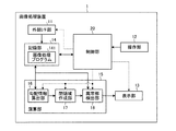
先ず、実施の形態1の画像処理装置について説明する。図1は、実施の形態1の画像処理装置1の機能構成例を説明するブロック図である。また、図2は、演算部15を構成する勾配情報算出部16の構成例を説明するブロック図であり、図3は、閉領域作成部17の構成例を説明するブロック図であり、図4は、異常部検出部18の構成例を説明するブロック図である。なお、図1〜図4の各図中において、画像処理装置1の各部間を接続して画像信号等のデータ信号を伝送するデータ信号線を実線で示し、制御信号を伝送する制御信号線を破線で示している。
(Embodiment 1)
First, the image processing apparatus according to the first embodiment will be described. FIG. 1 is a block diagram illustrating an exemplary functional configuration of the
図1に示すように、実施の形態1の画像処理装置1は、外部インターフェース(I/F)部11と、操作部12と、表示部13と、記録部14と、演算部15と、画像処理装置1全体の動作を制御する制御部20とを備える。
As shown in FIG. 1, the
外部I/F部11は、医用観察装置によって撮像された管腔内画像の画像データを取得するためのものであり、この外部I/F部11によって取得された画像データは記録部14に記録され、演算部15によって処理された後、必要に応じて適宜表示部13に表示される。外部I/F部11は、例えば医用観察装置がカプセル内視鏡の場合等のように医用観察装置との間の画像データの受け渡しに可搬型の記録媒体が使用される場合であれば、この記録媒体を着脱自在に装着して保存された管腔内画像の画像データを読み出すリーダ装置で構成される。また、医用観察装置によって撮像された管腔内画像の画像データを保存しておくサーバを適所に設置し、このサーバから取得する構成の場合には、外部I/F部11を、サーバと接続するための通信装置等で構成する。そして、この外部I/F部11を介してサーバとデータ通信を行い、管腔内画像の画像データを取得する。また、この他、内視鏡等の医用観察装置からの画像信号をケーブルを介して入力するインターフェース装置等で構成してもよい。
The external I /
操作部12は、例えばキーボードやマウス、タッチパネル、各種スイッチ等によって実現されるものであり、操作信号を制御部20に出力する。表示部13は、LCDやELディスプレイ等の表示装置によって実現されるものであり、制御部20の制御のもと、カプセル内視鏡3で撮像された画像の表示画面を含む各種画面を表示する。
The
記録部14は、更新記録可能なフラッシュメモリ等のROMやRAMといった各種ICメモリ、内蔵或いはデータ通信端子で接続されたハードディスク、CD−ROM等の情報記録媒体およびその読取装置等によって実現されるものであり、画像処理装置1を動作させ、この画像処理装置1が備える種々の機能を実現するためのプログラムや、このプログラムの実行中に使用されるデータ等が記録される。例えば、記録部14には、外部I/F部11によって取得された管腔内画像の画像データが記録される。また、記録部14には、管腔内画像から異常部を検出するための画像処理プログラム141が記録される。
The
演算部15は、CPU等のハードウェアによって実現され、管腔内画像を処理して異常部を検出するための種々の演算処理を行う。この演算部15は、勾配情報算出手段としての勾配情報算出部16と、閉領域作成手段としての閉領域作成部17と、異常部検出手段としての異常部検出部18とを含み、これら勾配情報算出部16、閉領域作成部17および異常部検出部18は、この順に接続されている。また、勾配情報算出部16および異常部検出部18には、外部I/F部11を介して取得され、記録部14に記録された管腔内画像の画像信号が入力される。そして、異常部検出部18からは、後述するように演算部15を構成する各部によって処理されて管腔内画像から検出された異常部の情報が管腔内画像の画像信号等とともに出力され、表示部13に入力されるようになっている。
The
勾配情報算出部16は、管腔内画像の画素値をもとに勾配情報の一例である勾配強度を算出する。この勾配情報算出部16は、図2に示すように、特定波長画像抽出手段としての特定波長画像抽出部161と、勾配強度算出手段としての勾配強度算出部162とを備える。ここで、特定波長画像抽出部161は、勾配強度算出部162に接続されている。
The gradient
特定波長画像抽出部161は、記録部14から入力される管腔内画像の画像信号をもとに、管腔内画像から特定波長成分の画像(以下、「特定波長成分画像」と呼ぶ。)を抽出する。上記のように、実施の形態1で取得される管腔内画像は、R(赤),G(緑),B(青)の各波長成分から構成される。特定波長画像抽出部161は、R(赤),G(緑),B(青)の波長成分のうちの所定の特定波長成分をもとに特定波長成分画像を抽出する。いずれの波長成分を特定波長成分とするのかは、生体内における吸収または散乱の度合いに応じて決定する。抽出された特定波長成分画像は、勾配強度算出部162に出力される。勾配強度算出部162は、入力される特定波長成分画像の画素毎に勾配強度を算出する。以上のように構成される勾配情報算出部16は、算出した勾配強度を閉領域作成部17に出力する。
The specific wavelength
閉領域作成部17は、勾配強度が予め設定される所定の値以上である画素を領域の内部に含まず、かつ、領域の境界がこの領域の内側に所定の曲率以上で屈曲しないことを条件とし、この条件を満たす閉領域を作成する。この閉領域作成部17は、図3に示すように、分割手段としての分割部171と、統合手段としての統合部175とを備える。ここで、分割部171は、統合部175に接続されている。
The closed
分割部171は、勾配強度をもとに管腔内画像を複数の領域に分割する。この分割部171は、線エッジ検出手段としての線エッジ検出部172と、基点検出手段としての基点検出部173と、分割線作成手段としての分割線作成部174とを備える。ここで、これら線エッジ検出部172、基点検出部173および分割線作成部174は、この順に接続されている。
The dividing
線エッジ検出部172は、勾配情報算出部16から入力される勾配強度をもとに線エッジを検出する。検出された線エッジは、基点検出部173に出力される。基点検出部173は、入力される線エッジをもとに、線エッジの端点と、線エッジが予め設定される所定の値以上の曲率で屈曲する屈曲点とを検出し、検出した端点および屈曲点を分割線の基点として設定する。設定した基点は、入力された線エッジとともに分割線作成部174に出力される。分割線作成部174は、入力される線エッジおよび基点をもとに、水平方向および垂直方向へとそれぞれ線エッジまたは画像の縁とあたるまで分割線を引く。そして、分割部171は、管腔内画像を線エッジ検出部172が検出した線エッジと分割線作成部174が引いた分割線とで囲まれた領域に分割し、分割した複数の領域の位置を特定する情報(例えば後述する分割画像)を統合部175に出力する。
The line edge detection unit 172 detects a line edge based on the gradient strength input from the gradient
統合部175は、分割部171によって分割された複数の領域を統合する。この統合部175は、領域情報算出手段としての領域情報算出部176と、領域統合手段としての領域統合部177と、統合制御手段としての統合制御部178とを備える。ここで、領域情報算出部176は、領域統合部177に接続され、領域統合部177は、領域情報算出部176および統合制御部178に接続されている。また、領域情報算出部176および領域統合部177には統合制御部178からの制御信号が入力されるようになっており、統合制御部178は、領域情報算出部176および領域統合部177の動作を制御する。
The
領域情報算出部176は、領域情報を算出する。具体的には、領域情報算出部176は、初回の処理では、分割部171から入力される複数の領域の位置を特定する情報をもとに、形状特徴量の一例である粒子解析の特徴量と、隣接する領域との境界の長さとを領域情報として算出する。また、この領域情報算出部176には、領域統合部177から統合後の領域の位置を特定する情報が入力されるようになっており、2回目以降の処理では、統合後の領域の位置を特定する情報をもとに統合後の領域について領域情報を算出する。算出された領域情報は、領域統合部177に出力される。
The area
領域統合部177は、入力される領域情報をもとに、統合対象とする領域を選択して統合する。具体的には、領域統合部177は、勾配強度が予め設定される所定の値以上である画素を領域の内部に含まず、かつ、領域の境界がこの領域の内側に所定の曲率以上で屈曲しない前述の条件を満たすように領域の統合を行う。そして、領域統合部177は、統合された領域の位置を特定する情報を領域情報算出部176に出力する。また、領域統合部177は、統合対象とする領域が存在しない場合には、その旨の通知を統合制御部178に出力する。
The
統合制御部178は、領域情報算出部176が領域情報を算出し、領域統合部177が領域を統合する処理の繰り返しを制御する。そして、統合制御部178は、領域統合部177から統合対象とする領域が存在しなくなった旨の通知が入力された時点で、領域情報算出部176および領域統合部177による処理の繰り返しを終了する。
The
以上のように、閉領域作成部17は、管腔内画像をエッジ線とその端点および屈曲点である基点とをもとに複数の領域に分割した上で、分割した領域を統合していく。そして、閉領域作成部17は、統合を終了した時点での各領域を閉領域とし、閉領域の位置を特定する情報を異常部検出部18に出力する。
As described above, the closed
異常部検出部18は、閉領域毎にその内部から異常部を検出する。この異常部検出部18は、図4に示すように、基準色推定手段としての基準色推定部181と、異常色部検出手段としての異常色部検出部182とを備える。ここで、基準色推定部181は、異常色部検出部182に接続されている。
The
基準色推定部181は、閉領域作成部17から入力される閉領域毎に、正常な生体組織を示す基準色を推定する。推定された基準色は、異常色部検出部182に出力される。異常色部検出部182は、入力される基準色から予め設定される所定の値以上外れた色特徴量(外れ値)を持つ閉領域内の領域を異常色部として検出する。なお、所定の値は、固定値としてもよいし、操作部12を介したユーザ操作等によって設定変更可能に構成してもよい。以上のように構成される異常部検出部18は、各閉領域の内部から検出した異常色部を異常部として表示部13に出力する。
The reference
制御部20は、CPU等のハードウェアによって実現される。この制御部20は、外部I/F部11を介して取得される画像データや操作部12から入力される操作信号、記録部14に記録されるプログラムやデータ等をもとに画像処理装置1を構成する各部への指示やデータの転送等を行い、画像処理装置1全体の動作を統括的に制御する。
The
ここで、異常部検出の概要について説明する。本例では、詳細を後述するように、モルフォロジ処理、例えば球形の構造要素を用いた3次元モルフォロジ処理(濃淡モルフォロジ)を行って異常部を検出する。ここで、モルフォロジ処理には、オープニング(Opening)処理(参考:CG−ARTS協会,ディジタル画像処理,179P−収縮・膨張処理)とクロージング(Closing)処理(参考:CG−ARTS協会,ディジタル画像処理,179P−収縮・膨張処理)とがある。オープニング処理は、画素値を高度とみなした3次元空間において、構造要素と呼ばれる基準図形(本例では球形)を対象領域の画素値の小さい方(下側)から外接させて移動させた際に構造要素の外周の最大値が通過する軌跡(面)を算出する処理である。一方、クロージング処理は、同様の3次元空間において、構造要素を対象領域の画素値の大きい方(上側)から外接させて移動させた際に構造要素の外周の最小値が通過する軌跡(面)を算出する処理である。そして、オープニング処理を用いた場合には、得られた軌跡上の値を基準値として用い、実際の画素値との差分が大きい画素を異常部(異常色部)として検出する。クロージング処理を用いた場合も同様に、得られた軌跡上の基準値と実際の画素値との差分が大きい画素を異常部(異常色部)として検出する。 Here, an outline of abnormal part detection will be described. In this example, as will be described in detail later, a morphological process, for example, a three-dimensional morphological process (shading morphology) using a spherical structural element is performed to detect an abnormal part. Here, the morphology processing includes opening processing (reference: CG-ARTS Association, digital image processing, 179P-shrinkage / expansion processing) and closing processing (reference: CG-ARTS Association, digital image processing, 179P—shrinkage / expansion treatment). The opening process is performed when a reference figure (spherical in this example) called a structural element is circumscribed from the smaller pixel value (lower side) of the target area in a three-dimensional space where the pixel value is regarded as high. This is a process of calculating a trajectory (surface) through which the maximum value of the outer periphery of the structural element passes. On the other hand, in the same three-dimensional space, the closing process is a trajectory (surface) through which the minimum value of the outer periphery of the structural element passes when the structural element is moved circumscribed from the larger pixel value (upper side) of the target region. Is a process for calculating. When the opening process is used, a value on the obtained trajectory is used as a reference value, and a pixel having a large difference from the actual pixel value is detected as an abnormal part (abnormal color part). Similarly, when the closing process is used, a pixel having a large difference between the reference value on the obtained locus and the actual pixel value is detected as an abnormal portion (abnormal color portion).
ところで、前述のオープニング処理やクロージング処理を含むモルフォロジ処理を適用して閉領域毎に異常部を検出する場合、溝位置を閉領域の内部に含むと、この溝位置を異常部として誤検出する場合があった。図5は、閉領域の一例を示す模式図であり、内部に溝位置等であるエッジEL1を含むように作成された閉領域を示している。また、図6は、横軸を図5中に一点鎖線で示すライン(エッジEL1を跨ぐライン)上の境界画素P11,P12間の画素位置とし、縦軸を該当する各画素の画素値として画素値の変化曲線L11を示したものである。エッジEL1を跨ぐライン上では、図6に示すように、その画素値の変化がエッジ位置で局所的に大きく窪む。このため、内部にエッジEL1を含む閉領域に対してモルフォロジ処理(クロージング処理)を行い、構造要素F1を上側から外接させて移動させた際(矢印A11)、前述の窪んだ部分の幅に対して構造要素F1が大きいとこの部分に構造要素F1が入り込まないため、図6中に一点鎖線で示すような軌跡L12(実際には面)が得られる。このように、閉領域の内部に溝位置等であるエッジEL1を含むと、構造要素F1の形状に依存して、推定される基準色が実際の画素値から大きく逸脱する。一方で、上記したように、異常部の検出は、得られた軌跡L12上の値を基準色として用い、各画素の画素値を基準色と比較することで差の大きい画素を異常部(異常色部)として検出する。したがって、溝位置等であるエッジを閉領域の内部に含むような閉領域を作成してしまうと、矢印A12で示す差分によってエッジEL1の部分が異常部として誤検出されてしまう場合がある。 By the way, when detecting the abnormal part for each closed region by applying the morphological process including the opening process and the closing process described above, when the groove position is included in the closed region, the groove position is erroneously detected as the abnormal part. was there. FIG. 5 is a schematic diagram showing an example of a closed region, and shows a closed region created so as to include an edge EL1 that is a groove position or the like inside. In FIG. 6, the horizontal axis is the pixel position between the boundary pixels P11 and P12 on the line indicated by the alternate long and short dash line in FIG. 5 (the line across the edge EL1), and the vertical axis is the pixel value of each corresponding pixel. The value change curve L11 is shown. On the line straddling the edge EL1, as shown in FIG. 6, the change in the pixel value is greatly depressed locally at the edge position. For this reason, when the morphological process (closing process) is performed on the closed region including the edge EL1 inside, and the structural element F1 is moved from the upper side (arrow A11), the width of the above-described recessed portion is reduced. If the structural element F1 is large, the structural element F1 does not enter this portion, so that a locus L12 (actually a surface) as shown by a one-dot chain line in FIG. 6 is obtained. As described above, when the edge EL1 such as the groove position is included in the closed region, the estimated reference color largely deviates from the actual pixel value depending on the shape of the structural element F1. On the other hand, as described above, the abnormal portion is detected by using the value on the locus L12 as a reference color and comparing the pixel value of each pixel with the reference color to detect a pixel having a large difference as an abnormal portion (abnormal Color portion). Therefore, if a closed region that includes an edge that is a groove position or the like is created inside the closed region, the portion of the edge EL1 may be erroneously detected as an abnormal portion due to the difference indicated by the arrow A12.
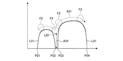
同様に、所定の曲率以上で内側に屈曲する輪郭部分を閉領域の境界が含むと、この輪郭部分を異常部として誤検出する場合があった。図7は、閉領域の他の例を示す模式図であり、輪郭部分等である所定の曲率以上で内側に屈曲するエッジEL2を境界に含むように作成された閉領域を示している。また、図8は、横軸を図7中に一点鎖線で示すライン(エッジEL2の屈曲部分を跨ぐライン)上の境界画素P21,P24間の画素位置とし、縦軸を閉領域の内部である境界画素P21,P22間および境界画素P23,P24間の各画素の画素値として画素値の変化曲線L21を示したものである。エッジEL2の屈曲部分を跨ぐライン上では、図8に示すように、その画素値の変化が屈曲位置で途切れる。ここで、境界が内側に大きく屈曲するエッジEL2を含む閉領域に対してモルフォロジ処理(クロージング処理)を行い、構造要素F2を上側から外接させて移動させた際(矢印A21)、前述の途切れた部分の間隔に対して構造要素F2が大きいとこの部分に構造要素F2が入り込まないため、図8中に一点鎖線で示すような軌跡L22(実際には面)が得られる。このように、閉領域の境界が輪郭部分等である内側に大きく屈曲するエッジを含むと、閉領域の内部に溝位置等であるエッジを含む場合と同様に、構造要素の形状に依存して推定される基準色が実際の画素値から大きく逸脱してしまい、矢印A22で示す差分によって輪郭部分が異常部として誤検出されてしまう場合がある。 Similarly, if the boundary of the closed region includes a contour portion that is bent inward with a predetermined curvature or more, this contour portion may be erroneously detected as an abnormal portion. FIG. 7 is a schematic diagram showing another example of the closed region, and shows the closed region created so as to include an edge EL2 bent inward at a predetermined curvature or more which is a contour portion or the like at the boundary. In FIG. 8, the horizontal axis is the pixel position between the boundary pixels P21 and P24 on the line indicated by the alternate long and short dash line in FIG. 7 (the line straddling the bent portion of the edge EL2), and the vertical axis is the inside of the closed region. A change curve L21 of the pixel value is shown as the pixel value of each pixel between the boundary pixels P21 and P22 and between the boundary pixels P23 and P24. On the line straddling the bent portion of the edge EL2, the change in the pixel value is interrupted at the bent position as shown in FIG. Here, when the morphological process (closing process) is performed on the closed region including the edge EL2 whose boundary is largely bent inward, the structural element F2 is circumscribed and moved from above (arrow A21), the above-mentioned interruption occurs. If the structural element F2 is larger than the interval between the parts, the structural element F2 does not enter the part, so that a locus L22 (actually a surface) as shown by a one-dot chain line in FIG. 8 is obtained. In this way, if the boundary of the closed region includes an edge that bends inwardly, which is a contour portion, etc., it depends on the shape of the structural element, as in the case where the edge of the groove region is included inside the closed region. The estimated reference color may deviate greatly from the actual pixel value, and the contour portion may be erroneously detected as an abnormal portion due to the difference indicated by the arrow A22.
以上のような事態を抑制するため、閉領域作成部17は、勾配強度が所定の値以上である画素(エッジ部分の画素)を領域の内部に含まず、かつ、領域の境界が内側に所定の曲率以上で屈曲しないことを条件として閉領域を作成する。これにより、モルフォロジ処理を適用して行う後段の異常部検出において、基準色を適正に推定することが可能となる。
In order to suppress the above situation, the closed
図9は、実施の形態1の画像処理装置1が行う処理手順を示す全体フローチャートである。なお、ここで説明する処理は、記録部14に記録された画像処理プログラム141に従って画像処理装置1の各部が動作することによって実現される。
FIG. 9 is an overall flowchart illustrating a processing procedure performed by the
図9に示すように、先ず、制御部20が画像取得処理を実行し、処理対象の管腔内画像を取得する(ステップa1)。ここでの処理により、管腔内画像の画像データが外部I/F部11を介して取得され、記録部14に記録される。このようにして取得された後は、この管腔内画像の画像データは、演算部15等の各部によって読み込み可能な状態となる。なお、以下では、取得した管腔内画像の左上を基準にして横方向の座標をxとし、縦方向の座標をyとして、この管腔内画像を構成する各画素の画素値を(x,y)と表記する。
As shown in FIG. 9, first, the
続いて、演算部15において、勾配情報算出部16の特定波長画像抽出部161がR成分画像取得処理を実行し、ステップa1で取得した管腔内画像からR(赤)成分の画像を特定波長成分画像として抽出する(ステップa3)。
Subsequently, in the
管腔内画像に映る血管や出血部位等の構成成分であるヘモグロビンは、短波長帯の光を多く吸光する特性を持つ。図10は、ヘモグロビンの分光吸収特性を示す図であり、横軸を波長λとして酸化ヘモグロビンHbO2の変化曲線を実線で示し、還元ヘモグロビンHbの変化曲線を一点鎖線で示している。このようなヘモグロビンの短波長帯での吸光特性のため、波長成分の多くが短波長帯で構成されるG(緑)成分やB(青)成分は、ヘモグロビンの吸光によって輝度値が下がる。一方、波長成分の多くが長波長帯で構成されるR(赤)成分は、吸光が少なく、ほとんどの光を反射するため、このR(赤)成分からは、生体組織の表面構造を最も反映した情報を得ることができる。そこで、実施の形態1では、生体組織の表面構造によって形成される生体組織の輪郭を得るために、R(赤)成分を特定波長成分とし、R(赤)成分の画像(各画素の画素値をR(赤)成分の値とした画像)を特定波長成分画像として抽出する。 Hemoglobin, which is a structural component such as blood vessels and bleeding sites reflected in intraluminal images, has a characteristic of absorbing a large amount of light in the short wavelength band. FIG. 10 is a diagram showing the spectral absorption characteristics of hemoglobin. The change curve of oxygenated hemoglobin HbO 2 is shown by a solid line and the change curve of reduced hemoglobin Hb is shown by an alternate long and short dash line with the wavelength λ on the horizontal axis. Due to the light absorption characteristics of hemoglobin in the short wavelength band, the luminance value of the G (green) component and B (blue) component, in which most of the wavelength components are configured in the short wavelength band, decreases due to the absorption of hemoglobin. On the other hand, the R (red) component, in which most of the wavelength components are composed of a long wavelength band, has little light absorption and reflects most of the light. Therefore, the R (red) component reflects the surface structure of living tissue most Information can be obtained. Therefore, in the first embodiment, in order to obtain the contour of the living tissue formed by the surface structure of the living tissue, the R (red) component is a specific wavelength component, and the R (red) component image (pixel value of each pixel) (Image with R (red) component value) as a specific wavelength component image.
続いて、輪郭抽出処理に移る(ステップa5)。この輪郭抽出処理では、特定波長成分画像から線エッジを検出し、検出した線エッジを生体組織の輪郭として抽出する。図11は、輪郭抽出処理の詳細な処理手順を示すフローチャートである。 Subsequently, the process proceeds to contour extraction processing (step a5). In this contour extraction process, a line edge is detected from the specific wavelength component image, and the detected line edge is extracted as a contour of the living tissue. FIG. 11 is a flowchart showing a detailed processing procedure of the contour extraction processing.
図11に示すように、輪郭抽出処理では、先ず、勾配情報算出部16の勾配強度算出部162が勾配強度算出処理を実行し、特定波長成分画像の勾配強度を算出する(ステップb1)。例えば、特定波長成分画像に対し、ノイズを低減する平滑化処理と微分処理とを同時に行うフィルタ処理として既に公知であるsobel処理(参考:CG−ARTS協会,ディジタル画像処理,116P−ソーベルフィルタ)を行って画素毎に勾配強度を算出する。ただし、適用可能な処理はsobel処理に限定されるものではなく、平滑化処理と微分処理とを組み合わせたフィルタであれば他のフィルタを用いて行うこととしてもよい。
As shown in FIG. 11, in the contour extraction process, first, the
続いて、閉領域作成部17において、分割部171の線エッジ検出部172が線エッジ検出処理を実行し、勾配強度をもとに特定波長成分画像内の線エッジを検出する(ステップb3)。例えば、線エッジは、勾配強度をもとに勾配の最大位置を検出し、検出した勾配の最大位置に対して閾値処理を行うことで検出する。閾値処理で用いる閾値は、固定値としてもよいし、操作部12を介したユーザ操作等によって設定変更可能に構成してもよい。そして、次式(1),(2)に従い、検出した線エッジの画素に「1」、線エッジ以外の画素に「0」をそれぞれ割り当てて輪郭画像として得る。
線エッジ上の画素の場合、H(x,y)=1 ・・・(1)
線エッジ上以外の画素の場合、H(x,y)=0 ・・・(2)
Subsequently, in the closed
In the case of a pixel on a line edge, H (x, y) = 1 (1)
In the case of a pixel other than on the line edge, H (x, y) = 0 (2)
ここで、以上説明した輪郭抽出処理で勾配強度算出部162が行うステップb1の処理および線エッジ検出部172が行うステップb3の処理を具体的に実現するアルゴリズムとしては、既に公知のケニーのエッジ検出アルゴリズム(Canny edge detector/参考:CG−ARTS協会,ディジタル画像処理,209P−輪郭線検出)を用いることができる。以上のようにして輪郭抽出処理を行ったならば、図9のステップa5にリターンし、その後ステップa7に移行する。
Here, as an algorithm that specifically realizes the process of step b1 performed by the gradient
ステップa7では、基点検出部173が基点検出処理を実行し、線エッジをもとに分割線を引くための基点を検出する。実施の形態1では、端点または屈曲点の周囲(例えば8近傍画素)における線エッジの存在パターン(以下、「基点パターン」と呼ぶ。)を予め定義しておく。図12−1〜図12−8および図13−1〜図13−8は、それぞれ基点パターンを示しており、図12−1〜図12−8および図13−1〜図13−8の各図に示す8種類の基点パターンが端点の基点パターンに対応し、図13−1〜図13−8の各図に示す8種類の基点パターンが端点または屈曲点の基点パターンに対応している。ここで、中央の画素の8近傍画素を識別するため、各図中において8近傍画素の各マス目に示すように、それぞれの座標を左上から右周りにa,b,c,d,e,f,g,hとする。なお、各図中において、ハッチングを付したマス目が線エッジの画素を表している。そして、図9のステップa7の処理として、基点検出部173は、線エッジ上の各画素を順次注目画素とし、その8近傍画素における線エッジの存在パターンが図12−1〜図12−8および図13−1〜図13−8の各図に示す基点パターンと一致するか否かを判定する。そして、基点検出部173は、一致すると判定した線エッジ上の画素を端点または屈曲点として検出する。
In step a7, the base
実際には、基点検出部173は、輪郭画像をもとに、次式(3),(4)に従ってH(x,y)=1の画素の8近傍画素が基点パターンと一致するか否かの判定を行い、端点または屈曲点を検出する。

ここで、式(3),(4)において、条件1を満たすか否かが図12−1〜図12−8の各基点パターンと一致するか否かの判定に相当する。すなわち、図12−1〜図12−8の各基点パターンは、8近傍画素のうちのいずれか1つが線エッジの画素であるため、8近傍画素の画素値の合計が「1」であることを条件1としている。また、条件2を満たすか否かが図13−1〜図13−8の各基点パターンと一致するか否かの判定に相当する。すなわち、図13−1〜図13−8の各基点パターンは、8近傍画素のうちの隣接する2つの画素が線エッジの画素であるため、8近傍画素の画素値の合計が「2」であり、かつ、隣接する2画素の画素値を乗算した値の合計が「1」であることを条件2としている。
Here, in the formulas (3) and (4), whether or not the
そして、基点検出部173は、式(3)に従い、線エッジ上のH(x,y)=1の画素のうち、条件1を満たす端点および条件2を満たす端点または屈曲点の画素についてH(x,y)=2とすることで、分割線の基点として設定する。また、基点検出部173は、式(4)に従い、線エッジ上のH(x,y)=1の画素のうち、条件1を満たさず、条件2も満たさない画素については、H(x,y)=1のままとする。なお、ここでは式(3),(4)に従って端点または屈曲点を検出することとしたが、検出の方法はこれに限定されるものではない。例えば、マッチング法を用いて端点または屈曲点を検出することとしてもよく、例えば図12−1〜図12−8および図13−1〜図13−8の各基点パターンによって定まる線エッジの端点および所定の値以上の曲率で屈曲する屈曲点を検出できれば適宜別の方法を採用することとしてよい。
Then, the base
続いて、図9に示すように、分割ラベリング処理に移る(ステップa9)。この分割ラベリング処理では、先ず、分割線作成部174が、基点として設定されたH(x,y)=2の画素をもとに、線エッジ上の画素であるH(x,y)=1の画素との交点まで分割線を引く。H(x,y)=1の画素と交差しない場合は、画像の縁まで分割線を引く。実施の形態1では、一例として分割線を水平方向および垂直方向に沿ってそれぞれ引く構成を示す。なお、分割線を引く方向は水平方向や垂直方向に限定されるものではなく、異なる2つ以上の方向に引く構成であれば、方向は適宜設定してよい。
Subsequently, as shown in FIG. 9, the process proceeds to a division labeling process (step a9). In this division labeling process, first, the division
ここで、分割ラベリング処理について、図14〜図16を参照して説明する。図14は、管腔内画像の一例を示す図である。また、図15は、図14の管腔内画像を処理することで検出した線エッジの一部およびこの一部の線エッジの基点を示す図であり、7個の基点P31〜P37を示している。そして、図16は、図15に示す線エッジおよび基点をもとに引いた分割線を示す模式図である。 Here, the division labeling process will be described with reference to FIGS. FIG. 14 is a diagram illustrating an example of the intraluminal image. FIG. 15 is a diagram showing a part of the line edges detected by processing the intraluminal image of FIG. 14 and the base points of the part of the line edges, and shows seven base points P31 to P37. Yes. FIG. 16 is a schematic diagram showing a dividing line drawn based on the line edge and the base point shown in FIG.
例えば、図16において、基点P33に着目すると、分割線作成部174は、基点P33を通る水平方向の直線であって、線エッジとの交点P331,P332を端点とする直線である分割線L331を引き、さらに、基点P33を通る垂直方向の直線であって、線エッジとの交点P333,P334を端点とする直線である分割線L332を引く。また、基点P37に着目すれば、分割線作成部174は、基点P37を通る水平方向の直線であって、線エッジとの交点P371と画像の縁P372とを端点とする直線である分割線L371を引き、さらに、基点P37を通る垂直方向の直線であって、線エッジとの交点P373,P374を端点とする直線である分割線L372を引く。
For example, in FIG. 16, paying attention to the base point P33, the parting
その後、分割部171が、線エッジ検出部172が検出した線エッジと分割線作成部174が引いた分割線とをもとに、管腔内画像を線エッジと分割線とで囲まれた領域である複数の領域に分割する。これは、線エッジと分割線とで囲まれた1つの領域内の画素に同一のラベルを付与することで実現できる。ここでは、分割された領域は複数存在するため、各領域にそれぞれ固有のラベル番号を割り振る。そして、例えば、各画素の画素値をその画素が属する領域のラベル番号とした分割画像を得る。なお、ラベル番号を付与する方法としては、例えば、既に公知のラベリング処理(参考:CG−ARTS協会,ディジタル画像処理,181P−ラベリング)が挙げられる。
Thereafter, the dividing
続いて、図9に示すように、統合部175が領域統合処理を実行する(ステップa11)。この領域統合処理では、統合部175は、分割画像を参照して複数の領域それぞれについて領域情報を算出し、算出した領域情報をもとに領域を統合する。図17は、領域統合処理の詳細な処理手順を示すフローチャートである。
Subsequently, as shown in FIG. 9, the
図17に示すように、領域統合処理では、先ず領域情報算出部176が領域情報算出処理を実行する(ステップc1)。例えば、領域情報算出部176は、複数の領域に対して公知の処理である粒子解析を行うことで各領域の特徴量を算出する。ここでは、例えば、各領域それぞれの水平フェレ径、垂直フェレ径、および面積を粒子解析の特徴量として算出する。また、領域情報算出部176は、隣接する領域との境界の長さを算出する。例えば、各領域を順次注目領域として1つずつ処理し、隣接する領域との境界を形成している分割線を特定する。そして、特定した分割線の長さを隣接する領域との境界の長さとして算出する。注目領域の境界を形成している分割線が複数存在する場合には、分割線毎に隣接する領域との境界の長さを算出する。そして、領域情報算出部176は、粒子解析の特徴量、隣接する領域との境界の長さ、およびその領域の位置を領域情報とし、この領域情報を領域毎に算出する。
As shown in FIG. 17, in the region integration process, the region
続いて、領域統合部177が統合処理を実行し、領域情報をもとに、分割された複数の領域を統合する(ステップc3)。その後、領域統合部177は、修正処理を行い、統合した領域を修正する(ステップc5)。
Subsequently, the
上記したように、領域統合部177は、勾配強度が所定の値以上である画素を統合した領域内部に含まず、かつ、統合した領域の境界がこの領域の内側に所定の曲率以上で屈曲しないことを条件として領域の統合を行う。ここで、勾配強度が所定の値以上である画素を統合した領域内部に含まないことを「第1の領域条件」と呼び、統合した領域の境界がこの領域の内側に所定の曲率以上で屈曲しないことを「第2の領域条件」と呼ぶ。実施の形態1では、図11のステップb3で説明したように勾配強度を閾値処理することでエッジ線(すなわち勾配強度が所定の値以上である画素)を検出し、図9のステップa7で説明したように線エッジが予め設定される所定の値以上の曲率で屈曲する屈曲点を(実際には、この屈曲点とエッジの端点とを)基点として検出している。そこで、統合後の領域の内部にこれら基点を含む線エッジが存在しないように領域同士を統合することによって、第1,第2の領域条件を満足する統合を行う。例えば、実施の形態1では、各基点を通る水平方向および垂直方向に沿った分割線を少なくとも1本は残す統合を行うことでこれを実現する。
As described above, the
図18は、領域の統合原理を説明する説明図であり、図16の分割線で区画された複数の領域のうちの2つE41,E42を統合する様子を示している。図19は、図16の各領域の統合結果を示す模式図である。また、図20は、統合結果を示す他の模式図である。例えば、図18(a)中にハッチングを付して示す1つの領域E41に着目すると、この領域E41の境界を構成している分割線はL41〜L44の4本であり、L41,L43の長さがL42,L44よりも長い。そして、この長い方の分割線L41を挟んで領域E41と隣接している領域E42は、分割線L43を挟んで領域E41と隣接している領域E43よりも面積が小さい。そこで、先ず、領域E41と領域E42とを統合する。この結果、これら2つの領域E41,E42は、図18(b)に示すように、1つの領域E44となる。ステップc3では、このような領域の統合を繰り返し行い、閉領域を作成する。 FIG. 18 is an explanatory diagram for explaining the region integration principle, and shows a state in which two of the plurality of regions E41 and E42 divided by the dividing line in FIG. 16 are integrated. FIG. 19 is a schematic diagram showing the integration result of each region in FIG. FIG. 20 is another schematic diagram showing the integration result. For example, when attention is paid to one area E41 indicated by hatching in FIG. 18A, the dividing lines constituting the boundary of the area E41 are four lines L41 to L44, and the lengths of L41 and L43 are long. Is longer than L42 and L44. The area E42 adjacent to the area E41 across the longer dividing line L41 has a smaller area than the area E43 adjacent to the area E41 across the dividing line L43. Therefore, first, the area E41 and the area E42 are integrated. As a result, these two regions E41 and E42 become one region E44 as shown in FIG. In step c3, such region integration is repeatedly performed to create a closed region.
より詳細には、領域同士を統合する際、前述のように各基点を通る水平方向および垂直方向に沿った分割線を少なくとも1本は残す統合を行う。例えば、図19において、分割線L51によって区画される領域E51,E52を統合し、統合した領域をさらに分割線L52によって区画される領域E53と統合したとする。この場合、基点P33からの分割線は1本も残らないこととなる。このような統合をすると、領域E51,E52,E53が1つの領域となり、この領域の内部に端点である基点P33を含む図19中に破線EL5で囲ったエッジが含まれることとなる。この破線EL5で囲ったエッジ上の各点は、勾配強度が所定の値以上である画素であり、第1の領域条件を満たさない。したがって、このような統合は行わない。 More specifically, when the regions are integrated, as described above, the integration is performed so that at least one parting line along the horizontal direction and the vertical direction passing through each base point is left. For example, in FIG. 19, it is assumed that the areas E51 and E52 defined by the dividing line L51 are integrated, and the integrated area is further integrated with the area E53 defined by the dividing line L52. In this case, no dividing line from the base point P33 remains. When such integration is performed, the areas E51, E52, and E53 become one area, and the edge surrounded by the broken line EL5 is included in this area including the base point P33 that is the end point. Each point on the edge surrounded by the broken line EL5 is a pixel whose gradient strength is a predetermined value or more, and does not satisfy the first region condition. Therefore, such integration is not performed.
また、図20の例では、エッジEL6が内側に所定の曲率以上で屈曲した屈曲点である基点P6を含んでおり、このエッジEL6と分割線L6とで囲まれた(エッジEL6および分割線L6によって区画された)3つの領域E61,E62,E63を示している。ここで、分割線L6を挟んで隣接する領域E61,E62を統合したとする。この場合、基点P6からの分割線は1本も残らないこととなる。このような統合をすると、領域E61,E62は1つの領域となり、この領域の境界が屈曲点である基点P6を含むため、第2の領域条件を満たさない。したがって、このような統合は行わない。 In the example of FIG. 20, the edge EL6 includes a base point P6 that is a bent point that is bent inward with a predetermined curvature or more, and is surrounded by the edge EL6 and the dividing line L6 (the edge EL6 and the dividing line L6). Three regions E61, E62, E63 are shown. Here, it is assumed that the regions E61 and E62 adjacent to each other across the dividing line L6 are integrated. In this case, no dividing line from the base point P6 remains. When such integration is performed, the regions E61 and E62 become one region, and the boundary of these regions includes the base point P6 that is a bending point, and thus the second region condition is not satisfied. Therefore, such integration is not performed.
実際の統合処理では、領域統合部177は、先ず、ステップc3の処理として、細長い領域を減らすため、領域情報をもとに各領域の水平フェレ径と垂直フェレ径との比を算出し、算出した比が大きい領域を統合対象として選択する。続いて、領域統合部177は、統合対象とした領域の領域情報の隣接する領域との境界の長さをもとに、その境界を構成している分割線の中から長いものを2本選択する。その後、領域統合部177は、選択した分割線を挟んで隣接している領域から面積の小さい方を選んで統合対象の領域と統合する。
In the actual integration process, the
その後、領域統合部177は、ステップc5の処理として、分割線が1本も残っていない基点の有無を判定する。そして、領域統合部177は、該当する基点がある場合には、ステップc3で統合された領域を分割して元に戻し(統合した領域間に再度分割線を引き)、領域を修正する。なお、領域統合部177は、ステップc3およびステップc5で統合・修正の結果を反映させて分割画像を更新する。なお、この修正処理を実現するため、領域統合部177は、ステップc3での統合前の領域の情報を保持しておく必要がある。
Thereafter, the
続いて、統合制御部178が、統合対象の領域の有無を判定する。そして、統合対象の領域がある場合には(ステップc7:Yes)、ステップc1に戻って上記した処理を繰り返す。一方、統合対象の領域がない場合には(ステップc7:No)、この時点で残っている領域(この時点で分割画像中において異なるラベルが付与されている領域)を閉領域とし、図9のステップa11にリターンする。そしてその後、ステップa13に移行する。
Subsequently, the
そして、ステップa11では、異常部検出部18が異常部検出処理を実行する。例えば、各閉領域を順次注目閉領域とし、注目閉領域の内部の異常部を検出することで閉領域毎に内部の異常部を検出する。具体的には、先ず、基準色推定部181が、管腔内画像における注目閉領域の画素値をもとに正常な生体組織を示す基準色を推定する。続いて、異常色部検出部182が、注目閉領域について推定した基準色をもとに、注目閉領域の内部において色特徴量(例えば画素値)が前述の基準色から所定の値以上外れた外れ値である領域を異常色部として検出する。
In step a11, the abnormal
ここでの処理は、例えば、注目閉領域に対してモルフォロジフィルタを用いたモルフォロジ処理の一例である既に公知のトップハット処理またはブラックハット(black-hat/ボトムハットともいう。)処理を行うことで実現できる。ここで、トップハット処理は、管腔内画像の画素値に対してオープニング処理を行い、得られた画像と、元の管腔内画像の画素値との差分値を閾値処理することで異常色部を検出する方法である。一方のブラックハット処理は、管腔内画像の画素値に対して既に公知であるクロージング処理を行い、得られた画像と、元の管腔内画像の画素値との差分値を閾値処理することで異常色部を検出する方法である。ステップa11では、このトップハット処理またはブラックハット処理を閉領域毎に行うことで各閉領域の内部から異常色部を検出し、検出した異常色部を病変等の異常部とする。 The processing here is, for example, by performing already known top hat processing or black hat processing (also referred to as black-hat / bottom hat processing), which is an example of morphology processing using a morphology filter for the target closed region. realizable. Here, the top hat process performs an opening process on the pixel value of the intraluminal image, and performs threshold processing on the difference value between the obtained image and the pixel value of the original intraluminal image. This is a method for detecting a part. On the other hand, the black hat process performs a known closing process on the pixel value of the intraluminal image, and thresholds the difference value between the obtained image and the pixel value of the original intraluminal image. In this method, an abnormal color portion is detected. In step a11, this top hat processing or black hat processing is performed for each closed region, thereby detecting an abnormal color portion from the inside of each closed region, and setting the detected abnormal color portion as an abnormal portion such as a lesion.
処理手順としては、先ず、各閉領域に対し、個別に所定サイズの球形の構造要素を用いた3次元モルフォロジ処理(濃淡モルフォロジ)を行って基準色を推定する。続いて、閉領域毎に、内部の画素値と該当する閉領域について推定した基準色との差分値を算出する。その後、算出した差分値を閾値処理し、差分値が予め設定される所定の閾値以上である画素を異常色部の画素として検出する。以上のようにして行うステップa11での異常部の検出結果は表示部13に出力され、例えば管腔内画像中で異常部の領域を他の領域と識別可能に表して表示するといったことが行われて医師等のユーザに提示される。
As a processing procedure, first, a reference color is estimated by performing three-dimensional morphology processing (shading morphology) using spherical structural elements of a predetermined size individually for each closed region. Subsequently, for each closed region, a difference value between the internal pixel value and the reference color estimated for the corresponding closed region is calculated. Thereafter, the calculated difference value is subjected to threshold processing, and pixels whose difference value is equal to or greater than a predetermined threshold value are detected as pixels in the abnormal color portion. The abnormal part detection result in step a11 performed as described above is output to the
以上説明したように、実施の形態1では、画素毎に勾配強度を算出し、各画素の勾配強度をもとにエッジ線を検出することとした。また、エッジ線の端点および屈曲点を検出して基点とし、この基点を通る例えば水平方向および垂直方向に沿った分割線を引くことで管腔内画像を複数の領域に分割することとした。そして、勾配強度が所定の値以上である画素を統合した領域内部に含まず、かつ、統合した領域の境界がこの領域の内側に所定の曲率以上で屈曲しないことを条件として分割した領域を統合することで閉領域を作成し、作成した閉領域毎に異常部を検出することとした。上記したように、管腔内画像には、生体組織が形成する溝位置や輪郭部分が映り、この溝位置や輪郭部分は、管腔内画像中で勾配強度が所定の値以上である部分や、輪郭がある程度の曲率で屈曲する部分として現れる。したがって、管腔内画像中に映る溝位置や輪郭部分を内部や境界に含まないように閉領域を作成することができ、閉領域毎にモルフォロジ処理を適用することで閉領域内部の異常部を検出することができる。これによれば、溝位置や輪郭部分を異常部として誤検出することなく管腔内画像から異常部を精度良く検出することができる。 As described above, in the first embodiment, the gradient intensity is calculated for each pixel, and the edge line is detected based on the gradient intensity of each pixel. Further, the end point and the bending point of the edge line are detected and used as a base point, and the intraluminal image is divided into a plurality of regions by drawing, for example, dividing lines along the horizontal direction and the vertical direction passing through the base point. Then, the regions divided by the condition that the boundary of the integrated region is not included in the integrated region and the boundary of the integrated region does not bend more than the predetermined curvature is integrated within the integrated region. Thus, a closed region is created, and an abnormal part is detected for each created closed region. As described above, the intraluminal image shows the groove position and contour portion formed by the living tissue, and this groove position and contour portion is a portion where the gradient intensity in the intraluminal image is a predetermined value or more. The contour appears as a bent part with a certain degree of curvature. Therefore, it is possible to create a closed region so that the groove position and contour portion reflected in the intraluminal image are not included in the inside or the boundary, and by applying morphological processing to each closed region, the abnormal portion inside the closed region can be removed. Can be detected. According to this, an abnormal part can be accurately detected from the intraluminal image without erroneously detecting the groove position or the contour part as an abnormal part.
(実施の形態2)
次に、実施の形態2について説明する。図21は、実施の形態2の画像処理装置1bの機能構成を説明するブロック図である。なお、図21において、実施の形態1で説明した構成と同一の構成については、同一の符号を付する。また、図22は、演算部15bを構成する閉領域作成部19bの構成例を説明するブロック図である。図21に示すように、画像処理装置1bは、外部I/F部11と、操作部12と、表示部13と、記録部14bと、演算部15bと、画像処理装置1b全体の動作を制御する制御部20とを備える。
(Embodiment 2)
Next, a second embodiment will be described. FIG. 21 is a block diagram illustrating a functional configuration of the
記録部14bには、管腔内画像から異常部を検出するための画像処理プログラム141bが記録される。
The
また、演算部15bは、勾配情報算出手段としての勾配情報算出部16と、閉領域作成手段としての閉領域作成部19bと、異常部検出手段としての異常部検出部18とを含み、これら勾配情報算出部16、閉領域作成部19bおよび異常部検出部18は、この順に接続されている。実施の形態2の画像処理装置1bは、演算部15bが備える閉領域作成部19bが実施の形態1の画像処理装置1と異なる。ここで、実施の形態2においても、閉領域作成部19bは、勾配強度が予め設定される所定の値以上である画素を領域の内部に含まず(第1の領域条件)、かつ、領域の境界がこの領域の内側に所定の曲率以上で屈曲しないこと(第2の領域条件)を条件とし、条件を満たす閉領域を作成するが、その構成が実施の形態1と異なる。すなわち、閉領域作成部19bは、図22に示すように、初期閉領域作成手段としての初期閉領域作成部191と、第1のエネルギー算出手段としての第1のエネルギー算出部192と、閉領域更新手段としての閉領域更新部193とを備え、これら初期閉領域作成部191、第1のエネルギー算出部192および閉領域更新部193は、この順に接続されている。
The
初期閉領域作成部191は、勾配情報算出部16から入力される勾配強度をもとに、周囲と比較して相対的に勾配強度が小さい位置に閉領域の初期形状(初期閉領域)を作成する。作成された閉領域の初期形状は、第1のエネルギー算出部192に出力される。
The initial closed
第1のエネルギー算出部192は、入力される閉領域の初期形状について、閉領域の境界の滑らかさを表し、閉領域の境界が滑らかなほど小さい値を返す内部エネルギーと、閉領域の境界における勾配強度が大きいほど小さい値を返す画像エネルギーと、閉領域の大きさが大きいほど小さい値を返す外部エネルギーとの加重和を第1のエネルギーとして算出する。なお、本例では、内部エネルギー、画像エネルギーおよび外部エネルギーの加重和を算出することとするが、必ずしも3つの加重和を算出する必要はなく、これらのうちのいずれか2つの加重和を算出することとしてもよい。算出された第1のエネルギーは、入力された閉領域の初期形状とともに閉領域更新部193に出力される。
The first
閉領域更新部193は、第1のエネルギーが小さくなる方向へ閉領域の形状を更新する。この閉領域更新部193は、更新手段としての更新部194と、第2のエネルギー算出手段としての第2のエネルギー算出部195と、修正手段としての修正部196と、閉領域更新制御手段としての閉領域更新制御部197とを備える。ここで、更新部194、第2のエネルギー算出部195および修正部196はこの順に接続され、修正部196は、更新部194および閉領域更新制御部197に接続されている。また、更新部194、第2のエネルギー算出部195および修正部196には閉領域更新制御部197からの制御信号が入力されるようになっており、閉領域更新制御部197は、更新部194、第2のエネルギー算出部195および修正部196の動作を制御する。
The closed
更新部194は、閉領域の形状を更新する。具体的には、更新部194は、初回の処理では、第1のエネルギー算出部192から入力される閉領域の初期形状を更新する。また、この更新部194には、修正部196から更新・修正後の閉領域の形状が入力されるようになっており、2回目以降の処理では、この更新・修正後の閉領域の形状を更新する。更新された閉領域の形状は、第2のエネルギー算出部195に出力される。
The updating
第2のエネルギー算出部195は、入力される閉領域の形状をもとに、閉領域の境界が滑らかなほど小さい値を返す内部エネルギーと、閉領域の境界における勾配強度が大きいほど小さい値を返す画像エネルギーと、閉領域の大きさが大きいほど小さい値を返す外部エネルギーとの加重和を第2のエネルギーとして算出する。この第2のエネルギーを算出する場合も、第1のエネルギーと同様に、内部エネルギー、画像エネルギーおよび外部エネルギーのうちの少なくとも2つの加重和を算出することとしてもよい。算出された第2のエネルギーは、入力された閉領域の形状とともに修正部196に出力される。
Based on the shape of the input closed region, the second
修正部196は、入力される第2のエネルギーを第1のエネルギーと比較し、第1のエネルギーの方が小さい場合には、入力された閉領域の形状を更新部194による更新前の形状へ修正する。一方、第2のエネルギーの方が小さい場合には、修正部196は、第1のエネルギーを第2のエネルギーで更新する。そして、修正部196は、修正後の閉領域の形状を更新部194に出力する。また、修正部196は、入力された第2のエネルギーが第1のエネルギーより大きく、第1のエネルギーが予め設定される所定回数変化しなくなった場合には、その旨の通知を閉領域更新制御部197に出力する。
The
閉領域更新制御部197は、更新部が閉領域の形状を更新し、第2のエネルギー算出部195が第2のエネルギーを算出し、修正部196が閉領域の形状を修正する処理の繰り返しを制御する。そして、閉領域更新制御部197は、修正部196から第1のエネルギーが変化しなくなった旨の通知が入力された時点で、更新部194、第2のエネルギー算出部195および修正部196による処理の繰り返しを終了する。
The closed region
以上のように、閉領域作成部19bは、管腔内画像中の勾配強度が小さい領域に閉領域の初期形状を作成し、閉領域の形状によって定まる第1のエネルギーが小さくなる方向へ閉領域の形状を更新・修正していく。そして、閉領域作成部19bは、更新・修正後の閉領域の位置を特定する情報を異常部検出部18に出力する。
As described above, the closed
図23は、実施の形態2の画像処理装置1bが行う処理手順を示す全体フローチャートである。なお、ここで説明する処理は、記録部14bに記録された画像処理プログラム141bに従って画像処理装置1bの各部が動作することによって実現される。また、図23において、実施の形態1と同一の処理工程には、同一の符号を付する。
FIG. 23 is an overall flowchart illustrating a processing procedure performed by the
図23に示すように、実施の形態2では、ステップa3でR成分画像取得処理を実行した後、勾配情報算出部16において勾配強度算出部が勾配強度算出処理を実行し、特定波長成分画像の勾配強度を算出する(ステップd5)。例えば、図11のステップb1と同様に特定波長成分画像に対してSobel処理を行い、勾配強度を算出する。なお、勾配強度の算出方法はこれに限定されるものではなく、Sobel処理以外の微分フィルタを用いて勾配強度を算出することとしてもよい。
As shown in FIG. 23, in the second embodiment, after the R component image acquisition process is executed in step a3, the gradient intensity calculation unit executes the gradient intensity calculation process in the gradient
続いて、閉領域作成部19bが閉領域作成処理を実行し、既に公知の動的輪郭法を用いて閉領域を作成する(ステップd7)。この閉領域作成処理は、実際には、例えば画像内の全域に閉領域が作成されるまで複数回繰り返し行い、複数の閉領域を作成する。図24は、閉領域作成処理の詳細な処理手順を示すフローチャートである。
Subsequently, the closed
図24に示すように、閉領域作成処理では、先ず、初期閉領域作成部191が初期閉領域作成処理を実行し、勾配強度をもとに、周囲と比較して相対的に勾配強度が小さい範囲に閉領域の初期形状(初期閉領域)を作成する(ステップe1)。上記したように、生体組織が形成する溝位置や輪郭部分は管腔内画像において勾配強度が所定の値以上である部分として表れる。そこで、初期閉領域作成部191は、このような部分を含まないように、勾配強度が小さい箇所に閉領域の初期形状(初期閉領域)を作成する。
As shown in FIG. 24, in the closed region creating process, first, the initial closed
具体的には、先ず、勾配強度が最小の画素を選択する。そして、選択した画素を含む所定サイズの範囲の勾配強度を比較し、選択した画素周囲の勾配強度が小さい範囲を特定することで初期閉領域を作成する。また、2回目以降の閉領域作成処理においてステップe1の処理を実行し、初期閉領域を作成する際には、作成済みの閉領域(他の閉領域)外において勾配強度が最小の画素を選択し、他の閉領域と重ならないように初期閉領域を作成する。あるいは、初期閉領域を作成済みの他の閉領域と一部が重なるように作成し、他の閉領域に一部が重なるように初期閉領域を作成することがエネルギー的に適切でない場合(例えば、他の閉領域に一部が重なるように初期閉領域を作成すると第1のエネルギーが所定の閾値を超える場合)には、他の閉領域と重ならないように初期閉領域を作成することとしてもよい。この場合には、先ず、他の閉領域と一部が重なるように初期閉領域を作成する。続いて、作成した初期閉領域について後段のステップe3と同様の要領で第1のエネルギーを算出する。そして、算出した第1のエネルギーの値を閾値処理し、予め設定される所定の閾値を超える場合に、作成した初期閉領域を他の閉領域と重ならないように修正する。 Specifically, first, a pixel having the smallest gradient strength is selected. Then, the gradient strength of a predetermined size range including the selected pixel is compared, and an initial closed region is created by specifying a range having a small gradient strength around the selected pixel. In addition, when the initial closed region is created by executing the process of step e1 in the second and subsequent closed region creation processes, the pixel having the smallest gradient intensity is selected outside the created closed region (other closed regions). The initial closed region is created so as not to overlap with other closed regions. Alternatively, when it is not energetically appropriate to create an initial closed region so that it partially overlaps with another closed region that has been created, and to create an initial closed region so that it partially overlaps other closed regions (for example, If the first energy exceeds a predetermined threshold when the initial closed region is created so as to partially overlap the other closed regions), the initial closed region is created so as not to overlap with the other closed regions. Also good. In this case, first, an initial closed region is created so as to partially overlap other closed regions. Subsequently, the first energy is calculated for the created initial closed region in the same manner as in the subsequent step e3. Then, a threshold value process is performed on the calculated first energy value, and the created initial closed region is corrected so as not to overlap other closed regions when a predetermined threshold value is exceeded.
図25は、閉領域の形状を説明する模式図である。実施の形態2において、ステップe1で作成される閉領域の初期形状(初期閉領域)は、図25に示すように、初期閉領域E7の境界上の画素に配置される複数の制御点Pcを結んだものとして定義される。このとき、境界上の全ての画素を各制御点Pcとしてもよいし、境界上に例えば所定の間隔で配置することとしてもよい。あるいは、中心P7から放射状に設定される方向との交点に設定することとしてもよく、適宜の方法で配置してよい。後段の処理である図24のステップe3〜ステップe9では、初期閉領域E7の境界を形成する各制御点Pcの位置やその位置における勾配強度、中心P7からの各制御点Pcの距離等から上記した第1のエネルギーを算出する。そして、算出した第1のエネルギーが小さくなるように制御点Pcを移動させて初期閉領域E7を更新・修正していき、閉領域を作成する。 FIG. 25 is a schematic diagram illustrating the shape of the closed region. In the second embodiment, the initial shape (initial closed region) of the closed region created in step e1 includes a plurality of control points Pc arranged at pixels on the boundary of the initial closed region E7 as shown in FIG. Defined as connected. At this time, all the pixels on the boundary may be set as the respective control points Pc, or may be arranged on the boundary at a predetermined interval, for example. Or it is good also as setting to the intersection with the direction set radially from the center P7, and you may arrange | position by an appropriate method. In steps e3 to e9 in FIG. 24, which are subsequent processes, the position of each control point Pc that forms the boundary of the initial closed region E7, the gradient strength at that position, the distance of each control point Pc from the center P7, etc. The calculated first energy is calculated. Then, the control point Pc is moved so as to reduce the calculated first energy, and the initial closed region E7 is updated / corrected to create a closed region.
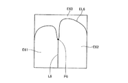
実際の処理では、後述するように、閉領域作成部19bが、初期閉領域を領域が広がる方向に更新・修正していくことで閉領域を作成する。このとき、初期閉領域の外側に存在するエッジが初期閉領域を更新・修正していく過程で閉領域の内部に入り込まないようにすることで、第1の領域条件を満たす閉領域を作成する。また、初期閉領域を更新・修正していく過程で閉領域の境界がその外側に存在する大きく屈曲するエッジに沿って広がってしまい、境界が大きく屈曲してしまうことがないようにすることで、第2の領域条件を満たす閉領域を作成する。図26は、閉領域の一例を示す図であり、輪郭部分等である所定の曲率以上で内側に屈曲する部分P8を含むエッジEL8の内側に作成された2つの閉領域E81,E82を示している。図26に示すように、閉領域E81,E82のそれぞれは、屈曲部分P8に沿って境界が広がらないように作成される。
In actual processing, as will be described later, the closed
先ず、ステップe3では、第1のエネルギー算出部192が第1のエネルギー算出処理を実行し、閉領域の初期形状(初期閉領域)について、閉領域の境界が滑らかなほど小さい値を返す内部エネルギーと、閉領域の境界における勾配強度が大きいほど小さい値を返す画像エネルギーと、閉領域の大きさが大きいほど小さい値を返す外部エネルギーとの加重和を第1のエネルギーとして算出する。
First, in step e3, the first
ここで、上記したように、閉領域の初期形状は、複数の制御点を結んだものとして定義される。そして、第1のエネルギーは、各制御点における内部エネルギー、画像エネルギーおよび外部エネルギーの3つのエネルギーの加重和の総和として算出され、その算出式は次式(5)で表される。
ここで、Nは制御点の個数を表す。また、Einternalは内部エネルギーを表し、Eimageは画像エネルギーを表し、Eexternalは外部エネルギーを表す。以下、順に各エネルギーについて説明する。 Here, N represents the number of control points. E internal represents internal energy, E image represents image energy, and E external represents external energy. Hereinafter, each energy will be described in order.
内部エネルギーEinternalは、注目する制御点v2が、隣接する制御点v1,v3の位置に対して閉領域の内側に所定の曲率以上で屈曲しないように制限するエネルギーであり、第2の領域条件を満たす場合に小さくなるような値として算出される。例えば、内部エネルギーEinternalは、次式(6),(7)に従って、3つの制御点v1,v2,v3間のベクトルxa,xbの外積をもとに算出する。
画像エネルギーEimageは、注目する制御点位置の画素の勾配強度に反比例するエネルギーであり、次式(8)で表され、第1の領域条件を満たす場合に小さくなるような値として算出される。
外部エネルギーEexternalは、注目する制御点が閉領域の広がる方向へ受けるエネルギーであり、閉領域の中心からの注目する制御点の距離に反比例する式である次式(6)に従って算出する。
なお、式(7)のα、式(8)のβおよび式(9)のγは、それぞれ該当するエネルギーに対する重み付け係数を表し、経験則に従って値を決定する。 Note that α in the equation (7), β in the equation (8), and γ in the equation (9) each represent a weighting coefficient for the corresponding energy, and determine a value according to an empirical rule.
続いて、図24に示すように、更新部194が制御点位置更新処理を実行し、閉領域の形状を更新する(ステップe5)。上記した式(6)の外部エネルギーに従うと、閉領域の形状は、広がる方向へ更新する(制御点の位置を閉領域が広がる方向へ移動させる)ことでエネルギーが小さくなる。このため、周囲8方向のうち、閉領域の外側となる方向へ優先して制御点を移動させることで閉領域の形状を更新する。例えば、図25の例では、各制御点Pcの位置を初期閉領域E7の境界外側に移動させ、その形状を例えば図25中に破線で示すように広がる方向へ更新する。各制御点を移動させる距離については、例えば乱数を発生させる等して決定する。
Subsequently, as illustrated in FIG. 24, the
続いて、第2のエネルギー算出部195が第2のエネルギー算出処理を実行し、更新後の閉領域の形状について、閉領域の境界が滑らかなほど小さい値を返す内部エネルギーと、閉領域の境界における勾配強度が大きいほど小さい値を返す画像エネルギーと、閉領域の大きさが大きいほど小さい値を返す外部エネルギーとの加重和を第2のエネルギーとして算出する(ステップe7)。具体的には、第2のエネルギー算出部195は、更新後の閉領域についてステップe3と同様の処理を行い、各制御点における内部エネルギー、画像エネルギーおよび外部エネルギーの3つのエネルギーの加重和の総和を第2のエネルギーとして算出する。
Subsequently, the second
続いて、修正部196が、更新修正処理を実行する(ステップe9)。具体的には、修正部196は、第1のエネルギーと第2のエネルギーとを比較し、第1のエネルギーの方が小さい場合には、閉領域の形状を更新前の形状に修正する。また、修正部196は、第2のエネルギーの方が小さい場合には、第1のエネルギーを第2のエネルギーで更新する。なお、この更新修正処理を実現するため、修正部196は、ステップe5での更新前の閉領域の形状(前回ステップe9を実行した際に更新・修正し、更新部194に出力した閉領域の形状)を保持しておく必要がある。なお、初回のステップe9の実行時に第2のエネルギーよりも第1のエネルギーの方が小さい場合には、閉領域の形状を初期形状に修正すればよい。
Subsequently, the
その後、閉領域更新制御部197が判定処理を行い、第1のエネルギーが変化しなくなったか否かをもとに繰り返しの終了を判定する(ステップe11)。そして、閉領域更新制御部197は、第2のエネルギーが第1のエネルギー以下または第2のエネルギーが第1のエネルギーより大きい場合であって、第1のエネルギーが変化しない状態が予め設定される所定回数未満である間は繰り返しを終了しないと判定し、ステップe5に戻って上記した処理を繰り返す。一方、第2のエネルギーが第1のエネルギーより大きく、第1のエネルギーが変化しない状態が所定回数続いた場合には繰り返しを終了すると判定し、閉領域作成処理を終える。その後、図23のステップd7にリターンし、ステップa13に移行する。
Thereafter, the closed region
以上説明したように、実施の形態2では、各画素の勾配強度をもとに初期閉領域の形状を作成することとした。そして、閉領域の境界(図25に示した制御点Pcの位置)や閉領域の境界における勾配強度、閉領域の中心から閉領域の境界までの距離等から、内部エネルギー、画像エネルギーおよび外部エネルギーの3つのエネルギーを算出し、その加重和の総和を第1のエネルギーとして算出することとした。そして、各制御点Pcの位置を移動させ、この第1のエネルギーが小さくなる方向へ閉領域の形状を更新することで第1,第2の領域条件を満たす閉領域を作成することとした。したがって、管腔内画像中に映る溝位置や輪郭部分を内部や境界に含まないように閉領域を作成することができる。これによれば、実施の形態1と同様の効果を奏することができ、溝位置や輪郭部分を異常部として誤検出することなく管腔内画像から異常部を精度良く検出することができる。 As described above, in the second embodiment, the shape of the initial closed region is created based on the gradient strength of each pixel. Then, from the boundary of the closed region (the position of the control point Pc shown in FIG. 25), the gradient strength at the boundary of the closed region, the distance from the center of the closed region to the boundary of the closed region, etc., the internal energy, image energy, and external energy These three energies are calculated, and the sum of the weighted sums is calculated as the first energy. Then, the position of each control point Pc is moved, and the closed region that satisfies the first and second region conditions is created by updating the shape of the closed region in the direction in which the first energy decreases. Therefore, it is possible to create a closed region so as not to include a groove position or a contour portion reflected in the intraluminal image in the inside or the boundary. According to this, an effect similar to that of the first embodiment can be obtained, and the abnormal part can be accurately detected from the intraluminal image without erroneously detecting the groove position or the contour part as the abnormal part.
なお、上記した実施の形態1の画像処理装置1および実施の形態2の画像処理装置1bは、予め用意されたプログラムをパソコンやワークステーション等のコンピュータシステムで実行することによって実現することができる。以下、各実施の形態1,2で説明した画像処理装置1,1bと同様の機能を有し、画像処理プログラム141,141bを実行するコンピュータシステムについて説明する。
The
図27は、本変形例におけるコンピューターシステム400の構成を示すシステム構成図であり、図28は、このコンピューターシステム400を構成する本体部410の構成を示すブロック図である。図27に示すように、コンピューターシステム400は、本体部410と、本体部410からの指示によって表示画面421に画像等の情報を表示するためのディスプレイ420と、このコンピューターシステム400に種々の情報を入力するためのキーボード430と、ディスプレイ420の表示画面421上の任意の位置を指定するためのマウス440とを備える。
FIG. 27 is a system configuration diagram showing the configuration of the
また、このコンピューターシステム400における本体部410は、図27および図28に示すように、CPU411と、RAM412と、ROM413と、ハードディスクドライブ(HDD)414と、CD−ROM460を受け入れるCD−ROMドライブ415と、USBメモリ470を着脱可能に接続するUSBポート416と、ディスプレイ420、キーボード430およびマウス440を接続するI/Oインターフェース417と、ローカルエリアネットワークまたは広域エリアネットワーク(LAN/WAN)N1に接続するためのLANインターフェース418とを備える。
As shown in FIGS. 27 and 28, the
さらに、このコンピューターシステム400には、インターネット等の公衆回線N3に接続するためのモデム450が接続されるとともに、LANインターフェース418およびローカルエリアネットワークまたは広域エリアネットワークN1を介して、他のコンピューターシステムであるパソコン(PC)481、サーバ482、プリンタ483等が接続される。
Further, the
そして、このコンピューターシステム400は、所定の記録媒体に記録された画像処理プログラム(例えば実施の形態1の画像処理プログラム141や実施の形態2の画像処理プログラム141b)を読み出して実行することで画像処理装置(例えば実施の形態1の画像処理装置1や実施の形態2の画像処理装置1b)を実現する。ここで、所定の記録媒体とは、CD−ROM460やUSBメモリ470の他、MOディスクやDVDディスク、フレキシブルディスク(FD)、光磁気ディスク、ICカード等を含む「可搬用の物理媒体」、コンピューターシステム400の内外に備えられるHDD414やRAM412、ROM413等の「固定用の物理媒体」、モデム450を介して接続される公衆回線N3や、他のコンピューターシステムであるPC481やサーバ482が接続されるローカルエリアネットワークまたは広域エリアネットワークN1等のように、プログラムの送信に際して短期にプログラムを記憶する「通信媒体」等、コンピューターシステム400によって読み取り可能な画像処理プログラムを記録するあらゆる記録媒体を含む。
The
すなわち、画像処理プログラムは、「可搬用の物理媒体」、「固定用の物理媒体」、「通信媒体」等の記録媒体にコンピューター読み取り可能に記録されるものであり、コンピューターシステム400は、このような記録媒体から画像処理プログラムを読み出して実行することで画像処理装置を実現する。なお、画像処理プログラムは、コンピューターシステム400によって実行されることに限定されるものではなく、他のコンピューターシステムであるPC481やサーバ482が画像処理プログラムを実行する場合や、これらが協働して画像処理プログラムを実行するような場合にも、本発明を同様に適用することができる。
That is, the image processing program is recorded on a recording medium such as “portable physical medium”, “fixed physical medium”, “communication medium” and the like so that the
また、本発明は、上記した各実施の形態1,2およびその変形例そのままに限定されるものではなく、各実施の形態や変形例に開示されている複数の構成要素を適宜組み合わせることによって、種々の発明を形成できる。例えば、各実施の形態や変形例に示される全構成要素からいくつかの構成要素を除外して形成してもよい。あるいは、異なる実施の形態や変形例に示した構成要素を適宜組み合わせて形成してもよい。 In addition, the present invention is not limited to the above-described first and second embodiments and modifications thereof, but by appropriately combining a plurality of components disclosed in the embodiments and modifications. Various inventions can be formed. For example, some components may be excluded from all the components shown in each embodiment or modification. Or you may form combining suitably the component shown in different embodiment and modification.
以上のように、本発明の画像処理装置、画像処理方法、および画像処理プログラムは、管腔内画像から異常部を精度良く検出するのに適している。 As described above, the image processing apparatus, the image processing method, and the image processing program of the present invention are suitable for accurately detecting an abnormal part from an intraluminal image.
1,1b 画像処理装置
11 外部I/F部
12 操作部
13 表示部
14,14b 記録部
141,141b 画像処理プログラム
15,15b 演算部
16 勾配情報算出部
161 特定波長画像抽出部
162 勾配強度算出部
17,19b 閉領域作成部
171 分割部
172 線エッジ検出部
173 基点検出部
174 分割線作成部
175 統合部
176 領域情報算出部
177 領域統合部
178 統合制御部
191 初期閉領域作成部
192 第1のエネルギー算出部
193 閉領域更新部
194 更新部
195 第2のエネルギー算出部
196 修正部
197 閉領域更新制御部
18 異常部検出部
181 基準色推定部
182 異常色部検出部
20 制御部
DESCRIPTION OF
Claims (15)
前記管腔内画像の画素値をもとに、各画素の勾配情報を算出する勾配情報算出手段と、
前記勾配情報をもとに、勾配の強度が所定の値以上である画素を領域の内部に含まず、かつ、領域の境界が該領域の内側に所定の曲率以上で屈曲しないことを条件として該条件を満たす閉領域を作成する閉領域作成手段と、
前記閉領域の内部から異常部を検出する異常部検出手段と、
を備えることを特徴とする画像処理装置。 An image processing apparatus for detecting an abnormal part from an intraluminal image,
Gradient information calculation means for calculating gradient information of each pixel based on the pixel value of the intraluminal image;
Based on the gradient information, the pixel is not included in a region where the gradient strength is greater than or equal to a predetermined value and the boundary of the region does not bend inside the region with a predetermined curvature or more. A closed region creating means for creating a closed region that satisfies a condition;
An abnormal part detecting means for detecting an abnormal part from the inside of the closed region;
An image processing apparatus comprising:
前記勾配情報をもとに、前記管腔内画像を複数の領域に分割する分割手段と、
前記複数の領域それぞれの特徴量をもとに、統合後の領域の境界が該統合後の領域の内側に所定の曲率以上で屈曲しない条件で前記複数の領域を統合する統合手段と、
を備え、前記統合手段による統合後の領域を閉領域とすることを特徴とする請求項1に記載の画像処理装置。 The closed region creating means includes
A dividing means for dividing the intraluminal image into a plurality of regions based on the gradient information;
Based on the feature quantities of each of the plurality of regions, an integration unit that integrates the plurality of regions under a condition in which the boundary of the region after integration is not bent at a predetermined curvature or more inside the region after integration;
The image processing apparatus according to claim 1, wherein a region after integration by the integration unit is a closed region.
前記勾配情報をもとに線エッジを検出する線エッジ検出手段と、
前記線エッジの端点と、前記線エッジが所定の値以上の曲率で屈曲する屈曲点とを検出して分割線の基点とする基点検出手段と、
前記基点から異なる2つの方向へ線エッジまたは画像の縁とあたるまで分割線を引く分割線作成手段と、
を備え、前記線エッジと前記分割線とで囲まれた領域のそれぞれを前記複数の領域とすることを請求項2に記載の画像処理装置。 The dividing means includes
Line edge detecting means for detecting a line edge based on the gradient information;
A base point detecting means for detecting an end point of the line edge and a bending point at which the line edge bends with a curvature equal to or greater than a predetermined value to be a base point of the dividing line;
A dividing line creating means for drawing a dividing line in two different directions from the base point until it hits a line edge or an image edge;
The image processing apparatus according to claim 2 , wherein each of the areas surrounded by the line edge and the dividing line is defined as the plurality of areas.
前記複数の領域それぞれの前記特徴量として、前記領域の形状特徴量、および前記領域と隣接している他の領域との境界の長さを含む領域情報を算出する領域情報算出手段と、
前記領域情報をもとに統合対象とする領域を選択し、該選択した領域を統合する領域統合手段と、
前記領域情報算出手段および前記領域統合手段による処理の繰り返しを制御し、前記統合対象とする領域が存在しなくなった場合に前記繰り返しを終了する統合制御手段と、
を備えることを特徴とする請求項2に記載の画像処理装置。 The integration means includes
Region information calculation means for calculating region information including the shape feature amount of the region and the length of the boundary with another region adjacent to the region, as the feature amount of each of the plurality of regions;
A region integration means for selecting a region to be integrated based on the region information, and integrating the selected region;
An integration control unit that controls repetition of processing by the region information calculation unit and the region integration unit, and ends the repetition when the region to be integrated does not exist;
The image processing apparatus according to claim 2 , further comprising:
前記勾配情報をもとに前記閉領域の初期形状を作成する初期閉領域作成手段と、
前記閉領域の境界が滑らかなほど小さい値を返す内部エネルギー、前記閉領域の境界における前記勾配の強度が大きいほど小さい値を返す画像エネルギー、および前記閉領域の大きさが大きいほど小さい値を返す外部エネルギーのうちの少なくとも2つのエネルギーの加重和を第1のエネルギーとして算出する第1のエネルギー算出手段と、
前記閉領域の初期形状を基準とし、前記第1のエネルギーが小さくなる方向へ前記閉領域の形状を更新する閉領域更新手段と、
を備えることを特徴とする請求項1に記載の画像処理装置。 The closed region creating means includes
An initial closed region creating means for creating an initial shape of the closed region based on the gradient information;
An internal energy that returns a smaller value as the boundary of the closed region becomes smoother, an image energy that returns a smaller value as the gradient strength at the boundary of the closed region increases, and a smaller value as the size of the closed region increases. First energy calculating means for calculating a weighted sum of at least two of the external energies as the first energy;
A closed region update means for updating the shape of the closed region in a direction in which the first energy is reduced with reference to the initial shape of the closed region;
The image processing apparatus according to claim 1, further comprising:
前記閉領域の形状を更新する更新手段と、
更新後の閉領域について、該更新後の閉領域の境界が滑らかなほど小さい値を返す内部エネルギー、前記更新後の閉領域の境界における勾配の強度が大きいほど小さい値を返す画像エネルギー、前記更新後の閉領域の大きさが大きいほど小さい値を返す外部エネルギーのうちの少なくとも2つのエネルギーの加重和を第2のエネルギーとして算出する第2のエネルギー算出手段と、
前記第1のエネルギーと前記第2のエネルギーとを比較し、前記第1のエネルギーが小さい場合には前記更新後の閉領域の形状を更新前の閉領域の形状に修正し、前記第2のエネルギーが小さい場合には前記第1のエネルギーを前記第2のエネルギーで更新する修正手段と、
前記更新手段、前記第2のエネルギー算出手段、および前記修正手段による処理の繰り返しを制御し、前記第1のエネルギーが変化しなくなった場合に前記繰り返しを終了する閉領域更新制御手段と、
を備えることを特徴とする請求項5に記載の画像処理装置。 The closed region update means includes
Updating means for updating the shape of the closed region;
For the updated closed region, the internal energy that returns a smaller value as the updated closed region boundary becomes smoother, the image energy that returns a smaller value as the gradient strength at the updated closed region boundary increases, the update A second energy calculating means for calculating, as the second energy, a weighted sum of at least two of the external energies that return a smaller value as the size of the subsequent closed region is larger;
The first energy is compared with the second energy, and when the first energy is small, the shape of the closed region after the update is corrected to the shape of the closed region before the update, and the second energy Correction means for updating the first energy with the second energy when the energy is small;
Closed region update control means for controlling the repetition of the processing by the updating means, the second energy calculating means, and the correcting means, and ending the repetition when the first energy stops changing;
The image processing apparatus according to claim 5 , further comprising:
前記勾配情報算出手段は、
前記管腔内画像から、生体内における吸収または散乱の度合いに応じて特定される特定波長成分の画像を抽出する特定波長画像抽出手段と、
前記特定波長成分の画像をもとに、各画素の画素値の勾配強度を算出する勾配強度算出手段と、
を備え、前記勾配強度を前記勾配情報とすることを特徴とする請求項1に記載の画像処理装置。 The intraluminal image is composed of a plurality of wavelength components,
The gradient information calculation means includes
Specific wavelength image extracting means for extracting an image of a specific wavelength component specified according to the degree of absorption or scattering in the living body from the intraluminal image;
Gradient intensity calculating means for calculating the gradient intensity of the pixel value of each pixel based on the image of the specific wavelength component;
The image processing apparatus according to claim 1, wherein the gradient strength is used as the gradient information.
前記閉領域毎に、正常な生体組織を示す基準色を推定する基準色推定手段と、
前記閉領域毎に、前記基準色から所定の値以上外れた色特徴量を持つ領域を異常色部として検出する異常色部検出手段と、
を備え、前記異常色部を異常部とすることを特徴とする請求項1に記載の画像処理装置。 The abnormal part detecting means includes
Reference color estimation means for estimating a reference color indicating normal living tissue for each closed region;
An abnormal color portion detecting means for detecting, as an abnormal color portion, a region having a color feature amount deviating from the reference color by a predetermined value or more for each closed region;
The image processing apparatus according to claim 1, wherein the abnormal color portion is an abnormal portion.
演算部が、前記管腔内画像の画素値をもとに、各画素の勾配情報を算出する勾配情報算出工程と、
前記演算部が、前記勾配情報をもとに、勾配の強度が所定の値以上である画素を領域の内部に含まず、かつ、領域の境界が該領域の内側に所定の曲率以上で屈曲しないことを条件として該条件を満たす閉領域を作成する閉領域作成工程と、
前記演算部が、前記閉領域の内部から異常部を検出する異常部検出工程と、
を含むことを特徴とする画像処理装置の作動方法。 An operation method of an image processing apparatus for detecting an abnormal part from an intraluminal image,
A calculation unit calculates a gradient information of each pixel based on the pixel value of the intraluminal image, and a gradient information calculation step;
Based on the gradient information , the calculation unit does not include pixels whose gradient strength is greater than or equal to a predetermined value within the region, and the boundary of the region does not bend inside the region with a predetermined curvature or greater. A closed region creating step of creating a closed region that satisfies the condition on the condition,
The calculation unit detects an abnormal part from the inside of the closed region,
A method for operating an image processing apparatus, comprising :
前記管腔内画像の画素値をもとに、各画素の勾配情報を算出する勾配情報算出手順と、
前記勾配情報をもとに、勾配の強度が所定の値以上である画素を領域の内部に含まず、かつ、領域の境界が該領域の内側に所定の曲率以上で屈曲しないことを条件として該条件を満たす閉領域を作成する閉領域作成手順と、
前記閉領域の内部から異常部を検出する異常部検出手順と、
を前記コンピュータに実行させることを特徴とする画像処理プログラム。 An image processing program for causing a computer to detect an abnormal part from an intraluminal image,
Gradient information calculation procedure for calculating gradient information of each pixel based on the pixel value of the intraluminal image,
Based on the gradient information, the pixel is not included in a region where the gradient strength is greater than or equal to a predetermined value and the boundary of the region does not bend inside the region with a predetermined curvature or more. A closed region creation procedure for creating a closed region that satisfies a condition;
An abnormal part detection procedure for detecting an abnormal part from the inside of the closed region;
An image processing program for causing the computer to execute.
Priority Applications (4)
| Application Number | Priority Date | Filing Date | Title |
|---|---|---|---|
| JP2010105755A JP5570866B2 (en) | 2010-04-30 | 2010-04-30 | Image processing apparatus, method of operating image processing apparatus, and image processing program |
| EP11003457.6A EP2383698B1 (en) | 2010-04-30 | 2011-04-27 | Image processing apparatus, method and program for detecting an abnormal part from an intraluminal image |
| US13/095,157 US8811698B2 (en) | 2010-04-30 | 2011-04-27 | Image processing apparatus, image processing method, and computer-readable recording medium |
| CN201110112034.6A CN102254320B (en) | 2010-04-30 | 2011-04-29 | Image processing apparatus and image processing method |
Applications Claiming Priority (1)
| Application Number | Priority Date | Filing Date | Title |
|---|---|---|---|
| JP2010105755A JP5570866B2 (en) | 2010-04-30 | 2010-04-30 | Image processing apparatus, method of operating image processing apparatus, and image processing program |
Publications (3)
| Publication Number | Publication Date |
|---|---|
| JP2011232715A JP2011232715A (en) | 2011-11-17 |
| JP2011232715A5 JP2011232715A5 (en) | 2013-06-13 |
| JP5570866B2 true JP5570866B2 (en) | 2014-08-13 |
Family
ID=44359464
Family Applications (1)
| Application Number | Title | Priority Date | Filing Date |
|---|---|---|---|
| JP2010105755A Active JP5570866B2 (en) | 2010-04-30 | 2010-04-30 | Image processing apparatus, method of operating image processing apparatus, and image processing program |
Country Status (4)
| Country | Link |
|---|---|
| US (1) | US8811698B2 (en) |
| EP (1) | EP2383698B1 (en) |
| JP (1) | JP5570866B2 (en) |
| CN (1) | CN102254320B (en) |
Families Citing this family (32)
| Publication number | Priority date | Publication date | Assignee | Title |
|---|---|---|---|---|
| GB2447672B (en) | 2007-03-21 | 2011-12-14 | Ford Global Tech Llc | Vehicle manoeuvring aids |
| JP5620194B2 (en) * | 2010-08-24 | 2014-11-05 | オリンパス株式会社 | Image processing apparatus, image processing method, and image processing program |
| JP5658945B2 (en) * | 2010-08-24 | 2015-01-28 | オリンパス株式会社 | Image processing apparatus, method of operating image processing apparatus, and image processing program |
| US9256802B2 (en) * | 2010-11-26 | 2016-02-09 | Nec Corporation | Object or shape information representation method |
| US8913807B1 (en) | 2010-12-30 | 2014-12-16 | Given Imaging Ltd. | System and method for detecting anomalies in a tissue imaged in-vivo |
| US9683848B2 (en) | 2011-04-19 | 2017-06-20 | Ford Global Technologies, Llc | System for determining hitch angle |
| US9854209B2 (en) | 2011-04-19 | 2017-12-26 | Ford Global Technologies, Llc | Display system utilizing vehicle and trailer dynamics |
| US9555832B2 (en) | 2011-04-19 | 2017-01-31 | Ford Global Technologies, Llc | Display system utilizing vehicle and trailer dynamics |
| US9723274B2 (en) | 2011-04-19 | 2017-08-01 | Ford Global Technologies, Llc | System and method for adjusting an image capture setting |
| US9926008B2 (en) | 2011-04-19 | 2018-03-27 | Ford Global Technologies, Llc | Trailer backup assist system with waypoint selection |
| US9346396B2 (en) | 2011-04-19 | 2016-05-24 | Ford Global Technologies, Llc | Supplemental vehicle lighting system for vision based target detection |
| US9335162B2 (en) | 2011-04-19 | 2016-05-10 | Ford Global Technologies, Llc | Trailer length estimation in hitch angle applications |
| JP5980555B2 (en) * | 2012-04-23 | 2016-08-31 | オリンパス株式会社 | Image processing apparatus, operation method of image processing apparatus, and image processing program |
| JP6265588B2 (en) * | 2012-06-12 | 2018-01-24 | オリンパス株式会社 | Image processing apparatus, operation method of image processing apparatus, and image processing program |
| CN102843514B (en) * | 2012-08-13 | 2016-09-21 | 东莞宇龙通信科技有限公司 | Photo shooting processing method and mobile terminal |
| JP5593009B1 (en) * | 2012-11-07 | 2014-09-17 | オリンパスメディカルシステムズ株式会社 | Medical image processing device |
| JP6422198B2 (en) * | 2012-11-29 | 2018-11-14 | オリンパス株式会社 | Image processing apparatus, image processing method, and image processing program |
| US9042603B2 (en) * | 2013-02-25 | 2015-05-26 | Ford Global Technologies, Llc | Method and apparatus for estimating the distance from trailer axle to tongue |
| CN103761743B (en) * | 2014-01-29 | 2016-06-29 | 东北林业大学 | A kind of solid wooden floor board detection method of surface flaw based on image co-registration segmentation |
| KR102350235B1 (en) * | 2014-11-25 | 2022-01-13 | 삼성전자주식회사 | Image processing method and apparatus thereof |
| JP6503733B2 (en) * | 2014-12-25 | 2019-04-24 | カシオ計算機株式会社 | Diagnosis support apparatus, image processing method in the diagnosis support apparatus, and program thereof |
| US9607242B2 (en) | 2015-01-16 | 2017-03-28 | Ford Global Technologies, Llc | Target monitoring system with lens cleaning device |
| JP6603709B2 (en) * | 2015-04-23 | 2019-11-06 | オリンパス株式会社 | Image processing apparatus, image processing method, and image processing program |
| US9821845B2 (en) | 2015-06-11 | 2017-11-21 | Ford Global Technologies, Llc | Trailer length estimation method using trailer yaw rate signal |
| US10384607B2 (en) | 2015-10-19 | 2019-08-20 | Ford Global Technologies, Llc | Trailer backup assist system with hitch angle offset estimation |
| US9836060B2 (en) | 2015-10-28 | 2017-12-05 | Ford Global Technologies, Llc | Trailer backup assist system with target management |
| US9610975B1 (en) | 2015-12-17 | 2017-04-04 | Ford Global Technologies, Llc | Hitch angle detection for trailer backup assist system |
| US10005492B2 (en) | 2016-02-18 | 2018-06-26 | Ford Global Technologies, Llc | Trailer length and hitch angle bias estimation |
| US10046800B2 (en) | 2016-08-10 | 2018-08-14 | Ford Global Technologies, Llc | Trailer wheel targetless trailer angle detection |
| US10222804B2 (en) | 2016-10-21 | 2019-03-05 | Ford Global Technologies, Llc | Inertial reference for TBA speed limiting |
| CN109840912B (en) * | 2019-01-02 | 2021-05-04 | 厦门美图之家科技有限公司 | Method for correcting abnormal pixels in image and computing equipment |
| CN118279285A (en) * | 2024-04-25 | 2024-07-02 | 东莞景维精密塑胶模具有限公司 | Automatic detection method for appearance quality of plastic shell |
Family Cites Families (39)
| Publication number | Priority date | Publication date | Assignee | Title |
|---|---|---|---|---|
| US5487116A (en) * | 1993-05-25 | 1996-01-23 | Matsushita Electric Industrial Co., Ltd. | Vehicle recognition apparatus |
| JP3597272B2 (en) * | 1995-10-12 | 2004-12-02 | 富士写真フイルム株式会社 | Abnormal shadow candidate detection method |
| JPH1156828A (en) * | 1997-08-27 | 1999-03-02 | Fuji Photo Film Co Ltd | Abnormal shadow candidate detecting method and its device |
| US6422994B1 (en) * | 1997-09-24 | 2002-07-23 | Olympus Optical Co., Ltd. | Fluorescent diagnostic system and method providing color discrimination enhancement |
| US6173083B1 (en) * | 1998-04-14 | 2001-01-09 | General Electric Company | Method and apparatus for analyzing image structures |
| US6728401B1 (en) * | 2000-08-17 | 2004-04-27 | Viewahead Technology | Red-eye removal using color image processing |
| JP2002099896A (en) | 2000-09-22 | 2002-04-05 | Fuji Photo Film Co Ltd | Abnormal shadow candidate detecting method and apparatus |
| DE10157958B4 (en) * | 2000-11-29 | 2012-11-15 | Omron Corp. | Image processing method and apparatus |
| JP4450973B2 (en) * | 2000-11-30 | 2010-04-14 | オリンパス株式会社 | Diagnosis support device |
| US7217266B2 (en) * | 2001-05-30 | 2007-05-15 | Anderson R Rox | Apparatus and method for laser treatment with spectroscopic feedback |
| JP4147033B2 (en) * | 2002-01-18 | 2008-09-10 | オリンパス株式会社 | Endoscope device |
| US20050207630A1 (en) * | 2002-02-15 | 2005-09-22 | The Regents Of The University Of Michigan Technology Management Office | Lung nodule detection and classification |
| FI20031835A (en) * | 2003-12-15 | 2005-06-16 | Instrumentarium Corp | Procedure and system for locating a reference mark in digital projection images |
| CA2564240C (en) * | 2004-04-26 | 2014-10-07 | David F. Yankelevitz | Medical imaging system for accurate measurement evaluation of changes in a target lesion |
| US20070230767A1 (en) * | 2004-07-09 | 2007-10-04 | Intellectual Property Bank Corp. | Method for Displaying Bioinformation Using Millimeter-Wave Band Electromagnetic Wave, Device for Acquiring and Displaying Bioinformation |
| JP4305431B2 (en) * | 2005-09-06 | 2009-07-29 | ソニー株式会社 | Image processing apparatus, mask creation method and program |
| US20070260214A1 (en) * | 2006-01-13 | 2007-11-08 | Olympus Medical Systems Corp. | Medical procedure through natural body opening |
| JP4891637B2 (en) * | 2006-03-14 | 2012-03-07 | オリンパスメディカルシステムズ株式会社 | Image analysis device |
| JP4912787B2 (en) * | 2006-08-08 | 2012-04-11 | オリンパスメディカルシステムズ株式会社 | Medical image processing apparatus and method of operating medical image processing apparatus |
| US7949162B2 (en) * | 2006-08-14 | 2011-05-24 | Siemens Medical Solutions Usa, Inc. | System and method for solid component evaluation in mixed ground glass nodules |
| US8036436B2 (en) * | 2006-10-10 | 2011-10-11 | Cedara Software Corp. | System and method for segmenting a region in a medical image |
| JP5121204B2 (en) * | 2006-10-11 | 2013-01-16 | オリンパス株式会社 | Image processing apparatus, image processing method, and image processing program |
| US8223143B2 (en) * | 2006-10-27 | 2012-07-17 | Carl Zeiss Meditec, Inc. | User interface for efficiently displaying relevant OCT imaging data |
| US20100172554A1 (en) * | 2007-01-23 | 2010-07-08 | Kassab Ghassan S | Image-based extraction for vascular trees |
| US7856130B2 (en) * | 2007-03-28 | 2010-12-21 | Eigen, Inc. | Object recognition system for medical imaging |
| EP2138091B1 (en) * | 2007-04-24 | 2013-06-19 | Olympus Medical Systems Corp. | Medical image processing apparatus and medical image processing method |
| WO2009013636A2 (en) * | 2007-05-22 | 2009-01-29 | The University Of Western Ontario | A method for automatic boundary segmentation of object in 2d and/or 3d image |
| JP5106928B2 (en) * | 2007-06-14 | 2012-12-26 | オリンパス株式会社 | Image processing apparatus and image processing program |
| US20100269064A1 (en) * | 2007-12-13 | 2010-10-21 | Koninklijke Philips Electronics N.V. | Navigation in a series of images |
| WO2009107500A1 (en) * | 2008-02-25 | 2009-09-03 | 株式会社 日立メディコ | Medical image processing device, medical image processing method, and program |
| JP5424584B2 (en) * | 2008-06-17 | 2014-02-26 | オリンパス株式会社 | Image processing apparatus, image processing program, and method of operating image processing apparatus |
| JP4626692B2 (en) * | 2008-09-12 | 2011-02-09 | ソニー株式会社 | Object detection apparatus, imaging apparatus, object detection method, and program |
| JP4710979B2 (en) * | 2009-01-09 | 2011-06-29 | ソニー株式会社 | Object detection device, learning device, object detection method and program |
| JP5258694B2 (en) * | 2009-07-27 | 2013-08-07 | 富士フイルム株式会社 | Medical image processing apparatus and method, and program |
| US8781160B2 (en) * | 2009-12-31 | 2014-07-15 | Indian Institute Of Technology Bombay | Image object tracking and segmentation using active contours |
| JP5452242B2 (en) * | 2010-01-15 | 2014-03-26 | オリンパス株式会社 | Image processing apparatus, endoscope system, program, and operation method of image processing apparatus |
| US8948474B2 (en) * | 2010-01-25 | 2015-02-03 | Amcad Biomed Corporation | Quantification method of the feature of a tumor and an imaging method of the same |
| JP5620194B2 (en) * | 2010-08-24 | 2014-11-05 | オリンパス株式会社 | Image processing apparatus, image processing method, and image processing program |
| JP5658945B2 (en) * | 2010-08-24 | 2015-01-28 | オリンパス株式会社 | Image processing apparatus, method of operating image processing apparatus, and image processing program |
-
2010
- 2010-04-30 JP JP2010105755A patent/JP5570866B2/en active Active
-
2011
- 2011-04-27 US US13/095,157 patent/US8811698B2/en active Active
- 2011-04-27 EP EP11003457.6A patent/EP2383698B1/en not_active Not-in-force
- 2011-04-29 CN CN201110112034.6A patent/CN102254320B/en active Active
Also Published As
| Publication number | Publication date |
|---|---|
| US20110274321A1 (en) | 2011-11-10 |
| EP2383698A2 (en) | 2011-11-02 |
| EP2383698B1 (en) | 2017-09-06 |
| EP2383698A3 (en) | 2014-11-26 |
| JP2011232715A (en) | 2011-11-17 |
| CN102254320A (en) | 2011-11-23 |
| CN102254320B (en) | 2016-01-20 |
| US8811698B2 (en) | 2014-08-19 |
Similar Documents
| Publication | Publication Date | Title |
|---|---|---|
| JP5570866B2 (en) | Image processing apparatus, method of operating image processing apparatus, and image processing program | |
| JP5658945B2 (en) | Image processing apparatus, method of operating image processing apparatus, and image processing program | |
| JP5683888B2 (en) | Image processing apparatus, image processing method, and image processing program | |
| JP5620194B2 (en) | Image processing apparatus, image processing method, and image processing program | |
| JP4409166B2 (en) | Image processing device | |
| JP5424584B2 (en) | Image processing apparatus, image processing program, and method of operating image processing apparatus | |
| JP5622461B2 (en) | Image processing apparatus, image processing method, and image processing program | |
| JP5597049B2 (en) | Image processing apparatus, image processing method, and image processing program | |
| JP4832927B2 (en) | Medical image processing apparatus and medical image processing method | |
| JP6570145B2 (en) | Method, program, and method and apparatus for constructing alternative projections for processing images | |
| JP5931418B2 (en) | Image processing apparatus, operation method of image processing apparatus, and image processing program | |
| JP5566299B2 (en) | Medical image processing apparatus and medical image processing method | |
| KR20150045885A (en) | Systems and methods for registration of ultrasound and ct images | |
| Rafiei et al. | Liver segmentation in abdominal CT images using probabilistic atlas and adaptive 3D region growing | |
| CN114359277A (en) | Brain image processing method and system for stroke patient | |
| JP2008510565A (en) | System and method for extracting colon wall in the presence of labeled feces or collapsed colonic region | |
| CN116205814A (en) | Medical endoscope image enhancement method, system and computer equipment | |
| JP5800549B2 (en) | Image processing apparatus, operation method of image processing apparatus, and image processing program | |
| JP7551419B2 (en) | Information processing device, information processing method, and program | |
| Fernandez-de-Manuel et al. | Liver segmentation and volume estimation from preoperative CT images in hepatic surgical planning: Application of a semiautomatic method based on 3D level sets |
Legal Events
| Date | Code | Title | Description |
|---|---|---|---|
| A521 | Request for written amendment filed |
Free format text: JAPANESE INTERMEDIATE CODE: A523 Effective date: 20130422 |
|
| A621 | Written request for application examination |
Free format text: JAPANESE INTERMEDIATE CODE: A621 Effective date: 20130422 |
|
| A521 | Request for written amendment filed |
Free format text: JAPANESE INTERMEDIATE CODE: A523 Effective date: 20130425 |
|
| A977 | Report on retrieval |
Free format text: JAPANESE INTERMEDIATE CODE: A971007 Effective date: 20140204 |
|
| A131 | Notification of reasons for refusal |
Free format text: JAPANESE INTERMEDIATE CODE: A131 Effective date: 20140311 |
|
| A521 | Request for written amendment filed |
Free format text: JAPANESE INTERMEDIATE CODE: A523 Effective date: 20140507 |
|
| TRDD | Decision of grant or rejection written | ||
| A01 | Written decision to grant a patent or to grant a registration (utility model) |
Free format text: JAPANESE INTERMEDIATE CODE: A01 Effective date: 20140617 |
|
| A61 | First payment of annual fees (during grant procedure) |
Free format text: JAPANESE INTERMEDIATE CODE: A61 Effective date: 20140625 |
|
| R151 | Written notification of patent or utility model registration |
Ref document number: 5570866 Country of ref document: JP Free format text: JAPANESE INTERMEDIATE CODE: R151 |
|
| S531 | Written request for registration of change of domicile |
Free format text: JAPANESE INTERMEDIATE CODE: R313531 |
|
| R350 | Written notification of registration of transfer |
Free format text: JAPANESE INTERMEDIATE CODE: R350 |
|
| R250 | Receipt of annual fees |
Free format text: JAPANESE INTERMEDIATE CODE: R250 |
|
| R250 | Receipt of annual fees |
Free format text: JAPANESE INTERMEDIATE CODE: R250 |
|
| R250 | Receipt of annual fees |
Free format text: JAPANESE INTERMEDIATE CODE: R250 |
|
| R250 | Receipt of annual fees |
Free format text: JAPANESE INTERMEDIATE CODE: R250 |
|
| R250 | Receipt of annual fees |
Free format text: JAPANESE INTERMEDIATE CODE: R250 |
|
| R250 | Receipt of annual fees |
Free format text: JAPANESE INTERMEDIATE CODE: R250 |