JP5570653B2 - Wireless control device - Google Patents
Wireless control device Download PDFInfo
- Publication number
- JP5570653B2 JP5570653B2 JP2013505538A JP2013505538A JP5570653B2 JP 5570653 B2 JP5570653 B2 JP 5570653B2 JP 2013505538 A JP2013505538 A JP 2013505538A JP 2013505538 A JP2013505538 A JP 2013505538A JP 5570653 B2 JP5570653 B2 JP 5570653B2
- Authority
- JP
- Japan
- Prior art keywords
- port
- signal
- power
- incident
- control device
- Prior art date
- Legal status (The legal status is an assumption and is not a legal conclusion. Google has not performed a legal analysis and makes no representation as to the accuracy of the status listed.)
- Expired - Fee Related
Links
Images


Classifications
-
- G—PHYSICS
- G08—SIGNALLING
- G08C—TRANSMISSION SYSTEMS FOR MEASURED VALUES, CONTROL OR SIMILAR SIGNALS
- G08C17/00—Arrangements for transmitting signals characterised by the use of a wireless electrical link
- G08C17/02—Arrangements for transmitting signals characterised by the use of a wireless electrical link using a radio link
-
- G—PHYSICS
- G01—MEASURING; TESTING
- G01S—RADIO DIRECTION-FINDING; RADIO NAVIGATION; DETERMINING DISTANCE OR VELOCITY BY USE OF RADIO WAVES; LOCATING OR PRESENCE-DETECTING BY USE OF THE REFLECTION OR RERADIATION OF RADIO WAVES; ANALOGOUS ARRANGEMENTS USING OTHER WAVES
- G01S13/00—Systems using the reflection or reradiation of radio waves, e.g. radar systems; Analogous systems using reflection or reradiation of waves whose nature or wavelength is irrelevant or unspecified
- G01S13/74—Systems using reradiation of radio waves, e.g. secondary radar systems; Analogous systems
- G01S13/75—Systems using reradiation of radio waves, e.g. secondary radar systems; Analogous systems using transponders powered from received waves, e.g. using passive transponders, or using passive reflectors
- G01S13/751—Systems using reradiation of radio waves, e.g. secondary radar systems; Analogous systems using transponders powered from received waves, e.g. using passive transponders, or using passive reflectors wherein the responder or reflector radiates a coded signal
- G01S13/758—Systems using reradiation of radio waves, e.g. secondary radar systems; Analogous systems using transponders powered from received waves, e.g. using passive transponders, or using passive reflectors wherein the responder or reflector radiates a coded signal using a signal generator powered by the interrogation signal
-
- H02J17/00—
-
- H—ELECTRICITY
- H04—ELECTRIC COMMUNICATION TECHNIQUE
- H04B—TRANSMISSION
- H04B1/00—Details of transmission systems, not covered by a single one of groups H04B3/00 - H04B13/00; Details of transmission systems not characterised by the medium used for transmission
- H04B1/02—Transmitters
- H04B1/04—Circuits
-
- G—PHYSICS
- G01—MEASURING; TESTING
- G01S—RADIO DIRECTION-FINDING; RADIO NAVIGATION; DETERMINING DISTANCE OR VELOCITY BY USE OF RADIO WAVES; LOCATING OR PRESENCE-DETECTING BY USE OF THE REFLECTION OR RERADIATION OF RADIO WAVES; ANALOGOUS ARRANGEMENTS USING OTHER WAVES
- G01S13/00—Systems using the reflection or reradiation of radio waves, e.g. radar systems; Analogous systems using reflection or reradiation of waves whose nature or wavelength is irrelevant or unspecified
- G01S13/74—Systems using reradiation of radio waves, e.g. secondary radar systems; Analogous systems
- G01S13/75—Systems using reradiation of radio waves, e.g. secondary radar systems; Analogous systems using transponders powered from received waves, e.g. using passive transponders, or using passive reflectors
-
- G—PHYSICS
- G06—COMPUTING; CALCULATING OR COUNTING
- G06K—GRAPHICAL DATA READING; PRESENTATION OF DATA; RECORD CARRIERS; HANDLING RECORD CARRIERS
- G06K19/00—Record carriers for use with machines and with at least a part designed to carry digital markings
- G06K19/06—Record carriers for use with machines and with at least a part designed to carry digital markings characterised by the kind of the digital marking, e.g. shape, nature, code
- G06K19/067—Record carriers with conductive marks, printed circuits or semiconductor circuit elements, e.g. credit or identity cards also with resonating or responding marks without active components
- G06K19/07—Record carriers with conductive marks, printed circuits or semiconductor circuit elements, e.g. credit or identity cards also with resonating or responding marks without active components with integrated circuit chips
- G06K19/077—Constructional details, e.g. mounting of circuits in the carrier
- G06K19/07749—Constructional details, e.g. mounting of circuits in the carrier the record carrier being capable of non-contact communication, e.g. constructional details of the antenna of a non-contact smart card
- G06K19/07773—Antenna details
- G06K19/07786—Antenna details the antenna being of the HF type, such as a dipole
-
- G—PHYSICS
- G08—SIGNALLING
- G08C—TRANSMISSION SYSTEMS FOR MEASURED VALUES, CONTROL OR SIMILAR SIGNALS
- G08C2201/00—Transmission systems of control signals via wireless link
- G08C2201/10—Power supply of remote control devices
-
- H—ELECTRICITY
- H03—ELECTRONIC CIRCUITRY
- H03F—AMPLIFIERS
- H03F7/00—Parametric amplifiers
- H03F7/04—Parametric amplifiers using variable-capacitance element; using variable-permittivity element
-
- H—ELECTRICITY
- H04—ELECTRIC COMMUNICATION TECHNIQUE
- H04B—TRANSMISSION
- H04B1/00—Details of transmission systems, not covered by a single one of groups H04B3/00 - H04B13/00; Details of transmission systems not characterised by the medium used for transmission
- H04B1/38—Transceivers, i.e. devices in which transmitter and receiver form a structural unit and in which at least one part is used for functions of transmitting and receiving
- H04B1/40—Circuits
- H04B1/403—Circuits using the same oscillator for generating both the transmitter frequency and the receiver local oscillator frequency
- H04B1/408—Circuits using the same oscillator for generating both the transmitter frequency and the receiver local oscillator frequency the transmitter oscillator frequency being identical to the receiver local oscillator frequency
-
- H—ELECTRICITY
- H04—ELECTRIC COMMUNICATION TECHNIQUE
- H04B—TRANSMISSION
- H04B1/00—Details of transmission systems, not covered by a single one of groups H04B3/00 - H04B13/00; Details of transmission systems not characterised by the medium used for transmission
- H04B1/02—Transmitters
- H04B1/04—Circuits
- H04B2001/0491—Circuits with frequency synthesizers, frequency converters or modulators
Description
本発明は、特にパーソナルコンピュータやエンターテイメント装置などの消費者電子機器用の、ワイヤレスコントロール装置に関する。 The present invention relates to wireless control devices, particularly for consumer electronic devices such as personal computers and entertainment devices.
従来、リモートコントロール装置は、自身の電源、通例ではバッテリーを必要とする。これには、バッテリーを使い切ったときにユーザーにかかる不便はもちろんのこと、ユーザーとメーカーの両方にかかる、安全に処理されなければならない大量のバッテリー及び必然の費用という環境的な問題がある。 Traditionally, remote control devices require their own power source, typically a battery. This has the environmental problems of both the user and the manufacturer, as well as the large amount of battery that must be handled safely and the inevitable cost, as well as the inconvenience on the user when the battery is exhausted.
このような装置の消費電力を低減してバッテリーの交換頻度を抑制するべく多くの提案がなされているが、問題を軽くするだけであり、問題を無くすには至らない。その一例として特許文献1には、RF(radio frequency)ワイヤレスキーボードを、使用電力の少ないことから、赤外線式に代わって使用することが開示されている。これは、異なる装置用に多様なサイズのスペアバッテリーを用意しておかなければならないユーザーの不便に対処しておらず、それらを使い切った場合、新しいものを購入しに行くのは不便である。
Many proposals have been made to reduce the power consumption of such a device and suppress the frequency of battery replacement, but this only reduces the problem and does not eliminate the problem. As an example,
リモートコントロール装置の別の特徴として、物理的接続無しで、コンピュータやエンターテイメント装置へデータを転送しなければならないということがある。一例として特許文献2に、ユーザーの押したキーをコンピュータで判断できるように、可変磁界でエンコードされたスキャンコードを使用するものが開示されている。このキーボードは、依然としてキーボード内の独立した電源を必要とし、これに付随する問題を有する。さらに、入力信号が比較的弱くて、リモートコントロール装置の動作範囲に制限があり得る。
Another feature of remote control devices is that data must be transferred to a computer or entertainment device without a physical connection. As an example,
特許文献3は、受信ACをDCに整流することで周囲の又は指向されたRFエネルギーを採取することにより、アラーム用のRFIDセンサーのような集積回路を含む無拘束装置において電力供給する、又は既存電源を増大する、パワーハーベスティング(power harvesting:環境発電)方法を開示する。
特許文献4は、無変調搬送波の反射波でデータを送り戻すデータ転送装置を開示する。
本発明により提案されるワイヤレスコントロール装置は、当装置に電力供給するために入射RF信号を採取することができ、転送に係る信号をアップコンバートするためにもその信号を使用する。The wireless control device proposed by the present invention can sample an incident RF signal to power the device and use that signal to upconvert the signal for transfer.
本発明の第1の態様によれば、ワイヤレスコントロール装置は、アンテナと、該アンテナから入射するRF(radio frequency)信号を分配する電力分配器と、前記分配された入射RF信号から電力を発生するパワーハーベスタ(power harvester)と、前記分配された入射RF信号を受信するアップコンバータステージと、を備え、前記アップコンバータステージが、前記パワーハーベスタによる電力をバイアス電圧として利用する2ポートパラメトリックアンプを備え、前記2ポートパラメトリックアンプの2ポートのうちの第1ポートが、アップコンバート対象のコントロール信号を受信し、前記2ポートパラメトリックアンプの2ポートのうちの第2ポートが、前記分配された入射RF信号を受信し且つ該入射RF信号を局部発振手段として上及び下側波帯周波数にアップコンバートした前記コントロール信号を前記アンテナへ出力する。According to the first aspect of the present invention, a wireless control device generates power from an antenna, a power distributor that distributes a radio frequency (RF) signal incident from the antenna, and the distributed incident RF signal. A power harvester and an up-converter stage that receives the distributed incident RF signal, the up-converter stage comprising a 2-port parametric amplifier that uses power from the power harvester as a bias voltage; A first port of the two ports of the two-port parametric amplifier receives a control signal to be up-converted, and a second port of the two ports of the two-port parametric amplifier receives the distributed incident RF signal. Receive and improve the incident RF signal as a local oscillation means And it outputs the control signal up-converted to a lower sideband frequency to the antenna.
好ましくは、前記2ポートパラメトリックアンプの前記第1ポートにローノイズアンプが設けられ、このローノイズアンプは、前記パワーハーベスタによる電力を利用する。 Preferably , a low noise amplifier is provided in the first port of the two-port parametric amplifier, and the low noise amplifier uses electric power from the power harvester .
好ましくは、前記2ポートパラメトリックアンプは、前記第1ポートと前記第2ポートとの間に接続された一対のバラクタダイオードを備え、該バラクタダイオードは、前記第1ポートに対し並列に且つ前記第2ポートに対し直列に接続され、前記第1ポートは、前記ローノイズアンプを介して前記コントロール信号を受信し、前記第2ポートは、前記入射RF信号を受信し且つ前記アップコンバートしたコントロール信号を出力する。 Preferably, the 2-port parametric amplifier, said first port and a pair of varactor diodes connected between said second port, said varactor diodes, said relative first port and the parallel second port to be connected in series, the first port, through the low noise amplifier receives the control signal, the second port outputs a control signal and the up-conversion receiving the incident RF signal .
本発明の第2の態様によれば、ワイヤレスコントロール装置は、アンテナと、前記アンテナから入射するRF信号を分配する電力分配器と、前記分配された入射RF信号から電力を発生するパワーハーベスタと、前記分配された入射RF信号を受信するアップコンバータステージと、を備え、前記アップコンバータステージが、ローノイズアンプ及び2ポートミキサーを備え、前記2ポートミキサーの2ポートのうちの第1ポートが、アップコンバート対象のコントロール信号を受信し、前記2ポートミキサーの2ポートのうちの第2ポートが、前記分配された入射RF信号を受信し且つ該入射RF信号を局部発振手段として上及び下側波帯周波数にアップコンバートした前記コントロール信号を前記アンテナへ出力し、前記ローノイズアンプが、前記パワーハーベスタによる電力を利用する。 According to a second aspect of the present invention, a wireless control device includes an antenna, a power distributor that distributes an RF signal incident from the antenna, a power harvester that generates power from the distributed incident RF signal, and An up-converter stage for receiving the distributed incident RF signal, wherein the up-converter stage comprises a low noise amplifier and a two-port mixer, and the first port of the two ports of the two-port mixer is up-converted Receiving a target control signal, a second port of the two ports of the two-port mixer receives the distributed incident RF signal and uses the incident RF signal as a local oscillation means for upper and lower sideband frequencies Output the control signal upconverted to the antenna, and output the low noise amplifier. But utilizes power from the power harvester.
好ましくは、パワーハーベスタは、コッククロフトウォルトン乗算器を含む。 Preferably, the power harvester includes a Cockcroft Walton multiplier.
好ましくは、パワーハーベスタは、DCへの整流前に、前記入射RF信号からの利用可能なRF電圧を増加するために、インピーダンス回路を含む。 Preferably, the power harvester includes an impedance circuit to increase the available RF voltage from the incident RF signal before rectification to DC.
好ましくは、電力分配器は、前記入射RF信号を二つの出力に分配し、その一方の出力が前記パワーハーベスタへ接続され、他方の出力が前記アップコンバータステージの第2ポートへ接続される。 Preferably, the power divider distributes the incident RF signal into two outputs, one output of which is connected to the power harvester and the other output connected to the second port of the upconverter stage .
好ましくは、電力分配器は、方向性結合器とウィルキンソン(Wilkinson)結合器のいずれかを備える。 Preferably, the power divider comprises either a directional coupler or a Wilkinson coupler .
好ましくは、第2ポートは、2GHzから3GHzの周波数範囲で信号を受信する。 Preferably, the second port receives a signal in a frequency range of 2 GHz to 3 GHz .
好ましくは、ワイヤレスコントロール装置は、ゲーム機リモートコントロール、パーソナルエンターテイメントリモートコントロール、キーボード、又はマウスである。 Preferably, the wireless control device is a game console remote control, a personal entertainment remote control, a keyboard, or a mouse .
本発明の別の態様に係るワイヤレスシステムは、上記第1又は第2の態様に係るワイヤレスコントロール装置とホストとを備え、そのホストは、前記RF信号を発生する信号発生器と、該RF信号を送信するアンテナと、を備える。 A wireless system according to another aspect of the present invention includes the wireless control device according to the first or second aspect and a host, the host including a signal generator that generates the RF signal, and the RF signal. And an antenna for transmitting .
本発明に係るワイヤレスコントロール装置の実施形態について、図面を参照して説明する。 An embodiment of a wireless control device according to the present invention will be described with reference to the drawings.
本発明は多様な実施形態が可能であり、それらの一例を以下に説明する。図1は、本発明の基本構成を示し、コンピュータキーボード、コンピュータマウス、テレビリモートコントロール、又はワイヤレスゲームコントローラなどのワイヤレスコントロール装置1が、当ワイヤレスコントロール装置1に電力を発生するためのパワーハーベスティング(power harvesting)回路2と共に用いられる。パワーハーベスティング回路2は、装置1のアンテナ5で受信されるRF(radio frequency)信号7のエネルギーを、当該コントロール装置1の電力源に変換する。RF信号7は、通例では、キーボードやマウスの場合におけるパーソナルコンピュータ、又はテレビリモートコントロールの場合のテレビ受像機といったホスト9のアンテナ3から送信されるが、ホストに内蔵された、あるいはホストとは別の一つの送信器を、例えば勉強部屋、事務室、又は家屋内の複数の装置をカバーするように使用することができる。便宜上、送信される信号は一般的には、2GHzから3GHzの範囲の標準的周波数をもつマイクロ波信号で、本例においてそのように参照される。電力は、コントロール装置1、例えばプロセッサ10、ディスプレイ11、又はスピーカー12に直接的に給電するために使用し得るし、採取した電力は、ワイヤレスコントロール装置1内の蓄電器14に後の使用に備えて蓄電してもよい。さらに、同じ外部エネルギー源を、ホスト9へ転送する信号をアップコンバートするための局部発振手段7として使用することもでき、当該信号の上側波帯及び下側波帯が、入射RF信号を受信した同じアンテナ5を使用してホスト9へ転送される。
Various embodiments of the present invention are possible, examples of which are described below. FIG. 1 shows a basic configuration of the present invention, in which a
本発明に係るワイヤレスコントロール装置において使用され得るアップコンバータの第1の構成が図2に示されている。ホスト9へ転送される信号13は、ローノイズアンプ20へ入力される。この信号13は、コントロール装置1内で、例えば、キーの押下又はボタンのクリックや押下により発生される。そのように発生された信号13の周波数は、各コマンド(押下やリック等)が明確である限り、重要ではない。各コマンドに続けて転送のためのシグネチャー(signature)を与えることができる。必要ならば、発生された信号13は、ミキシングに適した周波数へ変換される。通例では、2.5GHzリンクの場合、信号13は、250MHz以下というように、リンク周波数から20%以上離れている必要がある。それでも、本技術は、高データ帯域幅の能力に伴い、広範囲の潜在的副搬送波周波数の使用を可能とする。データ転送の容量、速度、タイミングは、パラメトリックアンプのコスト及び複雑化を軽減するために最適化され得る。DC電圧22によりローノイズアンプ20が給電される。アンプ給電のDC源は、以下に説明するようなパワーハーベスタの手段によって、直接的に、あるいは、例えば定周期で充電されるスーパーキャパシタであり得る蓄電器14から、提供される。入力信号13はアンプ20で増幅され、該増幅信号が2ポートミキサー23の第1ポート21へ出力される。エネルギー源及び局部発振手段(LO)信号の両方として機能する、ホストアンテナ3からのRF信号7は、ミキサー23の第2LO/IF中間周波数ポート24へ接続されたアンテナ5で受信される。入力信号13及びLO信号7は、上及び下側波帯を生成し且つ必要に応じてさらなる増幅を提供するべく、ミキサー23でミックスされ、これにより、入力信号13がアップコンバートされる。側波帯を含むアップコンバートされた信号は、アンテナ3の帯域幅内に留まり、いずれか一方又は両方の側波帯8が、ホスト9内の受信器により受信されるべく、アンテナ5から放射される。
A first configuration of an upconverter that can be used in a wireless control device according to the present invention is shown in FIG. The
2ポートミキサー23の一実施形態を図3に示す。2ポートミキサー23はトランス26及びダイオード28,29を用いて形成される。ダイオード28,29の配置が、入力LO信号7及び出力IF8それぞれの電流の方向を決定する。トランス26は、共振回路におけるトリファイラ巻線(trifilar wire)で実施され得る。ローノイズアンプ20の出力が2ポートミキサー23の入力ポート21に提供され、増幅入力信号13が2ポートミキサー23によりアップコンバートされた後、アップコンバートされた信号側波帯8を転送するためにアンテナ5へ提供される。
One embodiment of the two-
上述のように、アンプ20が入射局部発振手段信号により十分に給電されるように、すなわち外部DC電源が不要であるように、局部発振手段7から採取された電力が使用される。したがって、アップコンバータステージのアンテナ5は、LNA20に給電するDC電圧22を生成するべく整流されるLO電力を提供する。さらに、このパワーハーベスティングは、電力分配器44と組み合わせて使用され得る。一例として、パワーハーベスタの入力は、対称又は非対称の分配電力をもち得る2ウェイ分配器へつながり得る。当該分配器は、LO信号の2分配部間の分離を提供するべく、ウィルキンソン分配器又は方向性結合器の形態をとり得る。
As described above, the power sampled from the local oscillating means 7 is used so that the
これを達成する適切な回路を図4に示す。アンテナ5からの送電部29は、例えば、当分野で周知のウィルキンソン結合器又は方向性結合器として実施され得る2ウェイ分配器44を介在させて、ミキサーLO/IFポート24へ接続される。結合器44は、アンテナ5とLO/IFポート24との間の経路29と、アンプ20の給電に適したDC22を提供する整流器を含むパワーハーベスタ43へ接続する第2経路30との分離を、提供する。このようにして、アップコンバータ回路は、マイクロ波アンテナ5に入射する局部発振手段電力によって、全面的に給電される。本発明では、局部発振手段7から一部のDC電力を採取し、アンプに必要な電力を提供する。パワーハーベスタ43は、通例では、以下に詳述するような整流器及びキャパシタ等の容量回路の形態とされ、当該回路は、ローノイズアンプに給電する適切な電圧及び電流性能をもつ。
A suitable circuit for accomplishing this is shown in FIG. The
異なるタイプの電力分配器44が使用され得る。図5にシンプルな形態を示し、電力分配器の動作を説明する。図5Aは、ウィルキンソン分配器を示す。Port 1は50Ωのインピーダンスを示す。信号は、ほぼ72Ωのインピーダンスの1/4波長線50,51を通って均等に分配される。100Ωの平衡抵抗器がPort 2とPort 3との間に接続される。この構成は、Port 2 及びPort 3が50Ωで終端する場合且つ場合に限り、Port 1の整合を提供する。当該構成は、Port 1が終端する場合且つ場合に限り、Port 2及びPort 3での整合を示す。Port 1の入射電力が分配され、Port 2及びPort 3で−3dBを提供する。図5Bは、異なる幅の二つの1/4波長トラックを有する一対の非対称ウィルキンソン分配器を示す。Port 1はアンテナ5からの入力に相当し、Port 2及びPort 3はそれぞれミキサー23及び整流器43との接続部位である。通常は電力はPort 2とPort 3との間に均等に分配されるが、パワーハーベスタ43へ行く電力が極少量となり且つミキサー23へ行く電力が大部分となることを引き起こす非対称構造が要求される場合には、図5Bに示す構成が使用され得る。
Different types of
その他のタイプの分配器として、方向性結合器、例えば、ブランチライン又はエッジ結合器が含まれる。図6Aのブランチライン結合器は90°ハイブリッドであり、同じインピーダンスのペア70,71とペア72,73が、Port 2とPort 4との間に分配する一方で、接地されたPort 3には出力の無い、Port 1で電力を得るように構成される。これらは、ウィルキンソン結合器よりも制作し難く、またPort 3は不要であるから、当該結合器はコンパクトでもない。図6Bのエッジ結合器は、互いに近接した二つのトラック75,76を印刷することによって形成される。これは4ポートをもち、その一つがダンプ抵抗を介して接地されている。トラック間に必要なギャップ77は、誘電体の厚さに対するトラック幅の比率が必要な間隔を決めるので、既存の製造誤差に対してかなり小さくなり得る。
Other types of distributors include directional couplers, such as branch line or edge couplers. The branch line coupler of FIG. 6A is a 90 ° hybrid, and the
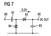
パワーハーベスタ43は、要求出力電圧を得るために必要に応じて、共振電圧トランス回路及びコッククロフトウォルトン電圧乗算器のいずれか又は両方を組み入れ得る。図7は、本発明のリモートコントロール装置におけるアップコンバータに適したパワーハーベスタ回路の実施形態について動作を説明する。入力信号60は、100pFキャパシタであり得るキャパシタ61においてRF周波数(例えば2.4GHz)で低インピーダンスを示すが、このキャパシタはDCブロックを提供する。電圧が高くなると、ダイオード62が導通し始め、電流を流し、別のキャパシタ63の高位プレートに電荷を供給する。電圧が低くなると、第1ダイオード62が逆バイアスとなり、他方のダイオード64が順バイアスになる。これにより第1キャパシタ61の充電が回復する。時間と共に結果としてDC出力65が生成される。
The
図8に代替形態が示されており、1/4波長線66を有する一対の整流器回路を使用する。線66の低位化を利用することにより、該線が共振してキャパシタ61へ現れる信号の振幅を増加させ、RF信号を整流してDC電圧を発生する前に、局部発振手段からの有効電圧を増加させるようにする。ダイオード64,62の寄生容量67,68に起因して、必要な線は実際には1/4波長以下である。当該整流器は2.44GHzにチューンされ、有効電圧は、新しい接地として効果的に機能する中間線の別のキャパシタ69を使用し、二つの出力65を加えて、同じ電流で2倍の電圧出力を得ることで、さらに増加する。
An alternative is shown in FIG. 8, which uses a pair of rectifier circuits having quarter wavelength lines 66. Utilizing the lowering of the
図9は、図1の実施形態で使用できるアップコンバータの代わりのタイプを示す。ミキサー23の代わりに、2ポートパラメトリックアンプが使用される。図9の例は、入力信号13を受信すると共に接地20されるシングルエンドの入力端21と、ダイポールアンテナ81,82へ接続される出力ポート34と、を有するパラメトリックアンプコア35を有する。通例では250MHz以下の入力信号13は、高Q副搬送波周波数入力インダクタ23を経て伝送され、シャント整合線対85を経た接地接続部33への「アースリターン」と並列のコモンモードのバラクタダイオード対83,84を駆動する。高インピーダンス(極小電流条件)電圧源が、例えば3Vのバイアス電圧22を、高Q副搬送波周波数入力整合チョーク86を経てバラクタダイオード対83,84(例えばBBY53−02V)へ提供し、正確な動作容量バイアスポイントを設定する。マイクロ波アンテナ81,82により受信された入射局部発振手段「ポンプ」信号7(例えば2.44GHzの周波数)は、適切な印刷マイクロ波直列整合線87,88及びシャント整合線85を経て伝送され、バラクタダイオード対83,84に差動駆動(中央接地33に対し)を提供する。この差動LO信号7がバラクタダイオード83,84においてコモンモード副搬送波周波数駆動信号13と混ざり、マイクロ波周波数下側波帯(LSB)及び上側波帯(USB)の結果を生成する。これら差動モードミキシング結果は、マイクロ波整合線87,88を通してマイクロ波アンテナ81,82へフィードバックされて転送され、トランシーバーのボアアレイへ戻される。
FIG. 9 shows an alternative type of upconverter that can be used in the embodiment of FIG. Instead of the
パラメトリックアンプ回路の二つのバラクタダイオード83,84は、「ポンプ」信号7を局部発振手段及び電力源として直接的に使用し、DC電源が不要である、アップコンバータ及びアンプとして働く。パラメトリックアンプは、代表的には、第1ポートがアップコンバート及び増幅対象の比較的低周波数の入力信号を受信し且つ第2ポートが比較的高周波数のポンプ信号を受信すると共に比較的高周波数のアップコンバート及び増幅ミキシング結果を出力する、2ポートデバイスである。
The two
例えば、パラメトリックアンプへのポンプ信号7は、リモートコントロール装置のDC電源を不要とするために、無線伝送から受信される。上及び下側波帯とポンプ信号7により占有される総帯域幅は、通例では、信号アンテナの効率的帯域幅内に収まるほどに小さい。したがって、2ポートパラメトリックアンプ回路は、第1ポート21がアップコンバート及び増幅対象の入力信号13を受信し、第2ポート34がポンプ信号7を受信し且つ上及び下側波帯周波数にアップコンバート及び増幅された入力信号8を出力するように、設けられる。
For example, the
ホスト送信器9からダイポールアンテナ81,82により受信された局部発振手段信号7は、通例+10dBmの電力レベルでマイクロ波ポート34に到達する。この「ポンプ」信号7は、印刷線整合87,88を経てバラクタダイオード対83,84へ伝送される。ダイポールアンテナ81,82からの平衡フィードの各半分にそれぞれ接続されたアノードをもつ、バラクタダイオード83,84の共通カソード形態により、LO(ポンプ)周波数でバラクタダイオードの逆位相刺激が生じる。副搬送波周波数入力インダクタ86を経た共通カソードノードの刺激は、入力周波数でバラクタダイオード83,84の同位相刺激を導く。二つのバラクタダイオードのそれぞれで結果的に発生されるLSB及びUSBは、したがって、逆位相である。入射LO信号7の大部分(反射部分)に伴うこれら所望の出力信号は、印刷線整合87,88を経てダイポールアンテナ81,82へ戻され、信号8がホスト9に受信されるべく放射される。
The local oscillation means
シングルエンド副搬送波周波数入力端21と直列の高Q副搬送周波数入力整合チョーク23は、副搬送波周波数でバラクタダイオード83,84の高容量リアクタンスと直列共振形である。副搬送波周波数フィード21に関するアースリターンは、マイクロ波ポートシャント線の中央接地33により提供される。マイクロ波ポートの中央接地シャントマイクロストリップ線は、バラクタダイオード83,84の高容量アドミッタンスの大部分とマイクロ波ポート周波数で共振する。そして直列線平衡対87,88は、バラクタダイオード83,84の容量リアクタンスの残りをチューンアウトし、インピーダンス伝送を完成してマイクロ波ダイポールアンテナ81,82の22Ω平衡負荷に整合する。
The high Q subcarrier frequency
この実施形態において、ダイオードは、副搬送波周波数フィードに対し並列に接続され、入力ポートに与えられる副搬送波周波数でバラクタダイオードの高インピーダンスを半分にする。ダイオードは、マイクロ波ポート34に対し直列に接続され、マイクロ波ポートに与えられる2.442GHzでバラクタダイオードの極低インピーダンスを倍増する。当該直列/並列形態は、シングルエンド駆動、平衡マイクロ波駆動、及び2ポート動作を自身に加える。パラメトリックアンプのシングルエンド駆動は、使用され得る副搬送波周波数に適切であり、副搬送波周波数入力チョーク86及びマイクロ波ポート電圧ノードのアース33を通した駆動手法によってもたらされる。平衡マイクロ波ポートは、ダイポールアンテナとの交信用に通例の2.5GHzで適切である。
In this embodiment, the diode is connected in parallel to the subcarrier frequency feed and halves the high impedance of the varactor diode at the subcarrier frequency applied to the input port. The diode is connected in series to the
上記マイクロ波ポートは、通例で2.5GHzのLO「ポンプ」フィードでも、2.5GHz±副搬送波周波数の出力周波数でも、十分に平衡動作する。副搬送波周波数は、例えば、キーボード、マウス、リモートコントロール、ゲームコントローラなどの装置次第で変更され得る。これは、マイクロ波ポート回路におけるいかなる低インピーダンス接地も不要とする。マイクロ波ポートの十分な平衡動作は、LO信号7を受信し且つLSB及びUSB信号8を再放射する平衡ダイポールアンテナ81,82との接続に完璧に適する。
The microwave port is well balanced, typically with a 2.5 GHz LO “pump” feed and with an output frequency of 2.5 GHz ± subcarrier frequency. The subcarrier frequency can be changed depending on devices such as a keyboard, a mouse, a remote control, and a game controller. This eliminates the need for any low impedance ground in the microwave port circuit. Fully balanced operation of the microwave port is perfectly suitable for connection with
パラメトリックアンプの実施形態に関するパワーハーベスティングは、上記ミキサーに関して述べたのと同様に機能する。DC電力は局部発振手段信号7から採取され、パラメトリックアンプ35のLNA32及びDCバイアス電圧22に必要な電力89を提供する。図10に示すように、電力分配器44を使用して、ポート34Bに受信される局部発振手段7を、マイクロ波ポート24用のポート34Aと整流器43用のポート34Cとに分配し、入射LO信号の一部を、局部発振手段電力を伝え且つアップコンバート後の側波帯を戻すマイクロ波周波数ポート34へつなぐと共に、電力分配器44からの信号の他の部分を、上述のようなパワーハーベスティング回路43へつなぐ。
Power harvesting for parametric amplifier embodiments functions in the same manner as described for the mixer above. The DC power is taken from the local oscillator means
アップコンバータ4へ入力される入力信号13は、ローノイズアンプ(LNA)32で増幅され、2ポートパラメトリックアンプ35の入力ポート21へ入力される。ホスト9のマイクロ波アンテナ3から放射された局部発振手段(LO)信号7は、パラメトリックアンプのマイクロ波周波数ポート34に接続されたマイクロ波アンテナ5に受信される。入力信号13及びLO信号7は、ホストアンテナ3の帯域幅内に留まる上及び下側波帯を生成し、該側波帯のいずれか又は両方がホスト9のレシーバーにより受信されるべく放射され、ホスト9が信号8を処理する。
The
一例において、リモートコントロール装置は、ワイヤレスコンピュータキーボード及びワイヤレスマウスの一つであり得る。本発明は、マイクロ波リンクを介したホストコンピュータとリモート付属品との間のワイヤレス通信をバッテリー不要で実施可能にする。ホストコンピュータは、リモートキーボード及びマウスとワイヤレス通信するが、そのキーボードやマウス内に追加の電源は不要である。低電力マイクロ波信号がホストコンピュータから送信されてリモートコントロール装置により受信され、そして、上述したミキサーやパラメトリックアンプの使用を経て局部電力を発生するために使用される。本発明によれば、バッテリーパックを不要とし、パワーハーベスティングアップコンバータ回路を集積回路で実現して極小スペースしかとらないようにし得るので、上記装置を現状よりも格段に小さく且つ軽くすることができる。使用時、バッテリー交換が不要になるので、実際にバッテリーを見つけて交換するフラストレーションを避けられるのはもちろん、より環境に優しい製品をもたらすことになる。リモート装置からは、同じ仕組みを使用して、情報を送信しホストへ戻すことが可能である(例えば、マウスクリックやキーボードストローク)。 In one example, the remote control device can be one of a wireless computer keyboard and a wireless mouse. The present invention enables wireless communication between a host computer and a remote accessory via a microwave link without the need for a battery. The host computer communicates wirelessly with the remote keyboard and mouse, but no additional power source is required in the keyboard or mouse. A low power microwave signal is transmitted from the host computer and received by the remote control device and is used to generate local power through the use of the mixer and parametric amplifier described above. According to the present invention, a battery pack is not required, and the power harvesting up-converter circuit can be realized by an integrated circuit so that only a very small space can be taken. Therefore, the apparatus can be much smaller and lighter than the present state. . When used, battery replacement is not necessary, so frustration to actually find and replace the battery can be avoided, as well as a more environmentally friendly product. From the remote device, it is possible to send information back to the host using the same mechanism (eg, mouse clicks and keyboard strokes).
他の実施形態として、上述の装置及び技術を使用したテレビ受像機用のワイヤレスリモートコントロールシステムがある。そのリモートコントロールは、TV、DVD、HiFiなどの消費者電子機器であるホストと、当該リモートコントロール内の追加電源を不要として、ワイヤレス通信することができる。チャンネル変更、音量、その他同様の情報が、リモートコントロールから送信されホストへ戻される。このような消費者電子機器との使用に関する他の応用例が、ホストとワイヤレス通信可能とされたワイヤレス電子ゲームコントローラユニットである。 Another embodiment is a wireless remote control system for a television receiver using the above-described devices and techniques. The remote control can perform wireless communication with a host which is a consumer electronic device such as a TV, a DVD, and a HiFi without using an additional power source in the remote control. Channel changes, volume, and other similar information is sent from the remote control and returned to the host. Another application for use with such consumer electronic devices is a wireless electronic game controller unit capable of wireless communication with a host.
Claims (11)
前記アンテナから入射するRF信号を分配する電力分配器と、
前記分配された入射RF信号から電力を発生するパワーハーベスタと、
前記分配された入射RF信号を受信するアップコンバータステージと、
を備え、
前記アップコンバータステージが、前記パワーハーベスタによる電力をバイアス電圧として利用する2ポートパラメトリックアンプを備え、
前記2ポートパラメトリックアンプの2ポートのうちの第1ポートが、アップコンバート対象のコントロール信号を受信し、
前記2ポートパラメトリックアンプの2ポートのうちの第2ポートが、前記分配された入射RF信号を受信し且つ該入射RF信号を局部発振手段として上及び下側波帯周波数にアップコンバートした前記コントロール信号を前記アンテナへ出力する、
ワイヤレスコントロール装置。 An antenna,
A power distributor for distributing an RF signal incident from the antenna;
A power harvester that generates power from the distributed incident RF signal;
An upconverter stage for receiving the distributed incident RF signal ;
With
The up-converter stage includes a two-port parametric amplifier that uses power from the power harvester as a bias voltage ;
The first port of the two ports of the two-port parametric amplifier receives a control signal to be up-converted,
The second port of the two ports of the two-port parametric amplifier receives the distributed incident RF signal and up-converts the incident RF signal to upper and lower sideband frequencies as local oscillation means. To the antenna ,
Wireless control device.
前記ローノイズアンプは、前記パワーハーベスタによる電力を利用する、
請求項1に記載のワイヤレスコントロール装置。 A low noise amplifier is provided in the first port of the two-port parametric amplifier ;
The low noise amplifier uses power from the power harvester.
The wireless control device according to claim 1.
前記バラクタダイオードは、前記第1ポートに対し並列に且つ前記第2ポートに対し直列に接続され、
前記第1ポートは、前記ローノイズアンプを介して前記コントロール信号を受信し、
前記第2ポートは、前記入射RF信号を受信し且つ前記アップコンバートしたコントロール信号を出力する、
請求項2に記載のワイヤレスコントロール装置。 The 2-port parametric amplifier includes a pair of varactor diodes connected between the first port and the second port;
The varactor diode is connected in parallel to the first port and in series to the second port;
The first port receives the control signal via the low noise amplifier,
The second port receives the incident RF signal and outputs the up-converted control signal.
The wireless control device according to claim 2.
前記アンテナから入射するRF信号を分配する電力分配器と、
前記分配された入射RF信号から電力を発生するパワーハーベスタと、
前記分配された入射RF信号を受信するアップコンバータステージと、
を備え、
前記アップコンバータステージが、ローノイズアンプ及び2ポートミキサーを備え、
前記2ポートミキサーの2ポートのうちの第1ポートが、アップコンバート対象のコントロール信号を受信し、
前記2ポートミキサーの2ポートのうちの第2ポートが、前記分配された入射RF信号を受信し且つ該入射RF信号を局部発振手段として上及び下側波帯周波数にアップコンバートした前記コントロール信号を前記アンテナへ出力し、
前記ローノイズアンプが、前記パワーハーベスタによる電力を利用する、
ワイヤレスコントロール装置。 An antenna,
A power distributor for distributing an RF signal incident from the antenna;
A power harvester that generates power from the distributed incident RF signal;
An upconverter stage for receiving the distributed incident RF signal;
With
The upconverter stage comprises a low noise amplifier and a two-port mixer;
The first port of the two ports of the two-port mixer receives a control signal of the upconversion-target,
The second port of the two ports of the two-port mixer receives the distributed incident RF signal and the control signal obtained by up-converting the incident RF signal to upper and lower sideband frequencies as local oscillation means. Output to the antenna ,
The low noise amplifier uses the power from the power harvester;
Wireless control device .
一方の前記出力が前記パワーハーベスタへ接続され且つ他方の前記出力が前記アップコンバータステージの前記第2ポートへ接続される、
請求項1〜6のいずれか1項に記載のワイヤレスコントロール装置。 The power distributor distributes the incident RF signal into two outputs;
One output is connected to the power harvester and the other output is connected to the second port of the upconverter stage;
The wireless control apparatus of any one of Claims 1-6 .
前記ホストは、前記RF信号を発生する信号発生器と、前記RF信号を送信するアンテナと、を備える、
ワイヤレスシステム。 A wireless control device according to any one of claims 1 to 10 and a host,
The host includes a signal generator that generates the RF signal, and an antenna that transmits the RF signal.
Wireless system.
Applications Claiming Priority (3)
| Application Number | Priority Date | Filing Date | Title |
|---|---|---|---|
| GB1006459.0 | 2010-04-19 | ||
| GB1006459.0A GB2479723B (en) | 2010-04-19 | 2010-04-19 | Wireless control device |
| PCT/GB2011/050712 WO2011131962A1 (en) | 2010-04-19 | 2011-04-11 | Wireless control device |
Publications (2)
| Publication Number | Publication Date |
|---|---|
| JP2013530574A JP2013530574A (en) | 2013-07-25 |
| JP5570653B2 true JP5570653B2 (en) | 2014-08-13 |
Family
ID=42245389
Family Applications (1)
| Application Number | Title | Priority Date | Filing Date |
|---|---|---|---|
| JP2013505538A Expired - Fee Related JP5570653B2 (en) | 2010-04-19 | 2011-04-11 | Wireless control device |
Country Status (9)
| Country | Link |
|---|---|
| US (1) | US20130127605A1 (en) |
| EP (1) | EP2561620B1 (en) |
| JP (1) | JP5570653B2 (en) |
| CN (1) | CN102859566B (en) |
| BR (1) | BR112012026476A2 (en) |
| CA (1) | CA2796654A1 (en) |
| GB (1) | GB2479723B (en) |
| RU (1) | RU2523949C2 (en) |
| WO (1) | WO2011131962A1 (en) |
Families Citing this family (13)
| Publication number | Priority date | Publication date | Assignee | Title |
|---|---|---|---|---|
| DE102012210784B4 (en) * | 2012-06-25 | 2015-11-05 | Fraunhofer-Gesellschaft zur Förderung der angewandten Forschung e.V. | Transponder for home automation systems |
| GB2517907B (en) | 2013-08-09 | 2018-04-11 | Drayson Tech Europe Ltd | RF Energy Harvester |
| DE102014105911A1 (en) * | 2014-04-28 | 2015-10-29 | Phoenix Contact Gmbh & Co. Kg | Parameterizable power supply unit |
| DE102014217911A1 (en) * | 2014-09-08 | 2016-03-10 | Siemens Aktiengesellschaft | Arrangement and method for galvanically separated energy transmission |
| US10146317B2 (en) * | 2014-12-12 | 2018-12-04 | Ford Global Technologies, Llc | Vehicle accessory operation based on motion tracking |
| CN105162335A (en) * | 2015-05-25 | 2015-12-16 | 华南理工大学 | High-efficiency rectifier circuit covering wide input power range |
| WO2017172899A1 (en) | 2016-03-29 | 2017-10-05 | University Of Washington | Two-port mixers and systems, receivers, and methods using same |
| CN108736945A (en) * | 2017-04-20 | 2018-11-02 | 广东顺德中山大学卡内基梅隆大学国际联合研究院 | Single antenna passive data emission system and its implementation based on timeslice poll |
| GB2573502A (en) * | 2018-03-29 | 2019-11-13 | Drayson Tech Europe Ltd | Method and apparatus |
| GB2579588B (en) * | 2018-12-04 | 2020-12-23 | Drayson Tech Europe Ltd | Power electronics for use in smart cards and other applications |
| US11424772B2 (en) | 2018-12-06 | 2022-08-23 | Berex, Inc. | Receiver architectures with parametric circuits |
| US11861445B2 (en) | 2020-03-11 | 2024-01-02 | Sato Holdings Kabushiki Kaisha | Electromagnetic coupler arrangement |
| JP2022070600A (en) * | 2020-10-27 | 2022-05-13 | キヤノン株式会社 | Wireless power transmission system, control method for wireless power transmission system, and program |
Family Cites Families (28)
| Publication number | Priority date | Publication date | Assignee | Title |
|---|---|---|---|---|
| NL6700436A (en) * | 1966-01-28 | 1967-07-31 | ||
| US3591848A (en) * | 1968-07-25 | 1971-07-06 | Gen Electric | Parametric amplifier employing self-biased nonlinear diodes |
| US5247305A (en) * | 1990-10-10 | 1993-09-21 | Nippondenso Co., Ltd. | Responder in movable-object identification system |
| US5365230A (en) | 1993-03-15 | 1994-11-15 | Cordata, Inc. | Inductively coupled keyboard |
| US5363071A (en) * | 1993-05-04 | 1994-11-08 | Motorola, Inc. | Apparatus and method for varying the coupling of a radio frequency signal |
| US6138050A (en) | 1997-09-17 | 2000-10-24 | Logitech, Inc. | Antenna system and apparatus for radio-frequency wireless keyboard |
| GB9808762D0 (en) * | 1998-04-25 | 1998-06-24 | Marconi Gec Ltd | Modulated reflector circuit |
| DE19823049C2 (en) * | 1998-05-22 | 2000-09-21 | Ericsson Telefon Ab L M | Power amplifier output circuit for suppressing harmonics for a mobile radio unit with double band operation and method for operating the same |
| GB2344021B (en) * | 1998-11-18 | 2003-06-18 | Roke Manor Research | Improvements in or relating to tagging systems |
| AU4137200A (en) * | 1999-05-03 | 2000-11-17 | Trolley Scan (Pty) Limited | Energy transfer in an electronic identification system |
| US6950634B2 (en) * | 2002-05-23 | 2005-09-27 | Freescale Semiconductor, Inc. | Transceiver circuit arrangement and method |
| US7697946B2 (en) * | 2002-06-04 | 2010-04-13 | Forster Ian J | Reflective communication using radio-frequency devices |
| GB0217932D0 (en) * | 2002-08-02 | 2002-09-11 | Koninkl Philips Electronics Nv | High frequency module |
| US7508898B2 (en) * | 2004-02-10 | 2009-03-24 | Bitwave Semiconductor, Inc. | Programmable radio transceiver |
| JP2006142856A (en) * | 2004-11-16 | 2006-06-08 | Alps Electric Co Ltd | Tire information detection device |
| DE102005022551B4 (en) * | 2005-05-17 | 2010-02-11 | Siemens Ag | A method of performing a magnetic resonance examination, a magnetic resonance apparatus and an array for receiving magnetic resonance signals |
| ZA200710464B (en) | 2005-06-08 | 2009-07-29 | Powercast Corp | Powering devices using RF energy harvesting |
| WO2007073099A1 (en) * | 2005-12-22 | 2007-06-28 | Lg Innotek Co., Ltd | Rfid system |
| CN101030757A (en) * | 2006-03-01 | 2007-09-05 | 西门子公司 | Mixing circuit for balanced mixer with varactor |
| US7952467B2 (en) * | 2006-09-29 | 2011-05-31 | Sony Corporation | System and method for informing user how to use universal remote control |
| WO2008068078A1 (en) * | 2006-12-07 | 2008-06-12 | International Business Machines Corporation | Remote controller having an rfid tag |
| US20080143192A1 (en) * | 2006-12-14 | 2008-06-19 | Sample Alanson P | Dynamic radio frequency power harvesting |
| JP4823943B2 (en) * | 2007-03-06 | 2011-11-24 | 均 北吉 | Wireless tag, wireless tag reader, pulse encoding key detection circuit, and wireless tag system using them |
| JP2008228136A (en) * | 2007-03-15 | 2008-09-25 | Sony Corp | Data transmission apparatus |
| JP5155642B2 (en) * | 2007-11-28 | 2013-03-06 | ルネサスエレクトロニクス株式会社 | ID tag |
| JP2010050942A (en) * | 2008-08-25 | 2010-03-04 | Shojiro Terajima | Remote controller and manipulator |
| GB0820692D0 (en) * | 2008-11-12 | 2008-12-17 | Siemens Ag | Amplifier |
| US8159396B2 (en) * | 2009-10-30 | 2012-04-17 | General Electric Company | Wireless proximity probe and method of operating same |
-
2010
- 2010-04-19 GB GB1006459.0A patent/GB2479723B/en not_active Expired - Fee Related
-
2011
- 2011-04-11 US US13/642,173 patent/US20130127605A1/en not_active Abandoned
- 2011-04-11 BR BR112012026476A patent/BR112012026476A2/en not_active IP Right Cessation
- 2011-04-11 JP JP2013505538A patent/JP5570653B2/en not_active Expired - Fee Related
- 2011-04-11 CN CN201180019929.3A patent/CN102859566B/en not_active Expired - Fee Related
- 2011-04-11 RU RU2012148813/08A patent/RU2523949C2/en not_active IP Right Cessation
- 2011-04-11 CA CA2796654A patent/CA2796654A1/en not_active Abandoned
- 2011-04-11 EP EP11718475.4A patent/EP2561620B1/en not_active Not-in-force
- 2011-04-11 WO PCT/GB2011/050712 patent/WO2011131962A1/en active Application Filing
Also Published As
| Publication number | Publication date |
|---|---|
| WO2011131962A1 (en) | 2011-10-27 |
| EP2561620B1 (en) | 2014-12-17 |
| RU2012148813A (en) | 2014-05-27 |
| BR112012026476A2 (en) | 2016-08-16 |
| CA2796654A1 (en) | 2011-10-27 |
| CN102859566B (en) | 2014-10-15 |
| GB2479723A (en) | 2011-10-26 |
| CN102859566A (en) | 2013-01-02 |
| RU2523949C2 (en) | 2014-07-27 |
| GB201006459D0 (en) | 2010-06-02 |
| GB2479723B (en) | 2013-01-23 |
| EP2561620A1 (en) | 2013-02-27 |
| US20130127605A1 (en) | 2013-05-23 |
| JP2013530574A (en) | 2013-07-25 |
Similar Documents
| Publication | Publication Date | Title |
|---|---|---|
| JP5570653B2 (en) | Wireless control device | |
| US9837857B2 (en) | Rectenna | |
| US20190296586A1 (en) | Portable Pad for Wireless Charging | |
| US9305192B2 (en) | Tuneable NFC-enabled device | |
| TWI375353B (en) | Multiple frequency antenna array for use with an rf transmitter or transceiver | |
| US20110062788A1 (en) | Wirless power supply device | |
| CN104659927A (en) | Wireless charging receiving device and wireless charging system using the same | |
| US8654012B2 (en) | Tag antenna using microstrip line, method of manufacturing the same and radio frequency identification tag | |
| US8421460B2 (en) | Upconverter | |
| CN101978608A (en) | Apparatus comprising a broadcast receiver circuit and provided with an antenna | |
| KR101837121B1 (en) | Dual band Wireless Power Receiving Unit | |
| US9698871B2 (en) | Near field communications apparatus | |
| JP2010530098A (en) | Tag device, reader device, RFID system | |
| CN108737999A (en) | Near field communication means | |
| Lu et al. | Optimal power splitting of wireless information and power transmission using a novel dual-channel rectenna | |
| TW201042871A (en) | Wireless power-supply devices | |
| KR100952978B1 (en) | Radio frequency identification tag antenna for attaching to metal | |
| US6346912B1 (en) | Radio frequency beacon | |
| CN1989699A (en) | Mobile telephone device | |
| JP2003323595A (en) | Contactless ic card reader-writer device | |
| US11481595B2 (en) | Dual system RFID tag | |
| Cansiz | Measurement and analysis of significant effects on charging times of radio frequency energy harvesting systems | |
| CN113794451A (en) | Low-power consumption single-ended reflection amplifier circuit based on oscillation negative resistance characteristic | |
| WO2004001939A1 (en) | A rectifier | |
| JP2011239340A (en) | Radio communication device and radio communication system |
Legal Events
| Date | Code | Title | Description |
|---|---|---|---|
| A977 | Report on retrieval |
Free format text: JAPANESE INTERMEDIATE CODE: A971007 Effective date: 20140128 |
|
| A131 | Notification of reasons for refusal |
Free format text: JAPANESE INTERMEDIATE CODE: A131 Effective date: 20140204 |
|
| A521 | Written amendment |
Free format text: JAPANESE INTERMEDIATE CODE: A523 Effective date: 20140501 |
|
| TRDD | Decision of grant or rejection written | ||
| A01 | Written decision to grant a patent or to grant a registration (utility model) |
Free format text: JAPANESE INTERMEDIATE CODE: A01 Effective date: 20140527 |
|
| A61 | First payment of annual fees (during grant procedure) |
Free format text: JAPANESE INTERMEDIATE CODE: A61 Effective date: 20140624 |
|
| R150 | Certificate of patent or registration of utility model |
Ref document number: 5570653 Country of ref document: JP Free format text: JAPANESE INTERMEDIATE CODE: R150 |
|
| LAPS | Cancellation because of no payment of annual fees |