JP5568271B2 - Heat recovery equipment - Google Patents
Heat recovery equipment Download PDFInfo
- Publication number
- JP5568271B2 JP5568271B2 JP2009215735A JP2009215735A JP5568271B2 JP 5568271 B2 JP5568271 B2 JP 5568271B2 JP 2009215735 A JP2009215735 A JP 2009215735A JP 2009215735 A JP2009215735 A JP 2009215735A JP 5568271 B2 JP5568271 B2 JP 5568271B2
- Authority
- JP
- Japan
- Prior art keywords
- heat
- power
- heat recovery
- metal material
- rolling line
- Prior art date
- Legal status (The legal status is an assumption and is not a legal conclusion. Google has not performed a legal analysis and makes no representation as to the accuracy of the status listed.)
- Active
Links
Images


Classifications
-
- H—ELECTRICITY
- H10—SEMICONDUCTOR DEVICES; ELECTRIC SOLID-STATE DEVICES NOT OTHERWISE PROVIDED FOR
- H10N—ELECTRIC SOLID-STATE DEVICES NOT OTHERWISE PROVIDED FOR
- H10N10/00—Thermoelectric devices comprising a junction of dissimilar materials, i.e. devices exhibiting Seebeck or Peltier effects
- H10N10/10—Thermoelectric devices comprising a junction of dissimilar materials, i.e. devices exhibiting Seebeck or Peltier effects operating with only the Peltier or Seebeck effects
- H10N10/13—Thermoelectric devices comprising a junction of dissimilar materials, i.e. devices exhibiting Seebeck or Peltier effects operating with only the Peltier or Seebeck effects characterised by the heat-exchanging means at the junction
Landscapes
- Metal Rolling (AREA)
- Charge And Discharge Circuits For Batteries Or The Like (AREA)
Description
本発明は、金属材料を加工する熱間圧延ラインの熱回収装置に関する。 The present invention relates to a heat recovery apparatus for a hot rolling line that processes a metal material.
金属材料を圧延する圧延ラインとして、鉄鋼の板を製造する熱間薄板圧延、厚板圧延、冷間圧延のライン、鉄鋼の形鋼圧延、棒鋼、線材の圧延ライン、及びアルミニウムや銅の圧延ライン等がある。これらのうち、エネルギーを大量に消費する圧延ラインは、熱間圧延ラインである。熱間圧延ラインでは、処理対象の金属材料を高温に熱して柔らかくした後に、大きな変形を加えるためである。特に、熱間薄板圧延ラインや熱間厚板圧延ラインは、工場自体が大きく、消費エネルギーが大きい。 As a rolling line for rolling metal materials, hot thin plate rolling, steel plate rolling, cold rolling line, steel shape rolling, steel bar rolling, wire rod rolling line, and aluminum and copper rolling line producing steel plate Etc. Among these, the rolling line that consumes a large amount of energy is a hot rolling line. This is because in the hot rolling line, the metal material to be treated is heated to a high temperature and softened, and then a large deformation is applied. In particular, the hot sheet rolling line and the hot plate rolling line are large in the factory itself and consume large energy.
熱間圧延ラインにおいて高温になる金属材料から放出される熱エネルギーの回収や再利用は、今のところ十分できていない。各圧延工程において、金属材料からの放射や対流による熱エネルギーは周囲の大気を暖めるだけである。また、冷却に使用された水に含まれる熱も、回収された水が工場の外部で冷却されるだけのことが多く、回収して再利用されることは少ない。 At present, recovery and reuse of thermal energy released from a metal material that becomes high temperature in a hot rolling line has not been sufficiently achieved. In each rolling process, heat energy from radiation and convection from the metal material only warms the surrounding atmosphere. In addition, the heat contained in the water used for cooling is often just the recovered water being cooled outside the factory, and is rarely recovered and reused.
近年、冷却水に含まれる熱を回収するために、圧延機の冷却装置及び熱回収装置が提案されている(例えば、特許文献1参照)。例えば自治体が運用しているごみ焼却工場において、ごみを焼却した熱で水を加熱して十分に高温の水等が得られる場合には、蒸気化してタービンを回して発電に利用できる場合がある。また100℃以下の低温の水は、ごみ焼却工場に隣接した温泉施設等に提供されることがある。 In recent years, in order to recover the heat contained in the cooling water, a cooling device and a heat recovery device of a rolling mill have been proposed (for example, see Patent Document 1). For example, in a waste incineration plant operated by the local government, if water is heated with the heat generated by incineration of the waste water and sufficiently high temperature water is obtained, it may be vaporized and used for power generation by turning the turbine. . In addition, low temperature water of 100 ° C. or lower may be provided to a hot spring facility or the like adjacent to a waste incineration plant.
しかしながら、熱間圧延ラインにおいて熱を回収したとしても、そのまま再利用することは一般には難しい。十分に高温の水等が得られる場合には、高温蒸気を作って発電に利用できる場合があるが、十分高温の水や媒体が得られない場合の熱の再利用は特に難しい。一般には、温泉施設で再利用する等の特殊な場合を除いて、熱を電力に変換した方がエネルギー形態として利用の自由度が高い。電力も貯蔵するには難があるエネルギー形態であるが、最近は高性能な2次電池等の電力貯蔵装置も開発されている。 However, even if heat is recovered in the hot rolling line, it is generally difficult to reuse it as it is. When sufficiently hot water or the like can be obtained, high-temperature steam may be produced and used for power generation, but heat reuse is particularly difficult when sufficiently hot water or medium cannot be obtained. In general, except for special cases such as reuse in hot spring facilities, converting heat into electric power has a higher degree of freedom in use as an energy form. Although it is a form of energy that is difficult to store electric power, recently, a power storage device such as a high-performance secondary battery has been developed.
上記問題点に鑑み、本発明は、熱間圧延ラインにおける金属材料の処理により発生する熱を回収して、電力として貯蔵する熱回収装置を提供することを目的とする。 In view of the above problems, an object of the present invention is to provide a heat recovery apparatus that recovers heat generated by processing a metal material in a hot rolling line and stores it as electric power.
本発明の一態様によれば、金属材料を加熱して圧延する熱間圧延ラインの熱回収装置であって、金属材料で発生する熱を収集する集熱手段、集熱手段によって集められた熱の凝集化を行う熱凝集化手段、及び熱凝集化手段により凝集化された熱を電力に変換する変換手段を有し、熱間圧延ラインにおける金属材料の処理によって発生して金属材料から大気中に放出された熱を、処理による金属材料の加熱及び変形加工と並行して大気中で収集し、収集された熱を電力に変換する、金属材料と大気を介して対向して配置された熱電変換手段と、熱電変換手段により変換された電力を蓄える電力貯蔵手段と、熱電変換手段により生成される生成電力、及び熱凝集化手段により消費される消費電力をそれぞれ予測する電力予測手段と、生成電力と消費電力に基づき、熱回収を行うか否かを判断する判断手段とを備える熱回収装置が提供される。 According to one aspect of the present invention, there is provided a heat recovery apparatus for a hot rolling line that heats and rolls a metal material, the heat collecting means for collecting heat generated in the metal material, and the heat collected by the heat collecting means. A heat aggregating means for agglomerating the heat and a converting means for converting the heat agglomerated by the heat aggregating means into electric power, which is generated by the processing of the metal material in the hot rolling line and is converted into the atmosphere The heat released to the metal material is collected in the atmosphere in parallel with the heating and deformation processing of the metal material by the treatment, and the collected heat is converted into electric power. A conversion means, a power storage means for storing the power converted by the thermoelectric conversion means, a power prediction means for predicting the generated power generated by the thermoelectric conversion means, and the power consumption consumed by the thermal aggregating means, and generation Power and power off Based on the power, a heat recovery device and a determination unit for determining whether to perform the heat recovery is provided.
本発明によれば、熱間圧延ラインにおける金属材料の処理により発生する熱を回収して、電力として貯蔵する熱回収装置を提供できる。 ADVANTAGE OF THE INVENTION According to this invention, the heat recovery apparatus which collect | recovers the heat which generate | occur | produces by the process of the metal material in a hot rolling line, and stores it as electric power can be provided.
次に、図面を参照して、本発明の第1乃至第4の実施形態を説明する。以下の図面の記載において、同一又は類似の部分には同一又は類似の符号を付している。ただし、図面は模式的なものである。又、以下に示す第1乃至第4の実施形態は、この発明の技術的思想を具体化するための装置や方法を例示するものであって、この発明の実施形態は、構成部品の構造、配置等を下記のものに特定するものでない。この発明の実施形態は、特許請求の範囲において、種々の変更を加えることができる。 Next, first to fourth embodiments of the present invention will be described with reference to the drawings. In the following description of the drawings, the same or similar parts are denoted by the same or similar reference numerals. However, the drawings are schematic. Further, the following first to fourth embodiments exemplify apparatuses and methods for embodying the technical idea of the present invention, and the embodiments of the present invention include the structure of component parts, The layout is not specified as follows. The embodiment of the present invention can be variously modified within the scope of the claims.
(第1の実施形態)
本発明の第1の実施形態に係る熱回収装置10は、金属材料100を加熱して圧延する熱間圧延ライン20で発生する熱を回収する熱回収装置であって、図1に示すように、熱間圧延ライン20における金属材料100の処理によって発生する熱を電力に変換する熱電変換手段11と、熱電変換手段11により変換された電力を蓄える電力貯蔵手段12とを備える。熱電変換手段11は、金属材料100で発生する熱を収集する集熱手段111と、集熱手段111により集められた熱を電力に変換する変換手段112とを備える。更に、熱回収装置10は、電力貯蔵手段12に貯蔵された電力量を表示する表示手段13を備える。
(First embodiment)
The
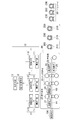
図1は、熱間圧延ライン20が熱間薄板圧延ラインである場合の構成例を示している。熱間薄板圧延ラインでは、「スラブ」と呼ばれる直方体状の金属材料100を加熱炉21で熱し、粗圧延機22で数パスの圧延を施して、厚み30mm〜40mm程度のバーを生成する。金属材料100は、熱間圧延ライン20で行われる圧延の各処理工程を経る度に、バー、ストリップ、板等と呼び方が変わるが、以下では「金属材料」という呼称で統一する。
FIG. 1 shows a configuration example when the hot
粗圧延機22で圧延された金属材料100は、仕上圧延機24に搬送される。粗圧延機22から仕上圧延機24に金属材料100を搬送する間、金属材料100の温度低下を防ぐために保熱カバー23で搬送路を覆ってもよい。保熱カバー23が開閉できるようにして、保熱する場合には搬送路を覆うために閉じ、使用しない場合には搬送路を開放するようにしてもよい。仕上圧延機24では、金属材料100を製品厚み1.2mm〜12mm程度に圧延する。
The
その後、水冷装置25によって金属材料100に注水することで、巻取機26前で金属材料100は冷却される。金属材料100は、最終的に巻取機26で巻き取られ、製品コイル200が製造される。製品コイル200は、巻取機26から抜き取られた後、コイルカー210に搭載されて製品コイル200の貯蔵場所であるコイルヤード30に搬送される。製品コイル200は、コイルヤード30の所定の場所で、出荷まで保管される。製品コイル200は、更に冷間圧延工程を経ることもあるが、建材等の用途によってはそのまま使用されることがある。
Thereafter, the
熱間薄板圧延ラインにおける代表的な金属材料100の温度は,加熱炉21出側で1200℃〜1250℃、粗圧延機22出側で1100℃〜1150℃、仕上圧延機24入側で1050℃〜1100℃、仕上圧延機24出側で850℃〜900℃、巻き取り温度は500℃〜700℃である。高品質の材質造り込みのために、巻き取り温度を300℃前後まで下げることもある。
The temperature of the
上記のように熱間圧延ライン20内で高温になる金属材料100で発生する熱を効率的に集熱するために、本発明の実施形態に係る熱回収装置10の熱電変換手段11は、熱間圧延ライン20中を運搬される金属材料100の至近距離に配置されることが好ましい。
As described above, in order to efficiently collect the heat generated in the
熱回収装置10は、1つ又は複数の熱電変換手段11を有し、高効率を維持するために集熱手段111の直近に変換手段112が取り付けられる。集熱手段111を配置するのに好適な場所は、デスケーラ等の水が飛散してこない場所、金属材料100の上反りが小さい場所、金属材料100が比較的滞留する場所、金属材料100が高温である場所等である。例えば、加熱炉21を出た金属材料100が粗圧延機22の入側に到達する前の搬送路上(図1中、「R1」で示す。)、粗圧延機22と仕上圧延機24の間に配置される搬送テーブル(図1中、「R2」で示す。)等に集熱手段111を配置する。その他の位置の搬送テーブルでも上記条件を満たせば、短い搬送テーブルであっても熱間圧延ライン20内の任意の場所に集熱手段111を設置できる。
The
したがって、熱電変換手段11を配置する場所は、図1の場所R1、R2のいずれかに限られることはなく、場所R1、R2の両方に配置してもよい。更に、場所R1、R2以外の任意の場所に複数の熱電変換手段11を配置できる。 Therefore, the place where the thermoelectric conversion means 11 is arranged is not limited to any one of the places R1 and R2 in FIG. 1 and may be arranged in both the places R1 and R2. Furthermore, the several thermoelectric conversion means 11 can be arrange | positioned in arbitrary places other than the places R1 and R2.
図2に、集熱手段111と変換手段112の配置例を示す。テーブルロール27によって熱間圧延ライン20内を金属材料100が搬送される。保熱カバー23は、搬送テーブルの上の金属材料100を搬送テーブルとともに覆うように、開閉できる機構を備えている。図2は、保熱カバー23を開いた状態を示す。保熱カバー23を閉じたときに、上反りした金属材料100が保熱カバー23に衝突しないように、上反り矯正装置28が保熱カバー23の入り側に設置される。
FIG. 2 shows an arrangement example of the heat collecting means 111 and the converting
図2に示した例では、保熱カバー23の内部に変換手段112の一部である熱電素子110を多数取り付ける。このため、保熱カバー23を閉じたときに、金属材料100と熱電素子110とが対向する。このとき、金属材料100と金属材料100に対向する保熱カバー23の内面との間隔は、例えば300mm〜500mm程度である。
In the example shown in FIG. 2, a large number of
ただし、粗圧延機22で圧延された金属材料100の温度は1100℃前後であるため、熱電素子110が破壊される場合もありえる。また、熱電素子110を隙間なく配置することがコスト的に難しい場合もある。このため、熱電素子110の保護及び熱の偏在を少なくし熱分布の均一化のために、図3に示すように、例えば集熱板を集熱手段111として熱電素子110を覆うように設置する。図3は、金属材料100の搬送方向と垂直な方向に沿った断面図である。
However, since the temperature of the
保熱カバー23の金属材料100に対向する内面には、例えば石綿やガラス繊維等の断熱材が使用される。これは、金属材料100からの熱を保熱カバー23の外部に伝えないようにするためである。集熱板には、(1)保熱カバー23の配置された位置で表面温度が1000℃〜1100℃くらいである金属材料100からの熱に耐えられること、(2)熱伝導率が小さくないこと、(3)熱を吸収しやすく、熱を熱電素子110に伝えやすいこと、等の条件を満たす材料を採用可能である。(3)の条件を満たすために、集熱板は比熱が小さい材料であることが好ましい。
A heat insulating material such as asbestos or glass fiber is used on the inner surface of the
例えば、平均的に(1)〜(3)の条件を満たしている一般の鉄鋼材料が、集熱板に使用できる。一方、銅は熱伝導率が大きいが、融点が1100℃以下なので、(1)の条件を満たさない。(2)、(3)の条件から、セラミック材は集熱板に不向きである。 For example, a general steel material that satisfies the conditions (1) to (3) on average can be used for the heat collecting plate. On the other hand, copper has a large thermal conductivity, but since the melting point is 1100 ° C. or lower, the condition (1) is not satisfied. From the conditions (2) and (3), the ceramic material is unsuitable for the heat collecting plate.
保熱カバー23が配置されていない場所においても、上記と同様の構成により、搬送テーブルの上部を覆うように熱電素子110と集熱板を設置することにより、金属材料100の温度に近い高温の熱を熱電素子110で捉えることができる。その結果、効率良く熱を電力に変換できる。熱を電力に変える熱電素子110には、例えば、熱を与えると電圧が発生するゼーベック効果を利用した素子を採用可能である。ゼーベック素子の現状の熱電変換効率は7〜8%程度であり、一般に、2次曲線のように周囲温度が高温であるほど熱電変換効率が高くなる特徴を持つ。
Even in a place where the
上記のように熱電変換手段11により熱から変換された電力は、電力貯蔵手段12に貯蔵される。金属材料100の熱電変換手段11近傍の通過は間歇的であり、常に熱から電力へ変換できるわけではないので、図1に示した熱回収装置10を直接電力系統に接続することが困難なためである。電力貯蔵手段12には、例えば2次電池等が採用可能である。電力貯蔵手段12に蓄えられた電力量は、表示手段13によって表示される。このため、電力貯蔵手段12を電力系統に接続したり、工場内の電力源として使用する可動化の判断が容易である。表示手段13は、例えば電力量を数値やグラフで表示するディスプレイ等である。
The electric power converted from heat by the thermoelectric conversion means 11 as described above is stored in the electric power storage means 12. Since the passage of the
以上に説明したように、図1に示した熱回収装置10によれば、熱間圧延ライン20の近傍に1つ又は複数の熱電変換手段11を配置することにより、熱間圧延ライン20で実行される複数の処理工程のうちの少なくとも1の処理工程に起因して金属材料100で発生する熱を、電力に変換できる。つまり、熱間圧延ライン20の加熱炉21から巻取機26までに搬送や圧延を繰り返す過程で、高温の金属材料100から効率よく熱を回収できる。
As described above, according to the
例えば、加熱炉21から取り出された金属材料100の温度が1200℃であり、金属材料100の重量が20トン、比熱が0.15×4.19(kJ/kg/℃)である場合に、金属材料100が最終的に600℃まで冷却されると、7,542,000kJの熱エネルギーが周囲の空気と冷却水に奪われることになる。空冷は考慮せずに、20℃の冷却水だけで金属材料100を冷却し、冷却水全てを100℃まで熱すると、22,500kg(=7,542,000/4.19/(100−20))の冷却水が必要となる。つまり、22.5トンの沸騰水を作ることになる。また、7,542,000kJのエネルギーのうち、空冷や放射により奪われる熱が30%であると仮定し、そのうちの5%を回収できるとすれば、113,130kJ(=キロワット秒)の熱エネルギーを31キロワット時の電気エネルギーに変換できる。31キロワット時の電力量は,定格10kWの小型電動機を、定格状態で約3時間駆動できる電力に相当する。ここで回収効率を5%と仮定したのは、熱電素子110の熱電変換効率が7〜8%程度であっても、周辺機器の効率等を考慮すると、熱電変換効率が7〜8%より低下することが確実だからである。
For example, when the temperature of the
上記の数値例は金属材料100が1本だけの試算であり、金属材料100が数十、数百本単位になると非常に多くの電力を作り出すことができる。また上記例では5%と仮定した熱電素子110の熱電変換効率を改善することにより、更に多くの熱から電力への変換が期待できる。
The above numerical example is a trial calculation with only one
熱間圧延ラインは多くの熱が発生するプラントであるものの、一般には低温でしか回収できない、いわゆる低品質エネルギーが主なものである。例えば、金属材料を冷却した後の水は数十℃までは上昇するが、数十℃の水からエネルギーを回収することは非常に難しい。そのため、これらのエネルギーは大気中に放出されるだけであるのが、従来は一般的であった。 Although the hot rolling line is a plant that generates a lot of heat, generally, so-called low-quality energy that can be recovered only at a low temperature is the main one. For example, the water after cooling the metal material rises to several tens of degrees Celsius, but it is very difficult to recover energy from the water of several tens of degrees Celsius. Therefore, it has been common in the past that these energies are only released into the atmosphere.
本発明の第1の実施形態に係る熱回収装置10では、熱間圧延ライン20を伝搬する金属材料100の直近に熱を電力に変換する熱電変換手段11を配置し、金属材料100から発せられる熱を電力に変換する。その結果、大気中に逃されていただけのエネルギーを効率よく回収することができる。つまり、図1に示した熱回収装置10によれば、熱間圧延ライン20で金属材料100が生する熱を効率的に回収して、電力として貯蔵する熱回収装置を提供できる。
In the
(第2の実施形態)
本発明の第2の実施形態に係る熱回収装置10は、図4に示すように、熱間圧延ライン20により製造された製品コイル200を熱回収の対象としていることが、図1の熱回収装置10と異なる。その他の構成については、図1に示す第1の実施形態と同様である。
(Second Embodiment)
As shown in FIG. 4, the
巻取機26から抜き出され、コイルカー210に搭載された製品コイル200がコイルヤード30に搬送される搬送路に、図1において説明した熱間圧延ライン20内の搬送路と同様に、集熱手段111と変換手段112を設置する。ただし、熱間圧延ライン20内に集熱手段111と変換手段112を設置する場合と異なり、製品コイル200が搬送される搬送路に集熱手段111と変換手段112を設置する場合は、水の飛散や金属材料100の上反りといった問題がなく、また温度も比較的低温である。このため、集熱手段111の配置について特殊な考慮をする必要がほとんどない。むしろ集熱手段111が不要な場合がある。
As with the conveyance path in the
コイルヤード30に熱電変換手段11を設置する場合には、製造直後のまだ熱い製品コイル200に対して集熱手段111と変換手段112を設置しなければならない。そのため、熱い製品コイル200の置き場所を決めて、その場所に集熱手段111と変換手段112を設置する。或いは、集熱手段111と変換手段112、及び電力貯蔵手段12を一体化して移動可能とし、熱い製品コイル200の近くで使用してもよい。
When the thermoelectric conversion means 11 is installed in the coil yard 30, the heat collection means 111 and the conversion means 112 must be installed for the still
巻取機26から抜き出した直後の製品コイル200は400℃〜600℃という高温の状態であり、かつ、容易に製品コイル200の搬送路の至近距離に熱電変換手段11を配置することができる。このため、第2の実施形態に係る熱回収装置10においても、効率のよい熱電変換が可能である。なお、熱間圧延ライン20からコイルヤード30に製品コイル200が搬送されるまでの搬送路、及びコイルヤード30に熱電変換手段11を設置し、かつ、熱間圧延ライン20に熱電変換手段11を設置してもよいことはもちろんである。他は、第1の実施形態と実質的に同様であり、重複した記載を省略する。
The
(第3の実施形態)
本発明の第3の実施形態に係る熱回収装置10は、図5に示すように、熱電変換手段11が、集熱手段111によって集められた熱の凝集化を行う熱凝集化手段113を更に備えることが、図1の熱回収装置10と異なる。変換手段112は、熱凝集化手段113によって凝集化された熱を電力に変換する。その他の構成については、図1に示した第1の実施形態と同様である。
(Third embodiment)
As shown in FIG. 5, the
図1及び図4に示した熱回収装置10では、集熱手段111が金属材料100又は製品コイル200の直近に設置される。これにより、主に金属材料100や製品コイル200からの放射熱を効率的に取り込む。
In the
これに対し、図5に示した熱回収装置10では、金属材料100や製品コイル200からの放射熱ではなく、主に対流による熱の回収を行う。このため、熱間圧延ライン20或いは金属材料100の上方に集熱手段111が設置される。例えば、加熱炉21の扉を開けたときに加熱炉21内の熱が出てくるので、加熱炉21の扉の上方はかなり高温になる。このため、加熱炉21の扉の上方や、粗圧延機22の上方等の、金属材料100の温度が高い熱間圧延ライン20の上流側で、特に効果的に集熱できる。
On the other hand, the
集熱手段111は、上記の目的から、対流による熱を効果的に集める形態とすることが好ましい。例えば、傘を広げたような上部ほど狭くなる形状を持つ集熱手段111を採用可能である。この狭い上部に変換手段112を取り付ける。 The heat collecting means 111 is preferably configured to effectively collect heat due to convection for the above purpose. For example, it is possible to employ the heat collecting means 111 having a shape that becomes narrower as the upper part expands the umbrella. The conversion means 112 is attached to this narrow upper part.
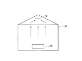
図5に示した熱回収装置10では、金属材料100や加熱炉21から漏れ出す熱が、対流の一現象として常に上昇することを利用する。このため、集熱手段111は高い場所に設置される必要がある。したがって、集熱手段111は、熱間圧延ライン20や製品コイル200の数m上方や、熱間圧延ライン20や製品コイル200が格納される建屋の天井付近に配置される。天井の高さは、20m〜30mの場合もある。例えば図6に示すように、熱間圧延ライン20が格納された建屋50の屋根が三角屋であれば、熱が流れ込みやすい天井の頂上付近に熱回収装置10を設置すれば、効率的に熱を回収できる。図6において、金属材料100は紙面に垂直な方向に搬送される。また、図6に示した矢印は、熱の流れを示す。
The
更に、集熱手段111で集めた比較的高温の空気を更に高温にするために、熱凝集化手段113を集熱手段111と変換手段112の間に配置する。熱凝集化手段113の一部として、例えばヒートポンプを使用できる。
Further, in order to further increase the temperature of the relatively high temperature air collected by the heat collecting means 111, the heat aggregation means 113 is disposed between the heat collecting means 111 and the converting
熱は一般に高温の物体から低温の物体へと流れるが、ヒートポンプを使用することにより、逆の熱の流れを得ることができる。図7は、ヒートポンプの原理を簡単に説明した図である。液体が気体になるときは周囲から熱を奪い、気体から液体になるときは周囲に熱を放出する。この原理を用い、ポンプ61で媒体を圧縮し、蒸発器62で気体にして周囲から熱を奪い、周囲を低温化する。膨張して気体となった媒体は、凝縮器63で液体化し、周囲に熱を供給する。このような仕組みにより、低温側はより低温に、高温側はより高温になる。媒体としては、以前はフロンが使われていたが、最近は代替フロン等が使用されている。ヒートポンプは、一般家庭でも冷蔵庫やエアコンなどに利用されている。
Heat generally flows from a hot object to a cold object, but the reverse heat flow can be obtained by using a heat pump. FIG. 7 is a diagram simply explaining the principle of the heat pump. When the liquid becomes a gas, it takes heat from the surroundings, and when the liquid becomes a liquid, it releases heat to the surroundings. Using this principle, the medium is compressed by the pump 61, gas is made by the
図7に示した蒸発器62に集熱手段111を接続し、凝縮器63に変換手段112を接続することにより、集熱手段111で集めた空気の温度より高い温度を変換手段112が得ることができ、熱電変換の効率が高くなる。
By connecting the heat collecting means 111 to the
熱い空気は上昇する性質をもっているため、熱間圧延ライン20と離れた上方に熱回収装置10を設置することにより、熱を効率的に回収できる。図5に示した熱回収装置10では、熱間圧延ライン20から熱が上昇する広い範囲をカバーできる。このため、下方にデスケーラ等があったとしても、それらに阻害されることなく、熱回収装置10が熱を回収できる。つまり、集熱手段111を金属材料100の直近に設置する場合は、水の飛散がないかなど、周囲の環境が良い場所に限定される。しかし、集熱手段111や変換手段112を熱間圧延ライン20や金属材料100の上方に設置する場合には、そのような周囲の環境に影響されることがない。
Since hot air has the property of rising, heat can be efficiently recovered by installing the
以上に説明したように、第3の実施形態に係る熱回収装置10によれば、熱間圧延ライン20から上昇していく熱を収集することで、熱間圧延ライン20の環境に影響されずに熱を電力に変換することができる。他は、第1の実施形態と実質的に同様であるので、重複した記載を省略する。
As described above, according to the
<変形例>
上記のように熱間圧延ライン20の上方で集められる熱は、集熱手段111により集熱される段階で数十℃である。このため、熱電変換手段11の設置場所が比較的限られる。したがって、集熱手段111、変換手段112及び熱凝集化手段113を、図5に示したようにひとまとまりのユニットとして設置することが、コスト的にも有利でない場合がある。このため、図8に示すように、複数の集熱手段111及び熱凝集化手段113に対して1つの変換手段112を配置して、変換手段112を集約する。これにより、変換手段112の初期コストを抑え、稼働効率を上げる効果が得られる。
<Modification>
As described above, the heat collected above the
図9に示した熱回収装置10は、変換手段112の集約と同様の考え方で、更に熱凝集化手段113を集約したものである。つまり、複数の集熱手段111に対して、1つの熱凝集化手段113が配置される。
The
(第4の実施形態)
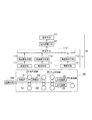
本発明の第4の実施形態に係る熱回収装置10は、図10に示すように、変換手段112により生成される生成電力、及び熱凝集化手段113により消費される消費電力をそれぞれ予測する電力予測手段14と、生成電力と消費電力に基づき、熱回収を行うか否かを判断する判断手段15とを更に備えることが、図9に示した熱回収装置10と異なる。その他の構成については、図9に示した第3の実施形態と同様である。
(Fourth embodiment)
As shown in FIG. 10, the
第3の実施形態に係る熱回収装置10により収集される熱によって効率のよい熱電変換を常に行うことができるとは限らない。これは、熱凝集化手段113が電力を消費するためである。例えば、熱凝集化手段113が図7に示したヒートポンプを有する場合、ポンプ61を駆動する電力が必要である。このため、変換手段112で生成される生成電力と、熱凝集化手段113等で消費する消費電力とを予測し、消費電力の方が生成電力より大きければ、熱回収装置10を駆動しない方がよいことになる。
Efficient thermoelectric conversion cannot always be performed by the heat collected by the
電力予測手段14による電力予測方法には、例えば、過去の消費電力と生成電力の実績をデータベース化し、類似運転状態の指標でそのデータベースから生成電力と消費電力の予測を取り出す方法等を採用可能である。 As a power prediction method by the power prediction means 14, for example, a past power consumption and a record of generated power can be made into a database, and a method of extracting a prediction of generated power and power consumption from the database by using an index of a similar operation state can be adopted. is there.
或いは、図11(a)〜図11(b)に示すような効率曲線を用いて、生成電力と消費電力の関係から熱回収装置10による熱回収の有効性を判断することもできる。図11(a)〜図11(b)は、熱電変換手段11の熱電変換効率とヒートポンプの効率との関係から、生成電力が消費電力より上回る場合に熱回収装置10の稼働が有効であることを示している。効率曲線Xは、熱電変換手段11の熱電変換効率曲線である。
Alternatively, it is possible to determine the effectiveness of heat recovery by the
図11(a)は、ヒートポンプの効率に違いがある場合の例である。ヒートポンプ効率曲線Aの場合は、ヒートポンプに入力電力Paを入れて温度Taを生成しても、熱電変換手段11の出力電力Waは入力電力Paより小さく、熱回収装置10を使用する意味がない。一方、ヒートポンプ効率曲線Bの場合は、温度Tbが生成される場合の入力電力Pbが出力電力Wbより小さく、熱回収装置10の使用が有効である。
FIG. 11A shows an example where there is a difference in the efficiency of the heat pump. In the case of the heat pump efficiency curve A, even if the input power Pa is input to the heat pump to generate the temperature Ta, the output power Wa of the thermoelectric conversion means 11 is smaller than the input power Pa, and there is no point in using the
図11(b)は、ヒートポンプ効率曲線Cのヒートポンプの効率と熱電変換手段11の熱電変換効率との差が、稼働領域で異なる場合を示している。ヒートポンプに入力電力Pcを入れて温度Tcを生成すると、熱電変換手段11の出力電力Wcは入力電力Pcより大きく、熱回収装置10の使用が有効である。温度Tdが生成される場合の入力電力Pdは出力電力Wdより大きいため、熱回収装置10を使用する意味がない。
FIG. 11B shows a case where the difference between the heat pump efficiency of the heat pump efficiency curve C and the thermoelectric conversion efficiency of the thermoelectric conversion means 11 is different in the operating region. When the input power Pc is input to the heat pump to generate the temperature Tc, the output power Wc of the thermoelectric conversion means 11 is larger than the input power Pc, and the use of the
一般に、予め効率曲線がわかっていることが多いため、効率の関係に基づき、熱回収装置10を駆動して熱回収を行うか否かを判断手段15が判断することができる。なお、生成電力が消費電力より大きい場合に熱回収を行うと判断するのではなく、生成電力と消費電力との差が予め設定された一定値以上である場合に、熱回収を行うと判断してもよい。生成電力と消費電力の予測には誤差が伴うものであるから、設定された一定値を用いて、判断に尤度を持たせる意味がある。
In general, since the efficiency curve is often known in advance, the
図10に示した熱回収装置10は、図9に示した熱回収装置10の構成を基本としているが、図5或いは図8に示した熱回収装置10の構成を基本として、電力予測手段14及び判断手段15を付加してもよい。
The
以上に説明したように、本発明の第4の実施形態に係る熱回収装置10によれば、金属材料100の熱の状態や熱回収装置10の消費電力の関係に基づき、熱回収装置10の運転が有効かどうかを判断することができる。これにより、金属材料100や製品コイル200から発生する熱を効率的に回収することができる。他は、第3の実施形態と実質的に同様であるので、重複した記載を省略する。
As described above, according to the
(その他の実施形態)
上記のように、本発明は第1乃至第4の実施形態によって記載したが、この開示の一部をなす論述及び図面はこの発明を限定するものであると理解すべきではない。この開示から当業者には様々な代替実施形態、実施例及び運用技術が明らかとなろう。
(Other embodiments)
As described above, the present invention has been described according to the first to fourth embodiments. However, it should not be understood that the description and drawings constituting a part of this disclosure limit the present invention. From this disclosure, various alternative embodiments, examples and operational techniques will be apparent to those skilled in the art.
既に述べた第1乃至第4の実施形態の説明においては、熱間圧延ライン20が熱間薄板圧延ラインである例を示したが、厚板圧延ライン、形鋼圧延ライン、棒鋼圧延ライン、線材圧延ライン等の高温金属材料を扱う種々の圧延ラインにおいても、圧延ラインで発生する熱を回収する熱回収装置として本発明は適用可能である。
In the description of the first to fourth embodiments already described, an example in which the
このように、本発明はここでは記載していない様々な実施形態等を含むことは勿論である。したがって、本発明の技術的範囲は上記の説明から妥当な特許請求の範囲に係る発明特定事項によってのみ定められるものである。 As described above, the present invention naturally includes various embodiments not described herein. Therefore, the technical scope of the present invention is defined only by the invention specifying matters according to the scope of claims reasonable from the above description.
本発明の熱回収装置は、熱間圧延ラインにより金属材料を加工する製造業に利用可能である。 The heat recovery apparatus of the present invention can be used in a manufacturing industry that processes a metal material by a hot rolling line.
10…熱回収装置
11…熱電変換手段
12…電力貯蔵手段
13…表示手段
14…電力予測手段
15…判断手段
20…熱間圧延ライン
21…加熱炉
22…粗圧延機
23…保熱カバー
24…仕上圧延機
25…水冷装置
26…巻取機
27…テーブルロール
28…上反り矯正装置
30…コイルヤード
50…建屋
61…ポンプ
62…蒸発器
63…凝縮器
100…金属材料
110…熱電素子
111…集熱手段
112…変換手段
113…熱凝集化手段
200…製品コイル
210…コイルカー
DESCRIPTION OF
Claims (6)
前記金属材料で発生する熱を収集する集熱手段、前記集熱手段によって集められた熱の凝集化を行う熱凝集化手段、及び前記熱凝集化手段により凝集化された熱を電力に変換する変換手段を有し、前記熱間圧延ラインにおける前記金属材料の処理によって発生して前記金属材料から大気中に放出された熱を、前記処理による前記金属材料の加熱及び変形加工と並行して大気中で収集し、前記収集された熱を電力に変換する、前記金属材料と大気を介して対向して配置された熱電変換手段と、
前記熱電変換手段により変換された電力を蓄える電力貯蔵手段と、
前記熱電変換手段により生成される生成電力、及び前記熱凝集化手段により消費される消費電力をそれぞれ予測する電力予測手段と、
前記生成電力と前記消費電力に基づき、熱回収を行うか否かを判断する判断手段と
を備えることを特徴とする熱回収装置。 A heat recovery device for a hot rolling line for heating and rolling a metal material,
Heat collecting means for collecting heat generated by the metal material, heat aggregating means for aggregating the heat collected by the heat collecting means, and heat aggregated by the heat aggregating means is converted into electric power Conversion means, and heat generated by the processing of the metallic material in the hot rolling line and released into the atmosphere from the metallic material is heated in parallel with the heating and deformation of the metallic material by the processing. Thermoelectric conversion means disposed in opposition to the metallic material through the atmosphere for collecting the heat and converting the collected heat into electric power;
Power storage means for storing the power converted by the thermoelectric conversion means ;
Power prediction means for predicting the generated power generated by the thermoelectric conversion means and the power consumption consumed by the thermal aggregation means,
A heat recovery apparatus comprising: determination means for determining whether to perform heat recovery based on the generated power and the power consumption .
Priority Applications (3)
| Application Number | Priority Date | Filing Date | Title |
|---|---|---|---|
| JP2009215735A JP5568271B2 (en) | 2009-09-17 | 2009-09-17 | Heat recovery equipment |
| US12/620,724 US20110061703A1 (en) | 2009-09-17 | 2009-11-18 | Heat recovery system for the hot rolling line |
| CN2010101204370A CN102025296A (en) | 2009-09-17 | 2010-01-27 | Heat recovery device |
Applications Claiming Priority (1)
| Application Number | Priority Date | Filing Date | Title |
|---|---|---|---|
| JP2009215735A JP5568271B2 (en) | 2009-09-17 | 2009-09-17 | Heat recovery equipment |
Publications (2)
| Publication Number | Publication Date |
|---|---|
| JP2011062727A JP2011062727A (en) | 2011-03-31 |
| JP5568271B2 true JP5568271B2 (en) | 2014-08-06 |
Family
ID=43729278
Family Applications (1)
| Application Number | Title | Priority Date | Filing Date |
|---|---|---|---|
| JP2009215735A Active JP5568271B2 (en) | 2009-09-17 | 2009-09-17 | Heat recovery equipment |
Country Status (3)
| Country | Link |
|---|---|
| US (1) | US20110061703A1 (en) |
| JP (1) | JP5568271B2 (en) |
| CN (1) | CN102025296A (en) |
Cited By (1)
| Publication number | Priority date | Publication date | Assignee | Title |
|---|---|---|---|---|
| EP3524373A4 (en) * | 2016-10-04 | 2019-08-14 | JFE Steel Corporation | Cutting machine and thermoelectric power generation method |
Families Citing this family (24)
| Publication number | Priority date | Publication date | Assignee | Title |
|---|---|---|---|---|
| WO2011092851A1 (en) * | 2010-01-29 | 2011-08-04 | 東芝三菱電機産業システム株式会社 | Water-injection control device in rolling line, water-injection control method, water-injection control program |
| JP5712772B2 (en) * | 2011-05-02 | 2015-05-07 | 日産自動車株式会社 | Waste heat power generator |
| JP6246998B2 (en) * | 2011-07-27 | 2017-12-13 | Jfeスチール株式会社 | Thermoelectric power generation apparatus and thermoelectric power generation method |
| DE102011082246B4 (en) | 2011-09-07 | 2018-10-04 | Sms Group Gmbh | Arrangement comprising a heat-emitting plant part or product and an apparatus for obtaining electrical energy |
| JP5991131B2 (en) * | 2011-10-06 | 2016-09-14 | Jfeスチール株式会社 | Forged pipe installation line and thermoelectric power generation method using the same |
| JP5920208B2 (en) * | 2011-12-28 | 2016-05-18 | Jfeスチール株式会社 | Continuous casting equipment line and thermoelectric power generation method using the same |
| JP5862300B2 (en) * | 2011-12-30 | 2016-02-16 | Jfeスチール株式会社 | Thermoelectric generation method |
| JP5974883B2 (en) * | 2011-12-30 | 2016-08-23 | Jfeスチール株式会社 | Thermoelectric generation method |
| JP5998983B2 (en) * | 2013-02-25 | 2016-09-28 | Jfeスチール株式会社 | Continuous casting equipment line and thermoelectric power generation method using the same |
| JP6011208B2 (en) * | 2012-09-27 | 2016-10-19 | Jfeスチール株式会社 | Hot rolling equipment line and thermoelectric power generation method using the same |
| KR101686034B1 (en) * | 2012-09-27 | 2016-12-13 | 제이에프이 스틸 가부시키가이샤 | Manufacturing facility line and thermoelectric power generation method |
| KR101686038B1 (en) | 2012-09-27 | 2016-12-13 | 제이에프이 스틸 가부시키가이샤 | Manufacturing facility line and thermoelectric power generation method |
| JP5958433B2 (en) * | 2012-10-12 | 2016-08-02 | Jfeスチール株式会社 | Steel plate manufacturing equipment row for casting and rolling, and thermoelectric power generation method using the same |
| WO2014050127A1 (en) * | 2012-09-27 | 2014-04-03 | Jfeスチール株式会社 | Manufacturing equipment line, and thermoelectric power generation method |
| WO2014156178A1 (en) * | 2013-03-27 | 2014-10-02 | Jfeスチール株式会社 | Thermoelectric power generation device and thermoelectric power generation method |
| WO2014156179A1 (en) * | 2013-03-27 | 2014-10-02 | Jfeスチール株式会社 | Thermoelectric power generation device and thermoelectric power generation method |
| JP5954246B2 (en) * | 2013-04-26 | 2016-07-20 | Jfeスチール株式会社 | Thermoelectric power generation apparatus and thermoelectric power generation method using the same |
| DE112014003717A5 (en) * | 2013-08-12 | 2016-04-28 | Gentherm Gmbh | Electricity generator for converting heat into electrical energy |
| JP6112153B2 (en) * | 2014-09-08 | 2017-04-12 | Jfeスチール株式会社 | Steelworks manufacturing equipment line and thermoelectric power generation method |
| JP6112154B2 (en) * | 2014-09-08 | 2017-04-12 | Jfeスチール株式会社 | Steelworks manufacturing equipment line and thermoelectric power generation method |
| JP6107989B2 (en) * | 2016-02-29 | 2017-04-05 | Jfeスチール株式会社 | Thermoelectric generator |
| KR102245232B1 (en) * | 2019-12-19 | 2021-04-28 | 주식회사 포스코 | Heat recovery apparatus |
| KR102245233B1 (en) * | 2019-12-19 | 2021-04-28 | 주식회사 포스코 | Heat recovery apparatus |
| KR102253518B1 (en) * | 2020-02-21 | 2021-05-18 | 고등기술연구원연구조합 | Thermoelectric generation system for waste heat recovery of casting product |
Family Cites Families (10)
| Publication number | Priority date | Publication date | Assignee | Title |
|---|---|---|---|---|
| US4125122A (en) * | 1975-08-11 | 1978-11-14 | Stachurski John Z O | Direct energy conversion device |
| JPS57194710U (en) * | 1981-06-08 | 1982-12-10 | ||
| JP4101935B2 (en) * | 1998-07-07 | 2008-06-18 | 東芝三菱電機産業システム株式会社 | Rolling mill cooling device |
| US6636016B2 (en) * | 2000-10-16 | 2003-10-21 | Toshiba Battery Co., Ltd. | Battery pack and backup power supply device utilizing the battery pack |
| JP2003079054A (en) * | 2001-08-31 | 2003-03-14 | Sanyo Electric Co Ltd | Solar power generation system having storage battery |
| GB2437996B (en) * | 2004-05-19 | 2009-02-11 | Central Res Inst Elect | Thermoelectric conversion system and efficiency improving method of thermoelectric conversion system |
| CN1707935B (en) * | 2004-06-11 | 2010-05-12 | 珍通科技股份有限公司 | Self-supply electric energy method and system for portable electronic equipment |
| JP4367362B2 (en) * | 2005-03-24 | 2009-11-18 | 住友金属工業株式会社 | Waste heat recovery method and cooling bed |
| JP5198455B2 (en) * | 2006-09-28 | 2013-05-15 | ローズマウント インコーポレイテッド | Improved industrial thermoelectric generator |
| JP2008098403A (en) * | 2006-10-12 | 2008-04-24 | Ihi Corp | Thermoelectric conversion device, and heat treatment apparatus |
-
2009
- 2009-09-17 JP JP2009215735A patent/JP5568271B2/en active Active
- 2009-11-18 US US12/620,724 patent/US20110061703A1/en not_active Abandoned
-
2010
- 2010-01-27 CN CN2010101204370A patent/CN102025296A/en active Pending
Cited By (2)
| Publication number | Priority date | Publication date | Assignee | Title |
|---|---|---|---|---|
| EP3524373A4 (en) * | 2016-10-04 | 2019-08-14 | JFE Steel Corporation | Cutting machine and thermoelectric power generation method |
| US11040409B2 (en) | 2016-10-04 | 2021-06-22 | Jfe Steel Corporation | Cutting machine and thermoelectric power generation method |
Also Published As
| Publication number | Publication date |
|---|---|
| JP2011062727A (en) | 2011-03-31 |
| CN102025296A (en) | 2011-04-20 |
| US20110061703A1 (en) | 2011-03-17 |
Similar Documents
| Publication | Publication Date | Title |
|---|---|---|
| JP5568271B2 (en) | Heat recovery equipment | |
| CN102667336B (en) | For the method that recovers energy in smelting technique equipment and the smelting technique equipment based on thermocouple | |
| JP5920208B2 (en) | Continuous casting equipment line and thermoelectric power generation method using the same | |
| JP5832698B2 (en) | Thermoelectric power generation apparatus and thermoelectric power generation method | |
| Liu et al. | An Internet of Things-enabled model-based approach to improving the energy efficiency of aluminum die casting processes | |
| JP5832697B2 (en) | Thermoelectric power generation apparatus and thermoelectric power generation method using the same | |
| WO2014050127A1 (en) | Manufacturing equipment line, and thermoelectric power generation method | |
| JP6217776B2 (en) | Manufacturing equipment column and thermoelectric power generation method | |
| JP6311805B2 (en) | Steelworks manufacturing equipment line and thermoelectric power generation method | |
| JP6011208B2 (en) | Hot rolling equipment line and thermoelectric power generation method using the same | |
| JP5958433B2 (en) | Steel plate manufacturing equipment row for casting and rolling, and thermoelectric power generation method using the same | |
| JP6112154B2 (en) | Steelworks manufacturing equipment line and thermoelectric power generation method | |
| JP5998983B2 (en) | Continuous casting equipment line and thermoelectric power generation method using the same | |
| Abuheiba et al. | Benefit FOA FY2015-Solid State Magnetocaloric Air Conditioner | |
| Lan et al. | Effect of operation parameters on waste heat recovery on the coke surface of periodic graphitization furnaces | |
| CN210464081U (en) | Waste heat recovery utilizes device for forging shop | |
| Wheeler et al. | End-of-Life Strategies For HVAC Systems: Planning for Failure. | |
| Thoelen et al. | Waste heat recovery in steel industry for steam production to feed carbon capture process | |
| Gopalakrishnan et al. | Energy consumption modelling and benchmarking in continuous galvanising lines | |
| KR20150053270A (en) | Manufacturing facility line and thermoelectric power generation method | |
| JP2014073524A (en) | Forge-welded tube equipment line and thermoelectric generation method using the same | |
| Gopalakrishnan et al. | Analysis of Compressed Air and Process Heating Systems-A Case Study from Automotive Parts Manufacturer in Mexico | |
| Valenti | More from the mill |
Legal Events
| Date | Code | Title | Description |
|---|---|---|---|
| A621 | Written request for application examination |
Free format text: JAPANESE INTERMEDIATE CODE: A621 Effective date: 20111207 |
|
| A977 | Report on retrieval |
Free format text: JAPANESE INTERMEDIATE CODE: A971007 Effective date: 20130626 |
|
| A131 | Notification of reasons for refusal |
Free format text: JAPANESE INTERMEDIATE CODE: A131 Effective date: 20130716 |
|
| A521 | Request for written amendment filed |
Free format text: JAPANESE INTERMEDIATE CODE: A523 Effective date: 20130827 |
|
| A131 | Notification of reasons for refusal |
Free format text: JAPANESE INTERMEDIATE CODE: A131 Effective date: 20131203 |
|
| A521 | Request for written amendment filed |
Free format text: JAPANESE INTERMEDIATE CODE: A523 Effective date: 20140107 |
|
| TRDD | Decision of grant or rejection written | ||
| A01 | Written decision to grant a patent or to grant a registration (utility model) |
Free format text: JAPANESE INTERMEDIATE CODE: A01 Effective date: 20140610 |
|
| A61 | First payment of annual fees (during grant procedure) |
Free format text: JAPANESE INTERMEDIATE CODE: A61 Effective date: 20140623 |
|
| R150 | Certificate of patent or registration of utility model |
Ref document number: 5568271 Country of ref document: JP Free format text: JAPANESE INTERMEDIATE CODE: R150 |
|
| R250 | Receipt of annual fees |
Free format text: JAPANESE INTERMEDIATE CODE: R250 |
|
| R250 | Receipt of annual fees |
Free format text: JAPANESE INTERMEDIATE CODE: R250 |
|
| R250 | Receipt of annual fees |
Free format text: JAPANESE INTERMEDIATE CODE: R250 |
|
| R250 | Receipt of annual fees |
Free format text: JAPANESE INTERMEDIATE CODE: R250 |
|
| R250 | Receipt of annual fees |
Free format text: JAPANESE INTERMEDIATE CODE: R250 |
|
| R250 | Receipt of annual fees |
Free format text: JAPANESE INTERMEDIATE CODE: R250 |
|
| R250 | Receipt of annual fees |
Free format text: JAPANESE INTERMEDIATE CODE: R250 |