JP5568151B2 - Blood pressure pulse wave inspection device - Google Patents
Blood pressure pulse wave inspection device Download PDFInfo
- Publication number
- JP5568151B2 JP5568151B2 JP2013046506A JP2013046506A JP5568151B2 JP 5568151 B2 JP5568151 B2 JP 5568151B2 JP 2013046506 A JP2013046506 A JP 2013046506A JP 2013046506 A JP2013046506 A JP 2013046506A JP 5568151 B2 JP5568151 B2 JP 5568151B2
- Authority
- JP
- Japan
- Prior art keywords
- cuff
- blood pressure
- pulse wave
- pressure
- control unit
- Prior art date
- Legal status (The legal status is an assumption and is not a legal conclusion. Google has not performed a legal analysis and makes no representation as to the accuracy of the status listed.)
- Active
Links
Images


Description
本発明は、例えば血圧や脈波等の生体情報を活用して動脈硬化の検査に使用する指標(以下「動脈硬化度」という)を導出する血圧脈波検査装置に関する。 The present invention relates to a blood pressure pulse wave inspection apparatus for deriving an index (hereinafter referred to as “arteriosclerosis degree”) to be used for inspection of arteriosclerosis by utilizing biological information such as blood pressure and pulse wave.
動脈硬化の検査には、例えば、下肢血管の血流障害の検査と、動脈伸展性の検査とがある。これらの検査に用いられる血圧脈波検査装置は、血圧や脈波といった生体情報を計測して、動脈硬化度を導出することができる。以下、動脈硬化度について幾つかの例を挙げて説明する。なお、各指標の計測手法はここで説明するものだけに限定されず、様々な手法で計測することができる。 The arteriosclerosis test includes, for example, a test for blood flow disorder in the lower limb blood vessels and a test for arterial extensibility. The blood pressure pulse wave inspection apparatus used for these examinations can measure biological information such as blood pressure and pulse wave to derive the degree of arteriosclerosis. Hereinafter, some examples of the degree of arteriosclerosis will be described. In addition, the measuring method of each index is not limited to the one described here, and can be measured by various methods.
下肢血管の血流障害の検査には、例えばABI(Ankle Brachial Index)が用いられる。 For example, ABI (Ankle Brachial Index) is used for the examination of blood flow disorders in the lower limb blood vessels.
ABIは、足首の収縮期血圧の値を上腕の収縮期血圧の値で除算して得られる値であり、API又はABPIと呼ばれることもある。ABIに類似した指標として、TBI(Toe Pressure Index)と呼ばれるものもある。TBIは、足趾(足の指)の収縮期血圧の値を上腕に収縮期血圧の値で除算して得られる値であり、TPI又はTBPIと呼ばれることもある。 ABI is a value obtained by dividing the value of the systolic blood pressure of the ankle by the value of the systolic blood pressure of the upper arm, and is sometimes called API or ABPI. As an index similar to ABI, there is an index called TBI (Toe Pressure Index). The TBI is a value obtained by dividing the value of the systolic blood pressure of the toes (toes) by the value of the systolic blood pressure in the upper arm, and is sometimes called TPI or TBPI.
動脈伸展性の検査には、例えば、大動脈PWV(Pulse Wave Velocity)(例えば、非特許文献1参照)やbaPWV(brachial-ankle Pulse Wave Velocity:上腕−足首間PWV)(例えば、非特許文献2参照)、CAVI(Cardio-Ankle Vascular Index)(例えば、非特許文献3参照)等が用いられる。 For the examination of arterial extensibility, for example, aortic PWV (Pulse Wave Velocity) (see, for example, Non-Patent Document 1) and baPWV (brachial-ankle Pulse Wave Velocity: upper arm-ankle PWV) (for example, see Non-Patent Document 2) ), CAVI (Cardio-Ankle Vascular Index) (for example, see Non-Patent Document 3) and the like.
PWVとは、脈波伝播速度であり、血管上の異なる2点間の距離の値を2点での脈波の時間差の値で除算して得られる、速度の単位を持つ値である。脈波の計測には、例えば、空気伝導式、光電式、空気袋式、アモルファス式、トノメトリ式等、各種方式の脈波センサが用いられ得る。また、PWV計測の対象部位としては、弾性動脈である大動脈が採用されることがあり、大動脈で計測されたPWVを大動脈PWVという。大動脈PWVの計測方法としては、主に2つのものがある。 PWV is a pulse wave velocity, and is a value having a velocity unit obtained by dividing the value of the distance between two different points on the blood vessel by the value of the time difference between the pulse waves at the two points. For example, various types of pulse wave sensors such as an air conduction type, a photoelectric type, an air bag type, an amorphous type, and a tonometry type may be used for measuring the pulse wave. Further, the aorta, which is an elastic artery, may be adopted as a target site for PWV measurement, and the PWV measured in the aorta is referred to as the aorta PWV. There are mainly two methods for measuring the aortic PWV.
一方の大動脈PWV計測方法では、例えば次の式(1)により大動脈PWVを求める。
PWV=(b+c−a)/ΔT ・・・(1)
ここで、ΔTは、頸動脈部での脈波立ち上がり部と大腿動脈部での脈波立ち上がり部との時間差であり、aは、胸骨上窩から頸動脈部までの距離であり、bは、胸骨上窩から臍部までの距離であり、cは、臍部から大腿動脈部までの距離である。
In one aorta PWV measurement method, for example, the aorta PWV is obtained by the following equation (1).
PWV = (b + c−a) / ΔT (1)
Here, ΔT is the time difference between the pulse wave rising portion at the carotid artery portion and the pulse wave rising portion at the femoral artery portion, a is the distance from the suprasternal fossa to the carotid artery portion, and b is C is the distance from the umbilicus to the femoral artery.
他方の大動脈PWV計測方法では、例えば次の式(2)により大動脈PWVを求める。
PWV=D×1.3/(ΔT+Tc) ・・・(2)
ここで、ΔTは、頸動脈部での脈波立ち上がり部と大腿動脈部での脈波立ち上がり部との時間差であり、Tcは、心II音(大動脈弁閉鎖の際に生じる心音)の開始から頸動脈部での脈波の切痕部(ディクロティックノッチ)までの時間であり、Dは、心II音を計測する心音マイクが置かれた第II肋間胸骨右縁から大腿動脈部までの直線距離であり、1.3は解剖学的補正値である。
In the other aorta PWV measurement method, for example, the aorta PWV is obtained by the following equation (2).
PWV = D × 1.3 / (ΔT + Tc) (2)
Here, ΔT is a time difference between the pulse wave rising portion in the carotid artery portion and the pulse wave rising portion in the femoral artery portion, and Tc is from the start of the heart II sound (heart sound generated when the aortic valve is closed). It is the time to the notch (dichroic notch) of the pulse wave in the carotid artery, and D is a straight line from the right edge of the second intercostal sternum where the heart sound microphone for measuring heart II sound is placed to the femoral artery It is a distance, and 1.3 is an anatomical correction value.
baPWVは、例えば次の式(3)により求められる。
baPWV=(La−Lb)/Tba ・・・(3)
ここで、Tbaは、カフを用いてそれぞれ計測される、上腕での脈波立ち上がり部と足首での脈波立ち上がり部との時間差であり、Laは、大動脈弁口部から足首までの距離であり、Lbは、大動脈弁口部から上腕までの距離である。
For example, baPWV is obtained by the following equation (3).
baPWV = (La−Lb) / Tba (3)
Here, Tba is the time difference between the pulse wave rising part at the upper arm and the pulse wave rising part at the ankle, each measured using a cuff, and La is the distance from the aortic valve opening to the ankle. , Lb is the distance from the aortic valve opening to the upper arm.
また、CAVIの計測では、上腕と足首(又は膝窩)とにカフを装着して血圧及び脈波の計測をすると共に、胸骨に心音マイクを装着して心音を計測する。CAVIは、例えば次の式(4)により求められる。

以上の説明から分かるように、動脈伸展性検査に関連する動脈硬化度の算出には、脈波立ち上がり部や切痕部といった特徴点の検出が必要である。また、ここで説明していない他の動脈硬化度導出手法においても何らかの特徴点の検出が必要である。よって、特徴点の検出精度は、導出される動脈硬化度の信頼性に大きな影響を与える。 As can be seen from the above description, detection of feature points such as a pulse wave rising portion and a notch portion is necessary for calculation of the degree of arteriosclerosis related to the arterial extensibility test. In addition, in other arteriosclerosis derivation methods not described here, it is necessary to detect some feature points. Therefore, the detection accuracy of feature points has a great influence on the reliability of the derived degree of arteriosclerosis.
しかしながら、脈波は変動し易く正確な検出が容易でない。特に空気袋式、つまりカフを測定対象部位に巻回し内部の空気袋の圧力変動により脈波を測定する方式の場合は、比較的簡便に測定可能である反面、外的要因の影響を受け易い。したがって、動脈硬化度の信頼性に一定の限界があった。 However, pulse waves tend to fluctuate and are not easily detected accurately. In particular, in the case of the air bag type, that is, the method of measuring the pulse wave by the pressure fluctuation of the air bag inside by wrapping the cuff around the measurement target part, it can be measured relatively easily, but it is easily affected by external factors. . Therefore, there is a certain limit to the reliability of the degree of arteriosclerosis.
本発明は、かかる点に鑑みてなされたもので、脈波の検出結果から求められる動脈硬化度の信頼性を向上させることができる血圧脈波検査装置を提供することを目的とする。 The present invention has been made in view of such a point, and an object thereof is to provide a blood pressure pulse wave examination apparatus capable of improving the reliability of the degree of arteriosclerosis obtained from the detection result of pulse waves.
本発明の血圧脈波検査装置は、被検者の複数部位に巻回可能な複数のカフと、前記複数のカフを用いて被検者の脈波を計測する計測部と、被検者の脈波を計測するとき、前記複数のカフの各々についてカフ圧の制御を行う圧力制御部と、を含む血圧脈波計測部と、計測した脈波の特徴部を検出し、検出した特徴部に基づいて被検者の動脈硬化度を導出する導出部と、を有し、前記血圧脈波計測部は、前記少なくとも一のカフを非加圧状態のカフ圧から加圧し、その加圧中に前記少なくとも一のカフを用いて被検者の血圧を計測し、計測した被検者の収縮期血圧に応じて決まる当該収縮期血圧以上のカフ圧にてその加圧を停止し、その停止時のカフ圧が保持された状態で前記少なくとも一のカフを用いて被検者の脈波を計測する、構成を採る。 A blood pressure pulse wave inspection device of the present invention includes a plurality of cuffs that can be wound around a plurality of parts of a subject , a measurement unit that measures the pulse waves of the subject using the plurality of cuffs , When measuring a pulse wave, a blood pressure pulse wave measurement unit including a pressure control unit that controls cuff pressure for each of the plurality of cuffs, and a feature part of the measured pulse wave are detected, and the detected feature part is A blood pressure pulse wave measurement unit that pressurizes the at least one cuff from a cuff pressure in a non-pressurized state during the pressurization. The blood pressure of the subject is measured using the at least one cuff, and the pressurization is stopped at a cuff pressure equal to or higher than the systolic blood pressure determined according to the measured systolic blood pressure of the subject. In this state, the pulse wave of the subject is measured using the at least one cuff while the cuff pressure is maintained .
本発明によれば、脈波の検出結果から求められる動脈硬化度の信頼性を向上させることができる。 ADVANTAGE OF THE INVENTION According to this invention, the reliability of the arteriosclerosis degree calculated | required from the detection result of a pulse wave can be improved.
以下、本発明の実施の形態について、図面を用いて詳細に説明する。 Hereinafter, embodiments of the present invention will be described in detail with reference to the drawings.
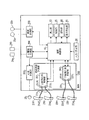
図1は、本発明の一実施の形態に係る血圧脈波検査装置の構成を示す図である。 FIG. 1 is a diagram showing a configuration of a blood pressure pulse wave inspection apparatus according to an embodiment of the present invention.
図1において、血圧脈波検査装置は、演算制御部10、表示部70、記録部75、保存部80、音声発生部85、入力/指示部90、上腕用計測制御部201、下肢用計測制御部202、心音計測部203、心電図計測部204及び脈波計測部205を、本体の筐体内に収容してなるものである。上腕用計測制御部201には、右上腕用カフ21R及び左上腕用カフ21Lがそれぞれホース21hを介して接続され、下肢用計測制御部202には、右足首用カフ22R及び左足首用カフ22Lがそれぞれホース22hを介して接続され、心音計測部203には心音マイク23が接続され、心電図計測部204には、四肢用心電電極部24a及び胸部用心電電極部24bが接続され、脈波計測部205には、アモルファス式脈波センサ25a、25bが接続されている。上腕用計測制御部201及び下肢用計測制御部202は、血圧脈波計測部200を構成する。
In FIG. 1, the blood pressure pulse wave examination apparatus includes an
演算制御部10は、CPU(Central Processing Unit)、ROM(Read Only Memory)、RAM(Random Access Memory)、各種インタフェース等を有するコンピュータである。演算制御部10は、ROMに記憶された制御プログラムをCPUで実行することにより、以下説明する装置全体の動作を制御する。
The
また、演算制御部10は、各種の生体情報の計測を行う上腕用計測制御部201、下肢用計測制御部202、心音計測部203、心電図計測部204及び脈波計測部205(以下「各生体情報計測部」という)を制御する。
The
また、演算制御部10は、各生体情報計測部から供給された生体情報を受信する。そして、受信した生体情報を、画面に表示する必要があるときには表示用データに編集又は変換した上で表示部70に、レポート用の用紙に印字する必要があるときには印字用データに編集又は変換した上で記録部75に、出力する。また、演算制御部10は適宜、受信した生体情報を保存部80に保存したり、保存された生体情報を読み出したりする。
Further, the
また、導出部としての演算制御部10は、各生体情報計測部から受信した生体情報の波形分析を行う。波形分析では、波形における特徴部(区分点)の検出等を行う。特徴部としては、例えば、心II音の開始部、上腕での脈波の立ち上がり部、足首での脈波の立ち上がり部、上腕での脈波の切痕部、等が挙げられる。演算制御部10は、この分析結果と、受信した生体情報により示された数値(例えば血圧)とに基づいて、動脈硬化度の算出を行う。算出され得る動脈硬化度及びその算出式等については、既に説明したため、ここでは省略する。
In addition, the
また、演算制御部10は、この動脈硬化度及び波形分析結果も、生体情報と同様に、画面に表示する必要があるときには表示用データに編集又は変換した上で表示部70に、レポート用の用紙に印字する必要があるときには印字用データに編集又は変換した上で記録部75に、出力する。また、演算制御部10は適宜、動脈硬化度及び分析結果を保存部80に保存したり、保存されたそれらの情報を読み出したりする。
The
また、演算制御部10は、ユーザによる操作を支援するための音声ガイダンスが必要なときには、ガイダンス用データを音声発生部85に出力する。
Further, the
また、演算制御部10は、ユーザの操作による入力や指示の内容を入力/指示部90から受信し、受信内容に従って、各生体情報計測部や表示部70、記録部75、保存部80、音声発生部85の機能に関連する設定を行ったり、それぞれの動作の開始や停止を制御したりする。
Further, the
表示部70は、例えばLCD(Liquid Crystal Display)等の表示画面を有する表示装置であり、演算制御部10から表示用データとして入力された生体情報、波形分析結果及び動脈硬化度を画面に表示する。
The
記録部75は、給紙機構や印字用ヘッド等を主要構成として有し、演算制御部10から印字用データとして入力された生体情報、波形分析結果及び動脈硬化度を用紙に印字する。
The
保存部80は、ハードディスクドライブや書き込み可能な光ディスクドライブ、不揮発性メモリ等により構成され、演算制御部10からの情報の保持が可能である。
The
音声発生部85は、スピーカ等を主要構成として有し、演算制御部10から入力されたガイダンス用データ又は報知音出力指示信号に従って、ガイダンス音声又は報知音を生成する。
The sound generation unit 85 has a speaker or the like as a main component, and generates a guidance sound or a notification sound according to guidance data or a notification sound output instruction signal input from the
入力/指示部90は、キーボードやマウス、ボタン、タッチパネル等から構成され、ユーザの操作による入力や指示を可能にする。ユーザによる入力や指示の内容は演算制御部10に通知される。
The input /
脈波計測部205は、アモルファス式の脈波計測手段である。脈波計測部205は、被検者に適切に装着されたアモルファス式脈波センサ25a、25bにより検出された被検者の脈波信号を演算制御部10に供給することにより、脈波の計測を行う。脈波の計測は、生体情報取得装置の電源投入時に開始されてもよいし、演算制御部10からの脈波計測開始指示の受信時に開始されてもよい。脈波計測部205による脈波の計測は、演算制御部10で大動脈PWVを求める場合に好適に用いられ、この場合、アモルファス式脈波センサ25a、25bの一方は、被検者の頸動脈部に装着され、他方は、被検者の大腿動脈部又は膝部に装着される。
The pulse
心電図計測部204は、被検者に装着された四肢用心電電極部24a及び胸部用心電電極部24bにより検出された心電図信号を演算制御部10に供給することにより、心電図の計測を行う。四肢用心電電極部24aは、典型的には、右手首、左手首、右足首及び左足首にそれぞれ装着される4つの心電電極からなる。両足首用の心電電極に関しては、両足首への装着が右足首用カフ22R及び左足首用カフ22Lにより妨げられないように形成されていることが好ましい。また、胸部用心電電極部25bは、典型的には、胸部の6箇所にそれぞれ装着される6つの心電電極からなる。
The
心音計測部203は、被検者に装着された心音マイク23により検出された心音信号を演算制御部10に供給することにより、心音の計測を行う。
The heart
計測部及び圧力制御部としての血圧脈波計測部200は、本実施の形態では、上肢用計測制御部201と下肢用計測制御部202とを独立に設けてなるものであるが、上肢用計測制御部201と下肢用計測制御部202と一体化してなるものであってもよい。血圧脈波計測部200は、オシロメトリック式の血圧脈波計測手段であり、血圧計測手段及び脈波計測手段の両方の機能を有する。
In the present embodiment, the blood pressure pulse
上腕用計測制御部201は、2つの圧力センサ211R、211Lを有する他に、ポンプ、排気弁、CPU、メモリ及びフィルタを有する。メモリには、ポンプ、排気弁、右上腕用カフ21R及び左上腕用カフ21Lによる血圧計測及び脈波計測を制御するプログラムと、この制御に関連する設定情報とが記憶されている。上腕用計測制御部201は、CPUによりプログラムを設定情報に従って実行する。上腕用計測制御部201は、ポンプ及び排気弁を用いて、ホース21hを介して右上腕用カフ21R及び左上腕用カフ21Lのゴム嚢21aR、21aLに空気を導入することにより右上腕用カフ21R及び左上腕用カフ21Lの加圧を行う一方、ゴム嚢21aR、21aLから空気を排出することにより、右上腕用カフ21R及び左上腕用カフ21Lの減圧を行う。右上腕用カフ21Rは、使用時に右上腕に巻回されるカフを指し、左上腕用カフ21Lは、使用時に左上腕に巻回されるカフを指す。
The upper arm
また、上腕用計測制御部201は、カフ加圧後、右上腕用カフ21R及び左上腕用21Lのカフ圧を保持(つまり、ゴム嚢21aR、21aLに対する吸排気を行わない)しつつ、右上腕用カフ21R及び左上腕用21Lのカフ圧の振動を脈波信号として圧力センサ211R、211Lで検出し、検出した脈波信号を演算制御部10に供給することにより、脈波の計測を行う。上腕用計測制御部201は、脈波信号をフィルタにより濾波した上で演算制御部10に出力する。脈波信号は演算制御部10において特徴部検出のための波形分析に用いられるため、正確な波形分析を期すために、脈波の位相成分を崩すことなく濾波を行うことができるタイプのディジタルフィルタを用いることが好ましい。
In addition, the upper arm
また、上腕用計測制御部201は、カフ減圧中又はカフ加圧中に、血圧の計測を行う。
The upper arm
カフ減圧中の血圧計測の場合、上腕用計測制御部201は、右上腕用カフ21R及び左上腕用カフ21Lのカフ圧の振動を圧力センサ211R、211Lにより検出しながら、振動振幅の増大が最も顕著なカフ圧を収縮期血圧として検出すると共に、振動振幅の減少が最も顕著なカフ圧を拡張期血圧として検出して、検出した収縮期血圧及び拡張期血圧をそれぞれ示す血圧信号を演算制御部10に供給することにより、血圧の計測を行う。この場合において、上腕用計測制御部201は、右上腕用カフ21Rのみを用いた右側の血圧の計測と、左上腕用カフ21Lのみを用いた左側の血圧の計測とを別々に行うことができる。
In the case of blood pressure measurement during cuff decompression, the upper arm
カフ加圧中の血圧計測の場合、上腕用計測制御部201は、右上腕用カフ21R及び左上腕用カフ21Lのカフ圧の振動を圧力センサ211R、211Lにより検出しながら、振動振幅の増大が最も顕著なカフ圧を拡張期血圧として検出すると共に、振動振幅の減少が最も顕著なカフ圧を収縮期血圧として検出して、検出した拡張期血圧及び収縮期血圧をそれぞれ示す血圧信号を演算制御部10に供給することにより、血圧の計測を行う。この場合において、上腕用計測制御部201は、右上腕用カフRのみを用いた右側の血圧の計測と、左上腕用カフ21Lのみを用いた左側の血圧の計測とを別々に行うことができる。
In the case of blood pressure measurement during cuff pressurization, the upper arm
なお、振動するカフ圧からの収縮期血圧及び拡張期血圧の検出は、上腕用計測制御部201の代わりに演算制御部10にて行うこともできる。
Note that the systolic blood pressure and the diastolic blood pressure can be detected from the vibrating cuff pressure by the
下肢用計測制御部202は、2つの圧力センサ221R、221Lを有する他に、ポンプ、排気弁、CPU、メモリ及びフィルタを有する。メモリには、ポンプ、排気弁、右足首用カフ22R及び左足首用カフ22Lによる血圧計測及び脈波計測を制御するプログラムと、この制御に関連する設定情報とが記憶されている。下肢用計測制御部202は、CPUによりプログラムを設定情報に従って実行する。下肢用計測制御部202は、ポンプ及び排気弁を用いて、ホース22hを介して右足首用カフ22R及び左足首用カフ22Lのゴム嚢22aR、22aLに空気を導入することにより右足首用カフ22R及び左足首用カフ22Lの加圧を行う一方、ゴム嚢22aR、22aLから空気を排出することにより、右足首用カフ22R及び左足首用カフ22Lの減圧を行う。右足首用カフ22Rは、使用時に右足首に巻回されるカフを指し、左足首用カフ22Lは、使用時に左足首に巻回されるカフを指す。
The lower limb
また、下肢用計測制御部202は、カフ加圧後、右足首用カフ22R及び左足首用22Lのカフ圧を保持(つまり、ゴム嚢22aR、22aLに対する吸排気を行わない)しつつ、右足首用カフ22R及び左足首用22Lのカフ圧の振動を脈波信号として圧力センサ221R、221Lで検出し、検出した脈波信号を演算制御部10に供給することにより、脈波の計測を行う。下肢用計測制御部202は、脈波信号をフィルタにより濾波した上で演算制御部10に出力する。脈波信号は演算制御部10において特徴部検出のための波形分析に用いられるため、正確な波形分析を期すために、脈波の位相成分を崩すことなく濾波を行うことができるタイプのディジタルフィルタを用いることが好ましい。
In addition, the
また、下肢用計測制御部202は、カフ減圧中又はカフ加圧中に、血圧の計測を行う。
The lower limb
カフ減圧中の血圧の計測の場合、下肢用計測制御部202は、右足首用カフ22R及び左足首用カフ22Lのカフ圧の振動を圧力センサ221R、221Lにより検出しながら、振動振幅の増大が最も顕著なカフ圧を収縮期血圧として検出すると共に、振動振幅の減少が最も顕著なカフ圧を拡張期血圧として検出して、検出した収縮期血圧及び拡張期血圧をそれぞれ示す血圧信号を演算制御部10に供給することにより、血圧の計測を行う。この場合において、下肢用計測制御部202は、右足首用カフ22Rのみを用いた右側の血圧の計測と、左足首用カフ22Lのみを用いた左側の血圧の計測とを別々に行うことができる。
In the case of blood pressure measurement during cuff decompression, the lower limb
カフ加圧中の血圧の計測の場合、下肢用計測制御部202は、右足首用カフ22R及び左足首用カフ22Lのカフ圧の振動を圧力センサ221R、221Lにより検出しながら、振動振幅の増大が最も顕著なカフ圧を拡張期血圧として検出すると共に、振動振幅の減少が最も顕著なカフ圧を収縮期血圧として検出して、検出した拡張期血圧及び収縮期血圧をそれぞれ示す血圧信号を演算制御部10に供給することにより、血圧の計測を行う。この場合において、下肢用計測制御部202は、右足首用カフ22Rのみを用いた右側の血圧の計測と、左足首用カフ22Lのみを用いた左側の血圧の計測とを別々に行うことができる。
In the case of measuring blood pressure during cuff pressurization, the lower limb
なお、振動するカフ圧からの収縮期血圧及び拡張期血圧の検出は、下肢用計測制御部202の代わりに演算制御部10にて行うこともできる。
The systolic blood pressure and the diastolic blood pressure can be detected from the vibrating cuff pressure by the
次いで、上記構成を有する血圧脈波検査装置において実行される動脈硬化度算出処理について、図2を用いて説明する。ここでは、CAVIを算出する処理の一例を挙げて説明するが、その算出手順は種々変更して実施してもよい。算出手順等を適宜変更することにより他の動脈硬化度の算出も可能である。 Next, arteriosclerosis degree calculation processing executed in the blood pressure pulse wave examination apparatus having the above configuration will be described with reference to FIG. Here, an example of processing for calculating CAVI will be described, but the calculation procedure may be variously changed. Other degrees of arteriosclerosis can be calculated by appropriately changing the calculation procedure and the like.
動脈硬化度算出処理の事前準備として、まずユーザ(医師、検査技師等)は、被検者の識別情報や身長、血管長等の必要情報を入力/指示部90を用いて入力する。入力された必要情報は、演算制御部10により保存部80に取り込まれる。またユーザは、右上腕用カフ21R、左上腕用カフ21L、右足首用カフ22R、左足首用カフ22L、心音マイク23、四肢用心電電極部24a及び胸部用心電電極部24bをそれぞれ、仰臥位の被検者の所定位置に装着する。このとき各カフと被検者の心臓との高さが略同じとなるようにする。そして、被検者の安静状態を確認した後、ユーザは、入力/指示部90を用いて開始操作を行う。これによりその旨の指示信号が演算制御部10に入力され、演算制御部10は動脈硬化度算出処理の全体制御を開始する。初期状態では、各生体情報計測部はそれぞれの生体情報の計測を停止しているものとする。
As advance preparation for the degree of arteriosclerosis calculation, a user (physician, laboratory technician, etc.) first inputs necessary information such as identification information, height, and blood vessel length of the subject using the input /
まず、ステップS100では、演算制御部10は、心電図計測のための動作を開始させる信号を心電図計測部204に出力し、これにより心電図計測部204は、被検者の心電図を計測し、その結果を示す心電図信号を生成する。これに並行して、演算制御部10は、心音計測のための動作を開始させる信号を心音計測部203に出力し、これに従って心音計測部203は、被検者の心音を計測し、その結果を示す心音信号を生成する。心音信号は、演算制御部10により保存部80に取り込まれる。さらに、これらに並行して、演算制御部10は、脈波計測のための動作を開始させる信号を上腕用計測制御部201及び下肢用計測制御部202に出力し、これに従って上腕用計測制御部201及び下肢用計測制御部202は脈波の計測を行い、それぞれの結果を示す脈波信号を生成する。生成された心電図信号、心音信号及び脈波信号は、演算制御部10により保存部80に取り込まれる。そして、演算制御部10は、保存部80に取り込まれた信号を読み出して、波形分析を行う。前述の通り、波形分析では、波形における特徴部、例えば、心II音の開始部、上腕での脈波の立ち上がり部、足首での脈波の立ち上がり部、上腕での脈波の切痕部等を検出する。なお、脈波計測には、図3を参照して後述する一連の処理が含まれており、この一連の処理が完了すると、脈波計測は終了し波形分析も終了する(ステップS200)。
First, in step S100, the
そして、演算制御部10は、ステップS300において、ステップS200終了時のカフ圧の状態を変えずに一定期間(例えば10秒間)だけ待機した後、ステップS400に進む。
In step S300, the
ステップS400では、演算制御部10は、被検者の右半身(右上腕及び右足首)の血圧計測のための動作を開始させる信号を上腕用計測制御部201及び下肢用計測制御部202に出力し、これに従って上腕用計測制御部201及び下肢用計測制御部202は、右上腕用カフ21R及び右足首用カフ22Rをそれぞれ用いて血圧の計測を行う。
In step S400, the
具体的には、上腕用計測制御部201は右上腕用カフ21Rを、下肢用計測制御部202は右足首用カフ22Rを、測定対象の収縮期血圧よりも高い適当な所定値まで加圧する。カフ加圧が完了すると、上腕用計測制御部201は右上腕用カフ21Rを、下肢用計測制御部202は右足首用カフ22Rを、徐々に減圧する。カフ減圧中、上腕用計測制御部201は、右上腕の収縮期血圧及び拡張期血圧を計測し、下肢用計測制御部202は、右足首の収縮期血圧及び拡張期血圧を計測する。血圧計測後、右上腕用カフ21R及び右足首用カフ22Rのカフ圧が非加圧状態に相当する値に戻ると、上腕用計測制御部201及び下肢用計測制御部202は、計測したそれぞれの血圧値を示す血圧信号を演算制御部10に出力する。血圧信号は演算制御部10により保存部80に取り込まれる。なお、ここではカフ減圧中の血圧計測を例に挙げたが、代わりにカフ加圧中の血圧計測を行ってもよいし、カフ減圧中の血圧計測とカフ加圧中の血圧計測とを両方行ってもよい。
Specifically, the upper arm
ステップS500では、演算制御部10は、被検者の左半身(左上腕及び左足首)の血圧計測のための動作を開始させる信号を上腕用計測制御部201及び下肢用計測制御部202に出力し、これに従って上腕用計測制御部201及び下肢用計測制御部202は、左上腕用カフ21L及び左足首用カフ22Lをそれぞれ用いて血圧の計測を行う。なお、左側の血圧計測の具体的手順に関しては、上記右側の血圧計測の手順において加減圧の対象カフを右上腕及び右足首用のカフ21R、22Rから左上腕及び左足首用のカフ21L、22Lに替えることにより、右側血圧計測と同様に実現することができる。
In step S500, the
そして、ステップS600では、演算制御部10は、この分析結果と、受信した生体情報により示された数値、例えば血圧とに基づいて、CAVIの算出を行う。
In step S600, the
このようにして得られたCAVIは、必要に応じて、表示部70により画面に表示され又は記録部75により記録紙に印字される。
The CAVI thus obtained is displayed on the screen by the
ここで、上記ステップS100で実行される脈波計測のための一連の処理について、図3を用いて説明する。 Here, a series of processing for pulse wave measurement executed in step S100 will be described with reference to FIG.
まず、上腕用計測制御部201及び下肢用計測制御部202は、全てのカフ21R、21L、22R、22Lの加圧を同時に開始する(ステップS101)。全てのカフ21R、21L、22R、22Lの加圧は、カフ圧が一般的な拡張期血圧以下で、脈波計測に適した圧(ここでは50mmHg)に到達するまで継続され(ステップS102)、カフ圧が50mmHgに到達すると、上腕用計測制御部201及び下肢用計測制御部202は、左上腕用のカフ21Lを除くカフ21R、22R、22Lの加圧を停止し、それらのカフ圧を保持する(ステップS103)。左上腕用カフ21Lの加圧は継続される。
First, the upper arm
そして、上腕用計測制御部201は、加圧中の左上腕用カフ21Lを用いて、拡張期血圧を計測し、そして収縮期血圧を計測する(ステップS104)。
The upper arm
継続加圧は、血管が閉塞するよう計測された収縮期血圧と同圧もしくはそれ以上の圧となるようになるまで(ここでは収縮期血圧よりもカフ圧が20mmHgだけ高くなるまで)行われ(ステップS105)、その後、上腕用計測制御部201は、左上腕用カフ21Lの加圧を停止し、そのカフ圧を保持する(ステップS106)。
The continuous pressurization is performed until the pressure becomes equal to or higher than the systolic blood pressure measured so that the blood vessel is occluded (in this case, until the cuff pressure becomes higher by 20 mmHg than the systolic blood pressure) ( After that, the upper arm
このように、血圧の計測を行いながら加圧を継続するため、所望のカフ圧(ここでは収縮期血圧+20mmHgとしているが、収縮期血圧と同圧の場合や収縮期血圧+40mmHgの場合もある)で確実に加圧を停止させることができる。 Thus, in order to continue pressurization while measuring blood pressure, a desired cuff pressure (here, systolic blood pressure + 20 mmHg is used, but it may be the same pressure as systolic blood pressure or systolic blood pressure + 40 mmHg). Thus, pressurization can be surely stopped.
なお、血圧の計測は、前述したステップS400及びS500においても行われるが、ステップS104で行った血圧計測の結果も血圧信号として取り込み、これをCAVIの算出に活用してもよい。 The blood pressure measurement is also performed in steps S400 and S500 described above, but the result of the blood pressure measurement performed in step S104 may also be taken in as a blood pressure signal and used for calculation of CAVI.
そして、ステップS107では、上腕用計測制御部201及び下肢用計測制御部202は、カフ圧がそれぞれ保持された状態にある全てのカフ21R、21L、22R、22Lを用いて、脈波の計測を行う。
In step S107, the upper arm
一定期間(例えば約20秒間)にわたって脈波の計測を行った後、上腕用計測制御部201及び下肢用計測制御部202は、全てのカフ21R、21L、22R、22Lの減圧を開始する(ステップS108)。これらのカフ圧が非加圧状態に相当する値まで戻ると(ステップS109)、上腕用計測制御部201及び下肢用計測制御部202は全てのカフ21R、21L、22R、22Lの減圧を停止する(ステップS110)。
After measuring the pulse wave for a certain period (for example, about 20 seconds), the upper arm
図2及び図3を参照して説明した処理を行うと、例えば図4に示すような計測結果が得られる。ここでは、左上腕用カフ21Lのカフ圧を140mmHgに保持した場合を例にとっている。 When the processing described with reference to FIGS. 2 and 3 is performed, a measurement result as shown in FIG. 4 is obtained, for example. Here, a case where the cuff pressure of the left upper arm cuff 21L is held at 140 mmHg is taken as an example.
左上腕以外の部位では、被検者の血管に全く作用せず血管を圧迫しない圧力(ここでは50mmHg)にカフ圧が保持されているため、計測した脈波の波形は一定の品質を有しているものの、脈波本来の波形を鮮鋭に反映したものではない。一方、左上腕では、被検者の血管を閉塞させる圧力(ここでは140mmHg)にカフ圧が保持されているため、計測した脈波の波形は脈波本来の波形を鮮鋭に反映した非常に良好な品質の波形となっている。例えば、領域aにある切痕部は鮮鋭に出現していないが、領域bにある切痕部は鮮鋭に出現している。これは、左上腕では末梢血管からの脈反射の影響を受けない状態で脈波計測が行われていることに起因する。 Since the cuff pressure is maintained at a pressure (here, 50 mmHg) that does not act on the blood vessel of the subject at all and other than the left upper arm, the measured pulse wave waveform has a certain quality. However, it does not sharply reflect the original waveform of the pulse wave. On the other hand, in the upper left arm, the cuff pressure is held at a pressure (in this case, 140 mmHg) that occludes the blood vessel of the subject, so the measured pulse wave waveform is very good reflecting the original waveform of the pulse wave sharply. The waveform is of good quality. For example, the notch portion in the region a does not appear sharply, but the notch portion in the region b appears sharply. This is because the pulse wave measurement is performed in the left upper arm without being affected by the pulse reflection from the peripheral blood vessel.
したがって、本実施の形態によれば、切痕部のタイミングを正確に検出することができ、ひいては算出されるCAVIの信頼性を向上させることができる。 Therefore, according to the present embodiment, it is possible to accurately detect the timing of the notch portion, and thus improve the reliability of the calculated CAVI.
また、血管を閉塞させるような収縮期血圧以上のカフ圧の下での脈波計測は、血管を圧迫しない拡張期血圧未満のカフ圧の下での脈波計測と異なり、身体への影響が大きい。このため、本実施の形態では、全ての部位でなく1箇所でのみ高圧を保持して脈波計測を行う。よって、身体への影響を最小限に抑えつつ、正確に特徴部を検出することができる。 In addition, pulse wave measurement under cuff pressure higher than systolic blood pressure that occludes blood vessels is different from pulse wave measurement under cuff pressure less than diastolic blood pressure that does not compress blood vessels, and has an effect on the body. large. For this reason, in the present embodiment, the pulse wave measurement is performed while maintaining the high pressure only at one place instead of all the places. Therefore, it is possible to accurately detect the feature portion while minimizing the influence on the body.
また、上腕への動脈は大静脈弓部で分岐したものであることから、左上腕でのみ高圧を保持して脈波の計測を行うことにより、大動脈弓部での脈波に非常に似た脈波の波形を得ることができ、切痕部等の特徴部を一段と正確に検出することができる。 Also, because the artery to the upper arm is branched at the vena cava arch, it is very similar to the pulse wave at the aortic arch by holding the high pressure only at the left upper arm and measuring the pulse wave A waveform of a pulse wave can be obtained, and a characteristic part such as a notch can be detected more accurately.
なお、本実施の形態では、一部のカフのみのカフ圧を高圧まで加圧させる目的は、脈波の切痕部、すなわちディクロティックノッチの正確な検出であるが、他の特徴部の正確な検出を目的としてもよい。例えば、脈波のパーカッションウェーブのピークとタイダルウェーブのピークとの正確な検出を目的とすることができる。 In this embodiment, the purpose of increasing the cuff pressure of only a part of the cuffs to a high pressure is to accurately detect the notch portion of the pulse wave, that is, the dichroic notch. It may be aimed at accurate detection. For example, it is possible to accurately detect the peak of the percussion wave of the pulse wave and the peak of the tidal wave.
また、上記ステップS100での脈波計測について、図3を用いて具体的な手順の一例を説明したが、脈波計測手順は上記のものだけに限定されない。以下、図5、図6及び図7を用いて3つの変形例について説明する。 Moreover, although an example of the specific procedure was demonstrated about the pulse wave measurement in the said step S100 using FIG. 3, the pulse wave measurement procedure is not limited only to the above. Hereinafter, three modifications will be described with reference to FIGS. 5, 6, and 7.
まず、図5を用いて第1の変形例について説明する。この例では、カフ加圧中だけでなくカフ減圧中も血圧計測を行う。図3に示す手順と対比すると、図5の例は、ステップS108とステップS109との間にステップS111を追加した点で相違する。 First, a first modification will be described with reference to FIG. In this example, blood pressure is measured not only during cuff pressurization but also during cuff decompression. In contrast to the procedure shown in FIG. 3, the example of FIG. 5 is different in that step S111 is added between step S108 and step S109.
ステップS111では、上腕用計測制御部201は、減圧中の全てのカフ21R、21L、22R、22Lのうち左上腕用カフ21Lのみを用いて、収縮期血圧を計測し、そして拡張期血圧を計測する。ここでの計測結果を示す血圧信号は、演算制御部10により保存部80に取り込まれ、CAVIの算出に活用される。
In step S111, the upper arm
血圧の計測は、前述したステップS400、S500、S104において行われるが、上記第1の変形例では、ステップS111で行った血圧計測の結果も血圧信号として取り込むことができる。よって、血圧の計測精度を向上させることができ、算出されるCAVIの信頼性のさらなる向上につながる。 Blood pressure is measured in steps S400, S500, and S104 described above. In the first modification, the blood pressure measurement result obtained in step S111 can also be captured as a blood pressure signal. Therefore, blood pressure measurement accuracy can be improved, leading to further improvement in the reliability of the calculated CAVI.
続いて、図6を用いて第2の変形例について説明する。図3の例では左上腕用カフ21Lのみを高圧まで加圧したのに対し、この例では、左上腕用カフ21Lに加えて右上腕用カフ21Rを高圧まで加圧する。図3よりも類似する図5に示す手順と対比すると、図6の例は、ステップS103、S104、S106、S111をステップS112、S113、S114、S115に置換した点で相違する。
Subsequently, a second modification will be described with reference to FIG. In the example of FIG. 3, only the left upper arm cuff 21L is pressurized to a high pressure, whereas in this example, the upper
ステップS112では、上腕用計測制御部201及び下肢用計測制御部202は、カフ圧が50mmHgに到達すると、上腕用のカフ21R、21Lを除く下肢用のカフ22R、22Lの加圧を停止し、それらのカフ圧を保持する。上腕用のカフ21R、21Lの加圧は継続される。
In step S112, when the cuff pressure reaches 50 mmHg, the upper arm
また、ステップS113では、上腕用計測制御部201は、加圧中の上腕用のカフ21R、21Lを用いて拡張期血圧及び収縮期血圧の計測を左右の上腕について同時に行う。
In step S113, the upper arm
また、ステップS114では、上腕用計測制御部201は、上腕用のカフ21R、21Lの加圧を停止し、そのカフ圧を保持する。
In step S114, the upper arm
このように、血圧の計測を行いながら加圧を継続するため、所望のカフ圧(ここでは収縮期血圧+20mmHg)で確実に加圧を停止させることができる。 Thus, since pressurization is continued while measuring blood pressure, pressurization can be reliably stopped at a desired cuff pressure (here, systolic blood pressure + 20 mmHg).
なお、血圧の計測は、前述したステップS400及びS500においても行われるが、ステップS113で行った血圧計測の結果も血圧信号として取り込み、これをCAVIの算出に活用してもよい。 Blood pressure measurement is also performed in steps S400 and S500 described above, but the result of blood pressure measurement performed in step S113 may also be taken in as a blood pressure signal and used for calculation of CAVI.
また、ステップS115では、上腕用計測制御部201は、減圧中の全てのカフ21R、21L、22R、22Lのうち上腕用のカフ21R、21Lのみを用いて、左右両腕の収縮期血圧を計測し、そして左右両腕の拡張期血圧を計測する。
In step S115, the upper arm
ステップS115での計測結果を示す血圧信号は、演算制御部10により保存部80に取り込まれ、CAVIの算出に活用される。
The blood pressure signal indicating the measurement result in step S115 is taken into the
血圧の計測は、前述したステップS400、S500、S113において行われるが、上記第2の変形例によれば、ステップS115で行った血圧計測の結果も血圧信号として取り込むことができる。しかもステップS115では左右両腕の血圧計測結果を得ることができる。よって、血圧の計測精度を一層向上させることができ、算出されるCAVIの信頼性のさらなる向上につながる。 The blood pressure is measured in steps S400, S500, and S113 described above. According to the second modification, the blood pressure measurement result performed in step S115 can also be captured as a blood pressure signal. In addition, in step S115, blood pressure measurement results for the left and right arms can be obtained. Therefore, blood pressure measurement accuracy can be further improved, leading to further improvement in the reliability of the calculated CAVI.
さらに、図6に示す手順を図2に示す手順に組み合わせて実施する場合は、図2におけるステップS300において一定期間待機した後、上腕用計測制御部201を動作させず、下肢用のカフ22R、22Lを用いた血圧の計測を同時に行うよう下肢用計測制御部202を動作させてもよい。これにより、上半身の血圧計測と下半身の血圧計測とをそれぞれ同時に行うことができるため、被検者の身体への負荷を増大させることなく血圧計測の工程を減らすことができる。
Further, when the procedure shown in FIG. 6 is combined with the procedure shown in FIG. 2, after waiting for a certain period of time in step S300 in FIG. 2, the upper arm
続いて、図7を用いて第3の変形例について説明する。図3の例では無条件に左上腕用カフ21Lを高圧まで加圧したのに対し、この例では、左上腕用カフ21Lを高圧まで加圧するための条件を適用する。すなわち、第3の変形例は、図3に示す手順においてステップS103をステップS116、S117、S118、S119、S120に置換し、所定の条件を満たした場合にはステップS104、S105、S106、S107を実行し、所定の条件を満たさなかった場合にはステップS104、S105、S106、S107をスキップする。 Subsequently, a third modification will be described with reference to FIG. In the example of FIG. 3, the left upper arm cuff 21L is unconditionally pressurized to a high pressure, whereas in this example, the condition for pressurizing the left upper arm cuff 21L to a high pressure is applied. That is, in the third modification, step S103 is replaced with steps S116, S117, S118, S119, and S120 in the procedure shown in FIG. 3, and steps S104, S105, S106, and S107 are performed when a predetermined condition is satisfied. Step S104, S105, S106, S107 are skipped if the predetermined condition is not satisfied.
ステップS116では、上腕用計測制御部201及び下肢用計測制御部202は、カフ圧が50mmHgに到達すると、全てのカフ21R、21L、22R、22Lの加圧を停止し、それらのカフ圧を保持する。
In step S116, when the cuff pressure reaches 50 mmHg, the upper arm
ステップS117では、上腕用計測制御部201及び下肢用計測制御部202は、カフ圧がそれぞれ保持された状態にある全てのカフ21R、21L、22R、22Lを用いて、脈波の計測を行う。一定期間(例えば約20秒間)にわたって脈波の計測を行った後、その測定結果を示す脈波信号が、演算制御部10により保存部80に取り込まれる。
In step S117, the upper-arm
ステップS118では、演算制御部10は、前述したステップS100と同様の波形分析を行う。
In step S118, the
ステップS119では、演算制御部10は、上記波形分析において脈波の切痕部の検出が失敗したか否かを判断する。切痕部検出に失敗したという条件を満たした場合は、カフ圧をさらに加圧して脈波計測を行う必要があるため、左上腕用カフ21Lのみの加圧を再開する(ステップS120)。換言すれば、ステップS120では、ステップS116で行われた一次加圧に対する二次加圧が行われる。ステップS120の後は、図3のステップS104に進む。
In step S119, the
一方、切痕部検出に成功した場合は、カフ圧をこれ以上加圧することにより身体への負荷を回避するため、図3のステップS104、S105、S106、S107をスキップして、ステップS108に進む。 On the other hand, if the cut portion is successfully detected, steps S104, S105, S106, and S107 in FIG. 3 are skipped to proceed to step S108 in order to avoid overloading the body by further increasing the cuff pressure. .
このように、第3の変形例によれば、不必要な身体への負荷を回避することができる。 Thus, according to the third modification, unnecessary load on the body can be avoided.
以上、本発明の実施の形態について説明した。なお、以上の説明は本発明の好適な実施の形態の例証であり、本発明の範囲はこれに限定されない。つまり、上記装置の構成及び使用時の動作についての説明は一例であり、本発明の範囲においてこれらの例に対する様々な変更や追加が可能であることは明らかである。 The embodiment of the present invention has been described above. The above description is an illustration of a preferred embodiment of the present invention, and the scope of the present invention is not limited to this. That is, the description of the configuration of the apparatus and the operation at the time of use is an example, and it is obvious that various modifications and additions to these examples are possible within the scope of the present invention.
10 演算制御部
21R 右上腕用カフ
21L 左上腕用カフ
21aR、21aL、22aR、22aL ゴム嚢
22R 右足首用カフ
22L 左足首用カフ
21h、22h ホース
23 心音マイク
24a 四肢用心電電極部
24b 胸部用心電電極部
200 血圧脈波計測部
201 上腕用計測制御部
202 下肢用計測制御部
203 心音計測部
204 心電図計測部
211R、211L、221R、221L 圧力センサ
10
Claims (4)
前記複数のカフを用いて被検者の脈波を計測する計測部と、被検者の脈波を計測するとき、前記複数のカフの各々についてカフ圧の制御を行う圧力制御部と、を含む血圧脈波計測部と、
計測した脈波の特徴部を検出し、検出した特徴部に基づいて被検者の動脈硬化度を導出する導出部と、
を有し、
前記血圧脈波計測部は、前記少なくとも一のカフを非加圧状態のカフ圧から加圧し、その加圧中に前記少なくとも一のカフを用いて被検者の血圧を計測し、計測した被検者の収縮期血圧に応じて決まる当該収縮期血圧以上のカフ圧にてその加圧を停止し、その停止時のカフ圧が保持された状態で前記少なくとも一のカフを用いて被検者の脈波を計測する、
ことを特徴とする血圧脈波検査装置。 Multiple cuffs that can be wound around multiple locations on the subject;
A measurement unit that measures the pulse wave of the subject using the plurality of cuffs, and a pressure control unit that controls cuff pressure for each of the plurality of cuffs when measuring the pulse wave of the subject. Including a blood pressure pulse wave measurement unit,
A derivation unit that detects a characteristic part of the measured pulse wave and derives a degree of arteriosclerosis of the subject based on the detected characteristic part;
Have
The blood pressure pulse wave measurement unit pressurizes the at least one cuff from an unpressurized cuff pressure, measures the blood pressure of the subject using the at least one cuff during the pressurization, and measures the measured subject. The cuff pressure is stopped at a cuff pressure equal to or higher than the systolic blood pressure determined according to the systolic blood pressure of the examiner, and the subject is used with the at least one cuff in a state in which the cuff pressure at the stop is held. Measuring the pulse wave of
A blood pressure pulse wave inspection device characterized by the above.
ことを特徴とする請求項1記載の血圧脈波検査装置。The blood pressure pulse wave inspection apparatus according to claim 1.
ことを特徴とする請求項1又は請求項2記載の血圧脈波検査装置。The blood pressure pulse wave examination apparatus according to claim 1 or 2, wherein
ことを特徴とする請求項2記載の血圧脈波検査装置。The blood pressure pulse wave inspection apparatus according to claim 2.
Priority Applications (1)
| Application Number | Priority Date | Filing Date | Title |
|---|---|---|---|
| JP2013046506A JP5568151B2 (en) | 2013-03-08 | 2013-03-08 | Blood pressure pulse wave inspection device |
Applications Claiming Priority (1)
| Application Number | Priority Date | Filing Date | Title |
|---|---|---|---|
| JP2013046506A JP5568151B2 (en) | 2013-03-08 | 2013-03-08 | Blood pressure pulse wave inspection device |
Related Parent Applications (1)
| Application Number | Title | Priority Date | Filing Date |
|---|---|---|---|
| JP2008081218A Division JP5530073B2 (en) | 2008-03-26 | 2008-03-26 | Blood pressure pulse wave inspection device |
Publications (2)
| Publication Number | Publication Date |
|---|---|
| JP2013144124A JP2013144124A (en) | 2013-07-25 |
| JP5568151B2 true JP5568151B2 (en) | 2014-08-06 |
Family
ID=49040292
Family Applications (1)
| Application Number | Title | Priority Date | Filing Date |
|---|---|---|---|
| JP2013046506A Active JP5568151B2 (en) | 2013-03-08 | 2013-03-08 | Blood pressure pulse wave inspection device |
Country Status (1)
| Country | Link |
|---|---|
| JP (1) | JP5568151B2 (en) |
Cited By (1)
| Publication number | Priority date | Publication date | Assignee | Title |
|---|---|---|---|---|
| JP2013144125A (en) * | 2013-03-08 | 2013-07-25 | Fukuda Denshi Co Ltd | Blood pressure/pulse wave examining apparatus |
Family Cites Families (6)
| Publication number | Priority date | Publication date | Assignee | Title |
|---|---|---|---|---|
| JP3590613B2 (en) * | 2002-01-10 | 2004-11-17 | コーリンメディカルテクノロジー株式会社 | Amplitude increase index calculation device and arteriosclerosis test device |
| JP3697241B2 (en) * | 2002-12-20 | 2005-09-21 | コーリンメディカルテクノロジー株式会社 | Atherosclerosis evaluation device |
| JP4576114B2 (en) * | 2003-12-08 | 2010-11-04 | フクダ電子株式会社 | Biological measuring device |
| TWI275381B (en) * | 2005-04-11 | 2007-03-11 | Dailycare Biomedical Inc | An apparatus and method for measurement of pulse wave base on blood pressure method |
| JP5179707B2 (en) * | 2005-06-17 | 2013-04-10 | フクダ電子株式会社 | Report of vascular elasticity index over time, generation method thereof, and biological information output device |
| JP4363442B2 (en) * | 2006-12-20 | 2009-11-11 | オムロンヘルスケア株式会社 | Atherosclerosis inspection device |
-
2013
- 2013-03-08 JP JP2013046506A patent/JP5568151B2/en active Active
Cited By (1)
| Publication number | Priority date | Publication date | Assignee | Title |
|---|---|---|---|---|
| JP2013144125A (en) * | 2013-03-08 | 2013-07-25 | Fukuda Denshi Co Ltd | Blood pressure/pulse wave examining apparatus |
Also Published As
| Publication number | Publication date |
|---|---|
| JP2013144124A (en) | 2013-07-25 |
Similar Documents
| Publication | Publication Date | Title |
|---|---|---|
| JP5644325B2 (en) | Blood pressure information measuring device and method for calculating an index of arteriosclerosis in the device | |
| US7029449B2 (en) | Arteriosclerosis inspecting apparatus | |
| EP1715429A1 (en) | Device and method for outputting bioinformation and bioinformation report | |
| EP1227754A1 (en) | Apparatus and method for measuring an induced perturbation to determine a physiological parameter | |
| KR20150082401A (en) | Improved blood pressure monitor and method | |
| JP3970697B2 (en) | Biological information processing device | |
| JP5530073B2 (en) | Blood pressure pulse wave inspection device | |
| JP2004121616A (en) | Automatic diagnostic apparatus | |
| JP5255771B2 (en) | Biological information processing apparatus and biological information processing method | |
| JP5752162B2 (en) | Blood pressure pulse wave inspection device | |
| JP5568151B2 (en) | Blood pressure pulse wave inspection device | |
| JP6276912B2 (en) | Biological information test result report, biological information processing apparatus, and biological information processing program | |
| KR101918577B1 (en) | Blood Pressure Meter And Method For Measuring Blood Pressure Using The Same | |
| JP4576114B2 (en) | Biological measuring device | |
| JP5236881B2 (en) | Blood pressure pulse wave inspection device and blood pressure pulse wave inspection method | |
| JP6862093B2 (en) | Blood pressure pulse wave measuring device | |
| JP6393797B2 (en) | Biological information processing apparatus and biological information processing program | |
| JP2005278965A (en) | Cardiac function evaluation device | |
| JP5006509B2 (en) | Pulse wave velocity measurement method for measuring pulse wave velocity in a pulse wave velocity measuring device | |
| JP6430161B2 (en) | Central blood pressure measuring device and central blood pressure measuring method | |
| JP6109514B2 (en) | Biological information processing device | |
| JP6112810B2 (en) | Biological information processing apparatus and display method in biological information processing apparatus | |
| JP6013111B2 (en) | Biological information processing device | |
| JP2023086338A (en) | Blood pressure pulse wave measuring device and blood pressure pulse wave measuring method | |
| JP4490727B2 (en) | Pulse wave transit time measuring apparatus and method of using the same |
Legal Events
| Date | Code | Title | Description |
|---|---|---|---|
| A521 | Request for written amendment filed |
Free format text: JAPANESE INTERMEDIATE CODE: A523 Effective date: 20130422 |
|
| A977 | Report on retrieval |
Free format text: JAPANESE INTERMEDIATE CODE: A971007 Effective date: 20140428 |
|
| TRDD | Decision of grant or rejection written | ||
| A01 | Written decision to grant a patent or to grant a registration (utility model) |
Free format text: JAPANESE INTERMEDIATE CODE: A01 Effective date: 20140527 |
|
| A61 | First payment of annual fees (during grant procedure) |
Free format text: JAPANESE INTERMEDIATE CODE: A61 Effective date: 20140620 |
|
| R150 | Certificate of patent or registration of utility model |
Ref document number: 5568151 Country of ref document: JP Free format text: JAPANESE INTERMEDIATE CODE: R150 |
|
| R250 | Receipt of annual fees |
Free format text: JAPANESE INTERMEDIATE CODE: R250 |
|
| R250 | Receipt of annual fees |
Free format text: JAPANESE INTERMEDIATE CODE: R250 |
|
| R250 | Receipt of annual fees |
Free format text: JAPANESE INTERMEDIATE CODE: R250 |
|
| R250 | Receipt of annual fees |
Free format text: JAPANESE INTERMEDIATE CODE: R250 |
|
| R250 | Receipt of annual fees |
Free format text: JAPANESE INTERMEDIATE CODE: R250 |
|
| R250 | Receipt of annual fees |
Free format text: JAPANESE INTERMEDIATE CODE: R250 |
|
| R250 | Receipt of annual fees |
Free format text: JAPANESE INTERMEDIATE CODE: R250 |