JP5564384B2 - Image generation program, imaging apparatus, imaging system, and image generation method - Google Patents

Image generation program, imaging apparatus, imaging system, and image generation method Download PDF

Info

Publication number
JP5564384B2
JP5564384B2 JP2010217531A JP2010217531A JP5564384B2 JP 5564384 B2 JP5564384 B2 JP 5564384B2 JP 2010217531 A JP2010217531 A JP 2010217531A JP 2010217531 A JP2010217531 A JP 2010217531A JP 5564384 B2 JP5564384 B2 JP 5564384B2
Authority
JP
Japan
Prior art keywords
face
image
imaging unit
imaging
unit
Prior art date
Legal status (The legal status is an assumption and is not a legal conclusion. Google has not performed a legal analysis and makes no representation as to the accuracy of the status listed.)
Active
Application number
JP2010217531A
Other languages
Japanese (ja)
Other versions
JP2012074878A (en
Inventor
祐亮 秋房
直子 森
美鈴 吉田
亜沙子 鍵田
隆薫 山根
Current Assignee (The listed assignees may be inaccurate. Google has not performed a legal analysis and makes no representation or warranty as to the accuracy of the list.)
Nintendo Co Ltd
Original Assignee
Nintendo Co Ltd
Priority date (The priority date is an assumption and is not a legal conclusion. Google has not performed a legal analysis and makes no representation as to the accuracy of the date listed.)
Filing date
Publication date
Application filed by Nintendo Co Ltd filed Critical Nintendo Co Ltd
Priority to JP2010217531A priority Critical patent/JP5564384B2/en
Priority to US13/247,348 priority patent/US8648924B2/en
Publication of JP2012074878A publication Critical patent/JP2012074878A/en
Application granted granted Critical
Publication of JP5564384B2 publication Critical patent/JP5564384B2/en
Active legal-status Critical Current
Anticipated expiration legal-status Critical

Links

Images

Classifications

    • HELECTRICITY
    • H04ELECTRIC COMMUNICATION TECHNIQUE
    • H04NPICTORIAL COMMUNICATION, e.g. TELEVISION
    • H04N1/00Scanning, transmission or reproduction of documents or the like, e.g. facsimile transmission; Details thereof
    • H04N1/00127Connection or combination of a still picture apparatus with another apparatus, e.g. for storage, processing or transmission of still picture signals or of information associated with a still picture
    • H04N1/00132Connection or combination of a still picture apparatus with another apparatus, e.g. for storage, processing or transmission of still picture signals or of information associated with a still picture in a digital photofinishing system, i.e. a system where digital photographic images undergo typical photofinishing processing, e.g. printing ordering
    • H04N1/00183Photography assistance, e.g. displaying suggestions to the user
    • GPHYSICS
    • G06COMPUTING; CALCULATING OR COUNTING
    • G06TIMAGE DATA PROCESSING OR GENERATION, IN GENERAL
    • G06T5/00Image enhancement or restoration
    • G06T5/50Image enhancement or restoration by the use of more than one image, e.g. averaging, subtraction
    • GPHYSICS
    • G06COMPUTING; CALCULATING OR COUNTING
    • G06TIMAGE DATA PROCESSING OR GENERATION, IN GENERAL
    • G06T2207/00Indexing scheme for image analysis or image enhancement
    • G06T2207/20Special algorithmic details
    • G06T2207/20212Image combination
    • G06T2207/20221Image fusion; Image merging
    • GPHYSICS
    • G06COMPUTING; CALCULATING OR COUNTING
    • G06TIMAGE DATA PROCESSING OR GENERATION, IN GENERAL
    • G06T2207/00Indexing scheme for image analysis or image enhancement
    • G06T2207/30Subject of image; Context of image processing
    • G06T2207/30196Human being; Person
    • G06T2207/30201Face
    • GPHYSICS
    • G06COMPUTING; CALCULATING OR COUNTING
    • G06VIMAGE OR VIDEO RECOGNITION OR UNDERSTANDING
    • G06V40/00Recognition of biometric, human-related or animal-related patterns in image or video data
    • G06V40/10Human or animal bodies, e.g. vehicle occupants or pedestrians; Body parts, e.g. hands
    • G06V40/16Human faces, e.g. facial parts, sketches or expressions
    • G06V40/161Detection; Localisation; Normalisation
    • HELECTRICITY
    • H04ELECTRIC COMMUNICATION TECHNIQUE
    • H04NPICTORIAL COMMUNICATION, e.g. TELEVISION
    • H04N2101/00Still video cameras

Landscapes

  • Engineering & Computer Science (AREA)
  • Multimedia (AREA)
  • Signal Processing (AREA)
  • Physics & Mathematics (AREA)
  • General Physics & Mathematics (AREA)
  • Theoretical Computer Science (AREA)
  • Processing Or Creating Images (AREA)
  • Television Signal Processing For Recording (AREA)
  • Studio Devices (AREA)
  • Studio Circuits (AREA)

Description

本発明は、撮像装置のコンピュータに実行させる画像生成プログラム、撮像装置、撮像システム、及び画像生成方法に関し、より特定的には、人物等の顔を撮像して得られた撮像画像に対して顔認識機能を用いて画像処理を行う撮像装置のコンピュータに実行させる画像生成プログラム、撮像装置、撮像システム、及び画像生成方法に関する。   The present invention relates to an image generation program, an image pickup apparatus, an image pickup system, and an image generation method that are executed by a computer of an image pickup apparatus, and more specifically, a face for a picked-up image obtained by picking up a face of a person or the like. The present invention relates to an image generation program, an imaging apparatus, an imaging system, and an image generation method that are executed by a computer of an imaging apparatus that performs image processing using a recognition function.

近年、撮像装置は多機能化しており、人物の顔を撮像して得られた撮像画像から人物の顔の特徴点を抽出して顔を認識する機能を備えた撮像装置が存在する。例えば特許文献1には、撮像画像から被写体である人物の顔に対応する顔領域を検出して、その顔領域に対して、ユーザが要求する処理を行うことができる電子カメラが開示されている。   In recent years, imaging devices have become multifunctional, and there are imaging devices that have a function of recognizing a face by extracting feature points of the person's face from a captured image obtained by imaging a person's face. For example, Patent Document 1 discloses an electronic camera that can detect a face area corresponding to the face of a person who is a subject from a captured image and perform processing requested by the user on the face area. .

特開2007−280291号公報JP 2007-280291 A

ところで、特許文献1に記載の電子カメラが備える例えば顔の肌色を補正するといった一般的な画像処理機能だけでなく、撮影が楽しくなるような興趣性の高い撮像画像が得られる画像処理機能が求められている。   By the way, not only a general image processing function such as correcting the skin color of the face provided in the electronic camera described in Patent Document 1, but also an image processing function capable of obtaining a highly interesting captured image that makes shooting fun is desired. It has been.

それ故に、本発明の目的は、興趣性が高い撮像画像が得られる画像生成プログラム、撮像装置、撮像システム、及び画像生成方法を提供することである。   Therefore, an object of the present invention is to provide an image generation program, an imaging apparatus, an imaging system, and an image generation method capable of obtaining a captured image with high interest.

本発明に係る画像生成プログラムは、撮像装置のコンピュータに実行させる画像生成プログラムであって、コンピュータを、撮像画像取得手段、顔画像取得手段、及び顔合成画像生成手段として機能させる。撮像画像取得手段は、少なくとも1つの撮像部によりリアルタイムに撮像画像を取得する。顔画像取得手段は、撮像画像取得手段によって取得された撮像画像に含まれる複数の顔領域から第1顔領域を検出し、第1顔領域の少なくとも一部の画像を第1顔画像として取得する。顔合成画像生成手段は、複数の顔領域のうちの第1顔領域とは異なる第2顔領域の少なくとも一部を第1顔画像に差し替えた顔合成画像を生成する。   An image generation program according to the present invention is an image generation program to be executed by a computer of an imaging apparatus, and causes the computer to function as a captured image acquisition unit, a face image acquisition unit, and a face composite image generation unit. The captured image acquisition unit acquires the captured image in real time by at least one imaging unit. The face image acquisition unit detects a first face region from a plurality of face regions included in the captured image acquired by the captured image acquisition unit, and acquires at least a partial image of the first face region as the first face image. . The face composite image generation means generates a face composite image in which at least a part of the second face area different from the first face area among the plurality of face areas is replaced with the first face image.

この構成では、例えば、撮像部によって被写体としての2人の顔がリアルタイムに撮像されて、1人目の顔全体に相当する第1顔領域の少なくとも一部を表す第1顔画像が顔画像取得手段によって取得される。そして、2人目の顔全体に相当する第2顔領域の少なくとも一部を第1顔画像に差し替えた顔合成画像が顔合成画像生成手段によって生成される。その結果、例えばある人物の顔全体を別の人物の顔に差し替えた顔合成画像や、ある人物の顔の一部(例えば目)を別の人物の顔の一部(同じく目)に差し替えた顔合成画像が得られる。すなわち、被写体としての複数人の顔をそのまま再現した撮像画像ではなく、複数人の顔を合成した興趣性が高い撮像画像を得ることが可能になる。   In this configuration, for example, two faces as subjects are imaged in real time by the imaging unit, and a first face image representing at least a part of the first face area corresponding to the entire first face is a face image acquisition unit. Obtained by. Then, the face composite image is generated by replacing the at least part of the second face area corresponding to the entire face of the second person with the first face image. As a result, for example, a face composite image in which the entire face of one person is replaced with the face of another person, or part of one person's face (for example, eyes) is replaced with part of another person's face (also eyes). A face composite image is obtained. That is, it is possible to obtain a highly interesting captured image obtained by synthesizing the faces of a plurality of people, not a captured image that directly reproduces the faces of a plurality of people as a subject.

なお、撮像部は1つであってもよいし、複数であってもよい。撮像部が1つの場合、複数人の顔を表す1つの撮像画像が取得される。この場合、この1つの撮像画像に含まれている第1顔領域内の画像を同じ1つの撮像画像に含まれている第2顔領域の画像に合成し
た顔合成画像が生成される。一方、撮像部が例えば2つである場合、複数人の顔を表す2つの撮像画像が取得される。この場合、一方の撮像画像に含まれている第2顔領域を、他方の撮像画像に含まれている第1顔画像に差し替えた顔合成画像が生成される。
Note that there may be one imaging unit or a plurality of imaging units. When there is one imaging unit, one captured image representing the faces of a plurality of people is acquired. In this case, a face composite image is generated by combining the image in the first face area included in the one captured image with the image of the second face area included in the same one captured image. On the other hand, when there are two imaging units, for example, two captured images representing the faces of a plurality of people are acquired. In this case, a face composite image is generated by replacing the second face area included in one captured image with the first face image included in the other captured image.

また、例えば3人の顔が撮影されるような場合に、1人目の顔全体に相当する第1顔領域の少なくとも一部を表す第1顔画像を取得して、2人目と3人目の顔全体に相当する2つの第2顔領域に対して、それぞれの第2顔領域の一部を第1顔画像に差し替えた顔合成画像を生成するようにしてもい。この場合、被写体としての3人の顔を撮影することで、3人とも同じ顔をした極めて興趣性が高い撮像画像が得られる。   For example, when three faces are photographed, a first face image representing at least a part of the first face area corresponding to the whole face of the first person is acquired, and the faces of the second and third persons are acquired. You may make it produce | generate the face composite image which replaced a part of each 2nd face area with the 1st face image with respect to two 2nd face areas equivalent to the whole. In this case, by photographing the faces of three people as subjects, a captured image with extremely high interest that has the same face for all three people can be obtained.

コンピュータを、撮像画像取得手段によってリアルタイムに取得される撮像画像を表示手段に表示させ、顔合成画像生成手段によって顔合成画像が生成されたことを条件として、その顔合成画像を撮像画像に代えて表示手段に表示させる第1表示制御手段として更に機能させてもよい。   The computer displays the captured image acquired in real time by the captured image acquisition unit on the display unit, and replaces the face composite image with the captured image on condition that the face composite image is generated by the face composite image generation unit. You may make it function further as a 1st display control means to display on a display means.

この構成によれば、被写体である複数人の顔を忠実に再現した撮像画像の表示が興趣性が高い顔合成画像に切り替わるので、撮像装置のユーザが表示手段を見て顔合成画像を容易に確認することができる。例えば撮影が指示されたタイミングで表示手段の表示内容が撮像画像から顔合成画像に切り替わるようにすれば、撮影直後に顔合成画像を容易に確認することができ、撮影の楽しさが向上する。   According to this configuration, since the display of the captured image that faithfully reproduces the faces of a plurality of persons as subjects is switched to a highly interesting face composite image, the user of the imaging device can easily view the face composite image by viewing the display means. Can be confirmed. For example, if the display content of the display means is switched from the captured image to the face composite image at the timing when shooting is instructed, the face composite image can be easily confirmed immediately after shooting, and the enjoyment of shooting is improved.

所定の操作に応じて少なくとも1つの撮像部により取得された撮像画像を用いて、顔画像取得手段が第1顔画像を取得する処理、及び顔合成画像生成手段が顔合成画像を生成する処理が実行されてもよい。   A process in which the face image acquisition unit acquires the first face image using a captured image acquired by at least one imaging unit in response to a predetermined operation, and a process in which the face composite image generation unit generates the face composite image. May be executed.

この構成によれば、撮影を指示する所定の操作が行われたときに、第1顔画像を取得して顔合成画像を生成するという一連の処理が行われる。すなわち、撮影時に顔合成画像を得ることが可能になる。このため、例えば撮影直後に顔合成画像を表示手段に表示させるようにすれば、撮像装置のユーザがより楽しく撮影を行うことが可能になる。   According to this configuration, when a predetermined operation for instructing photographing is performed, a series of processes of acquiring the first face image and generating a face composite image is performed. That is, a face composite image can be obtained at the time of shooting. For this reason, for example, if the face composite image is displayed on the display means immediately after shooting, the user of the imaging apparatus can perform shooting more happily.

コンピュータを、判定手段及び撮影禁止手段として更に機能させてもよい。判定手段は、少なくとも1つの撮像部によりリアルタイムに取得される撮像画像に基づいて、少なくとも1つの撮像部の撮像範囲に被写体としての複数の顔が含まれているか否かを判定する。撮影禁止手段は、撮像範囲に複数の顔が含まれていないと判定手段によって判定されている間、所定の操作に応じた撮影を禁止する。   The computer may further function as a determination unit and a photographing prohibition unit. The determination unit determines whether or not a plurality of faces as subjects are included in an imaging range of at least one imaging unit based on a captured image acquired in real time by at least one imaging unit. The shooting prohibiting unit prohibits shooting according to a predetermined operation while the determination unit determines that a plurality of faces are not included in the imaging range.

顔合成画像を生成するためには、少なくとも第1の顔領域及び第2の顔領域を検出可能な撮像画像、すなわち、顔として識別可能な複数の顔画像を含む撮像画像を取得する必要がある。上記構成によれば、顔合成画像を得るために複数人が協力して撮影を行う必要があるため、楽しく撮影することが可能になる。   In order to generate a face synthesis image, it is necessary to acquire a captured image that can detect at least the first face region and the second face region, that is, a captured image that includes a plurality of face images that can be identified as faces. . According to the above configuration, since it is necessary for a plurality of people to cooperate in order to obtain a face composite image, it is possible to happily shoot.

コンピュータを、撮像範囲に複数の顔が含まれていると判定手段によって判定されている間、所定の操作に応じた撮影が可能であることを報知する報知手段として更に機能させてもよい。   The computer may be caused to further function as a notification unit that notifies that shooting according to a predetermined operation is possible while the determination unit determines that a plurality of faces are included in the imaging range.

この構成によれば、どのタイミングで所定の操作を行えば顔合成画像を得るための撮影に成功するかをユーザが容易に把握することができ、ユーザが撮影をスムーズに行うことができる。   According to this configuration, it is possible for the user to easily grasp at which timing a predetermined operation is performed to successfully capture the face-combined image, and the user can smoothly perform the shooting.

コンピュータを、第1撮像部により撮像された第1撮像画像を表示手段の第1表示領域
に表示させ、第2撮像部により撮像された第2撮像画像を第1表示領域とは異なる表示手段の第2表示領域に表示させる第2表示制御手段として更に機能させてもよい。
The computer causes the first captured image captured by the first imaging unit to be displayed in the first display area of the display unit, and the second captured image captured by the second imaging unit is displayed on a display unit different from the first display region. You may make it further function as a 2nd display control means to display on a 2nd display area.

この構成によれば、2つの撮像部によって撮像された撮像画像が異なる表示領域に別々に表示されるので、各撮像部の撮像範囲に顔が含まれているか否かを容易に確認することができ、その結果、顔合成画像を得るための撮影をスムーズに行うことが可能になる。   According to this configuration, since the captured images captured by the two imaging units are separately displayed in different display areas, it is possible to easily confirm whether or not a face is included in the imaging range of each imaging unit. As a result, it is possible to smoothly perform shooting for obtaining a face composite image.

第2表示制御手段は、顔合成画像生成手段によって顔合成画像が生成されたことを条件として、その顔合成画像を第1撮像画像及び第2撮像画像に代えて表示手段に表示させてもよい。   The second display control unit may display the face composite image on the display unit instead of the first captured image and the second captured image on condition that the face composite image is generated by the face composite image generation unit. .

この構成によれば、顔合成画像が生成されることにより、表示手段の表示内容が第1撮像画像及び第2撮像画像から顔合成画像に自動的に切り替わるので、撮像装置のユーザが、この表示内容が切り替わるのを見て楽しむことができる。なお、顔合成画像は、表示手段の第1表示領域及び第2表示領域を含む1つの表示領域に表示されてもよいし、第1表示領域及び第2表示領域とは別の表示領域に表示されてもよい。   According to this configuration, since the face composite image is generated, the display content of the display unit is automatically switched from the first captured image and the second captured image to the face composite image. You can enjoy watching the content change. The face composite image may be displayed in one display area including the first display area and the second display area of the display means, or may be displayed in a display area different from the first display area and the second display area. May be.

第1撮像部及び第2撮像部のいずれか一方の撮像方向が前記表示手段の法線方向と一致し、且つ第1撮像部及び第2撮像部の他方の撮像方向が法線方向の逆方向と一致することが好ましい。   The imaging direction of one of the first imaging unit and the second imaging unit matches the normal direction of the display unit, and the other imaging direction of the first imaging unit and the second imaging unit is opposite to the normal direction. It is preferable to match.

この構成によれば、撮像装置のユーザが、第1表示領域と第2表示領域の両方に顔が表示されているかを確認しながら、別の人と向かい合った状態で撮影を行うことになる。このため、より楽しく撮影を行うことが可能になる。   According to this configuration, the user of the imaging apparatus performs shooting while facing a different person while confirming whether a face is displayed in both the first display area and the second display area. For this reason, it becomes possible to perform photography more happily.

本発明は、撮像画像取得手段、顔画像取得手段、及び顔合成画像生成手段を備える撮像装置として捉えることもできる。撮像画像取得手段は、少なくとも1つの撮像部によりリアルタイムに撮像画像を取得する。顔画像取得手段は、撮像画像取得手段によって取得された撮像画像に含まれる複数の顔領域から第1顔領域を検出し、第1顔領域の少なくとも一部の画像を第1顔画像として取得する。顔合成画像生成手段は、複数の顔領域のうちの第1顔領域とは異なる第2顔領域の少なくとも一部を第1顔画像に差し替えた顔合成画像を生成する。   The present invention can also be understood as an imaging apparatus including captured image acquisition means, face image acquisition means, and face composite image generation means. The captured image acquisition unit acquires the captured image in real time by at least one imaging unit. The face image acquisition unit detects a first face region from a plurality of face regions included in the captured image acquired by the captured image acquisition unit, and acquires at least a partial image of the first face region as the first face image. . The face composite image generation means generates a face composite image in which at least a part of the second face area different from the first face area among the plurality of face areas is replaced with the first face image.

また、本発明は、撮像画像取得手段、顔画像取得手段、及び顔合成画像生成手段を含む撮像システムとして捉えることもできる。撮像画像取得手段は、少なくとも1つの撮像部によりリアルタイムに撮像画像を取得する。顔画像取得手段は、撮像画像取得手段によって取得された撮像画像に含まれる複数の顔領域から第1顔領域を検出し、第1顔領域の少なくとも一部の画像を第1顔画像として取得する。顔合成画像生成手段は、複数の顔領域のうちの第1顔領域とは異なる第2顔領域の少なくとも一部を第1顔画像に差し替えた顔合成画像を生成する。   The present invention can also be understood as an imaging system including a captured image acquisition unit, a face image acquisition unit, and a face composite image generation unit. The captured image acquisition unit acquires the captured image in real time by at least one imaging unit. The face image acquisition unit detects a first face region from a plurality of face regions included in the captured image acquired by the captured image acquisition unit, and acquires at least a partial image of the first face region as the first face image. . The face composite image generation means generates a face composite image in which at least a part of the second face area different from the first face area among the plurality of face areas is replaced with the first face image.

また、本発明は、撮像装置に実行される画像生成方法として捉えることもできる。この画像生成方法では、まず、少なくとも1つの撮像部によりリアルタイムに撮像画像が取得される。次に、取得された撮像画像に含まれる複数の顔領域から第1顔領域が検出され、第1顔領域の少なくとも一部の画像が第1顔画像として取得される。そして、複数の顔領域のうちの第1顔領域とは異なる第2顔領域の少なくとも一部を第1顔画像に差し替えた顔合成画像が生成される。   The present invention can also be understood as an image generation method executed by the imaging apparatus. In this image generation method, first, a captured image is acquired in real time by at least one imaging unit. Next, the first face area is detected from the plurality of face areas included in the acquired captured image, and at least a part of the image of the first face area is acquired as the first face image. Then, a face composite image is generated by replacing at least a part of the second face area different from the first face area among the plurality of face areas with the first face image.

この発明によれば、被写体としての複数人の顔をそのまま再現した撮像画像ではなく、
複数人の顔を合成した興趣性が高い撮像画像を得ることができる。
According to this invention, not a captured image that directly reproduces the faces of a plurality of people as subjects,
A highly interesting captured image obtained by synthesizing faces of a plurality of people can be obtained.

開いた状態のゲーム装置10の正面図Front view of game device 10 in an open state 開いた状態のゲーム装置10の右側面図Right side view of game device 10 in an open state 閉じた状態のゲーム装置10の左側面図Left side view of game device 10 in a closed state 閉じた状態のゲーム装置10の正面図Front view of game device 10 in a closed state 閉じた状態のゲーム装置10の右側面図Right side view of game device 10 in a closed state 閉じた状態のゲーム装置10の背面図Rear view of game device 10 in a closed state ゲーム装置10の内部構成の一例を示すブロック図Block diagram showing an example of the internal configuration of the game apparatus 10 ゲーム装置10を用いた撮影方法について説明するための説明図Explanatory drawing for demonstrating the imaging | photography method using the game device 10 上側LCD22と下側LCD12の表示例を示す図The figure which shows the example of a display of upper LCD22 and lower LCD12 顔認識処理に成功していないときに上側LCD22に表示される画像の一例を示す上側LCD22の画面図Screen of upper LCD 22 showing an example of an image displayed on upper LCD 22 when face recognition processing is not successful 顔認識処理に成功しているときに上側LCD22に表示される画像の一例を示す上側LCD22の画面図Screen of upper LCD 22 showing an example of an image displayed on upper LCD 22 when face recognition processing is successful 撮影に成功した直後に上側LCD22に表示される顔合成画像80の一例を示す上側LCD22の画面図A screen view of the upper LCD 22 showing an example of the face composite image 80 displayed on the upper LCD 22 immediately after successful photographing. 撮影に失敗した直後に上側LCD22に表示されるエラーメッセージ83の一例を示す上側LCD22の画面図Screen diagram of upper LCD 22 showing an example of error message 83 displayed on upper LCD 22 immediately after shooting fails 上側LCD22に表示されたカメラ画像に含まれている2つの顔領域91,92を例示する上側LCD22の画面図Screen view of upper LCD 22 illustrating two face areas 91 and 92 included in the camera image displayed on upper LCD 22 顔合成処理の概要について説明するための説明図Explanatory drawing for demonstrating the outline | summary of a face synthesis process メインメモリ32のメモリマップMemory map of main memory 32 顔合成画像を生成するためにゲーム装置10で実行される処理の一例を示すフローチャートThe flowchart which shows an example of the process performed with the game device 10 in order to produce | generate a face synthesized image 図14のステップS18における顔合成処理の詳細フローチャートDetailed flowchart of the face synthesis process in step S18 of FIG. 外カメラ画像79に第1顔画像81をそのまま合成した場合に得られる顔合成画像の一例を示す上側LCD22の画面図Screen of upper LCD 22 showing an example of a face composite image obtained when first face image 81 is directly combined with outer camera image 79 顔領域91を規定する特徴点P1〜P16を示す説明図Explanatory drawing which shows the feature points P1-P16 which define the face area | region 91 複数のポリゴンPG1を示す説明図Explanatory drawing showing a plurality of polygons PG1 顔領域92を規定する特徴点P21〜P36を示す説明図Explanatory drawing which shows the feature points P21-P36 which define the face area 92 複数のポリゴンPG2を示す説明図Explanatory drawing showing a plurality of polygons PG2 ゲーム装置10を用いた他の撮影方法について説明するための説明図Explanatory drawing for demonstrating the other imaging | photography method using the game device 10. ゲーム装置10を用いた他の撮影方法について説明するための説明図Explanatory drawing for demonstrating the other imaging | photography method using the game device 10.

以下、適宜図面を参照しつつ、本発明の一実施形態に係る画像生成プログラムを実行する撮像装置について説明する。なお、本発明の画像生成プログラム及び撮像装置は任意のコンピュータシステムに適用可能であるが、本実施形態では、撮像装置の一例としての携帯型のゲーム装置10において、外部メモリ45に記録されている画像生成プログラムが実行される場合を例に説明する。   Hereinafter, an imaging apparatus that executes an image generation program according to an embodiment of the present invention will be described with reference to the drawings as appropriate. Note that the image generation program and the imaging apparatus of the present invention can be applied to any computer system, but in the present embodiment, they are recorded in the external memory 45 in the portable game apparatus 10 as an example of the imaging apparatus. A case where an image generation program is executed will be described as an example.

[ゲーム装置10の構成]
図1は、開いた状態のゲーム装置10の正面図である。図2は、開いた状態のゲーム装置10の右側面図である。図3Aは、閉じた状態のゲーム装置10の左側面図である。図3Bは、閉じた状態のゲーム装置10の正面図である。図3Cは、閉じた状態のゲーム装置10の右側面図である。図3Dは、閉じた状態のゲーム装置10の背面図である。
[Configuration of Game Device 10]
FIG. 1 is a front view of the game apparatus 10 in an open state. FIG. 2 is a right side view of the game apparatus 10 in the opened state. FIG. 3A is a left side view of the game apparatus 10 in a closed state. FIG. 3B is a front view of the game apparatus 10 in a closed state. FIG. 3C is a right side view of the game apparatus 10 in a closed state. FIG. 3D is a rear view of the game apparatus 10 in a closed state.

ゲーム装置10は、交換可能なメモリカード(外部メモリ45)内に記憶されたプログ
ラム、又はサーバや他のゲーム装置から受信したプログラムを実行可能である。また、ゲーム装置10は、画像を撮像する撮像部を有しており、撮像された撮像画像(以下「カメラ画像」という。)を表示したり保存したりすることができる。なお、以下の説明では、撮像部によりカメラ画像をリアルタイムに取得することを「撮像」といい、ユーザの指示に応じて撮像部によりカメラ画像を取得して保存することを「撮影」というものとする。
The game apparatus 10 can execute a program stored in a replaceable memory card (external memory 45) or a program received from a server or another game apparatus. In addition, the game apparatus 10 includes an imaging unit that captures an image, and can display or save the captured image (hereinafter referred to as “camera image”). In the following description, acquiring a camera image in real time by the imaging unit is referred to as “imaging”, and acquiring and storing a camera image by the imaging unit in accordance with a user instruction is referred to as “imaging”. To do.

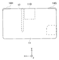
ゲーム装置10は、下側ハウジング11及び上側ハウジング21を備える。上側ハウジング21は、下側ハウジング11に対して開閉可能に連結されている。このため、ゲーム装置10は折り畳みが可能である。このゲーム装置10は、開いた状態(図1,2参照)で使用され、未使用時には閉じた状態(図3A〜図3D参照)で保管される。   The game apparatus 10 includes a lower housing 11 and an upper housing 21. The upper housing 21 is connected to the lower housing 11 so as to be openable and closable. For this reason, the game apparatus 10 can be folded. The game apparatus 10 is used in an open state (see FIGS. 1 and 2), and is stored in a closed state (see FIGS. 3A to 3D) when not in use.

[下側ハウジング11の構成]
図1〜図3Dに示されるように、下側ハウジング11には、下側LCD(Liquid Crystal Display:液晶表示装置)12、タッチパネル13、各操作ボタン14(14A〜14L)、アナログスティック15、LED16A,16B、収容部17、マイクロフォン用孔18、及び無線スイッチ19が設けられている。
[Configuration of Lower Housing 11]
As shown in FIGS. 1 to 3D, the lower housing 11 includes a lower LCD (Liquid Crystal Display) 12, a touch panel 13, operation buttons 14 (14A to 14L), an analog stick 15, and an LED 16A. 16B, the accommodating portion 17, the microphone hole 18, and the wireless switch 19.

下側LCD12は、画像を平面的に表示する横長の表示画面を有しており、下側ハウジング11の内側面11Bの中央に設けられている。下側LCD12の画素数は、本実施形態では256dot×192dot(横×縦)であるが、これ以外の解像度であってもよい。なお、下側LCD12はLCDに限定されるものではなく、例えばEL(Electro Luminescence)を利用した表示装置等の他の表示装置であってもよい。   The lower LCD 12 has a horizontally long display screen for displaying an image in a plane, and is provided at the center of the inner side surface 11 </ b> B of the lower housing 11. The number of pixels of the lower LCD 12 is 256 dots × 192 dots (horizontal × vertical) in the present embodiment, but other resolutions may be used. The lower LCD 12 is not limited to the LCD, and may be another display device such as a display device using EL (Electro Luminescence).

タッチパネル13は、下側LCD12の表示画面を覆うように設けられており、座標入力手段として機能する。タッチパネル13として、本実施形態では抵抗膜方式のタッチパネルが用いられるが、静電容量方式等の他の方式のタッチパネルが用いられてもよい。   The touch panel 13 is provided so as to cover the display screen of the lower LCD 12 and functions as a coordinate input unit. In this embodiment, a resistive film type touch panel is used as the touch panel 13, but another type of touch panel such as a capacitance type may be used.

収容部17(図1、図3Dに示す破線)には、ユーザがタッチパネル13に対する操作に使用するタッチペン28が下側ハウジング11の上面から収納される。なお、タッチパネル13に対する入力は、例えばユーザが指で行うことも可能である。   In the housing portion 17 (broken line shown in FIGS. 1 and 3D), the touch pen 28 used by the user to operate the touch panel 13 is housed from the upper surface of the lower housing 11. Note that the input to the touch panel 13 can be performed by a user with a finger, for example.

図1に示されるように、下側ハウジング11の内側面11Bには、十字ボタン14A、ボタン14B、ボタン14C、ボタン14D、ボタン14E、電源ボタン14F、セレクトボタン14J、HOMEボタン14K、及びスタートボタン14Lが設けられている。また、図3B及び図3Dに示されるように、下側ハウジング11の上面の左端部にLボタン14Gが設けられ、右端部にRボタン14Hが設けられている。また、図3Aに示されるように、下側ハウジング11の左側面には、音量ボタン14Iが設けられている。これらの操作ボタン14A〜14Lには、ゲーム装置10が実行するプログラムに応じた機能が適宜割り当てられる。例えば、十字ボタン14Aは選択操作等に使用され、Lボタン14G及びRボタン14Hは、撮像部による撮影の指示に使用される。   As shown in FIG. 1, on the inner surface 11B of the lower housing 11, a cross button 14A, a button 14B, a button 14C, a button 14D, a button 14E, a power button 14F, a select button 14J, a HOME button 14K, and a start button 14L is provided. As shown in FIGS. 3B and 3D, an L button 14G is provided at the left end of the upper surface of the lower housing 11, and an R button 14H is provided at the right end. Further, as shown in FIG. 3A, a volume button 14 </ b> I is provided on the left side surface of the lower housing 11. A function corresponding to a program executed by the game apparatus 10 is appropriately assigned to these operation buttons 14A to 14L. For example, the cross button 14A is used for a selection operation or the like, and the L button 14G and the R button 14H are used for a shooting instruction by the imaging unit.

アナログスティック15(図1参照)は、方向を指示するデバイスである。このアナログスティック15及び十字ボタン14Aは、下側ハウジング11を把持したユーザが左手の親指で操作可能な位置に設けられている。アナログスティック15は、そのキートップが、下側ハウジング11の内側面11Bに対して平行にスライド可能に構成されており、ゲーム装置10が実行するプログラムに応じて機能する。   The analog stick 15 (see FIG. 1) is a device that indicates a direction. The analog stick 15 and the cross button 14A are provided at a position where the user holding the lower housing 11 can operate with the thumb of the left hand. The analog stick 15 is configured such that its key top is slidable in parallel with the inner side surface 11B of the lower housing 11, and functions in accordance with a program executed by the game apparatus 10.

下側ハウジング11の内側面11Bには、マイクロフォン用孔18が形成されている。下側ハウジング11の内部には、後述するマイク43(図4参照)が設けられており、マイクロフォン用孔18を介して入力された音がマイク43によって検出される。   A microphone hole 18 is formed in the inner surface 11 </ b> B of the lower housing 11. A microphone 43 (see FIG. 4), which will be described later, is provided inside the lower housing 11, and sound input through the microphone hole 18 is detected by the microphone 43.

図3Aに示されるように、下側ハウジング11の左側面には、開閉可能なカバー部11Cが設けられている。このカバー部11Cの内部には、データ保存用外部メモリ46(図1参照)をゲーム装置10に対して着脱可能に装着するためのコネクタ(不図示)が設けられている。データ保存用外部メモリ46は、このコネクタに接続された状態で、例えばゲーム装置10によって撮像されたカメラ画像を記憶(保存)する。   As shown in FIG. 3A, an openable / closable cover portion 11 </ b> C is provided on the left side surface of the lower housing 11. A connector (not shown) for detachably attaching the data storage external memory 46 (see FIG. 1) to the game apparatus 10 is provided inside the cover portion 11C. The external data storage memory 46 stores (saves), for example, a camera image captured by the game apparatus 10 while being connected to the connector.

図3Dに示されるように、下側ハウジング11の上面には、挿入口11Dが形成されている。この挿入口11Dの内部には、画像生成プログラム等を記録した記録媒体としての外部メモリ45(図1参照)をゲーム装置10に対して着脱可能に装着するためのコネクタ(不図示)が設けられている。挿入口11Dから挿入された外部メモリ45がこのコネクタに接続されることで、画像生成プログラムがゲーム装置10に読み出される。   As illustrated in FIG. 3D, an insertion port 11 </ b> D is formed on the upper surface of the lower housing 11. Inside the insertion slot 11D, there is provided a connector (not shown) for detachably attaching an external memory 45 (see FIG. 1) as a recording medium recording an image generation program or the like to the game apparatus 10. ing. When the external memory 45 inserted from the insertion slot 11D is connected to this connector, the image generation program is read out to the game apparatus 10.

図1に示されるように、下側ハウジング11の下面には、第1LED16Aが設けられている。第1LED16Aは、ゲーム装置10の電源のON/OFF状況をユーザに通知する。図3Cに示されるように、下側ハウジング11の右側面には、第2LED16Bが設けられている。ゲーム装置10は、他の機器との間で無線通信を行うことが可能に構成されている。第2LED16Bは、ゲーム装置10の無線通信の確立状況をユーザに通知する。ゲーム装置10は、無線LANに接続する機能を有する。第2LED16Bに近接して設けられた無線スイッチ19が操作されることにより、この無線通信の機能が有効/無効になる。   As shown in FIG. 1, a first LED 16 </ b> A is provided on the lower surface of the lower housing 11. The first LED 16A notifies the user of the power ON / OFF status of the game apparatus 10. As shown in FIG. 3C, the second LED 16 </ b> B is provided on the right side surface of the lower housing 11. The game apparatus 10 is configured to be able to perform wireless communication with other devices. The second LED 16B notifies the user of the wireless communication establishment status of the game apparatus 10. The game apparatus 10 has a function of connecting to a wireless LAN. By operating the wireless switch 19 provided in the vicinity of the second LED 16B, this wireless communication function is enabled / disabled.

[上側ハウジング21の構成]
上側ハウジング21には、上側LCD22(表示手段の一例)、外側撮像部23、内側撮像部24、3D調整スイッチ25、及び3Dインジケータ26が設けられている。
[Configuration of Upper Housing 21]
The upper housing 21 is provided with an upper LCD 22 (an example of a display unit), an outer imaging unit 23, an inner imaging unit 24, a 3D adjustment switch 25, and a 3D indicator 26.

図1に示されるように、ゲーム装置10が折り畳まれた際に内側面11Bと対向する上側ハウジング21の内側面21Bに、上側LCD22が設けられている。上側LCD22は、横長の表示画面を有しており、内側面21Bの中央に設けられている。上側LCD22の画素数は、本実施形態では640dot×200dot(横×縦)であるが、これ以外の解像度であってもよい。なお、上側LCD22はLCDに限定されるものではなく、例えばELを利用した表示装置等の他の表示装置であってもよい。   As shown in FIG. 1, the upper LCD 22 is provided on the inner side surface 21B of the upper housing 21 that faces the inner side surface 11B when the game apparatus 10 is folded. The upper LCD 22 has a horizontally long display screen and is provided at the center of the inner side surface 21B. The number of pixels of the upper LCD 22 is 640 dots × 200 dots (horizontal × vertical) in this embodiment, but other resolutions may be used. The upper LCD 22 is not limited to the LCD, and may be another display device such as a display device using EL.

上側LCD22は、立体視可能な画像(立体画像)を表示する表示装置である。上側LCD22は、実質的に同一の表示領域を用いて左目用画像と右目用画像とを表示する。具体的には、上側LCD22は、左目用画像と右目用画像とを所定単位で(例えば、1列ずつ)横方向に交互に表示する。なお、上側LCD22は、左目用画像と右目用画像とを交互に表示する方式の表示装置であってもよい。また、上側LCD22は、裸眼立体視可能な表示装置である。この場合、上側LCD22は、横方向に交互に表示される左目用画像と右目用画像とを左目及び右目のそれぞれに分解して見えるようにレンチキュラー方式やパララックスバリア方式(視差バリア方式)のものが用いられる。本実施形態では、上側LCD22は、パララックスバリア方式のものとする。上側LCD22は、視差バリアを用いてユーザの左目に左目用画像をユーザの右目に右目用画像をそれぞれ視認させることにより、ユーザにとって立体感のある立体画像(立体視可能な画像)を表示する表示装置として機能する。なお、上側LCD22は、視差バリアを無効にすることができ、これにより、画像を平面的に表示することもできる。   The upper LCD 22 is a display device that displays a stereoscopically visible image (stereoscopic image). The upper LCD 22 displays a left-eye image and a right-eye image using substantially the same display area. Specifically, the upper LCD 22 alternately displays the left-eye image and the right-eye image in the horizontal direction in a predetermined unit (for example, one column at a time). Note that the upper LCD 22 may be a display device that alternately displays a left-eye image and a right-eye image. The upper LCD 22 is a display device capable of autostereoscopic viewing. In this case, the upper LCD 22 is of the lenticular method or the parallax barrier method (parallax barrier method) so that the left-eye image and the right-eye image that are alternately displayed in the horizontal direction appear to be decomposed into the left eye and the right eye, respectively. Is used. In the present embodiment, the upper LCD 22 is a parallax barrier type. The upper LCD 22 uses a parallax barrier to display a left-eye image for the user's left eye and a right-eye image for the user's right eye, thereby displaying a stereoscopic image (stereoscopically visible) that has a stereoscopic effect for the user. Functions as a device. Note that the upper LCD 22 can invalidate the parallax barrier, thereby displaying an image in a planar manner.

3D調整スイッチ25は、図1及び図2に示されるように、上側ハウジング21の内側面11Bと右側面とが交差する部分に設けられている。この3D調整スイッチ25は、例えば上下方向へスライド可能なスライダを有している。このスライダが最下点位置に配置
されている場合、上側LCD22の視差バリアが無効にされ、上側LCD22に画像が平面的に表示される。一方、スライダが最下点よりも上側に配置されている場合、上側LCD22に画像が立体的に表示される。なお、スライダの位置を変化させることで、左目用画像と右目用画像との横方向の位置のズレ量が変化し、立体画像の見え方が調整される。
As shown in FIGS. 1 and 2, the 3D adjustment switch 25 is provided at a portion where the inner side surface 11 </ b> B and the right side surface of the upper housing 21 intersect. The 3D adjustment switch 25 has, for example, a slider that can slide up and down. When this slider is arranged at the lowest point position, the parallax barrier of the upper LCD 22 is invalidated and an image is displayed on the upper LCD 22 in a planar manner. On the other hand, when the slider is arranged above the lowest point, the image is displayed three-dimensionally on the upper LCD 22. Note that by changing the position of the slider, the amount of lateral displacement between the left-eye image and the right-eye image changes, and the appearance of the stereoscopic image is adjusted.

3Dインジケータ26は、図1に示されるように、上側ハウジング21の内側面21Bに設けられている。3Dインジケータ26は上側LCD22が立体表示モードであるか否かを報知するものである。この3Dインジケータ26は、本実施形態ではLEDであり、上側LCD22が立体表示モードであるとき(3D調整スイッチ25が最下点よりも上側に配置されているとき)に点灯する。   As shown in FIG. 1, the 3D indicator 26 is provided on the inner surface 21 </ b> B of the upper housing 21. The 3D indicator 26 notifies whether or not the upper LCD 22 is in the stereoscopic display mode. The 3D indicator 26 is an LED in this embodiment, and lights up when the upper LCD 22 is in the stereoscopic display mode (when the 3D adjustment switch 25 is disposed above the lowest point).

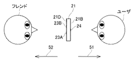
外側撮像部23(第1撮像部の一例)は、図3Bに示されるように、上側ハウジング21の外側面21D(内側面21Bとは反対側の面)に設けられている。この外部撮像部23は、外側左撮像部23A及び外側右撮像部23Bから構成されている。外側左撮像部23A及び外側右撮像部23Bは、それぞれ所定の共通の解像度を有する撮像素子(例えば、CCDイメージセンサやCMOSイメージセンサ等)と、レンズとを有している。外側左撮像部23A及び外側右撮像部23Bは、ユーザが上側LCD22を正面から視認した場合に、図1に示されるように、外側左撮像部23Aが左側に位置すると共に外側右撮像部23Bが右側に位置するように設けられている。なお、外側左撮像部23A及び外側右撮像部23Bの間隔は、人間の両目の間隔程度に設定されている。また、外側左撮像部23A及び外側右撮像部23Bの撮像方向52(図2参照)は、いずれも外側面21Dの外向きの法線方向であり、且つ互いに平行である。   As illustrated in FIG. 3B, the outer imaging unit 23 (an example of the first imaging unit) is provided on the outer surface 21 </ b> D (surface opposite to the inner surface 21 </ b> B) of the upper housing 21. The external imaging unit 23 includes an outer left imaging unit 23A and an outer right imaging unit 23B. The outer left imaging unit 23A and the outer right imaging unit 23B each include an imaging element (for example, a CCD image sensor or a CMOS image sensor) having a predetermined common resolution, and a lens. When the user visually recognizes the upper LCD 22 from the front, the outer left imaging unit 23A and the outer right imaging unit 23B are located on the left side and the outer right imaging unit 23B is located on the left side as shown in FIG. It is provided to be located on the right side. The interval between the outer left imaging unit 23A and the outer right imaging unit 23B is set to be approximately the interval between human eyes. In addition, the imaging directions 52 (see FIG. 2) of the outer left imaging unit 23A and the outer right imaging unit 23B are both outward normal directions of the outer surface 21D and are parallel to each other.

外側左撮像部23Aと外側右撮像部23Bとは、ゲーム装置10が実行するプログラムによって、ステレオカメラとして使用することが可能である。外側撮像部23をステレオカメラとして使用する場合、外側左撮像部23Aは、ユーザの左目で視認されるカメラ画像(左目用画像)を撮像し、外側右撮像部23Bは、ユーザの右目で視認されるカメラ画像(右目用画像)を撮像する。このため、外側撮像部23によって撮像されたカメラ画像を上側LCD22に立体的に表示することが可能である。また、プログラムによっては、外側左撮像部23A及び外側右撮像部23Bのいずれか一方を単独で用いて、外側撮像部23を非ステレオカメラとして使用することも可能である。   The outer left imaging unit 23A and the outer right imaging unit 23B can be used as a stereo camera by a program executed by the game apparatus 10. When the outer imaging unit 23 is used as a stereo camera, the outer left imaging unit 23A captures a camera image (image for the left eye) visually recognized by the user's left eye, and the outer right imaging unit 23B is visually recognized by the user's right eye. The camera image (right eye image) is captured. Therefore, it is possible to display the camera image captured by the outer imaging unit 23 on the upper LCD 22 in a three-dimensional manner. Further, depending on the program, either the outer left imaging unit 23A or the outer right imaging unit 23B can be used alone, and the outer imaging unit 23 can be used as a non-stereo camera.

内側撮像部24(第2撮像部の一例)は、上側ハウジング21の内側面21Bに設けられている。内側撮像部24は、所定の解像度を有する撮像素子(例えば、CCDイメージセンサやCMOSイメージセンサ等)と、レンズとを含む。この内側撮像部24は、外側撮像部23とは反対方向を撮像する撮像部である。すなわち、内側撮像部24の撮像方向51(図2参照)は、上側LCD22の外向きの法線方向と一致している。このため、ユーザが上側LCD22を正視した状態で、内側撮像部24によりユーザ自身の顔を撮像することができる。   The inner imaging unit 24 (an example of a second imaging unit) is provided on the inner side surface 21 </ b> B of the upper housing 21. The inner imaging unit 24 includes an imaging element (for example, a CCD image sensor or a CMOS image sensor) having a predetermined resolution, and a lens. The inner imaging unit 24 is an imaging unit that images in the opposite direction to the outer imaging unit 23. That is, the imaging direction 51 (see FIG. 2) of the inner imaging unit 24 matches the outward normal direction of the upper LCD 22. For this reason, the user's own face can be imaged by the inner imaging unit 24 in a state where the user views the upper LCD 22 from the front.

このように、内側撮像部24の撮像方向51が上側LCD22の法線方向と一致し、且つ外側撮像部23の撮像方向52がこの法線方向の逆方向と一致している(図2参照)。したがって、例えばゲーム装置10のユーザが内側撮像部24で自身の顔を撮影しつつ、外側撮像部23で別の人物(以下「フレンド」という。)の顔を撮影しようとした場合、ユーザとフレンドとが、上側ハウジング21を挟んで向かい合った状態で撮影が行われることとなる。   As described above, the imaging direction 51 of the inner imaging unit 24 matches the normal direction of the upper LCD 22, and the imaging direction 52 of the outer imaging unit 23 matches the opposite direction of the normal direction (see FIG. 2). . Therefore, for example, when the user of the game apparatus 10 attempts to photograph the face of another person (hereinafter referred to as “friend”) with the outer imaging unit 23 while photographing the face with the inner imaging unit 24, the user and the friend However, photographing is performed with the upper housing 21 facing each other.

上側ハウジング21の内側面21Bには、スピーカ孔21Eが形成されている。後述するスピーカ44(図4参照)からの音声は、このスピーカ孔21Eを介して出力される。   A speaker hole 21 </ b> E is formed in the inner surface 21 </ b> B of the upper housing 21. Sound from a speaker 44 (see FIG. 4) described later is output through the speaker hole 21E.

[ゲーム装置10の内部構成]
次に、図4を参照しつつ、ゲーム装置10の内部構成について説明する。ここで、図4は、ゲーム装置10の内部構成の一例を示すブロック図である。
[Internal Configuration of Game Device 10]
Next, the internal configuration of the game apparatus 10 will be described with reference to FIG. Here, FIG. 4 is a block diagram showing an example of the internal configuration of the game apparatus 10.

図4に示されるように、ゲーム装置10は、情報処理部31、メインメモリ32、外部メモリI/F33、データ保存用外部メモリI/F34、データ保存用内部メモリ35、無線通信モジュール36、ローカル通信モジュール37、リアルタイムクロック(RTC)38、加速度センサ39、角速度センサ40、電源回路41、及びI/F回路42等の電子部品を備えている。これらの電子部品は、電子回路基板上に実装されて下側ハウジング11(又は上側ハウジング21)内に収納されている。   As shown in FIG. 4, the game apparatus 10 includes an information processing unit 31, a main memory 32, an external memory I / F 33, an external memory I / F 34 for data storage, an internal memory 35 for data storage, a wireless communication module 36, a local It includes electronic components such as a communication module 37, a real time clock (RTC) 38, an acceleration sensor 39, an angular velocity sensor 40, a power supply circuit 41, and an I / F circuit 42. These electronic components are mounted on an electronic circuit board and accommodated in the lower housing 11 (or the upper housing 21).

情報処理部31は、CPU(Central Processing Unit)311、GPU(Graphics Processing Unit)312、VRAM(Video RAM)313を含む情報処理手段である。本実施形態では、外部メモリ45に画像生成プログラムが記憶されており、CPU311は、外部メモリ45から画像生成プログラムを読み出して実行する。なお、画像生成プログラムは、他の機器との通信によって他の機器から取得されてもよい。   The information processing unit 31 is information processing means including a CPU (Central Processing Unit) 311, a GPU (Graphics Processing Unit) 312, and a VRAM (Video RAM) 313. In the present embodiment, an image generation program is stored in the external memory 45, and the CPU 311 reads the image generation program from the external memory 45 and executes it. Note that the image generation program may be acquired from another device by communication with the other device.

GPU312は、CPU311からの命令に応じてVRAM313に画像を描画し、その画像を上側LCD22及び/又は下側LCD12に出力する。その結果、上側LCD22及び/又は下側LCD12に画像が表示される。   The GPU 312 draws an image on the VRAM 313 in response to a command from the CPU 311 and outputs the image to the upper LCD 22 and / or the lower LCD 12. As a result, an image is displayed on the upper LCD 22 and / or the lower LCD 12.

メインメモリ32は、CPU311のワーク領域やバッファ領域として用いられる揮発性の記憶手段(例えばPSRAM(Pseudo-SRAM))である。メインメモリ32は、情報
処理部31の処理で用いられる各種データを一時的に記憶したり、外部(外部メモリ45や他の機器等)から取得されたプログラムを一時的に記憶したりする。
The main memory 32 is a volatile storage unit (for example, PSRAM (Pseudo-SRAM)) used as a work area or a buffer area of the CPU 311. The main memory 32 temporarily stores various data used in the processing of the information processing unit 31, and temporarily stores programs acquired from the outside (external memory 45, other devices, etc.).

外部メモリI/F33は、外部メモリ45を着脱可能に接続するためのインターフェースである。外部メモリ45は、情報処理部31によって実行されるプログラムを記憶する不揮発性の記憶手段である。外部メモリ45は、例えば読み取り専用の半導体メモリで構成される。外部メモリ45が外部メモリI/F33に接続されると、外部メモリ45に記憶されたプログラムがメインメモリ32に読み込まれて、情報処理部31によって実行される。   The external memory I / F 33 is an interface for detachably connecting the external memory 45. The external memory 45 is a nonvolatile storage unit that stores a program executed by the information processing unit 31. The external memory 45 is constituted by a read-only semiconductor memory, for example. When the external memory 45 is connected to the external memory I / F 33, a program stored in the external memory 45 is read into the main memory 32 and executed by the information processing unit 31.

データ保存用外部メモリI/F34は、データ保存用外部メモリ46を着脱可能に接続するためのインターフェースである。データ保存用外部メモリ46は、不揮発性の読み書き可能なメモリ(例えばNAND型フラッシュメモリ)で構成さる。このデータ保存用外部メモリ46には、例えば外側撮像部23又は内側撮像部24による撮影で得られたカメラ画像が記憶される。データ保存用外部メモリ46がデータ保存用外部メモリI/F34に接続されると、情報処理部31は、データ保存用外部メモリ46に記憶された画像を読み込んで上側LCD22及び/又は下側LCD12に表示することができる。   The data storage external memory I / F 34 is an interface for detachably connecting the data storage external memory 46. The external data storage memory 46 is composed of a non-volatile readable / writable memory (for example, a NAND flash memory). In the data storage external memory 46, for example, a camera image obtained by photographing by the outer imaging unit 23 or the inner imaging unit 24 is stored. When the data storage external memory 46 is connected to the data storage external memory I / F 34, the information processing section 31 reads an image stored in the data storage external memory 46 and loads it to the upper LCD 22 and / or the lower LCD 12. Can be displayed.

データ保存用内部メモリ35は、読み書き可能な不揮発性メモリ(例えばNAND型フラッシュメモリ)で構成される。このデータ保存用内部メモリ35には、例えば無線通信モジュール36を介した無線通信によってダウンロードされたデータやプログラムが格納される。   The data storage internal memory 35 is configured by a readable / writable nonvolatile memory (for example, a NAND flash memory). In the data storage internal memory 35, for example, data and programs downloaded by wireless communication via the wireless communication module 36 are stored.

無線通信モジュール36は、例えばIEEE802.11.b/gの規格に準拠した方式により、無線LANに接続する機能を有する。ローカル通信モジュール37は、所定の通信方式(例えば赤外線通信)により同種のゲーム装置との間で無線通信を行う機能を有する。CPU311は、無線通信モジュール36を用いてインターネットを介して他の機
器との間でデータを送受信したり、ローカル通信モジュール37を用いて同種の他のゲーム装置との間でデータを送受信したりすることができる。
The wireless communication module 36 is, for example, IEEE 802.11. It has a function of connecting to a wireless LAN by a method compliant with the b / g standard. The local communication module 37 has a function of performing wireless communication with the same type of game device by a predetermined communication method (for example, infrared communication). The CPU 311 transmits / receives data to / from other devices via the Internet using the wireless communication module 36, and transmits / receives data to / from other game devices of the same type using the local communication module 37. be able to.

加速度センサ39は、3軸(本実施形態では、xyz軸)方向に沿った直線方向の加速度(直線加速度)の大きさを検出する。加速度センサ39は、図1に示されるように、下側ハウジング11の長手方向をx軸、下側ハウジング11の短手方向をy軸、下側ハウジング11の内側面11Bに対して垂直な方向をz軸として、ゲーム装置10の各軸方向へ生じる直線加速度の大きさをそれぞれ検出する。角速度センサ40は、ゲーム装置10の3軸(本実施形態では、xyz軸)周りに生じるそれぞれの角速度を検出する。CPU311は、加速度センサ39が検出した加速度を示すデータと、角速度センサ40が検出した角速度を示すデータとに基づいて、ゲーム装置10の姿勢や動きを算出することができる。   The acceleration sensor 39 detects the magnitude of linear acceleration (linear acceleration) along the direction of three axes (in this embodiment, the xyz axis). As shown in FIG. 1, the acceleration sensor 39 is configured such that the longitudinal direction of the lower housing 11 is the x axis, the lateral direction of the lower housing 11 is the y axis, and the direction is perpendicular to the inner surface 11B of the lower housing 11. Is the z-axis, and the magnitude of the linear acceleration generated in each axial direction of the game apparatus 10 is detected. The angular velocity sensor 40 detects respective angular velocities that occur around the three axes (in the present embodiment, the xyz axis) of the game apparatus 10. The CPU 311 can calculate the attitude and movement of the game apparatus 10 based on the data indicating the acceleration detected by the acceleration sensor 39 and the data indicating the angular velocity detected by the angular velocity sensor 40.

RTC38は、時間をカウントして情報処理部31に出力する。情報処理部31は、RTC38によって計時された時間に基づき現在時刻(日付)を計算する。電源回路41は、ゲーム装置10が有する電源(例えば下側ハウジング11に収納される充電式電池)からゲーム装置10の各部品に電力を供給する。   The RTC 38 counts the time and outputs it to the information processing unit 31. The information processing unit 31 calculates the current time (date) based on the time counted by the RTC 38. The power supply circuit 41 supplies power to each component of the game apparatus 10 from a power supply (for example, a rechargeable battery housed in the lower housing 11) of the game apparatus 10.

I/F回路42には、マイク43、スピーカ44、及びタッチパネル13が接続されている。マイク43は、ユーザの音声を検知して音声信号をI/F回路42に出力する。スピーカ44は、I/F回路42から不図示のアンプを介して入力された音声信号に応じた音を出力する。I/F回路42は、マイク43及びスピーカ44(アンプ)を制御する音声制御回路を有している。音声制御回路は、音声信号に対するA/D変換及びD/A変換を行ったり、音声信号を所定の形式の音声データに変換したりする。また、I/F回路42は、タッチパネル13を制御するタッチパネル制御回路を有している。タッチパネル制御回路は、タッチパネル13からの信号に基づいて所定の形式のタッチ位置データを生成して情報処理部31に出力する。タッチ位置データは、タッチパネル13の入力面において入力が行われた位置(タッチ位置)の座標を示すデータである。なお、タッチパネル制御回路は、タッチパネル13からの信号の読み込み、及びタッチ位置データの生成を所定時間に1回の割合で行う。CPU311は、タッチ位置データを取得することにより、タッチパネル13に対して入力が行われたタッチ位置を検出することができる。   A microphone 43, a speaker 44, and the touch panel 13 are connected to the I / F circuit 42. The microphone 43 detects the user's voice and outputs a voice signal to the I / F circuit 42. The speaker 44 outputs sound corresponding to the audio signal input from the I / F circuit 42 via an amplifier (not shown). The I / F circuit 42 includes an audio control circuit that controls the microphone 43 and the speaker 44 (amplifier). The audio control circuit performs A / D conversion and D / A conversion on the audio signal, or converts the audio signal into audio data of a predetermined format. The I / F circuit 42 includes a touch panel control circuit that controls the touch panel 13. The touch panel control circuit generates touch position data in a predetermined format based on a signal from the touch panel 13 and outputs it to the information processing unit 31. The touch position data is data indicating the coordinates of the position (touch position) where the input is performed on the input surface of the touch panel 13. The touch panel control circuit reads signals from the touch panel 13 and generates touch position data at a rate of once per predetermined time. The CPU 311 can detect the touch position where the input is performed on the touch panel 13 by acquiring the touch position data.

情報処理部31には、各操作ボタン14A〜14Lの操作状況を示す操作データが出力される。情報処理部31のCPU311は、この操作データに基づいて操作ボタン14A〜14Lの操作の有無を判断し、操作された操作ボタン14に対応する所定の処理を実行する。   Operation data indicating the operation status of each of the operation buttons 14A to 14L is output to the information processing unit 31. The CPU 311 of the information processing unit 31 determines whether or not the operation buttons 14 </ b> A to 14 </ b> L are operated based on the operation data, and executes predetermined processing corresponding to the operated operation button 14.

下側LCD12及び上側LCD22は、情報処理部31(GPU312)の指示に従って画像を表示する。情報処理部31は、例えば、外側撮像部23によって撮像された左目用画像と右目用画像とを用いた立体画像(立体視可能な画像)を上側LCD22に表示させる。   The lower LCD 12 and the upper LCD 22 display images according to instructions from the information processing unit 31 (GPU 312). For example, the information processing unit 31 causes the upper LCD 22 to display a stereoscopic image (a stereoscopically viewable image) using the left-eye image and the right-eye image captured by the outer imaging unit 23.

3D調整スイッチ25は、スライダの位置に応じた電気信号を情報処理部31に出力する。これに対して、情報処理部31(CPU311)は、3D調整スイッチ25からの電気信号に基づいて上側LCD22の表示モードを設定する。また、情報処理部31は、3Dインジケータ26の点灯を制御する。   The 3D adjustment switch 25 outputs an electrical signal corresponding to the position of the slider to the information processing unit 31. On the other hand, the information processing section 31 (CPU 311) sets the display mode of the upper LCD 22 based on the electrical signal from the 3D adjustment switch 25. Further, the information processing section 31 controls lighting of the 3D indicator 26.

なお、上述したハードウェア構成は単なる一例に過ぎず、ゲーム装置10の構成は適宜変更可能である。   Note that the hardware configuration described above is merely an example, and the configuration of the game apparatus 10 can be changed as appropriate.

[顔合成画像を得るための撮影の概要]
次に、図5〜図11を参照しつつ、情報処理部31が画像生成プログラムを実行することによって、外側撮像部23及び内側撮像部24による撮影で得られたカメラ画像から顔合成画像(図9参照)が得られるまでの流れについて説明する。ここで、顔合成画像は、外側撮像部23及び内側撮像部24の一方による撮影で得られたカメラ画像に含まれている顔画像を、外側撮像部23及び内側撮像部24の他方による撮影で得られたカメラ画像に含まれている顔画像に差し替えた画像である。本実施形態では、顔合成画像として、外側撮像部23による撮影で得られたカメラ画像に含まれている顔画像(図11の顔領域92の画像)を、内側撮像部24による撮影で得られたカメラ画像に含まれている顔画像(図11の顔領域91の画像)に差し替えた画像を得る場合を例に説明する。
[Overview of shooting to obtain a face composite image]
Next, referring to FIG. 5 to FIG. 11, when the information processing unit 31 executes the image generation program, a face composite image (FIG. The flow until obtaining 9) will be described. Here, the face composite image is a face image included in a camera image obtained by photographing with one of the outer imaging unit 23 and the inner imaging unit 24 by photographing with the other of the outer imaging unit 23 and the inner imaging unit 24. It is an image replaced with a face image included in the obtained camera image. In the present embodiment, a face image (image of the face area 92 in FIG. 11) included in the camera image obtained by photographing by the outer imaging unit 23 is obtained by photographing by the inner imaging unit 24 as the face composite image. An example of obtaining an image replaced with a face image (image of the face area 91 in FIG. 11) included in the camera image will be described.

図5は、ゲーム装置10を用いた撮影について説明するための説明図である。顔合成画像を得るためには、顔と識別できる少なくとも2つの顔画像が得られるように撮影を行う必要がある。このため、図5に示されるように、ユーザは、内側撮像部24によってユーザ自身の顔が撮影され、且つ外側撮像部23(外側左撮像部23A及び外側右撮像部23B)によってフレンドの顔が撮影されるように、ゲーム装置10を構えて例えばRボタン14Hを押して撮影を指示する。これにより、ユーザの顔画像を含んだカメラ画像が内側撮影部24によって取得され、フレンドの顔画像を含んだカメラ画像が外側撮像部23によって取得される。このように、少なくとも2つの顔画像が取得されるように撮影を行うことで、顔合成画像を生成する処理が可能になる。   FIG. 5 is an explanatory diagram for describing shooting using the game apparatus 10. In order to obtain a face composite image, it is necessary to perform shooting so that at least two face images that can be identified as faces are obtained. For this reason, as shown in FIG. 5, the user's own face is photographed by the inner imaging section 24, and the friend's face is captured by the outer imaging section 23 (the outer left imaging section 23A and the outer right imaging section 23B). To shoot, the game apparatus 10 is held and, for example, the R button 14H is pressed to instruct shooting. Thereby, the camera image including the user's face image is acquired by the inner photographing unit 24, and the camera image including the friend's face image is acquired by the outer imaging unit 23. In this way, by performing shooting so that at least two face images are acquired, it is possible to perform a process of generating a face composite image.

図6は、上側LCD22と下側LCD12の表示例を示す図である。ゲーム装置10が顔合成画像を得るための撮影モードに移行すると、下側LCD12には、ボタン61〜64を含む操作画面が表示される。ボタン61〜64は、それぞれ所定の処理と対応付けられた画像である。ユーザは、下側LCD12に表示されているボタン61〜64を任意に選択することによって、情報処理部31に所定の処理を実行させることができる。タッチパネル13がタッチペン28でタッチされると、タッチ位置に位置するボタン(図6ではボタン61)がハイライト(例えば輪郭強調)される。そして、ボタン上に位置するタッチペン28がタッチパネル13から離されると、ボタンのハイライトが解除されると共にそのボタンに対応する処理が実行される。   FIG. 6 is a diagram showing a display example of the upper LCD 22 and the lower LCD 12. When the game apparatus 10 shifts to a shooting mode for obtaining a face composite image, an operation screen including buttons 61 to 64 is displayed on the lower LCD 12. The buttons 61 to 64 are images associated with predetermined processes, respectively. The user can cause the information processing unit 31 to execute a predetermined process by arbitrarily selecting the buttons 61 to 64 displayed on the lower LCD 12. When the touch panel 13 is touched with the touch pen 28, a button (button 61 in FIG. 6) located at the touch position is highlighted (for example, outline emphasis). When the touch pen 28 located on the button is released from the touch panel 13, highlighting of the button is released and processing corresponding to the button is executed.

ボタン61は、ゲーム装置10を顔合成画像を得るための撮影が可能な状態に移行させるためのボタンである。後述するが、ボタン61が選択されると、上側LCD22に枠71,72と共に、外側撮像部23及び内側撮像部24によってリアルタイムに取得されるカメラ画像が表示される(図7参照)。   The button 61 is a button for shifting the game apparatus 10 to a state in which shooting for obtaining a face composite image is possible. As will be described later, when the button 61 is selected, a camera image acquired in real time by the outer imaging unit 23 and the inner imaging unit 24 is displayed on the upper LCD 22 together with the frames 71 and 72 (see FIG. 7).

ボタン62は、ゲーム装置10で得られた顔合成画像を閲覧するためのボタンである。ボタン62が選択されると、例えばデータ保存用外部メモリ46に記憶されている顔合成画像のサムネイル画像が下側LCD12に一覧表示される。この状態で、ユーザは、所望のサムネイル画像を選択することで、そのサムネイル画像に対応する顔合成画像を上側LCD22に表示させることができる。ボタン63は、外側撮像部23及び内側撮像部24を用いた撮影に関する各種設定の変更を指示するためのボタンである。   The button 62 is a button for browsing the face composite image obtained by the game apparatus 10. When the button 62 is selected, for example, thumbnail images of the face composite image stored in the external data storage memory 46 are displayed in a list on the lower LCD 12. In this state, the user can display a face composite image corresponding to the thumbnail image on the upper LCD 22 by selecting a desired thumbnail image. The button 63 is a button for instructing to change various settings related to shooting using the outer imaging unit 23 and the inner imaging unit 24.

ボタン64は、差し替える側の顔画像と、差し替えられる側の顔画像とを切り替えるためのボタンである。図6に示される例では、ボタン64は、「内カメラ」という文字を含むボタンとして下側LCD12に表示されている。この状態で撮影が行われると、外側撮像部23による撮影で得られたカメラ画像に含まれている顔画像が、内側撮像部24による撮影で得られたカメラ画像に含まれている顔画像に差し替えられた顔合成画像(例えば図9の顔合成画像80)が生成されることになる。つまり、フレンドの顔をユーザの顔に差し替えた顔合成画像が得られる。これに対して、ユーザがタッチペン28を用いた操作
によりボタン64を選択すると、ボタン64は、「外カメラ」という文字を含むボタンとして下側LCD12に表示されることになる。この状態で撮影が行われると、内側撮像部24による撮影で得られたカメラ画像に含まれている顔画像が、外側撮像部23による撮影で得られたカメラ画像に含まれている顔画像に差し替えられた顔合成画像が生成されることになる。つまり、ユーザの顔をフレンドの顔に差し替えた顔合成画像が得られる。
The button 64 is a button for switching between the face image to be replaced and the face image to be replaced. In the example shown in FIG. 6, the button 64 is displayed on the lower LCD 12 as a button including the characters “inner camera”. When shooting is performed in this state, the face image included in the camera image obtained by shooting by the outer imaging unit 23 becomes the face image included in the camera image obtained by shooting by the inner imaging unit 24. The replaced face composite image (for example, the face composite image 80 in FIG. 9) is generated. That is, a face composite image in which the friend's face is replaced with the user's face is obtained. On the other hand, when the user selects the button 64 by an operation using the touch pen 28, the button 64 is displayed on the lower LCD 12 as a button including the characters “outside camera”. When shooting is performed in this state, the face image included in the camera image obtained by shooting by the inner imaging unit 24 is changed to the face image included in the camera image obtained by shooting by the outer imaging unit 23. The replaced face composite image is generated. That is, a face composite image in which the user's face is replaced with the friend's face is obtained.

上側LCD22には、撮影前に外側撮像部23及び内側撮像部24によってリアルタイムに取得されるカメラ画像が表示される。本実施形態では、上側LCD22の表示領域が左領域221(第1表示領域の一例)と右領域222(第2表示領域の一例)の2つの領域に区画されており、外側撮像部23により撮像されたカメラ画像(第1撮像画像)が左領域221に表示され、内側撮像部24により撮像されたカメラ画像(第2撮像画像)が右領域222に表示される。また、上側LCD22の表示画面には、左領域221の所定の位置に枠71が表示され、右領域222の所定の位置に枠72が表示されている。   The upper LCD 22 displays a camera image acquired in real time by the outer imaging unit 23 and the inner imaging unit 24 before shooting. In the present embodiment, the display area of the upper LCD 22 is divided into two areas, a left area 221 (an example of a first display area) and a right area 222 (an example of a second display area). The captured camera image (first captured image) is displayed in the left region 221, and the camera image (second captured image) captured by the inner imaging unit 24 is displayed in the right region 222. On the display screen of the upper LCD 22, a frame 71 is displayed at a predetermined position in the left area 221 and a frame 72 is displayed at a predetermined position in the right area 222.

ところで、顔合成画像を生成するためには、外側撮像部23により撮像されたカメラ画像に対する顔認識処理に成功して顔と識別できる顔画像を取得することができ、且つ、内側撮像部24により撮像されたカメラ画像に対する顔認識処理に成功して顔と識別できる顔画像を取得することができる必要がある。このため、外側撮像部23及び内側撮像部24を用いて撮影を行う際に、内側撮像部24の撮像範囲の中央部にユーザの顔が位置し、且つ外側撮像部23の撮像範囲の中央部にフレンドの顔が位置している状態で撮影が行われることが好ましい。このため、外側撮像部23によって撮像されて左領域221に表示されるフレンドの顔が枠71内に位置し、且つ内側撮像部24によって撮像されて右領域222に表示されるユーザの顔が枠72内に位置した状態で撮影を行うことで、顔合成画像を得ることができる。つまり、ユーザとフレンドとが互いに向かい合った状態で協力して撮影を行うことで、フレンドの顔をユーザの顔に差し替えた極めて興趣性が高い顔合成画像80(図9参照)を得ることができる。   By the way, in order to generate a face composite image, a face image that can be recognized as a face by successfully performing face recognition processing on the camera image captured by the outer imaging unit 23 can be acquired, and the inner imaging unit 24 can acquire the face image. It is necessary to be able to acquire a face image that can be identified as a face by successfully performing face recognition processing on the captured camera image. Therefore, when shooting is performed using the outer imaging unit 23 and the inner imaging unit 24, the user's face is located at the center of the imaging range of the inner imaging unit 24, and the center of the imaging range of the outer imaging unit 23 It is preferable that the photographing is performed in a state where the face of the friend is located. For this reason, the face of the friend imaged by the outer imaging unit 23 and displayed in the left region 221 is located in the frame 71, and the user's face imaged by the inner imaging unit 24 and displayed in the right region 222 is a frame. By capturing the image in a state where the image is located within 72, a face composite image can be obtained. In other words, by taking a picture in cooperation with the user and the friend facing each other, it is possible to obtain a face composition image 80 (see FIG. 9) that is very interesting by replacing the face of the friend with the face of the user. .

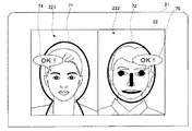
図7は、顔認識処理に成功していないときに上側LCD22に表示される画像の一例を示す上側LCD22の画面図である。図8は、顔認識処理に成功したときに上側LCD22に表示される画像の一例を示す上側LCD22の画面図である。なお、図7以降の画面図においては、外側撮像部23及び内側撮像部24による撮像で得られたカメラ画像における人物の背景の図示が省略されている。   FIG. 7 is a screen diagram of the upper LCD 22 showing an example of an image displayed on the upper LCD 22 when the face recognition process is not successful. FIG. 8 is a screen diagram of the upper LCD 22 showing an example of an image displayed on the upper LCD 22 when the face recognition process is successful. In the screen diagrams of FIG. 7 and subsequent figures, illustration of the background of the person in the camera image obtained by the imaging by the outer imaging unit 23 and the inner imaging unit 24 is omitted.

上述したように、顔合成画像を得るためには、外側撮像部23及び内側撮像部24を用いてそれぞれ顔と識別できる顔画像を含む2つのカメラ画像を得る必要がある。このため、ゲーム装置10は、撮影が指示される前に外側撮像部23及び内側撮像部24によってリアルタイムに取得される2つのカメラ画像に対して顔認識処理を行い、両方のカメラ画像に対して顔認識に成功していなければ、ユーザがLボタン14G又はRボタン14Hを操作しても撮影が行われないように構成されている。言い換えれば、ゲーム装置10は、外側撮像部23によって取得されるカメラ画像と、内側撮像部24によって取得されるカメラ画像との両方のカメラ画像に対する顔認識に成功するまでは、撮影を禁止するように構成されている。ゲーム装置10がこのように構成されていることで、撮影を行ったにも拘わらず顔合成画像が得られないといった問題が生じることを防止することができる。   As described above, in order to obtain a face composite image, it is necessary to obtain two camera images each including a face image that can be identified as a face using the outer imaging unit 23 and the inner imaging unit 24. For this reason, the game apparatus 10 performs face recognition processing on two camera images acquired in real time by the outer imaging unit 23 and the inner imaging unit 24 before shooting is instructed, and both camera images are processed. If the face recognition is not successful, the camera is configured not to shoot even if the user operates the L button 14G or the R button 14H. In other words, the game apparatus 10 prohibits photographing until the face recognition is successful for both the camera image acquired by the outer imaging unit 23 and the camera image acquired by the inner imaging unit 24. It is configured. Since the game apparatus 10 is configured in this way, it is possible to prevent a problem that a face composite image cannot be obtained despite shooting.

ところで、ゲーム装置10が2つのカメラ画像に対する顔認識に成功しなければ撮影を許可しないように構成されているので、顔認識に成功していないこと、或いは顔認識に成功していることをユーザが容易に把握できるようにする必要がある。そこで、本実施形態では、図8に示されるように、外側撮像部23によって取得されたカメラ画像(以下「外カメラ画像」という。)に対する顔認識に成功しているときには左領域221に「OK!」の文字を含む吹き出し74が表示される。また、内側撮像部24によって取得されたカ
メラ画像(以下「内カメラ画像」という。)に対する顔認識に成功しているときには右領域222に「OK!」の文字を含む吹き出し75が表示される。これらの吹き出し74,75は、顔認識に成功しているときだけ上側LCD22に表示され、顔認識に成功していないときには上側LCD22から消去される(図7参照)。このため、ゲーム装置10のユーザが、左領域221に吹き出し74が表示され、且つ右領域222に吹き出し75が表示されるようにゲーム装置10に対するユーザ自身の顔とフレンドの顔の位置を調整してから撮影を指示することで、撮影を成功させることができる。
By the way, since the game apparatus 10 is configured not to allow photographing unless face recognition with respect to two camera images is successful, it is determined that the user has not succeeded in face recognition or has succeeded in face recognition. Need to be easily grasped. Therefore, in the present embodiment, as shown in FIG. 8, when the face recognition for the camera image acquired by the outer imaging unit 23 (hereinafter referred to as “outer camera image”) is successful, “OK” is displayed in the left region 221. A balloon 74 including the characters “!” Is displayed. In addition, when the face recognition for the camera image acquired by the inner imaging unit 24 (hereinafter referred to as “inner camera image”) is successful, a balloon 75 including the characters “OK!” Is displayed in the right region 222. These balloons 74 and 75 are displayed on the upper LCD 22 only when face recognition is successful, and are erased from the upper LCD 22 when face recognition is not successful (see FIG. 7). For this reason, the user of the game apparatus 10 adjusts the position of the user's own face and the friend's face with respect to the game apparatus 10 so that the balloon 74 is displayed in the left area 221 and the balloon 75 is displayed in the right area 222. By instructing shooting afterwards, shooting can be successful.

図9は、撮影に成功した直後に上側LCD22に表示される顔合成画像80の一例を示す上側LCD22の画面図である。図10は、撮影に失敗した直後に上側LCD22に表示されるエラーメッセージ83の一例を示す上側LCD22の画面図である。   FIG. 9 is a screen diagram of the upper LCD 22 showing an example of the face composite image 80 displayed on the upper LCD 22 immediately after successful photographing. FIG. 10 is a screen diagram of the upper LCD 22 showing an example of the error message 83 displayed on the upper LCD 22 immediately after the shooting has failed.

外カメラ画像に対する顔認識、及び内カメラ画像に対する顔認識に成功した状態で撮影が行われると、図9に示されるように、上側LCD22には、リアルタイムに取得される外カメラ画像及び内カメラ画像(例えば図7参照)に代えて、顔合成画像80が表示される。このように、実空間内に位置するユーザとフレンドの顔を忠実に再現したカメラ画像が上側LCD22に表示されていた状態から、フレンドの顔がユーザの顔に差し替えられた実空間には存在しない画像が上側LCD22に表示された状態となることで、ユーザとフレンドとが楽しみながら撮影を行うことができる。   When shooting is performed in a state in which face recognition for the outer camera image and face recognition for the inner camera image are successful, as shown in FIG. 9, the upper LCD 22 displays the outer camera image and the inner camera image acquired in real time. Instead of (for example, see FIG. 7), the face composite image 80 is displayed. Thus, since the camera image faithfully reproducing the face of the user and the friend located in the real space is displayed on the upper LCD 22, it does not exist in the real space where the face of the friend is replaced with the face of the user. Since the image is displayed on the upper LCD 22, the user and the friend can take a picture while enjoying them.

一方、撮影直前に顔認識に成功して上側LCD22に吹き出し74,75が表示された状態でユーザが撮影を指示したとしても、撮影が行われるタイミングで例えばゲーム装置10が動かされて顔の位置が大きくずれてしまった場合、2つのカメラ画像から顔を認識できずに撮影に失敗してしまう場合がある。そこで、本実施形態では、このような場合に、図10に例示されるように上側LCD22にエラーメッセージ83を表示することとしている。これに対して、ゲーム装置10に対するユーザとフレンドの顔の位置をある程度固定したままの状態(上側LCD22に吹き出し74,75が表示されたままの状態)で撮影をやり直すことにより、撮影を上手く成功させることができる。   On the other hand, even if the user instructs shooting with the face recognition succeeded immediately before shooting and the balloons 74 and 75 are displayed on the upper LCD 22, for example, the game apparatus 10 is moved and the position of the face is moved at the timing of shooting. If the image is greatly deviated, the face may not be recognized from the two camera images and shooting may fail. Therefore, in this embodiment, in such a case, an error message 83 is displayed on the upper LCD 22 as illustrated in FIG. On the other hand, the shooting succeeds successfully by re-taking the shooting with the positions of the faces of the user and the friend with respect to the game apparatus 10 being fixed to some extent (while the balloons 74 and 75 are displayed on the upper LCD 22). Can be made.

[顔合成処理の概要]
以下、図11及び図12を参照しつつ、2つのカメラ画像を用いて顔合成画像80を得る処理の概要について説明する。ここで、図11は、上側LCD22に表示されたカメラ画像に含まれている2つの顔領域91,92を例示する上側LCD22の画面図である。図12は、顔合成処理の概要について説明するための説明図である。顔合成画像80を得るための撮影前には、外側撮像部23及び内側撮像部24によってリアルタイムに取得された2つのカメラ画像が上側LCD22に左右に並んで表示されている(例えば図8参照)。この状態でユーザによって撮影が指示されると、撮影によって得られた2つのカメラ画像78,79(図11参照)に対する顔認識処理が行われる。そして、その顔認識処理の結果に基づいて、図11に示されるように、上側LCD22に表示されている2つのカメラ画像78,79に含まれているユーザの顔に相当する顔領域91(第1顔領域の一例)と、フレンドの顔に相当する顔領域92(第2顔領域の一例)との2つの顔領域が検出され、顔領域91の画像が第1顔画像81(図12参照)として取得される。
[Outline of face synthesis process]
Hereinafter, an overview of processing for obtaining the face composite image 80 using two camera images will be described with reference to FIGS. 11 and 12. Here, FIG. 11 is a screen diagram of the upper LCD 22 illustrating the two face areas 91 and 92 included in the camera image displayed on the upper LCD 22. FIG. 12 is an explanatory diagram for explaining an outline of the face synthesis process. Before shooting for obtaining the face composite image 80, two camera images acquired in real time by the outer imaging unit 23 and the inner imaging unit 24 are displayed side by side on the upper LCD 22 (see, for example, FIG. 8). . When shooting is instructed by the user in this state, face recognition processing is performed on the two camera images 78 and 79 (see FIG. 11) obtained by shooting. Then, based on the result of the face recognition process, as shown in FIG. 11, a face area 91 corresponding to the user's face included in the two camera images 78 and 79 displayed on the upper LCD 22 (first display). One face area is detected, and a face area 92 corresponding to a friend's face (an example of a second face area) is detected, and an image of the face area 91 is detected as a first face image 81 (see FIG. 12). ).

ところで、外側撮像部23が外側左撮像部23A及び外側右撮像部23Bから構成されているので、外側撮像部23によって、それぞれフレンドの顔画像を含んでいる2つの外カメラ画像79A,79B(図12参照)が取得されている。このため、フレンドの顔がユーザの顔画像に差し替えられた顔合成画像80を立体表示させるためには、外側左撮像部23Aによって取得された外カメラ画像79Aと、外側右撮像部23Bによって取得された外カメラ画像79Bとのそれぞれの外カメラ画像79に対して、第1顔画像81を合成する必要がある。   By the way, since the outer imaging unit 23 includes an outer left imaging unit 23A and an outer right imaging unit 23B, the outer imaging unit 23 uses the two outer camera images 79A and 79B (FIG. 12) is acquired. Therefore, in order to stereoscopically display the face composite image 80 in which the friend's face is replaced with the user's face image, the outer camera image 79A acquired by the outer left imaging unit 23A and the outer right imaging unit 23B are acquired. It is necessary to synthesize the first face image 81 with each of the outer camera images 79 and the outer camera images 79B.

そこで、第1顔画像81が取得されると、図12に示されるように、第1顔画像81が複製される。そして、外側左撮像部23Aによって取得された外カメラ画像79Aに対して、その外カメラ画像79Aに含まれているフレンドの顔に相当する顔領域92(図11参照)に第1顔画像81を配置した左目用合成画像80Aが生成される。これに伴い、外側右撮像部23Bによって取得されたカメラ画像79Bに対して、そのカメラ画像79Bに含まれているフレンドの顔に相当する顔領域92(図11参照)に複製された第1顔画像81を配置した右目用合成画像80Bが生成される。このようにして生成された左目用合成画像80Aと右目用合成画像80Bとが上側LCD22に表示されることで、フレンドの顔をユーザの顔に差し替えた顔合成画像80が上側LCD22に立体表示される。なお、顔領域91と顔領域92との大きさが異なり、また、ユーザとフレンドの顔の傾きが異なっているので、実際には、第1顔画像81に対して拡大/縮小処理や回転処理が施されるが、これらの処理の詳細については後に詳述する。   Therefore, when the first face image 81 is acquired, the first face image 81 is duplicated as shown in FIG. Then, with respect to the outer camera image 79A acquired by the outer left imaging unit 23A, the first face image 81 is displayed in the face area 92 (see FIG. 11) corresponding to the friend's face included in the outer camera image 79A. The arranged composite image for left eye 80A is generated. Accordingly, the first face copied to the face area 92 (see FIG. 11) corresponding to the friend's face included in the camera image 79B with respect to the camera image 79B acquired by the outer right imaging unit 23B. A right-eye composite image 80B in which the image 81 is arranged is generated. The left-eye composite image 80A and the right-eye composite image 80B generated in this way are displayed on the upper LCD 22, so that the face composite image 80 obtained by replacing the friend's face with the user's face is displayed in three dimensions on the upper LCD 22. The Since the face area 91 and the face area 92 are different in size, and the inclinations of the faces of the user and the friend are different, actually, the first face image 81 is enlarged / reduced or rotated. The details of these processes will be described later.

[メモリマップ]
以下、図13を参照しつつ、メインメモリ32に記憶されるデータについて説明する。ここで、図13は、メインメモリ32のメモリマップである。図13に例示されるように、メインメモリ32は、プログラム記憶領域321及びデータ記憶領域323を有している。プログラム記憶領域321には、CPU311によって実行されるプログラムが記憶される。データ記憶領域323には、顔合成画像を得るための処理に必要な各種データが記憶される。プログラム記憶領域321内のプログラム、及びデータ記憶領域323内のデータの一部は、外部メモリ45に予め記憶されたデータが、顔合成画像を得るための処理に際してメインメモリ32に読み出されたものである。
[Memory map]
Hereinafter, data stored in the main memory 32 will be described with reference to FIG. Here, FIG. 13 is a memory map of the main memory 32. As illustrated in FIG. 13, the main memory 32 includes a program storage area 321 and a data storage area 323. The program storage area 321 stores a program executed by the CPU 311. The data storage area 323 stores various data necessary for processing for obtaining a face composite image. Some of the programs in the program storage area 321 and the data in the data storage area 323 are data stored in advance in the external memory 45 and read into the main memory 32 during the process for obtaining the face composite image It is.

プログラム記憶領域321には、画像生成プログラム322等が記憶されている。画像生成プログラム322は、後述する図14,図15に示されている一連の処理を情報処理部31に実行させるためのプログラムである。   The program storage area 321 stores an image generation program 322 and the like. The image generation program 322 is a program for causing the information processing section 31 to execute a series of processes shown in FIGS.

データ記憶領域323には、カメラ画像データ324、顔認識結果データ325、撮影許可フラグ326、上側LCD表示データ327、下側LCD表示データ328、テクスチャデータ329、ポリゴンデータ330、顔合成画像データ331等が記憶される。   In the data storage area 323, camera image data 324, face recognition result data 325, photographing permission flag 326, upper LCD display data 327, lower LCD display data 328, texture data 329, polygon data 330, face composite image data 331, etc. Is memorized.

カメラ画像データ324は、外側撮像部23及び内側撮像部24が撮像した撮像画像(外カメラ画像及び内カメラ画像)を示すデータである。顔合成画像を得るための撮影において、本実施形態では、外側撮像部23及び内側撮像部24が両方使用されるので、外側撮像部23が撮像した外カメラ画像、及び内側撮像部24が撮像した内カメラ画像によって、カメラ画像データ324が更新される。このカメラ画像データ324の更新周期は、ゲーム装置10が処理を行う時間単位(例えば1/60秒)と同じでもよいし、この時間単位と異なっていてもよい。なお、このカメラ画像データ324には、撮影前に上側LCD22に表示するために取得される外カメラ画像及び内カメラ画像の他に、撮影によって得られた外カメラ画像及び内カメラ画像(図11参照)のデータも含まれている。この外カメラ画像及び内カメラ画像のデータは、撮影が行われる毎に更新される。   The camera image data 324 is data indicating captured images (outer camera image and inner camera image) captured by the outer imaging unit 23 and the inner imaging unit 24. In this embodiment, both the outer imaging unit 23 and the inner imaging unit 24 are used in shooting for obtaining a face composite image. Therefore, the outer camera image captured by the outer imaging unit 23 and the inner imaging unit 24 are captured. The camera image data 324 is updated with the inner camera image. The update cycle of the camera image data 324 may be the same as the time unit (for example, 1/60 second) in which the game apparatus 10 performs processing, or may be different from this time unit. The camera image data 324 includes an outer camera image and an inner camera image obtained by shooting in addition to an outer camera image and an inner camera image acquired for display on the upper LCD 22 before shooting (see FIG. 11). ) Data is also included. The data of the outer camera image and the inner camera image is updated every time shooting is performed.

顔認識結果データ325は、カメラ画像データ324が示すカメラ画像に対して逐次行われる顔認識処理の結果を示すデータである。この顔認識結果データ325は、外カメラ画像及び内カメラ画像に対して行われた顔認識処理によって人物の顔を識別できたか否かを示すデータ、カメラ画像に対して顔として識別できた領域(例えば顔領域91,92)を示すデータ等から構成されている。この顔認識結果データ325に外カメラ画像からフレンドの顔を識別できていることを示すデータが含まれているときに、上述したように、上側LCD22の左領域221に吹き出し74(図8参照)が表示される。また、顔認識
結果データ325に内カメラ画像からユーザの顔を識別できていることを示すデータが含まれている場合、上述したように、上側LCD22の右領域222に吹き出し75(図8参照)が表示される。この顔認識結果データ325は、カメラ画像に対する顔認識処理が行われる毎に適宜更新される。
The face recognition result data 325 is data indicating the result of face recognition processing that is sequentially performed on the camera image indicated by the camera image data 324. This face recognition result data 325 is data indicating whether or not a person's face has been identified by the face recognition processing performed on the outer camera image and the inner camera image, and an area ( For example, it is composed of data indicating the face areas 91 and 92). When the face recognition result data 325 includes data indicating that the friend's face can be identified from the outside camera image, as described above, the balloon 74 (see FIG. 8) is displayed in the left region 221 of the upper LCD 22. Is displayed. When the face recognition result data 325 includes data indicating that the user's face can be identified from the internal camera image, the balloon 75 (see FIG. 8) is displayed in the right area 222 of the upper LCD 22 as described above. Is displayed. The face recognition result data 325 is updated as appropriate every time face recognition processing is performed on a camera image.

撮影許可フラグ326は、顔認識処理に成功することによって、撮影が許可されているか否かを示すデータである。この撮影許可フラグ326は、顔認識結果データ325に顔認識処理によって人物の顔を識別できたことを示すデータが含まれている場合にONに設定される。本実施形態では、外カメラ画像及び内カメラ画像の両方から人物の顔を識別できていることを示すデータが顔認識結果データ325に含まれている場合に、撮影許可フラグ326が「ON」に設定される。撮影許可フラグ326が「ON」に設定されている場合、Lボタン14G又はRボタン14Hの操作に応じて撮影が実行される。一方、顔認識結果データ325に外カメラ画像及び内カメラ画像のいずれか一方でも顔認識処理によって人物の顔を識別できていないことを示すデータが含まれている場合、撮影許可フラグ326が「OFF」に設定される。撮影許可フラグ326が「OFF」に設定されている場合、Lボタン14G又はRボタン14Hが操作されたとしても撮影が行われることはない。   The photographing permission flag 326 is data indicating whether photographing is permitted by successful face recognition processing. The photographing permission flag 326 is set to ON when the face recognition result data 325 includes data indicating that a person's face can be identified by the face recognition process. In the present embodiment, when the face recognition result data 325 includes data indicating that a person's face can be identified from both the outer camera image and the inner camera image, the shooting permission flag 326 is set to “ON”. Is set. When the photographing permission flag 326 is set to “ON”, photographing is performed according to the operation of the L button 14G or the R button 14H. On the other hand, when the face recognition result data 325 includes data indicating that the face of the person cannot be identified by the face recognition process in either the outer camera image or the inner camera image, the photographing permission flag 326 is set to “OFF”. "Is set. When the photographing permission flag 326 is set to “OFF”, photographing is not performed even if the L button 14G or the R button 14H is operated.

上側LCD表示データ327は、上側LCD22に表示される画像に関するデータである。この上側LCD表示データ327には、外側撮像部23によってリアルタイムに取得される外カメラ画像、内側撮像部24によってリアルタイムに取得される内カメラ画像、枠71,72を表す画像、吹き出し74,75を表す画像、エラーメッセージ83の画像等のデータが含まれている。   The upper LCD display data 327 is data relating to an image displayed on the upper LCD 22. The upper LCD display data 327 includes an outer camera image acquired in real time by the outer imaging unit 23, an inner camera image acquired in real time by the inner imaging unit 24, an image representing the frames 71 and 72, and balloons 74 and 75. Data such as an image to be displayed and an image of the error message 83 are included.

下側LCD表示データ328は、下側LCD12に表示される画像に関するデータである。この下側LCD表示データ328には、ボタン61〜64(図6参照)の画像等のデータが含まれている。   The lower LCD display data 328 is data relating to an image displayed on the lower LCD 12. The lower LCD display data 328 includes data such as images of buttons 61 to 64 (see FIG. 6).

テクスチャデータ329は、第1顔画像81(図12参照)をテクスチャマッピングを用いて外カメラ画像上で表現するために使用される顔テクスチャを示すデータである。このテクスチャデータ329は、本実施形態では、内側撮像部24によって撮影時に取得された内カメラ画像78に含まれている顔領域91(図11参照)の画像に基づいて生成される。   The texture data 329 is data indicating a face texture used for expressing the first face image 81 (see FIG. 12) on the outside camera image using texture mapping. In the present embodiment, the texture data 329 is generated based on an image of the face area 91 (see FIG. 11) included in the inner camera image 78 acquired by the inner imaging unit 24 at the time of shooting.

ポリゴンデータ330は、顔認識処理によって識別された顔の特徴点に基づいて生成される複数のポリゴンPG1(図18参照)、複数のポリゴンPG2(図20参照)に関するデータである。ここで、ポリゴンPG1は、内カメラ画像78に対する顔認識処理によって識別された顔の特徴点P1〜P16(図17参照)に基づいて生成された複数のポリゴンである。ポリゴンPG2は、外カメラ画像79に対する顔認識処理によって識別された顔の特徴点P21〜P36(図19参照)に基づいて生成された複数のポリゴンである。なお、本実施形態では、複数のポリゴンPG1が特徴点P1〜P16に基づいて生成され、複数のポリゴンPG2が特徴点P21〜P36に基づいて生成される場合について説明するが、例えば鼻の特徴点P1,P21に代えて後述する口の中心点A4,B4(図17,19参照)を用いて複数のポリゴンPG1,PG2を生成してもよい。ポリゴンデータ330は、テクスチャ座標データ3301、カメラ画像座標データ3302、サイズデータ3303、傾きデータ3304等から構成される。   The polygon data 330 is data relating to a plurality of polygons PG1 (see FIG. 18) and a plurality of polygons PG2 (see FIG. 20) generated based on the facial feature points identified by the face recognition process. Here, the polygon PG <b> 1 is a plurality of polygons generated based on the facial feature points P <b> 1 to P <b> 16 (see FIG. 17) identified by the face recognition processing for the inner camera image 78. The polygon PG <b> 2 is a plurality of polygons generated based on the facial feature points P <b> 21 to P <b> 36 (see FIG. 19) identified by the face recognition process for the outer camera image 79. In the present embodiment, a case will be described in which a plurality of polygons PG1 are generated based on the feature points P1 to P16 and a plurality of polygons PG2 are generated based on the feature points P21 to P36. Instead of P1 and P21, a plurality of polygons PG1 and PG2 may be generated using mouth center points A4 and B4 (see FIGS. 17 and 19) described later. The polygon data 330 includes texture coordinate data 3301, camera image coordinate data 3302, size data 3303, inclination data 3304, and the like.

テクスチャ座標データ3301は、ポリゴンPG1の各頂点が配置されるテクスチャ座標、及びポリゴンPG2の各頂点が配置されるテクスチャ座標を示すデータである。カメラ画像座標データ3302は、ポリゴンPG1の各頂点に対するカメラ画像座標、及びポ
リゴンPG2の各頂点に対するカメラ画像座標を示すデータである。サイズデータ3303は、顔領域91の横サイズX1及び縦サイズY1(図17参照)と、顔領域92の横サイズX2及び縦サイズY2(図19参照)を示すデータを含む。ここで、横サイズX1は、顔領域91が示す顔の左目の中心点A1から右目の中心点A2までの距離を示す。縦サイズY1は、中心点A1と中心点A2とを結ぶ線分αの中点A3から口の中心点A4までの距離を示す。本実施形態では、これらの横サイズX1と縦サイズY1とによって顔領域91の大きさが表される。また、横サイズX2は、顔領域92が示す顔の左目の中心点B1から右目の中心点B2までの距離を示す。縦サイズY2は、中心点B1と中心点B2とを結ぶ線分βの中心点B3から口の中心点B4までの距離を示す。本実施形態では、これらの横サイズX2と縦サイズY2とによって顔領域92の大きさが表される。傾きデータ3304は、水平方向に対する顔領域91が示す顔の傾き(図17に示される線分αの傾き)と、水平方向に対する顔領域92が示す顔の傾き(図19に示される線分βの傾き)を示すデータである。なお、本実施形態においては、これらの点A1〜A4,B1〜B4の座標が顔領域91,92の大きさと傾きを求めるためだけに使用されるが、複数のポリゴンPG1,PG2(図18,20参照)を生成するために使用されてもよい。
The texture coordinate data 3301 is data indicating the texture coordinates where each vertex of the polygon PG1 is arranged and the texture coordinates where each vertex of the polygon PG2 is arranged. The camera image coordinate data 3302 is data indicating the camera image coordinates for each vertex of the polygon PG1 and the camera image coordinates for each vertex of the polygon PG2. The size data 3303 includes data indicating the horizontal size X1 and vertical size Y1 (see FIG. 17) of the face area 91 and the horizontal size X2 and vertical size Y2 (see FIG. 19) of the face area 92. Here, the horizontal size X1 indicates the distance from the center point A1 of the left eye of the face indicated by the face region 91 to the center point A2 of the right eye. The vertical size Y1 indicates the distance from the midpoint A3 of the line segment α connecting the center point A1 and the center point A2 to the center point A4 of the mouth. In the present embodiment, the size of the face area 91 is represented by the horizontal size X1 and the vertical size Y1. The horizontal size X2 indicates the distance from the center point B1 of the left eye of the face indicated by the face region 92 to the center point B2 of the right eye. The vertical size Y2 indicates the distance from the center point B3 of the line segment β connecting the center point B1 and the center point B2 to the center point B4 of the mouth. In the present embodiment, the size of the face area 92 is represented by the horizontal size X2 and the vertical size Y2. The inclination data 3304 includes the face inclination indicated by the face area 91 with respect to the horizontal direction (inclination of the line segment α shown in FIG. 17) and the face inclination indicated by the face area 92 with respect to the horizontal direction (line segment β shown in FIG. 19). Data). In the present embodiment, the coordinates of these points A1 to A4 and B1 to B4 are used only for obtaining the sizes and inclinations of the face regions 91 and 92, but a plurality of polygons PG1 and PG2 (FIG. 18, FIG. 18). 20) may be used.

顔合成画像データ331は、顔合成処理によって得られた顔合成画像(例えば図12に示される左目用顔合成画像80Aと右目用顔合成画像80B)のデータである。顔合成画像を生成する処理が完了すると、顔合成画像データ331が示す顔合成画像は、上側LCD表示データ327の一部として上側LCD22に所定時間表示される。   The face composite image data 331 is data of a face composite image (for example, a left-eye face composite image 80A and a right-eye face composite image 80B shown in FIG. 12) obtained by face synthesis processing. When the process of generating the face composite image is completed, the face composite image indicated by the face composite image data 331 is displayed on the upper LCD 22 as a part of the upper LCD display data 327 for a predetermined time.

なお、図には示されていないが、データ記憶領域323には、ゲーム装置10に対して行われた操作の内容を示す操作データや、仮想ゲーム空間の様子を画面表示するための仮想カメラの制御に関するデータ等が記憶されるが、これらのデータは本発明とは直接関係しないので、ここでの詳細な説明は省略する。   Although not shown in the drawing, in the
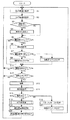
 data storage area 323, operation data indicating the contents of the operation performed on the game apparatus 10 and a virtual camera for displaying the state of the virtual game space on the screen are displayed. Data related to control and the like are stored, but since these data are not directly related to the present invention, detailed description thereof is omitted here.

[メイン処理]
次に、図14を参照しつつ、情報処理部31によって実行されるメイン処理について説明する。ここで、図14は、顔合成画像を生成するためにゲーム装置10で実行される処理の一例を示すフローチャートである。なお、以下に説明する一連の処理は、画像生成プログラム322に基づいてCPU311が発行する命令に従って行われる。
[Main processing]
Next, the main process executed by the information processing unit 31 will be described with reference to FIG. Here, FIG. 14 is a flowchart illustrating an example of processing executed by the game apparatus 10 in order to generate a face composite image. Note that a series of processing described below is performed according to a command issued by the CPU 311 based on the image generation program 322.

ユーザの所定操作によってゲーム装置10が顔合成画像を得るための撮影モードに移行すると、CPU311は、図14に示されるように、カメラ画像を取得する(ステップS1)。具体的には、情報処理部31は、内側撮像部24によって撮像された内カメラ画像と、外側撮像部23によって撮像された外カメラ画像とを取得して、カメラ画像データ324を更新する。そして、第1表示制御手段、第2表示制御手段として機能する情報処理部31は、取得したカメラ画像を上側LCD22に表示させる(ステップS2)。具体的には、CPU311は、ステップS1の処理で取得したカメラ画像の表示をGPU312に対して指示する。これに対して、GPU312は、外カメラ画像及び内カメラ画像、枠71,72等をVRAM313に描画し、描画した画像を上側LCD22に出力する。これにより、例えば図7に示されるように、外カメラ画像が枠71と共に上側LCD22の左領域221に表示されると同時に、内カメラ画像が枠72と共に右領域222に表示される。   When the game apparatus 10 shifts to a shooting mode for obtaining a face composite image by a predetermined operation by the user, the CPU 311 acquires a camera image as shown in FIG. 14 (step S1). Specifically, the information processing unit 31 acquires the inner camera image captured by the inner imaging unit 24 and the outer camera image captured by the outer imaging unit 23 and updates the camera image data 324. Then, the information processing unit 31 functioning as the first display control unit and the second display control unit displays the acquired camera image on the upper LCD 22 (step S2). Specifically, the CPU 311 instructs the GPU 312 to display the camera image acquired in step S1. On the other hand, the GPU 312 draws the outer camera image, the inner camera image, the frames 71 and 72 and the like on the VRAM 313 and outputs the drawn image to the upper LCD 22. As a result, for example, as shown in FIG. 7, the outer camera image is displayed together with the frame 71 in the left region 221 of the upper LCD 22, and the inner camera image is displayed together with the frame 72 in the right region 222.

このように、情報処理部31は、外カメラ画像を外側撮像部23によりリアルタイムに取得して上側LCD22の左領域221に表示させると共に、内カメラ画像を内側撮像部24によりリアルタイムに取得して上側LCD22の右領域222に表示させる。   As described above, the information processing unit 31 acquires the outer camera image in real time by the outer imaging unit 23 and displays it on the left area 221 of the upper LCD 22, and acquires the inner camera image in real time by the inner imaging unit 24. It is displayed on the right area 222 of the LCD 22.

次に、情報処理部31は、データ記憶領域323に記憶されている顔認識結果データ3
25を参照して、既に外カメラ画像又は内カメラ画像に対する顔認識に成功しているか否かを判定する(ステップS3)。顔認識に成功していないと情報処理部31によって判定された場合(ステップS3:NO)、すなわち、外カメラ画像に対する顔認識に失敗し、更に内カメラ画像に対する顔認識にも失敗している場合、処理が後述するステップS5へ進められる。このような場合、図7に例示されるように、上側LCD22には吹き出しが表示されない。
Next, the information processing unit 31 performs face recognition result data 3 stored in the data storage area 323.
Referring to FIG. 25, it is determined whether face recognition has already been successfully performed on the outer camera image or the inner camera image (step S3). When the information processing unit 31 determines that the face recognition is not successful (step S3: NO), that is, when the face recognition for the outer camera image fails and the face recognition for the inner camera image also fails. The process proceeds to step S5 described later. In such a case, no balloon is displayed on the upper LCD 22 as illustrated in FIG.

一方、報知手段として機能する情報処理部31は、外カメラ画像又は内カメラ画像に対する顔認識に成功していると判定した場合(ステップS3:YES)、上側LCD22に吹き出しを表示させる(ステップS4)。このステップS4において、外カメラ画像に対する顔認識に成功している場合、CPU311は、吹き出し74(図8参照)を上側LCD22の左領域221に表示する処理をGPU312に実行させる。また、内カメラ画像に対する顔認識に成功している場合、CPU311は、吹き出し75(図8参照)を上側LCD22の右領域222に表示する処理をGPU312に実行させる。このように、情報処理部31は、外側撮像部23及び内側撮像部24に複数の顔(ここではユーザとフレンドの顔)が含まれていると判定している間、2つの吹き出し74,75を上側LCD22に表示させることにより、撮影が可能であることをユーザに報知する。   On the other hand, when it is determined that the face recognition for the outer camera image or the inner camera image is successful (step S3: YES), the information processing unit 31 functioning as a notification unit displays a balloon on the upper LCD 22 (step S4). . In step S4, when the face recognition for the outside camera image is successful, the CPU 311 causes the GPU 312 to execute a process of displaying the balloon 74 (see FIG. 8) in the left area 221 of the upper LCD 22. If the face recognition for the inner camera image is successful, the CPU 311 causes the GPU 312 to execute a process of displaying the balloon 75 (see FIG. 8) in the right area 222 of the upper LCD 22. As described above, while the information processing unit 31 determines that the outer imaging unit 23 and the inner imaging unit 24 include a plurality of faces (here, the faces of a user and a friend), the two balloons 74 and 75 are used. Is displayed on the upper LCD 22 to notify the user that shooting is possible.

続いて、CPU311は、RTC38から出力される時間情報に基づいて、顔認識処理を実行するタイミングになったか否かを判定する(ステップS5)。顔認識処理を実行するタイミングになっていないとCPU311によって判定された場合(ステップS5:NO)、処理が後述するステップS11へ進められる。一方、CPU311は、顔認識処理を実行するタイミングになったと判定した場合(ステップS5:YES)、所定の顔認識処理を実行する(ステップS6)。この顔認識処理を行った場合、CPU311は、その処理結果に応じて顔認識結果データ325を更新する。なお、顔認識処理は公知の処理であるため、本明細書中ではその詳細な説明を省略する。   Subsequently, the CPU 311 determines whether or not it is time to execute the face recognition process based on the time information output from the RTC 38 (step S5). If the CPU 311 determines that it is not time to execute the face recognition process (step S5: NO), the process proceeds to step S11 to be described later. On the other hand, when the CPU 311 determines that it is time to execute the face recognition process (step S5: YES), the CPU 311 executes a predetermined face recognition process (step S6). When this face recognition processing is performed, the CPU 311 updates the face recognition result data 325 according to the processing result. Since the face recognition process is a known process, detailed description thereof is omitted in this specification.

ステップS6の処理を行った場合、判定手段として機能するCPU311は、顔認識結果データ325を参照して、ステップS1の処理によって取得された外カメラ画像及び内カメラ画像の両方に対して人物の顔を識別できたか否かを判定する(ステップS7)。ここで、外カメラ画像及び内カメラ画像のいずれか一方でも人物の顔を識別できていない場合、顔合成画像を生成することはできない。そこで、撮影禁止手段として機能するCPU311は、外カメラ画像及び内カメラ画像のいずれか一方でも人物の顔を識別できていないと判定した場合(ステップS7:NO)、撮影許可フラグ326を「OFF」に設定する(ステップS8)。一方、CPU311は、外カメラ画像及び内カメラ画像の両方に関して人物の顔を識別できていると判定した場合(ステップS7:YES)、撮影許可フラグ326を「ON」に設定する(ステップS9)。   When the process of step S6 is performed, the CPU 311 functioning as a determination unit refers to the face recognition result data 325, and the person's face for both the outer camera image and the inner camera image acquired by the process of step S1. Is determined (step S7). Here, if either one of the outer camera image and the inner camera image cannot identify the face of a person, a face composite image cannot be generated. Therefore, when the CPU 311 functioning as the photographing prohibiting unit determines that the face of the person cannot be identified in either the outer camera image or the inner camera image (step S7: NO), the photographing permission flag 326 is set to “OFF”. (Step S8). On the other hand, if the CPU 311 determines that the person's face can be identified for both the outer camera image and the inner camera image (step S7: YES), the CPU 311 sets the photographing permission flag 326 to “ON” (step S9).

このように、CPU311は、外側撮像部23及び内側撮像部24によりリアルタイムに取得される外カメラ画像及び内カメラ画像に基づいて、外側撮像部23及び内側撮像部24の撮像範囲に被写体としての複数の顔が含まれているか否かを判定する。そして、CPU311は、外側撮像部23及び内側撮像部24の撮像範囲に複数の顔が含まれていないと判定している間、撮影許可フラグ326を「OFF」に設定することで、Lボタン14G又はRボタン14Hの操作に応じた撮影を禁止する。   As described above, the CPU 311 includes a plurality of objects as subjects within the imaging ranges of the outer imaging unit 23 and the inner imaging unit 24 based on the outer camera image and the inner camera image acquired in real time by the outer imaging unit 23 and the inner imaging unit 24. It is determined whether or not the face is included. The CPU 311 sets the photographing permission flag 326 to “OFF” while determining that a plurality of faces are not included in the imaging ranges of the outer imaging unit 23 and the inner imaging unit 24, thereby causing the L button 14G. Alternatively, shooting in accordance with the operation of the R button 14H is prohibited.

ステップS8の処理を行った場合、ステップS9の処理を行った場合、又はステップS5において顔認識処理を実行するタイミングになっていないと判定した場合(ステップS5:NO)、CPU311は、Lボタン14G又はRボタン14Hが操作されたか否かに基づいて、撮影が指示されたか否かを判定する(ステップS11)。撮影が指示されていないとCPU311によって判定された場合(ステップS11:NO)、処理がステップ
S1へ戻され、撮影が指示されるまでステップS1以降の処理が繰り返される。
When the process of step S8 is performed, when the process of step S9 is performed, or when it is determined that it is not time to execute the face recognition process in step S5 (step S5: NO), the CPU 311 selects the L button 14G. Alternatively, based on whether or not the R button 14H has been operated, it is determined whether or not photographing has been instructed (step S11). If the CPU 311 determines that shooting is not instructed (step S11: NO), the process returns to step S1, and the processes in and after step S1 are repeated until shooting is instructed.

CPU311は、撮影が指示されたと判定した場合(ステップS11:YES)、撮影許可フラグ326が「ON」に設定されているか否かを判定する(ステップS12)。撮影許可フラグ326が「ON」に設定されていないとCPU311によって判定された場合(ステップS12:NO)、処理がステップS1へ戻される。なお、本実施形態では、撮影許可フラグが「OFF」に設定されている場合に処理がステップS1へ戻されるが、撮影許可フラグがOFFに設定されている場合に、人物の顔を識別できていないことをユーザに報知するために、例えばスピーカ44から所定のエラー音を出力してから処理がステップS1へ戻されるようにしてもよい。   If the CPU 311 determines that shooting is instructed (step S11: YES), the CPU 311 determines whether the shooting permission flag 326 is set to “ON” (step S12). If the CPU 311 determines that the photographing permission flag 326 is not set to “ON” (step S12: NO), the process returns to step S1. In this embodiment, when the photographing permission flag is set to “OFF”, the process returns to step S1. However, when the photographing permission flag is set to OFF, the person's face can be identified. In order to notify the user that there is no such error, for example, a predetermined error sound may be output from the speaker 44 and then the process may be returned to step S1.

撮像画像取得手段として機能するCPU311は、撮影許可フラグ326が「ON」に設定されていると判定した場合(ステップS12:YES)、外側撮像部23及び内側撮像部24による撮影を行い(ステップS13)、撮影によって得られた外カメラ画像79及び内カメラ画像78によってカメラ画像データ324を更新する。そして、顔画像取得手段として機能するCPU311は、この撮影によって得られた外カメラ画像79及び内カメラ画像78に対して、ステップS6の処理と同様に、顔認識処理を実行する(ステップS14)。このステップS14の顔認識処理に成功することにより、図11に例示されるように、内カメラ画像78から顔領域91が検出されると共に外カメラ画像79から顔領域92が検出されて、顔領域91の画像が第1顔画像81(図12参照)として取得される。なお、このステップS14では、顔認識処理の結果に応じて、顔認識結果データ325が更新される。   When the CPU 311 functioning as the captured image acquisition unit determines that the shooting permission flag 326 is set to “ON” (step S12: YES), the CPU 311 performs shooting by the outer imaging unit 23 and the inner imaging unit 24 (step S13). ) The camera image data 324 is updated with the outer camera image 79 and the inner camera image 78 obtained by photographing. Then, the CPU 311 functioning as a face image acquisition unit performs face recognition processing on the outer camera image 79 and the inner camera image 78 obtained by this shooting, similarly to the processing in step S6 (step S14). As a result of the successful face recognition processing in step S14, as illustrated in FIG. 11, the face area 91 is detected from the inner camera image 78 and the face area 92 is detected from the outer camera image 79. 91 images are acquired as the first face image 81 (see FIG. 12). In step S14, the face recognition result data 325 is updated according to the result of the face recognition process.

ステップS14の処理に続いて、情報処理部31は、撮影に成功したか否かを判定する(ステップS15)。具体的には、CPU311は、顔認識結果データ325を参照して、ステップS13の処理で得られた外カメラ画像79及び内カメラ画像78の両方に関して、ステップS14の処理によって2人以上の人物の顔(本実施形態ではユーザの顔とフレンドの顔)を識別できたか否かを判定する。   Following the processing in step S14, the information processing section 31 determines whether or not the photographing has been successful (step S15). Specifically, the CPU 311 refers to the face recognition result data 325, and for both the outer camera image 79 and the inner camera image 78 obtained in the process of step S13, the CPU 311 performs processing of two or more persons by the process of step S14. It is determined whether or not a face (in this embodiment, a user's face and a friend's face) has been identified.

情報処理部31は、撮影に成功しなかったと判定した場合(ステップS15:NO)、すなわち外カメラ画像79及び内カメラ画像78のどちらか一方でも人物の顔を識別できなかった場合、図10に例示されるように、GPU312を制御して上側LCD表示データ327に含まれるエラーメッセージ83を上側LCD22に表示させ(ステップS16)、撮影許可フラグ326を「OFF」に設定する(ステップS17)。このステップS17の処理が行われた場合、処理がステップS1へ戻される。   When the information processing unit 31 determines that the photographing has not been successful (step S15: NO), that is, when either one of the outer camera image 79 and the inner camera image 78 cannot identify the face of the person, FIG. As illustrated, the GPU 312 is controlled to display the error message 83 included in the upper LCD display data 327 on the upper LCD 22 (step S16), and the photographing permission flag 326 is set to “OFF” (step S17). When the process of step S17 is performed, the process returns to step S1.

一方、情報処理部31は、撮影に成功したと判定した場合(ステップS15:YES)、すなわち外カメラ画像79及び内カメラ画像78の両方に関して人物の顔を識別できた場合、外カメラ画像79に含まれている人物の顔(ここではフレンドの顔)を内カメラ画像78に含まれている人物の顔(ここではユーザの顔)に差し替えた左目用合成画像80A及び右目用合成画像80B(図12参照)を生成する顔合成処理を実行する(ステップS18)。   On the other hand, if the information processing unit 31 determines that the photographing has been successful (step S15: YES), that is, if the person's face can be identified with respect to both the outer camera image 79 and the inner camera image 78, the outer camera image 79 is displayed. The left-eye composite image 80A and the right-eye composite image 80B (see FIG. 5) in which the face of the person included (here, the face of a friend) is replaced with the face of the person included in the internal camera image 78 (here, the user's face). 12) is generated (step S18).

情報処理部31は、ステップS18の処理によって左目用合成画像80A及び右目用合成画像80Bを生成した後、左目用合成画像80A及び右目用合成画像80Bを顔合成画像データ331としてデータ記憶領域323に記憶させると共に、データ保存用外部メモリ46にも記憶させる(ステップS19)。そして、第1表示制御手段、第2表示制御手段として機能するCPU311は、顔合成画像データ331が示す左目用合成画像80A及び右目用合成画像80Bを用いて、図9に例示されるように、顔合成画像80を上側LCD22に所定時間(例えば5秒間)だけ立体表示させる(ステップS20)。   The information processing section 31 generates the left-eye composite image 80A and the right-eye composite image 80B by the process of step S18, and then stores the left-eye composite image 80A and the right-eye composite image 80B in the data storage area 323 as the face composite image data 331. At the same time, it is also stored in the external data storage memory 46 (step S19). Then, the CPU 311 that functions as the first display control unit and the second display control unit uses the left-eye composite image 80A and the right-eye composite image 80B indicated by the face composite image data 331, as illustrated in FIG. The face composite image 80 is three-dimensionally displayed on the upper LCD 22 for a predetermined time (for example, 5 seconds) (step S20).

顔合成画像80が生成されたことを条件としてこのステップS20の処理が行われることにより、上側LCD22の左領域221に外カメラ画像79が表示されると共に右領域222に内カメラ画像78が表示されていたのが、左領域221及び右領域222の両方を1つの表示領域として用いて顔合成画像80が表示される。このステップS20の処理が行われた場合、処理が上記ステップS1へと戻されて、再び顔合成画像を得るための撮影が可能な状態となる。   By performing the process of step S20 on the condition that the face composite image 80 is generated, the outer camera image 79 is displayed in the left region 221 of the upper LCD 22 and the inner camera image 78 is displayed in the right region 222. What has been described is that the face composite image 80 is displayed using both the left region 221 and the right region 222 as one display region. When the process of step S20 is performed, the process is returned to step S1, and it is possible to perform photographing for obtaining a face composite image again.

[顔合成処理]
図15は、図14のステップS18における顔合成処理の詳細フローチャートである。情報処理部31は、上述したステップS15の処理で撮影に成功したと判定した場合(ステップS15:YES)、複数のポリゴンPG1,PG2の各頂点のカメラ画像座標を設定する(ステップS181)。具体的には、CPU311は、カメラ画像データ324が示す内カメラ画像78と外カメラ画像79及び顔認識結果データ325を用いて、内カメラ画像78における顔の位置及び顔の特徴点P1〜P16(図17参照)の位置を取得すると共に、外カメラ画像79における顔の位置及び顔の特徴点P21〜P36(図19参照)の位置を取得する。そして、CPU311は、内カメラ画像78における特徴点P1〜P16の位置に基づいて複数のポリゴンPG1(図18参照)の各頂点の位置(カメラ画像座標)を設定すると共に、外カメラ画像79における特徴点P21〜P36の位置に基づいて複数のポリゴンPG2(図20参照)の各頂点の位置(カメラ画像座標)を設定する。そして、CPU311は、複数のポリゴンPG1及び複数のポリゴンPG2に対して設定した各頂点の位置を用いて、複数のポリゴンPG1及び複数のポリゴンPG2に対するカメラ画像座標データ3302を更新する。ここで、複数のポリゴンPG1,PG2は、識別された顔における複数の特徴点P1〜P16、P21〜P36に基づいて三角形又は四角形でそれぞれ設定される。また、顔の特徴点P1〜P16、P21〜P36は、公知のソフトウェアを利用して、撮像されたカメラ画像78,79から識別された顔画像(顔領域91,92が示す画像)に対してエッジ検出等の画像処理を施すことによって、顔画像における鼻先1点、眉4点(左右2点ずつ)、顎先端1点、頬10点(左右5点ずつ)の計16点が検出される。なお、複数のポリゴンPG1,PG2の頂点の位置は、検出された顔の特徴点P1〜P16、P21〜P36と一致させる必要はなく、特徴点P1〜P16、P21〜P36の位置に基づいた任意の位置に設定すればよい。
[Face Compositing]
FIG. 15 is a detailed flowchart of the face synthesis process in step S18 of FIG. If the information processing unit 31 determines that the shooting has been successful in the process of step S15 described above (step S15: YES), the information processing unit 31 sets the camera image coordinates of each vertex of the plurality of polygons PG1 and PG2 (step S181). Specifically, the CPU 311 uses the inner camera image 78, the outer camera image 79, and the face recognition result data 325 indicated by the camera image data 324, and the face position and the facial feature points P1 to P16 (in the inner camera image 78). 17), and the positions of the face and the face feature points P21 to P36 (see FIG. 19) in the outer camera image 79 are acquired. The CPU 311 sets the positions (camera image coordinates) of the vertices of the plurality of polygons PG1 (see FIG. 18) based on the positions of the feature points P1 to P16 in the inner camera image 78, and also features in the outer camera image 79. Based on the positions of the points P21 to P36, the position (camera image coordinates) of each vertex of the plurality of polygons PG2 (see FIG. 20) is set. Then, the CPU 311 updates the camera image coordinate data 3302 for the plurality of polygons PG1 and the plurality of polygons PG2, using the positions of the vertices set for the plurality of polygons PG1 and the plurality of polygons PG2. Here, the plurality of polygons PG1 and PG2 are respectively set as a triangle or a rectangle based on the plurality of feature points P1 to P16 and P21 to P36 in the identified face. Also, the facial feature points P1 to P16 and P21 to P36 are for the face images (images indicated by the face areas 91 and 92) identified from the captured camera images 78 and 79 using known software. By performing image processing such as edge detection, a total of 16 points are detected in the face image: one nose tip, four eyebrows (two left and right), one chin tip, and ten cheeks (5 left and right). . Note that the positions of the vertices of the plurality of polygons PG1 and PG2 do not have to coincide with the detected face feature points P1 to P16 and P21 to P36, and are arbitrarily determined based on the positions of the feature points P1 to P16 and P21 to P36 What is necessary is just to set to the position.

このように、ステップS181の処理によって、複数のポリゴンPG1の各頂点のカメラ画像座標が設定される。これにより、上側LCD22に表示された内カメラ画像78及び外カメラ画像79に含まれる顔領域91,92から顔領域91が検出される。   As described above, the camera image coordinates of each vertex of the plurality of polygons PG1 are set by the processing in step S181. Accordingly, the face area 91 is detected from the face areas 91 and 92 included in the inner camera image 78 and the outer camera image 79 displayed on the upper LCD 22.

ところで、図11に例示されるように、内カメラ画像78から検出された顔領域91が示すユーザの顔の傾きと、外カメラ画像79から検出された顔領域92が示すフレンドの顔の傾きとが異なる場合がある。これは、撮影時のユーザとフレンドの姿勢の違い等によるものである。また、顔領域91と顔領域92の大きさが異なる場合がある。これは、ユーザとフレンドの相対的な顔の大きさの違いだけでなく、撮影時における内側撮像部24からユーザの顔までの距離と、外側撮像部23からフレンドの顔までの距離との違いによるものである。このため、顔領域91に対応する第1顔画像81をそのまま顔領域92に配置して顔合成画像を生成した場合、図16に示されるように、興趣性があっても、極めて不自然な顔を示す顔合成画像が得られることとなる。この図16の例では、顔領域92が示す顔に対して第1顔画像81が示す顔が傾いているために、フレンドの髪や上半身に対して顔が不自然に傾いている。また、顔領域92に対して顔領域91が大きいために、フレンドの耳や首、髪等の一部が顔に隠れている。   By the way, as illustrated in FIG. 11, the inclination of the user's face indicated by the face area 91 detected from the inner camera image 78 and the inclination of the friend's face indicated by the face area 92 detected from the outer camera image 79. May be different. This is due to a difference in posture between the user and the friend at the time of shooting. Further, the size of the face area 91 and the face area 92 may be different. This is not only the difference in the relative face size between the user and the friend, but also the difference between the distance from the inner imaging unit 24 to the user's face during shooting and the distance from the outer imaging unit 23 to the friend's face. Is due to. Therefore, when the first face image 81 corresponding to the face area 91 is arranged in the face area 92 as it is and a face composite image is generated, as shown in FIG. 16, even if there is interest, it is extremely unnatural. A face composite image showing the face is obtained. In the example of FIG. 16, the face indicated by the first face image 81 is inclined with respect to the face indicated by the face area 92, and thus the face is unnaturally inclined with respect to the friend's hair and upper body. Further, since the face area 91 is larger than the face area 92, a part of the friend's ears, neck, hair, and the like is hidden in the face.

そこで、本実施形態では、第1顔画像81を外カメラ画像79(79A,79B)に合
成するに際して、第1顔画像81の回転処理と拡大/縮小処理を行うこととしている。
Therefore, in the present embodiment, when the first face image 81 is combined with the outer camera image 79 (79A, 79B), the rotation process and the enlargement / reduction process of the first face image 81 are performed.

図15の説明に戻り、CPU311は、ステップS181の処理によってポリゴンPG1,PG2の各頂点のカメラ画像座標を設定した後、顔領域92(図11参照)の顔に対する顔領域91(図11参照)の顔の傾きを算出する(ステップS182)。具体的には、CPU311は、顔領域91の左目の中心点A1と右目の中心点A2とを両端とする線分αの傾きを算出して、水平方向に対する顔領域91の顔の傾きを求める。また、CPU311は、顔領域92の左目の中心点B1と右目の中心点B2とを両端とする線分βの傾きを算出して、水平方向に対する顔領域92の顔の傾きを求める。そして、CPU311は、これら2つの傾きを用いて傾きデータ3304を更新した後、これら2つの傾きの差を求めることにより、顔領域92の顔に対する顔領域91の顔の傾きを算出する。   Returning to the description of FIG. 15, the CPU 311 sets the camera image coordinates of the vertices of the polygons PG1 and PG2 in the process of step S181, and then the face area 91 (see FIG. 11) for the face of the face area 92 (see FIG. 11). Is calculated (step S182). Specifically, the CPU 311 calculates the inclination of the line segment α with the left eye center point A1 and the right eye center point A2 of the face area 91 as both ends, and obtains the face inclination of the face area 91 with respect to the horizontal direction. . Further, the CPU 311 calculates the inclination of the line segment β having both the left eye center point B1 and the right eye center point B2 of the face area 92 as the two ends, and obtains the face inclination of the face area 92 with respect to the horizontal direction. Then, the CPU 311 calculates the inclination of the face of the face area 91 with respect to the face of the face area 92 by updating the inclination data 3304 using these two inclinations and then obtaining a difference between the two inclinations.

次に、CPU311は、ポリゴンPG1を回転させる(ステップS183)。顔領域91に含まれる顔を回転させる場合、顔領域91を規定する各特徴点P1〜P16の位置を回転移動させる必要がある。このように、顔領域91の各特徴点P1〜P16の位置を変化させた場合、特徴点P1〜P16に基づいて設定したポリゴンPG1の各頂点位置も回転移動させる必要がある。そこで、このステップS183において、CPU311は、ステップS181の処理で設定した複数のポリゴンPG1の各頂点のカメラ画像座標を、ステップS182の処理で算出した傾きに応じて回転移動させた位置に変更し、変更後のカメラ画像座標を用いてカメラ画像座標データ3302を更新する。   Next, the CPU 311 rotates the polygon PG1 (step S183). When the face included in the face area 91 is rotated, the positions of the feature points P1 to P16 that define the face area 91 need to be rotated. As described above, when the positions of the feature points P1 to P16 in the face area 91 are changed, the vertex positions of the polygon PG1 set based on the feature points P1 to P16 also need to be rotated. Therefore, in this step S183, the CPU 311 changes the camera image coordinates of each vertex of the plurality of polygons PG1 set in the process of step S181 to a position rotated according to the inclination calculated in the process of step S182, The camera image coordinate data 3302 is updated using the changed camera image coordinates.

このステップS183の処理が行われることにより、ポリゴンPG1によって表されるユーザの顔の傾きがフレンドの顔の傾き(顔領域92に含まれる顔の傾き)とほぼ一致するように、ポリゴンPG1の各頂点のカメラ画像座標が補正される。   By performing the process in step S183, each of the polygons PG1 is set so that the inclination of the user's face represented by the polygon PG1 substantially matches the inclination of the face of the friend (the inclination of the face included in the face area 92). Vertex camera image coordinates are corrected.

ステップS183の処理に続いて、CPU311は、ポリゴンPG1の大きさを変化させるための倍率(拡大率又は縮小率)を算出する(ステップS184)。具体的には、CPU311は、顔認識結果データ325に含まれている顔領域91(図11参照)を示すデータ(ここでは点A1〜A4の位置を示すデータ)に基づいて、図17に示されるように、顔領域91の横サイズX1と縦サイズY1を算出する。また、CPU311は、顔認識結果データ325に含まれている顔領域92(図11参照)を示すデータ(ここでは点B1〜B4の位置を示すデータ)に基づいて、図19に示されるように、顔領域92の横サイズX2と縦サイズY2を算出する。そして、CPU311は、算出した顔領域91,92のサイズに基づいて、サイズデータ3303を更新する。続いて、CPU311は、サイズデータ3303を参照して、横サイズX1が横サイズX2とほぼ一致し、且つ縦サイズY1が縦サイズY2とほぼ一致するように、ポリゴンPG1の倍率(拡大率又は縮小率)の近似値を算出する。本実施形態では、これまでの説明から明らかなように、顔領域91が顔領域92よりも大きいため、ここでは縮小率が算出される。   Subsequent to the processing in step S183, the CPU 311 calculates a magnification (enlargement ratio or reduction ratio) for changing the size of the polygon PG1 (step S184). Specifically, the CPU 311 shown in FIG. 17 based on data indicating the face area 91 (see FIG. 11) included in the face recognition result data 325 (here, data indicating the positions of the points A1 to A4). As shown, the horizontal size X1 and the vertical size Y1 of the face area 91 are calculated. Further, the CPU 311 is based on data indicating the face area 92 (see FIG. 11) included in the face recognition result data 325 (here, data indicating the positions of the points B1 to B4) as shown in FIG. Then, the horizontal size X2 and the vertical size Y2 of the face area 92 are calculated. Then, the CPU 311 updates the size data 3303 based on the calculated sizes of the face areas 91 and 92. Subsequently, the CPU 311 refers to the size data 3303, and the magnification (enlargement ratio or reduction) of the polygon PG1 so that the horizontal size X1 substantially matches the horizontal size X2 and the vertical size Y1 substantially matches the vertical size Y2. (Approximate rate) is calculated. In this embodiment, since the face area 91 is larger than the face area 92 as is apparent from the above description, the reduction ratio is calculated here.

次に、CPU311は、ステップS184の処理で算出した倍率に応じて、ポリゴンPG1を拡大又は縮小する(ステップS185)。顔領域91の大きさが顔領域92の大きさとほぼ一致するように顔領域91を拡大又は縮小する場合、顔領域91を規定する特徴点P1〜P16間の距離が変化するために、特徴点P1〜P16の位置に基づいて設定されるポリゴンPG1の各頂点の位置を変化させる必要がある。そこで、このステップS185において、CPU311は、カメラ画像座標データ3302を参照して、ステップS183の処理で変更された複数のポリゴンPG1の各頂点のカメラ画像座標を、ステップS184の処理で算出した倍率でポリゴンPG1を拡大又は縮小して移動させた位置に変更し、変更後のカメラ画像座標を用いてカメラ画像座標データ3302を更新する。   Next, the CPU 311 enlarges or reduces the polygon PG1 according to the magnification calculated in the process of step S184 (step S185). When the face area 91 is enlarged or reduced so that the size of the face area 91 substantially matches the size of the face area 92, the distance between the feature points P1 to P16 defining the face area 91 changes. It is necessary to change the position of each vertex of the polygon PG1 set based on the positions of P1 to P16. Therefore, in step S185, the CPU 311 refers to the camera image coordinate data 3302 and calculates the camera image coordinates of each vertex of the plurality of polygons PG1 changed in the process of step S183 at the magnification calculated in the process of step S184. The polygon PG1 is changed to a position moved by enlarging or reducing, and the camera image coordinate data 3302 is updated using the changed camera image coordinates.

このように、複数のポリゴンPG1の傾きや大きさを変化させることによって、第1顔
画像81を外カメラ画像79の顔領域92に配置した場合に、不自然な顔合成画像が得られるのを防止することができる。なお、ここでは、複数のポリゴンPG1の回転処理を行ってから拡大又は縮小処理を行うこととしているが、複数のポリゴンPG1の拡大又は縮小処理を行ってから回転処理を行うようにしてもよい。
As described above, when the first face image 81 is arranged in the face area 92 of the outer camera image 79 by changing the inclination and size of the plurality of polygons PG1, an unnatural face composite image can be obtained. Can be prevented. Here, the enlargement or reduction process is performed after the rotation process of the plurality of polygons PG1, but the rotation process may be performed after the enlargement or reduction process of the plurality of polygons PG1.

続いて、CPU311は、カメラ画像座標データ3302を参照して、ポリゴンPG1の各頂点の位置(テクスチャ座標)を設定し、設定した各頂点の位置に基づいて、ポリゴンPG1のテクスチャ座標データ3301を更新する(ステップS186)。   Subsequently, the CPU 311 refers to the camera image coordinate data 3302 and sets the position (texture coordinate) of each vertex of the polygon PG1, and updates the texture coordinate data 3301 of the polygon PG1 based on the set position of each vertex. (Step S186).

そして、顔合成画像生成手段として機能するCPU311は、ポリゴンPG1に第1顔画像81を描画する(ステップS187)。具体的には、情報処理部31は、顔領域91の画像に基づいて、複数のポリゴンPG1の各ポリゴンにマッピングするためのテクスチャを生成して、テクスチャデータ329を更新する。そして、情報処理部31は、テクスチャ座標データ3301が示す各頂点のテクスチャ座標に基づいて、テクスチャデータ329が示す第1顔画像81のテクスチャを複数のポリゴンPG1の各ポリゴンにマッピングする。そして、情報処理部31は、顔認識結果データ325を参照して、複数のポリゴンPG1の基準点(図17に示される中点A3)が複数のポリゴンPG2の基準点(図19に示される中点B3)と一致するように複数のポリゴンPG1を配置してVRAM313に描画する。その際、第1顔画像81の周縁部と、外カメラ画像79における顔領域92の外側の画像との違和感を低減させるために、画素の透過度を示すアルファ値を、ポリゴンPG1の各頂点に対しては「0」に設定する。   Then, the CPU 311 functioning as a face composite image generation unit draws the first face image 81 on the polygon PG1 (step S187). Specifically, the information processing section 31 generates a texture for mapping to each polygon of the plurality of polygons PG1 based on the image of the face area 91, and updates the texture data 329. Then, the information processing section 31 maps the texture of the first face image 81 indicated by the texture data 329 to each polygon of the plurality of polygons PG1 based on the texture coordinates of each vertex indicated by the texture coordinate data 3301. Then, the information processing section 31 refers to the face recognition result data 325, and the reference points of the plurality of polygons PG1 (the middle point A3 shown in FIG. 17) are the reference points of the plurality of polygons PG2 (the middle points shown in FIG. 19). A plurality of polygons PG1 are arranged so as to coincide with the point B3) and drawn in the VRAM 313. At that time, in order to reduce the discomfort between the peripheral portion of the first face image 81 and the image outside the face area 92 in the outer camera image 79, an alpha value indicating the transparency of the pixel is applied to each vertex of the polygon PG1. On the other hand, it is set to “0”.

このように、Lボタン14G又はRボタン14Hの操作に応じて外側撮像部23及び内側撮像部24により取得された外カメラ画像79及び内カメラ画像78を用いて、第1顔画像81が取得される。そして、それに続いて、第1顔画像81に対して回転処理及び拡大/縮小処理が施され、外カメラ画像79において、顔領域92の画像を処理後の第1顔画像81に差し替えた顔合成画像80が生成される。このようにして生成された顔合成画像80は、ステップS187の処理が完了してステップS20の処理が行われることにより、外カメラ画像79及び内カメラ画像78に代えて上側LCD22に表示される(図9参照)。 As described above, the first face image 81 is acquired using the outer camera image 79 and the inner camera image 78 acquired by the outer imaging unit 23 and the inner imaging unit 24 according to the operation of the L button 14G or the R button 14H. The Subsequently, a rotation process and an enlargement / reduction process are performed on the first face image 81, and the face composition 92 is replaced with the processed first face image 81 in the outer camera image 79. An image 80 is generated. The face composite image 80 generated in this way is displayed on the upper LCD 22 in place of the outer camera image 79 and the inner camera image 78 when the processing of step S187 is completed and the processing of step S20 is performed ( (See FIG. 9).

[本実施形態の作用効果]
以上説明したように、本実施形態によれば、外側撮像部23及び内側撮像部24によって被写体としてのフレンドとユーザの2人の顔がリアルタイムに撮像されて上側LCD22に表示されている状態(例えば図8参照)で、ユーザの顔を表す第1顔画像81が取得される。そして、フレンドの顔に相当する顔領域92(図11参照)を、回転処理及び拡大/縮小処理後の第1顔画像81に差し替えた顔合成画像80が生成される。その結果、被写体としての人物の顔をそのままリアルに再現したカメラ画像ではなく、複数人の顔を合成した興趣性が高い撮像画像を得ることができる。
[Operational effects of this embodiment]
As described above, according to the present embodiment, the outer image capturing unit 23 and the inner image capturing unit 24 capture two faces of the friend and the user as subjects in real time and display them on the upper LCD 22 (for example, In FIG. 8), a first face image 81 representing the user's face is acquired. Then, a face composite image 80 is generated by replacing the face area 92 (see FIG. 11) corresponding to the friend's face with the first face image 81 after the rotation process and the enlargement / reduction process. As a result, it is possible to obtain a highly interesting captured image obtained by synthesizing the faces of a plurality of people, not a camera image that realistically reproduces the face of a person as a subject.

また、本実施形態では、被写体であるユーザとフレンドの顔を忠実に再現したカメラ画像の表示が、興趣性が高い顔合成画像80に切り替わるので、ユーザが上側LCD22を見て顔合成画像80を容易に確認することができる。本実施形態は、撮影が指示されたタイミングで、上側LCD22の表示内容がカメラ画像から顔合成画像80に切り替わるので、撮影直後に顔合成画像80を表示させるための操作を行うことなく顔合成画像80を容易に確認することができ、撮影の楽しさが向上する。   Further, in the present embodiment, the display of the camera image that faithfully reproduces the faces of the user and the friend who are the subjects is switched to the face composition image 80 with high interest, so that the user views the face composition image 80 by looking at the upper LCD 22. It can be easily confirmed. In the present embodiment, since the display content of the upper LCD 22 is switched from the camera image to the face composite image 80 at the timing when shooting is instructed, the face composite image is displayed without performing an operation for displaying the face composite image 80 immediately after shooting. 80 can be easily confirmed, and shooting enjoyment is improved.

また、本実施形態では、外カメラ画像が示すフレンドの顔を内カメラ画像が示すユーザの顔に差し替えた顔合成画像80が生成される。したがって、ユーザは、実空間に存在する(ユーザの目の前にいる)フレンドの顔と、顔合成画像80が示す顔とを見比べて撮影
を楽しむことができる。
In the present embodiment, a face composite image 80 is generated by replacing the friend's face indicated by the outer camera image with the user's face indicated by the inner camera image. Therefore, the user can enjoy photographing by comparing the face of a friend existing in real space (in front of the user's eyes) with the face indicated by the face composite image 80.

また、本実施形態では、Lボタン14G又はRボタン14Hが操作されたときに、第1顔画像81を取得してから顔合成画像80を生成するまでの一連の処理が行われる。すわわち、撮影の直後に顔合成画像80を得ることができる。このため、本実施形態で説明したように、撮影直後に顔合成画像80を上側LCD22に表示させることによってユーザとフレンドとが顔合成画像80を容易に視認することができ、2人で楽しく撮影を行うことができる。   In this embodiment, when the L button 14G or the R button 14H is operated, a series of processes from obtaining the first face image 81 to generating the face composite image 80 is performed. That is, the face composite image 80 can be obtained immediately after shooting. For this reason, as described in the present embodiment, by displaying the face composite image 80 on the upper LCD 22 immediately after shooting, the user and the friend can easily see the face composite image 80, and two people can enjoy shooting. It can be performed.

また、本実施形態では、顔合成画像80を得るために、外カメラ画像と内カメラ画像との両方から人物の顔を識別できていなければシャッターが押せない(撮影が許可されない)ようにゲーム装置10が構成されている。このため、顔認識処理を成功させるために複数人(本実施形態ではユーザとフレンドの2人)が協力して撮影を行う必要があるため、一層楽しく撮影を行うことができる。   Further, in the present embodiment, in order to obtain the face composite image 80, the game apparatus is configured such that the shutter cannot be pressed (shooting is not permitted) unless the human face can be identified from both the outer camera image and the inner camera image. 10 is configured. For this reason, in order to make the face recognition process successful, it is necessary for a plurality of people (two users and a friend in the present embodiment) to perform shooting together, so that shooting can be performed more happily.

また、本実施形態では、外側撮像部23及び内側撮像部24のそれぞれの撮像範囲にフレンドとユーザの顔が含まれている間、撮影が可能であることを報知するために、上側LCD22に吹き出し74,75が表示される。このため、どのタイミングでLボタン14G又はRボタン14Hを操作すれば顔合成画像80を得るための撮影に成功するかをユーザが容易に把握することができ、撮影をスムーズに行うことができる。   In the present embodiment, a balloon is displayed on the upper LCD 22 in order to notify that shooting is possible while the faces of the friend and the user are included in the respective imaging ranges of the outer imaging unit 23 and the inner imaging unit 24. 74 and 75 are displayed. For this reason, the user can easily grasp at what timing the L button 14G or the R button 14H is operated to successfully capture the face composite image 80, and the imaging can be performed smoothly.

また、本実施形態では、上側LCD22の左領域221に外カメラ画像が表示され、右領域222に内カメラ画像が表示されるというように、2つの撮像部23,24によって撮像されたカメラ画像が上側LCD22の異なる表示領域に別々に表示される。したがって、各撮像部23,24の撮像範囲に顔が含まれているか否かをユーザが容易に確認することができ、その結果、撮影をスムーズに行うことができる。   In this embodiment, the camera images captured by the two imaging units 23 and 24 are displayed such that the outer camera image is displayed in the left region 221 of the upper LCD 22 and the inner camera image is displayed in the right region 222. They are displayed separately in different display areas of the upper LCD 22. Therefore, the user can easily confirm whether or not a face is included in the imaging ranges of the imaging units 23 and 24, and as a result, shooting can be performed smoothly.

また、本実施形態では、顔合成画像80が生成されることにより、上側LCD22の表示内容が外カメラ画像79及び内カメラ画像78から顔合成画像80に自動的に切り替わる。このため、ユーザは、この表示内容が切り替わるのを見て楽しむことができる。   Further, in the present embodiment, by generating the face composite image 80, the display content of the upper LCD 22 is automatically switched from the outer camera image 79 and the inner camera image 78 to the face composite image 80. For this reason, the user can enjoy watching the switching of the display contents.

また、本実施形態では、顔合成画像80を得るために、外側撮像部23及び内側撮像部24の両方の撮像部が使用される。このため、ゲーム装置10のユーザが、左領域221及び右領域222の両方に顔が表示されているかを確認しながら、フレンドと向かい合った状態で撮影を行い、撮影直後に上側LCD22に表示された顔合成画像80を2人で確認することで、2人で協力して楽しみながら撮影を行うことができる。   In the present embodiment, in order to obtain the face composite image 80, both the outer imaging unit 23 and the inner imaging unit 24 are used. For this reason, the user of the game apparatus 10 took a picture while facing the friend while checking whether the face is displayed in both the left area 221 and the right area 222, and displayed on the upper LCD 22 immediately after the picture was taken. By confirming the face composite image 80 by two people, it is possible to perform photographing while enjoying the cooperation of the two people.

[他の撮影方法]
上記実施形態では、図5に基づいて説明したように、ユーザの顔が内側撮像部24によって撮像され、且つフレンドの顔が外側撮像部23によって撮像される場合について説明したが、1つの撮像部で撮像される人物の数は1人に限定されるものではない。
[Other shooting methods]
In the above embodiment, as described with reference to FIG. 5, the case where the user's face is imaged by the inner imaging unit 24 and the friend's face is imaged by the outer imaging unit 23 has been described. The number of persons imaged at is not limited to one.

図21は、外側撮像部23及び内側撮像部24の両方の撮像部を用いて、ユーザと2人のフレンドとの3人で撮影を行う場合の撮影方法を模式的に示した図である。図21に例示されるように、ゲーム装置10のユーザが内側撮像部24によって撮像され、第1フレンド及び第2フレンドの2人が外側撮像部23によって撮像されるように、3人で協力して撮影を行うようにしてもよい。この場合、内カメラ画像からユーザの顔を示す第1顔画像を取得して、外カメラ画像に含まれている2人のフレンドの顔領域に2つの第1顔画像を挿入する顔合成処理を行うことが考えられる。この顔合成処理により、第1フレンドと第2フレンドの2人の顔がいずれもユーザの顔に差し替えられた(2人とも別人の顔をした)、興趣性が高い顔合成画像を得ることができる。 FIG. 21 is a diagram schematically illustrating a shooting method in the case where shooting is performed by three users, that is, the user and two friends, using both the outer imaging unit 23 and the inner imaging unit 24. As illustrated in FIG. 21, the three users cooperate such that the user of the game apparatus 10 is imaged by the inner imaging unit 24 and the first friend and the second friend are imaged by the outer imaging unit 23 . You may make it take a picture. In this case, a face compositing process is performed in which the first face image indicating the user's face is acquired from the inner camera image, and the two first face images are inserted into the face areas of the two friends included in the outer camera image. It is possible to do it. By this face synthesis process, both the faces of the first friend and the second friend are replaced with the user's face (both of them are different faces), and a face composition image with high interest can be obtained. it can.

図22は、内側撮像部24のみを用いて、ユーザとフレンドの2人で撮影を行う場合の撮影方法を模式的に示した図である。図22に例示されるように、ゲーム装置10のユーザとフレンドが2人とも内側撮像部24によって撮像されるように、2人で並んで撮影を行うようにしてもよい。この場合、内カメラ画像からフレンドの顔を示す第1顔画像を取得して、第1顔画像を同じ内カメラ画像のユーザの顔領域に挿入する顔合成処理を行うことが考えられる。この顔合成処理により、ユーザとフレンドの2人の顔がいずれもフレンドの顔に差し替えられた、興趣性が高い顔合成画像を得ることができる。このように、外側撮像部23及び内側撮像部24のいずれか一方を用いて複数人の顔を撮影し、それにより得られた1つのカメラ画像から顔合成画像を得るようにしてもよい。   FIG. 22 is a diagram schematically illustrating a photographing method when photographing is performed by two users, a user and a friend, using only the inner imaging unit 24. As illustrated in FIG. 22, two users and friends of the game apparatus 10 may be photographed side by side so that both of them are imaged by the inner imaging unit 24. In this case, it is conceivable to perform a face synthesis process of acquiring a first face image indicating a friend's face from the inner camera image and inserting the first face image into the user's face area of the same inner camera image. By this face composition processing, a face composition image with high interest can be obtained in which the faces of both the user and the friend are replaced with the faces of the friend. As described above, a face composite image may be obtained from one camera image obtained by photographing the faces of a plurality of people using one of the outer imaging unit 23 and the inner imaging unit 24.

[変形例]
なお、本発明は上記実施形態に限定されるものではなく、以下の形態であってもよい。すなわち、上記実施形態では、フレンドの顔領域92(第2顔領域の一例)の全体を、ユーザの顔領域91(第1顔領域の一例)の全体に対応する第1顔画像81に差し替えて顔合成画像80を得る場合について説明した。これに代えて、第1顔領域の一部の画像を第1顔画像として取得し、第2顔領域の一部をこの第1顔画像に差し替えるようにしてもよい。つまり、ある人物の顔の一部(例えば目)を別の人物の顔の一部(同じく目)に差し替えた顔合成画像を生成するようにしてもよい。
[Modification]
In addition, this invention is not limited to the said embodiment, The following forms may be sufficient. That is, in the above embodiment, the entire face area 92 (an example of the second face area) of the friend is replaced with the first face image 81 corresponding to the entire face area 91 (an example of the first face area) of the user. The case where the face composite image 80 is obtained has been described. Alternatively, a part of the first face area may be acquired as the first face image, and a part of the second face area may be replaced with the first face image. That is, a face composite image in which a part of a person's face (for example, eyes) is replaced with a part of another person's face (also eyes) may be generated.

また、上記実施形態では、外カメラ画像が示す人物の顔を内カメラ画像が示す人物の顔に差し替えた顔合成画像を生成する場合について説明したが、これとは逆に、内カメラ画像が示す人物の顔を外カメラ画像が示す人物の顔に差し替えた顔合成画像を生成するようにしてもよい。これにより、外側撮像部23によって撮影される人物が、目の前で撮影を行っているゲーム装置10のユーザの顔と、例えば撮影後に上側LCD22に表示される顔合成画像とを見比べて、ユーザとの撮影を楽しむことができる。   In the above-described embodiment, the case has been described in which the face composite image in which the face of the person indicated by the outer camera image is replaced with the face of the person indicated by the inner camera image is generated. You may make it produce | generate the face composite image which replaced the person's face with the person's face which an outside camera image shows. As a result, the person photographed by the outer imaging unit 23 compares the face of the user of the game apparatus 10 photographing in front of his eyes with the face composite image displayed on the upper LCD 22 after photographing, for example. You can enjoy shooting with.

また、上記実施形態では、外側撮像部23をステレオカメラとして使用して、立体的に表示される顔合成画像80(左目用合成画像80A及び右目用合成画像80B)を得る場合について説明したが、外側撮像部23を非ステレオカメラとして使用して、平面的に表示される顔合成画像を得るようにしてもよい。この形態の一例としては、外側撮像部23の外側左撮像部23Aだけを使用して、外側左撮像部23Aによって取得された1つの外カメラ画像に対して、内側撮像部24によって取得された内カメラ画像に含まれている第1顔画像を合成して顔合成画像を得る形態が挙げられる。   In the above embodiment, the case has been described in which the outer imaging unit 23 is used as a stereo camera to obtain a three-dimensionally displayed face composite image 80 (left-eye composite image 80A and right-eye composite image 80B). The outer imaging unit 23 may be used as a non-stereo camera to obtain a face composite image displayed in a plane. As an example of this form, only the outer left imaging unit 23A of the outer imaging unit 23 is used, and the inner imaging unit 24 acquired by the inner imaging unit 24 for one outer camera image acquired by the outer left imaging unit 23A. There is a mode in which a face composite image is obtained by synthesizing a first face image included in a camera image.

また、上記実施形態では、リアルタイムに取得される外カメラ画像及び内カメラ画像が上側LCD22の異なる表示領域に表示される場合について説明したが、上側LCD22と下側LCD12の両方を用いてカメラ画像を表示するようにしてもよい。すなわち、外カメラ画像を上側LCD22に表示し、内カメラ画像を下側LCD12に表示するようにしてもよい。 In the above embodiment, the case where the outer camera image and the inner camera image acquired in real time are displayed in different display areas of the upper LCD 22 has been described. However, the camera image using both the upper LCD 22 and the lower LCD 12 is used. May be displayed. That is, the outer camera image may be displayed on the upper LCD 22 and the inner camera image may be displayed on the lower LCD 12.

また、上記実施形態では、顔合成画像80が上側LCD22に表示される場合について説明したが、顔合成画像80を下側LCD12に表示するようにしてもよい。例えば撮影後も上側LCD22に内カメラ画像78及び外カメラ画像79を表示し続けるようにすれば、撮影時のカメラ画像78,79と顔合成画像80とを見比べることができる。また、顔合成画像80を、ゲーム装置10と通信可能に接続された液晶テレビの画面に表示するようにしてもよい。   In the above embodiment, the case where the face composite image 80 is displayed on the upper LCD 22 has been described. However, the face composite image 80 may be displayed on the lower LCD 12. For example, if the inner camera image 78 and the outer camera image 79 are continuously displayed on the upper LCD 22 after photographing, the camera images 78 and 79 at the time of photographing and the face composite image 80 can be compared. Further, the face composite image 80 may be displayed on a screen of a liquid crystal television connected so as to be communicable with the game apparatus 10.

また、上記実施形態では、Lボタン14G又はRボタン14Hの操作に応じて、第1顔
画像(上記実施形態では第1顔画像81)を取得して顔合成画像を生成する場合について説明した。これに代えて、第1顔画像を取得して顔合成画像を生成する処理を、自動的に行うようにしてもよい。例えば、リアルタイムに取得される外カメラ画像及び内カメラ画像に対して顔認識処理を行い、両方のカメラ画像から顔を識別できたタイミングで、第1顔画像を取得して顔合成画像を生成することが考えられる。
Further, in the above embodiment, a case has been described in which a first face image (first face image 81 in the above embodiment) is acquired and a face composite image is generated in response to an operation of the L button 14G or the R button 14H. Instead of this, the process of acquiring the first face image and generating the face composite image may be automatically performed. For example, face recognition processing is performed on the outer camera image and the inner camera image acquired in real time, and the first face image is acquired and the face composite image is generated at the timing when the face can be identified from both camera images. It is possible.

また、上記実施形態では、撮像部の撮像範囲に複数の顔が含まれていない場合に撮影が禁止される場合について説明したが、撮像範囲に複数の顔が含まれているか否かに関わらず、撮影が行えるようにしてもよい。ただし、この場合、ゲーム装置10に対する顔の位置によって顔合成画像が得られないケースが生じるので、上記実施形態で説明したように、顔認識処理に成功したことを条件として撮影を行えるようにすることが好ましい。 In the above-described embodiment, the case where shooting is prohibited when the imaging range of the imaging unit does not include a plurality of faces has been described. However, regardless of whether or not the imaging range includes a plurality of faces. It may be possible to perform shooting. However, in this case, a face composite image may not be obtained depending on the position of the face with respect to the game apparatus 10, and as described in the above embodiment, shooting can be performed on the condition that the face recognition process has been successful. It is preferable.

また、上記実施形態では、携帯型のゲーム装置10に本発明が適用された場合を例に説明したが、本発明は、ゲーム装置に限らず、任意の携帯型電子機器、例えば、PDA(Personal Digital Assistance)や携帯電話等に適用されてもよい。   In the above embodiment, the case where the present invention is applied to the portable game apparatus 10 has been described as an example. However, the present invention is not limited to the game apparatus, and any portable electronic device such as a PDA (Personal Digital Assistance) and mobile phones may be applied.

また、上記実施形態では、顔合成画像を得るまでの全ての処理をゲーム装置10で行う場合を例に説明したが、一部の処理を他の装置で行っても構わない。例えば、ゲーム装置10が他の装置(例えば、サーバや他のゲーム装置)と通信可能に接続されている場合、上述したメイン処理における処理ステップは、ゲーム装置10及び他の装置が1つの撮像システムとして協働することによって実行されてもよい。また、上記実施形態においては、ゲーム装置10の情報処理部31が所定のプログラムを実行することによって、上述したフローチャートによる処理が行われたが、ゲーム装置10が備える専用回路によって上記処理の一部又は全部が行われてもよい。   Moreover, although the case where all the processes until obtaining the face composite image are performed by the game apparatus 10 has been described as an example in the above embodiment, a part of the processes may be performed by another apparatus. For example, when the game apparatus 10 is communicably connected to another apparatus (for example, a server or another game apparatus), the processing steps in the main process described above are an imaging system in which the game apparatus 10 and the other apparatus are one. May be implemented by cooperating as In the above embodiment, the processing according to the above-described flowchart is performed by the information processing unit 31 of the game device 10 executing a predetermined program. However, a part of the above processing is performed by a dedicated circuit included in the game device 10. Or all may be done.

また、上述したゲーム装置10の形状、撮像部の数、撮像部の設置位置、撮像部の撮像方向等は単なる一例に過ぎず、他の形状、数、及び設置位置であっても、本発明を実現できることは言うまでもない。また、上述したメイン処理で用いられる処理順序、設定値、判定に用いられる値等は、単なる一例に過ぎず他の順序や値であっても、本発明を実現できることは言うまでもない。   In addition, the shape of the game apparatus 10 described above, the number of imaging units, the installation position of the imaging unit, the imaging direction of the imaging unit, and the like are merely examples, and the present invention may be applied to other shapes, numbers, and installation positions. It goes without saying that can be realized. Further, it is needless to say that the present invention can be realized even if the processing order used in the main processing described above, the set value, the value used for determination, and the like are merely examples and have other orders and values.

また、画像生成プログラムは、外部メモリ45やデータ保存用外部メモリ46等の外部記憶媒体を通じてゲーム装置10に供給されるだけでなく、有線又は無線の通信回線を通じてゲーム装置10に供給されてもよい。また、上記画像生成プログラムは、ゲーム装置10内部の不揮発性記憶装置に予め記録されていてもよい。なお、上記プログラムを記憶する情報記憶媒体としては、不揮発性メモリの他に、CD−ROM、DVD、或いはそれらに類する光学式ディスク状記憶媒体、フレキシブルディスク、ハードディスク、光磁気ディスク、磁気テープ等であってもよい。また、上記プログラムを記憶する情報記憶媒体としては、上記プログラムを一時的に記憶するRAM等の揮発性メモリでもよい。   Further, the image generation program may be supplied not only to the game apparatus 10 through an external storage medium such as the external memory 45 or the data storage external memory 46 but also to the game apparatus 10 through a wired or wireless communication line. . The image generation program may be recorded in advance in a nonvolatile storage device inside the game apparatus 10. In addition to the nonvolatile memory, the information storage medium for storing the program includes CD-ROM, DVD, or similar optical disk storage medium, flexible disk, hard disk, magneto-optical disk, magnetic tape, etc. There may be. The information storage medium that stores the program may be a volatile memory such as a RAM that temporarily stores the program.

以上、本発明を詳細に説明してきたが、上述の説明はあらゆる点において本発明の例示に過ぎず、その範囲を限定しようとするものではない。本発明の範囲を逸脱することなく種々の改良や変形を行うことができることは言うまでもない。   Although the present invention has been described in detail above, the above description is merely illustrative of the present invention in all respects and is not intended to limit the scope thereof. It goes without saying that various improvements and modifications can be made without departing from the scope of the present invention.

本発明は、人物等の顔を撮像して得られた撮像画像に対して顔認識機能を用いて画像処理を行う撮像装置のコンピュータに実行させる画像生成プログラム、撮像装置、撮像システム、及び画像生成方法等に適用可能である。   The present invention relates to an image generation program, an imaging apparatus, an imaging system, and image generation that are executed by a computer of an imaging apparatus that performs image processing using a face recognition function on a captured image obtained by imaging a face such as a person. Applicable to methods and the like.

10 ゲーム装置
22 上側LCD
23 外側撮像部(第1撮像部の一例)
24 内側撮像部(第2撮像部の一例)
31 情報処理部
32 メインメモリ
51 撮像方向
52 撮像方向
78 内カメラ画像(撮像画像の一例)
79 外カメラ画像(撮像画像の一例)
80 顔合成画像
81 第1顔画像
91 顔領域(第1顔領域の一例)
92 顔領域(第2顔領域の一例)
221 左領域(第1表示領域の一例)
222 右領域(第2表示領域の一例)
311 CPU
312 GPU
313 VRAM
10 Game device 22 Upper LCD
23 Outside imaging unit (an example of a first imaging unit)
24 Inner imaging unit (an example of a second imaging unit)
31 Information processing section 32 Main memory 51 Imaging direction 52 Imaging direction 78 Internal camera image (an example of a captured image)
79 Outside camera image (example of captured image)
80 face composite image 81 first face image 91 face area (example of first face area)
92 face area (example of second face area)
221 Left area (an example of a first display area)
222 Right area (example of second display area)
311 CPU
312 GPU
313 VRAM

Claims (11)

撮像装置のコンピュータに実行させる画像生成プログラムであって、
前記コンピュータを、
所定の操作に応じて、少なくとも1つの撮像部によりリアルタイムに撮像画像を取得する撮像画像取得手段と、
前記撮像画像取得手段によって取得された撮像画像に含まれる複数の顔領域から第1顔領域を検出し、当該第1顔領域の少なくとも一部の画像を第1顔画像として取得する顔画像取得手段と、
前記複数の顔領域のうちの前記第1顔領域とは異なる第2顔領域の少なくとも一部を前記第1顔画像に差し替えた顔合成画像を生成する顔合成画像生成手段と
前記撮像画像に基づいて、前記少なくとも1つの撮像部の撮像範囲に被写体としての複数の顔が含まれているか否かを判定する判定手段と、
前記撮像範囲に複数の顔が含まれていないと前記判定手段によって判定されている間、前記所定の操作に応じた撮影を禁止する撮影禁止手段と、
前記撮像範囲に複数の顔が含まれていると前記判定手段によって判定されている間、前記所定の操作に応じた撮影が可能であることを報知する報知手段として機能させる、画像生成プログラム。
An image generation program to be executed by a computer of an imaging apparatus,
The computer,
In accordance with a predetermined operation, captured image acquisition means for acquiring a captured image in real time by at least one imaging unit;
Face image acquisition means for detecting a first face area from a plurality of face areas included in the captured image acquired by the captured image acquisition means and acquiring at least a part of the first face area as a first face image. When,
A face composite image generating means for generating a face composite image by replacing at least a part of a second face region different from the first face region of the plurality of face regions with the first face image ;
Determining means for determining whether or not a plurality of faces as subjects are included in an imaging range of the at least one imaging unit based on the captured image;
Shooting prohibiting means for prohibiting shooting in accordance with the predetermined operation while the determination means determines that the imaging range does not include a plurality of faces;
Wherein while it is determined by said determining means includes a plurality of faces in the imaging range, to function as a notifying means for informing that it is possible to shoot in accordance with the predetermined operation, the image generating program .
前記コンピュータを、前記撮像画像取得手段によってリアルタイムに取得される撮像画像を表示手段に表示させ、前記顔合成画像生成手段によって顔合成画像が生成されたことを条件として、当該顔合成画像を前記撮像画像に代えて前記表示手段に表示させる第1表示制御手段として更に機能させる、請求項1に記載の画像生成プログラム。   The computer displays the captured image acquired in real time by the captured image acquisition unit on the display unit, and captures the face composite image on the condition that the face composite image is generated by the face composite image generation unit. The image generation program according to claim 1, further functioning as first display control means for displaying on the display means instead of an image. 前記コンピュータを、第1撮像部により撮像された第1撮像画像を表示手段の第1表示領域に表示させ、第2撮像部により撮像された第2撮像画像を前記第1表示領域とは異なる前記表示手段の第2表示領域に表示させる第2表示制御手段として更に機能させる、請求項1に記載の画像生成プログラム。   The computer causes the first captured image captured by the first imaging unit to be displayed in the first display area of the display unit, and the second captured image captured by the second imaging unit is different from the first display area. The image generation program according to claim 1, which further functions as second display control means for displaying in the second display area of the display means. 前記第2表示制御手段は、前記顔合成画像生成手段によって顔合成画像が生成されたことを条件として、当該顔合成画像を前記第1撮像画像及び前記第2撮像画像に代えて前記表示手段に表示させる、請求項に記載の画像生成プログラム。 The second display control means replaces the face composite image with the first captured image and the second captured image on the display means on the condition that the face composite image is generated by the face composite image generation means. The image generation program according to claim 3 , which is displayed. 前記第1撮像部及び前記第2撮像部のいずれか一方の撮像方向が前記表示手段の法線方向と一致し、且つ前記第1撮像部及び前記第2撮像部の他方の撮像方向が当該法線方向の逆方向と一致する、請求項に記載の画像生成プログラム。 The imaging direction of one of the first imaging unit and the second imaging unit matches the normal direction of the display means, and the other imaging direction of the first imaging unit and the second imaging unit is the method. The image generation program according to claim 3 , wherein the image generation program matches the reverse direction of the line direction. 前記撮像画像取得手段は、第1撮像部および第2撮像部により前記撮像画像を取得し、The captured image acquisition means acquires the captured image by the first imaging unit and the second imaging unit,
前記コンピュータを、The computer,
前記第1撮像部の第1撮像範囲に被写体としての顔が含まれているという第1条件、及び前記第2撮像部の第2撮像範囲に被写体としての顔が含まれているという第2条件がいずれか一方でも満たされていない場合に、前記第1撮像部および前記第2撮像部による撮影を禁止する撮影禁止手段として更に機能させる、請求項1に記載の画像生成プログラム。A first condition that a face as a subject is included in the first imaging range of the first imaging unit, and a second condition that a face as a subject is included in the second imaging range of the second imaging unit. 2. The image generation program according to claim 1, further causing an image capturing prohibiting unit to prohibit image capturing by the first image capturing unit and the second image capturing unit in a case where any of the above is not satisfied.
前記撮像画像取得手段は、第1撮像部および第2撮像部により前記撮像画像を取得し、The captured image acquisition means acquires the captured image by the first imaging unit and the second imaging unit,
前記コンピュータを、The computer,
前記第1撮像部の第1撮像範囲に被写体としての顔が含まれている場合に、その旨を示唆する第1示唆画像を表示する第1示唆画像表示手段と、When a face as a subject is included in the first imaging range of the first imaging unit, a first suggestion image display means for displaying a first suggestion image that suggests that,
前記第2撮像部の第2撮像範囲に被写体としての顔が含まれている場合に、その旨を示唆する第2示唆画像を表示する第2示唆画像表示手段として更に機能させる、請求項1に記載の画像生成プログラム。When the 2nd imaging range of the said 2nd imaging part contains the face as a to-be-photographed object, it further functions as a 2nd suggestion image display means which displays the 2nd suggestion image which suggests that. The image generation program described.
前記顔画像取得手段は、特定の操作に応じて、前記複数の顔領域から検出する前記第1顔領域を変更可能である、請求項1に記載の画像生成プログラム。The image generation program according to claim 1, wherein the face image acquisition unit can change the first face area detected from the plurality of face areas in accordance with a specific operation. 所定の操作に応じて、少なくとも1つの撮像部によりリアルタイムに撮像画像を取得する撮像画像取得手段と、
前記撮像画像取得手段によって取得された撮像画像に含まれる複数の顔領域から第1顔領域を検出し、当該第1顔領域の少なくとも一部の画像を第1顔画像として取得する顔画像取得手段と、
前記複数の顔領域のうちの前記第1顔領域とは異なる第2顔領域の少なくとも一部を前記第1顔画像に差し替えた顔合成画像を生成する顔合成画像生成手段と
前記撮像画像に基づいて、前記少なくとも1つの撮像部の撮像範囲に被写体としての複数の顔が含まれているか否かを判定する判定手段と、
前記撮像範囲に複数の顔が含まれていないと前記判定手段によって判定されている間、前記所定の操作に応じた撮影を禁止する撮影禁止手段と、
前記撮像範囲に複数の顔が含まれていると前記判定手段によって判定されている間、前記所定の操作に応じた撮影が可能であることを報知する報知手段とを備える、撮像装置。
In accordance with a predetermined operation, captured image acquisition means for acquiring a captured image in real time by at least one imaging unit;
Face image acquisition means for detecting a first face area from a plurality of face areas included in the captured image acquired by the captured image acquisition means and acquiring at least a part of the first face area as a first face image. When,
A face composite image generating means for generating a face composite image by replacing at least a part of a second face region different from the first face region of the plurality of face regions with the first face image ;
Determining means for determining whether or not a plurality of faces as subjects are included in an imaging range of the at least one imaging unit based on the captured image;
Shooting prohibiting means for prohibiting shooting in accordance with the predetermined operation while the determination means determines that the imaging range does not include a plurality of faces;
An imaging apparatus comprising: an informing unit that informs that photographing according to the predetermined operation is possible while the determination unit determines that a plurality of faces are included in the imaging range .
所定の操作に応じて、少なくとも1つの撮像部によりリアルタイムに撮像画像を取得する撮像画像取得手段と、
前記撮像画像取得手段によって取得された撮像画像に含まれる複数の顔領域から第1顔領域を検出し、当該第1顔領域の少なくとも一部の画像を第1顔画像として取得する顔画像取得手段と、
前記複数の顔領域のうちの前記第1顔領域とは異なる第2顔領域の少なくとも一部を前記第1顔画像に差し替えた顔合成画像を生成する顔合成画像生成手段と
前記撮像画像に基づいて、前記少なくとも1つの撮像部の撮像範囲に被写体としての複数の顔が含まれているか否かを判定する判定手段と、
前記撮像範囲に複数の顔が含まれていないと前記判定手段によって判定されている間、前記所定の操作に応じた撮影を禁止する撮影禁止手段と、
前記撮像範囲に複数の顔が含まれていると前記判定手段によって判定されている間、前記所定の操作に応じた撮影が可能であることを報知する報知手段とを含む、撮像システム。
In accordance with a predetermined operation, captured image acquisition means for acquiring a captured image in real time by at least one imaging unit;
Face image acquisition means for detecting a first face area from a plurality of face areas included in the captured image acquired by the captured image acquisition means and acquiring at least a part of the first face area as a first face image. When,
A face composite image generating means for generating a face composite image by replacing at least a part of a second face region different from the first face region of the plurality of face regions with the first face image ;
Determining means for determining whether or not a plurality of faces as subjects are included in an imaging range of the at least one imaging unit based on the captured image;
Shooting prohibiting means for prohibiting shooting in accordance with the predetermined operation while the determination means determines that the imaging range does not include a plurality of faces;
An imaging system including a notifying unit that notifies that shooting according to the predetermined operation is possible while the determination unit determines that a plurality of faces are included in the imaging range .
撮像装置に実行される画像生成方法であって、
所定の操作に応じて、少なくとも1つの撮像部によりリアルタイムに撮像画像を取得するステップと、
取得された前記撮像画像に含まれる複数の顔領域から第1顔領域を検出し、当該第1顔領域の少なくとも一部の画像を第1顔画像として取得するステップと、
前記複数の顔領域のうちの前記第1顔領域とは異なる第2顔領域の少なくとも一部を前記第1顔画像に差し替えた顔合成画像を生成するステップと
前記撮像画像に基づいて、前記少なくとも1つの撮像部の撮像範囲に被写体としての複数の顔が含まれているか否かを判定するステップと、
前記撮像範囲に複数の顔が含まれていないと判定されている間、前記所定の操作に応じた撮影を禁止するステップと、
前記撮像範囲に複数の顔が含まれていると判定されている間、前記所定の操作に応じた撮影が可能であることを報知するステップとを含む、画像生成方法。
An image generation method executed by an imaging apparatus,
Acquiring a captured image in real time by at least one imaging unit according to a predetermined operation ;
Detecting a first face area from a plurality of face areas included in the acquired captured image, and acquiring at least a partial image of the first face area as a first face image;
Generating a face composite image by replacing at least a part of a second face area different from the first face area among the plurality of face areas with the first face image ;
Determining whether a plurality of faces as subjects are included in an imaging range of the at least one imaging unit based on the captured image; and
Prohibiting shooting according to the predetermined operation while it is determined that the imaging range does not include a plurality of faces;
An image generation method comprising: notifying that shooting according to the predetermined operation is possible while it is determined that the imaging range includes a plurality of faces .
JP2010217531A 2010-09-28 2010-09-28 Image generation program, imaging apparatus, imaging system, and image generation method Active JP5564384B2 (en)

Priority Applications (2)

Application Number Priority Date Filing Date Title
JP2010217531A JP5564384B2 (en) 2010-09-28 2010-09-28 Image generation program, imaging apparatus, imaging system, and image generation method
US13/247,348 US8648924B2 (en) 2010-09-28 2011-09-28 Computer-readable storage medium having stored thereon image generation program, capturing apparatus, capturing system, and image generation method for generating a combination image on a display of the capturing apparatus

Applications Claiming Priority (1)

Application Number Priority Date Filing Date Title
JP2010217531A JP5564384B2 (en) 2010-09-28 2010-09-28 Image generation program, imaging apparatus, imaging system, and image generation method

Publications (2)

Publication Number Publication Date
JP2012074878A JP2012074878A (en) 2012-04-12
JP5564384B2 true JP5564384B2 (en) 2014-07-30

Family

ID=45870289

Family Applications (1)

Application Number Title Priority Date Filing Date
JP2010217531A Active JP5564384B2 (en) 2010-09-28 2010-09-28 Image generation program, imaging apparatus, imaging system, and image generation method

Country Status (2)

Country Link
US (1) US8648924B2 (en)
JP (1) JP5564384B2 (en)

Families Citing this family (14)

* Cited by examiner, † Cited by third party
Publication number Priority date Publication date Assignee Title
KR101817658B1 (en) * 2011-12-23 2018-02-22 삼성전자주식회사 Digital photographing apparatus splay apparatus and control method thereof
JP5450739B2 (en) * 2012-08-30 2014-03-26 シャープ株式会社 Image processing apparatus and image display apparatus
US20140135121A1 (en) * 2012-11-12 2014-05-15 Samsung Electronics Co., Ltd. Method and apparatus for providing three-dimensional characters with enhanced reality
KR102076773B1 (en) * 2013-01-04 2020-02-12 삼성전자주식회사 Method for obtaining video data and an electronic device thereof
CN104536578B (en) * 2015-01-13 2018-02-16 京东方科技集团股份有限公司 Control method and device, the bore hole 3D display device of bore hole 3D display device
US9852543B2 (en) * 2015-03-27 2017-12-26 Snap Inc. Automated three dimensional model generation
US11284003B2 (en) * 2015-07-29 2022-03-22 Samsung Electronics Co., Ltd. User terminal apparatus and control method thereof
USD836654S1 (en) * 2016-10-28 2018-12-25 General Electric Company Display screen or portion thereof with graphical user interface
CN107330408B (en) * 2017-06-30 2021-04-20 北京乐蜜科技有限责任公司 Video processing method and device, electronic equipment and storage medium
CN109523461A (en) * 2018-11-09 2019-03-26 北京达佳互联信息技术有限公司 Method, apparatus, terminal and the storage medium of displaying target image
US11704851B2 (en) * 2020-05-27 2023-07-18 Snap Inc. Personalized videos using selfies and stock videos
USD956068S1 (en) * 2020-09-14 2022-06-28 Apple Inc. Display screen or portion thereof with graphical user interface
JP2023543799A (en) 2020-09-25 2023-10-18 アップル インコーポレイテッド How to navigate the user interface
JP7218031B1 (en) 2022-08-01 2023-02-06 三信トレーディング株式会社 Automatic biological measuring device, method and program

Family Cites Families (10)

* Cited by examiner, † Cited by third party
Publication number Priority date Publication date Assignee Title
JP4377472B2 (en) * 1999-03-08 2009-12-02 株式会社東芝 Face image processing device
JP2003296713A (en) * 2002-04-04 2003-10-17 Mitsubishi Electric Corp Device and method for synthesizing facial images, communication terminal provided with program for performing the method and facial image synthesizing device and communicating method by the communication terminal
JP4383140B2 (en) * 2003-09-25 2009-12-16 任天堂株式会社 Image processing apparatus and image processing program
JP3948485B2 (en) * 2006-03-08 2007-07-25 松下電器産業株式会社 Digital camera and mobile phone device with digital camera
JP5239126B2 (en) 2006-04-11 2013-07-17 株式会社ニコン Electronic camera
JP4577275B2 (en) * 2006-06-07 2010-11-10 カシオ計算機株式会社 Imaging apparatus, image recording method, and program
KR101431535B1 (en) * 2007-08-30 2014-08-19 삼성전자주식회사 Apparatus and method for picturing image using function of face drecognition
JP2010056883A (en) * 2008-08-28 2010-03-11 Nikon Corp Optical device and photographing device
JP5727692B2 (en) * 2008-12-04 2015-06-03 任天堂株式会社 Program and information processing apparatus
US8839118B2 (en) * 2010-06-30 2014-09-16 Verizon Patent And Licensing Inc. Users as actors in content

Also Published As

Publication number Publication date
JP2012074878A (en) 2012-04-12
US20120075496A1 (en) 2012-03-29
US8648924B2 (en) 2014-02-11

Similar Documents

Publication Publication Date Title
JP5564384B2 (en) Image generation program, imaging apparatus, imaging system, and image generation method
JP4869430B1 (en) Image processing program, image processing apparatus, image processing system, and image processing method
JP5750253B2 (en) Image generation program, imaging apparatus, imaging system, and image generation method
JP5671349B2 (en) Image processing program, image processing apparatus, image processing system, and image processing method
JP5739671B2 (en) Information processing program, information processing apparatus, information processing system, and information processing method
US9495800B2 (en) Storage medium having stored thereon image processing program, image processing apparatus, image processing system, and image processing method
JP5739674B2 (en) Information processing program, information processing apparatus, information processing system, and information processing method
JP5646263B2 (en) Image processing program, image processing apparatus, image processing system, and image processing method
JP5627973B2 (en) Program, apparatus, system and method for game processing
JP5702653B2 (en) Information processing program, information processing apparatus, information processing system, and information processing method
WO2013001902A1 (en) Image processing device, method for controlling image processing device, program, and information storage medium
JP6723512B2 (en) Image processing apparatus, image processing method and program
JP5514637B2 (en) Information processing program, information processing apparatus, information processing system, and information processing method
JP2005216061A (en) Image processor, image processing method, recording medium, computer program and semiconductor device
JP2007042073A (en) Video presentation system, video presentation method, program for causing computer to execute video presentation method and storage medium
JP2012174237A (en) Display control program, display control device, display control system and display control method
US20120072857A1 (en) Computer-readable storage medium, display control apparatus, display control method and display control system
US9737814B2 (en) Computer readable medium storing image processing program of synthesizing images
US20130057574A1 (en) Storage medium recorded with program, information processing apparatus, information processing system, and information processing method
JP2012243147A (en) Information processing program, information processing device, information processing system, and information processing method
JP2012000193A (en) Information processing program, information processing apparatus, information processing system, and information processing method
JP5602702B2 (en) Image processing program, image processing apparatus, image processing system, and image processing method
JP5687881B2 (en) Display control program, display control device, display control system, and display control method
JP5723149B2 (en) Image processing system, image processing program, image processing method, and image processing apparatus
JP2016001476A (en) Display control program, display control device, display control system and display control method

Legal Events

Date Code Title Description
A621 Written request for application examination

Free format text: JAPANESE INTERMEDIATE CODE: A621

Effective date: 20130807

A977 Report on retrieval

Free format text: JAPANESE INTERMEDIATE CODE: A971007

Effective date: 20140228

A131 Notification of reasons for refusal

Free format text: JAPANESE INTERMEDIATE CODE: A131

Effective date: 20140307

A521 Request for written amendment filed

Free format text: JAPANESE INTERMEDIATE CODE: A523

Effective date: 20140502

TRDD Decision of grant or rejection written
A01 Written decision to grant a patent or to grant a registration (utility model)

Free format text: JAPANESE INTERMEDIATE CODE: A01

Effective date: 20140522

A61 First payment of annual fees (during grant procedure)

Free format text: JAPANESE INTERMEDIATE CODE: A61

Effective date: 20140616

R150 Certificate of patent or registration of utility model

Ref document number: 5564384

Country of ref document: JP

Free format text: JAPANESE INTERMEDIATE CODE: R150

R250 Receipt of annual fees

Free format text: JAPANESE INTERMEDIATE CODE: R250

R250 Receipt of annual fees

Free format text: JAPANESE INTERMEDIATE CODE: R250

R250 Receipt of annual fees

Free format text: JAPANESE INTERMEDIATE CODE: R250

R250 Receipt of annual fees

Free format text: JAPANESE INTERMEDIATE CODE: R250

R250 Receipt of annual fees

Free format text: JAPANESE INTERMEDIATE CODE: R250

R250 Receipt of annual fees

Free format text: JAPANESE INTERMEDIATE CODE: R250

R250 Receipt of annual fees

Free format text: JAPANESE INTERMEDIATE CODE: R250