JP5560230B2 - Packet relay method, packet relay apparatus, and packet relay system. - Google Patents
Packet relay method, packet relay apparatus, and packet relay system. Download PDFInfo
- Publication number
- JP5560230B2 JP5560230B2 JP2011098948A JP2011098948A JP5560230B2 JP 5560230 B2 JP5560230 B2 JP 5560230B2 JP 2011098948 A JP2011098948 A JP 2011098948A JP 2011098948 A JP2011098948 A JP 2011098948A JP 5560230 B2 JP5560230 B2 JP 5560230B2
- Authority
- JP
- Japan
- Prior art keywords
- packet
- relay
- node
- information
- child node
- Prior art date
- Legal status (The legal status is an assumption and is not a legal conclusion. Google has not performed a legal analysis and makes no representation as to the accuracy of the status listed.)
- Active
Links
Images


Classifications
-
- Y—GENERAL TAGGING OF NEW TECHNOLOGICAL DEVELOPMENTS; GENERAL TAGGING OF CROSS-SECTIONAL TECHNOLOGIES SPANNING OVER SEVERAL SECTIONS OF THE IPC; TECHNICAL SUBJECTS COVERED BY FORMER USPC CROSS-REFERENCE ART COLLECTIONS [XRACs] AND DIGESTS
- Y02—TECHNOLOGIES OR APPLICATIONS FOR MITIGATION OR ADAPTATION AGAINST CLIMATE CHANGE
- Y02D—CLIMATE CHANGE MITIGATION TECHNOLOGIES IN INFORMATION AND COMMUNICATION TECHNOLOGIES [ICT], I.E. INFORMATION AND COMMUNICATION TECHNOLOGIES AIMING AT THE REDUCTION OF THEIR OWN ENERGY USE
- Y02D30/00—Reducing energy consumption in communication networks
- Y02D30/70—Reducing energy consumption in communication networks in wireless communication networks
Description
本発明は、複数の無線通信機器から伝送されたパケットを、周囲の無線通信機器に伝送
するパケット中継方法、パケット中継装置およびパケット中継方法に関する。
The present invention relates to a packet relay method, a packet relay device, and a packet relay method for transmitting packets transmitted from a plurality of wireless communication devices to surrounding wireless communication devices.
低炭素化社会の実現に向けて、スマートグリッドのようなエネルギー管理や、エネルギー見える化による省エネ行動動機づけなどの実施が急務となっている。これらを実現するため、家庭、ビル、プラント、店舗などのエネルギー情報をきめ細かく監視したいという要求がある。エネルギー監視のための情報収集として、既設の建物に容易に設置可能な無線通信によるデータ収集が注目を集めている。 For the realization of a low-carbon society, there is an urgent need to implement energy management like a smart grid and motivation for energy-saving behavior by visualizing energy. In order to realize these, there is a demand for detailed monitoring of energy information of homes, buildings, plants, stores, and the like. As information collection for energy monitoring, data collection by wireless communication that can be easily installed in existing buildings is attracting attention.
しかし一般的に、無線通信によるデータ収集は、有線通信と比較して通信の信頼性が低く、また通信範囲は無線の届く範囲に限られる。さらに、通信の電波環境は、障害物などにより時々刻々変化するため、通信が安定しにくい。例に挙げた家庭、ビル等の静的な物体でも、通信経路が物などの障害物によって遮断されてしまう恐れがある。 However, in general, data collection by wireless communication is less reliable than wired communication, and the communication range is limited to a wireless reachable range. Furthermore, the radio wave environment of communication changes from moment to moment due to obstacles and the like, making it difficult to stabilize communication. Even in static objects such as homes and buildings mentioned as examples, there is a possibility that the communication path is blocked by an obstacle such as an object.
そこで、複数の無線通信機器を利用しマルチホップ通信を行うことで無線通信の範囲を拡大させ、さらに複数経路からデータを伝送する、つまり、冗長にデータを伝送することでデータ収集の信頼性を向上させる手法が提案されている。 Therefore, the range of wireless communication is expanded by performing multi-hop communication using a plurality of wireless communication devices, and further, data is transmitted from multiple paths, that is, the reliability of data collection is increased by transmitting data redundantly. Techniques for improvement have been proposed.
特許文献1に記載の技術では、予め決められた中継ルートで通信することが決められ、中継端末はパケットを受け取った際にACKを返すことによってデータの送信を確認し、データ収集の信頼性を高めている。
In the technique described in
無線によるデータ収集を行う際、機器に取り付けるセンサなどの無線通信機器は電池駆
動のものが多く、できるだけ省電力に設計したいという要求がある。
When wireless data collection is performed, there are many battery-driven wireless communication devices such as sensors attached to the device, and there is a demand for designing power saving as much as possible.
特許文献1の技術では、各中継端末はパケット送信後にACKを受け取る必要があるため、その間電源を落とさずに待つことが必要である。そのため、ACKを待つ時間の消費電力が無駄に消費される問題がある。ACK待ち時間は送信時間に比べて短時間であるが、転送速度の遅い通信やACKを正常に受信できなかった場合のタイムアウト時間などを考慮すると、微小量とはいえ積み重なると大きな消費電力量となる。例えば、送信パケット長が100パケットで、ACKパケット長が5パケットの場合、消費電力は1/20程度削減できる。
In the technique of
本発明は、パケット送信後に動作モードをスリープモードにする無線通信機器がパケッ
トを送信し、
そのパケットを受信した他の無線通信機器は、パケットが子ノードから送信されたものであるか否かを判定し、
判定結果に基づいて受信したパケットから新たなパケットを生成する。
In the present invention, a wireless communication device that sets an operation mode to a sleep mode after transmitting a packet transmits a packet,
The other wireless communication device that has received the packet determines whether or not the packet is transmitted from a child node.
A new packet is generated from the received packet based on the determination result.
本発明によれば、データの信頼性を保ちながら、省電力にすることができる。 According to the present invention, it is possible to save power while maintaining the reliability of data.
以降、本発明を実施するための最良の形態(「本実施形態」という)を、図等を参照しながら詳細に説明する。図1〜図11は実施形態を示す図であり、これらの図において、同一の符号を付した部分は同一物を表し、基本的な構成および動作は同様であるものとする。 Hereinafter, the best mode for carrying out the present invention (referred to as “the present embodiment”) will be described in detail with reference to the drawings. FIGS. 1-11 is a figure which shows embodiment, In these figures, the part which attached | subjected the same code | symbol represents the same thing, and the fundamental structure and operation | movement shall be the same.
図1は、データ収集向け無線ネットワークシステムの全体構成の構成を示す図である。実線矢印で示している部分が子ノードから親ノードへと通信する経路である。また、点線矢印で示している部分は親子関係ではないが、無線電波として通信が可能な関係を表す。ここで親ノードとは、無線基地局103側のノードであり、子ノードとは、無線基地局103に対して末端に位置するノードである。
FIG. 1 is a diagram showing the overall configuration of a data collection wireless network system. A portion indicated by a solid line arrow is a path for communication from the child node to the parent node. Moreover, although the part shown with the dotted line arrow is not a parent-child relationship, it represents the relationship which can communicate as a radio wave. Here, the parent node is a node on the
本データ収集向け無線ネットワークシステムは、末端に設置される無線通信機器101と、中継機器102と、無線基地局103と、ネットワーク104と、データ収集サーバ110を備える。ここで、ネットワーク104とは有線で繋がれたネットワークである。 無線通信機器101は、無線通信パケットを定期的に周囲の無線通信により送信する。また、無線通信機器101は、電池駆動が可能であり、なるべく省電力に動作するように、センサ情報の測定および無線通信パケット送信時以外は、スリープモードになる。
The wireless network system for data collection includes a
中継機器102は、無線通信機器101と同様に定期的に無線通信パケットを無線通信により送信するとともに、他の無線通信機器101と他の中継機器102などの無線通信パケットを、別の中継機器102もしくは無線基地局103に中継配信する。
ここで無線通信機器101は、無線基地局103側に対して末端に位置する無線通信機器であり、中継機器102は、無線通信機器101から得た情報を周囲の機器に中継配信する無線通信機器である。
Similarly to the
Here, the
また、中継機器102は、無線通信機器101や中継機器102から送信された無線通信パケットを中継配信するため、送信する場合以外は受信モードであり、電池駆動も可能であるが、AC電源などから常時電源を供給することが望ましい。
The
無線通信機器101と中継機器102はそれぞれ送信するタイミングや、子ノードや親ノードといったネットワーク上の親子関係や無線通信経路は事前に決定されており、各ノードは互いに電波干渉せず、直接もしくは中継配信を重ねることで、無線基地局まで無線通信パケットを送信する。
The
無線基地局103は、無線通信機器101や中継機器102から送信された無線通信パケットを、ネットワーク104を介してデータ収集サーバ110に転送する。データ収集サーバ110は、無線基地局103から転送されてきた無線通信パケットを受信し、蓄積して管理する。
The
データ収集サーバ110は、主記憶部111、補助記憶部112、中央制御部113、出力部114、通信処理部115、入力部116、再計算部1003を有している。主記憶部111には、無線基地局が送信した無線通信パケットを通信処理部115を介して受信して情報収集データベース119に格納する情報受信プログラム118が格納されている。情報受信プログラム118は、中央制御部113が備える取得部1002、再計算部1003によって動作される。補助記憶部112には、各ノードの情報(各ノードとは、無線通信機器101や中継機器102である)を時系列で管理する情報収集データベース119が格納されている。なお、情報受信プログラム118の動作フローは図10に、情報収集データベース119のデータベース構成の例は図4(c)に後述する。
The
中央制御部113は主記憶部111や補助記憶部112から必要なプログラムやデータを読み出して実行するCPUなど、出力部114はディスプレイ、入力部116はキーボードやマウスなどである。
The
本実施例では、無線通信機器101と中継機器102と無線基地局103における無線通信として、特定小電力無線などに代表される低速な無線通信を想定しているが、IEEE802.11a、IEEE802.11b、IEEE802.11g、IEEE802.15.4、BLUETOOTH(登録商標)、UWBなどの無線方式でも良い。
In the present embodiment, low-speed wireless communication represented by specific low-power wireless is assumed as wireless communication in the
図2(a)は、無線通信機器101の構成を示す図である。
無線通信機器101は、中央制御部201、補助記憶装置202、表示部203、センサ部204、主記憶装置205、無線送信処理部206、電源操作部2001、生成部2002、電源部2003を有している。主記憶装置205には、情報通知プログラム(無線通信機器)207、機器固有情報データベース208、センサ情報データベース209が格納されている。情報通知プログラム(無線通信機器)207は、中央制御部201が備える生成部2002、電源操作部2001によって動作される。
FIG. 2A is a diagram illustrating a configuration of the
The
情報通知プログラム(無線通信機器)207は、ある時刻にセンサ部204から測定されたセンサ情報を取得し、無線処理部206を経由して、無線通信パケットとして送信するプログラムである。その動作フローを図6に示す。無線送信処理部206は予め割り当てられた時刻に無線通信パケットを送信する。これをタイムスロットで送信するという。 電源部2003は、例えば電池である。電源操作部2001は、無線通信パケット送信後に、動作モードをスリープモードにする。スリープモードとは具体的には、表示部203とセンサ部204と無線送信処理部206との電源供給を停止し、中央制御部201においては一定時間後に動作を再開する信号を出す機能以外の機能は停止することである。 機器固有情報データベース208は無線通信に必要な情報を格納するデータベースであり、そのデータベース構成例を図3(a)に後述する。
センサ情報データベース209はセンサ部204で測定したセンサ情報を格納するデータベースであり、そのデータベース構成例を図4(a)に示す。
センサ情報とは、例えば電力量である。
The information notification program (wireless communication device) 207 is a program that acquires sensor information measured from the sensor unit 204 at a certain time, and transmits it as a wireless communication packet via the
The sensor information database 209 is a database for storing sensor information measured by the sensor unit 204, and an example of the database configuration is shown in FIG.
The sensor information is, for example, the amount of power.
図2(b)は、中継機器102の構成を示す図である。
中継機器102は、中央制御部211、補助記憶部212、表示部213、センサ部214、主記憶部215、無線送受信処理部216、判定部224、生成部225、電源部226を有している。主記憶部215には、情報通知プログラム(中継機器)217、機器固有情報データベース218、センサ情報データベース219、情報通知受信中継プログラム220、中継情報データベース221が格納されている。情報通知プログラム(中継機器)217は、主記憶部215が備える判定部224、生成部225によって動作される。
FIG. 2B is a diagram illustrating a configuration of the
The
情報通知プログラム(中継機器ノード)217は、一定時刻(タイムスロットで割り当てられた時刻)にセンサ部214で測定したセンサ情報を取得し、無線処理部216を経由して、センサ情報を無線通信パケットとして送信し、中継情報データベース221にデータがある場合は、無線通信パケットに中継情報を付加して送信するプログラムであり、その動作フローの詳細は図7に説明する。ここで中継情報データベース221は、子ノードでないノードからの情報を格納するデータベースであり、そのデータベース構成例を図4(b)に示す。
The information notification program (relay device node) 217 acquires the sensor information measured by the
機器固有情報データベース218は、無線通信に必要な情報を格納するデータベースであり、無線通信機器101の機器固有情報データベース208と同等のものである。
センサ情報データベース219は、センサ部で測定したセンサ情報を格納するデータベースであり、無線通信機器101のセンサ情報データベース209と同等のものである。 情報通知受信中継プログラム220は、各ノードから無線通信パケットを受信すると、そのノードが子ノードか否かを判断し、その結果、子ノードの場合は、情報通知プログラム(中継機器)217と同様に無線通信パケットを生成して送信し、子ノードでない場合は、中継情報データベース221に格納するプログラムであり、その動作フローを図8で説明する。情報通知受信中継プログラム220は、主記憶部215が備える判定部224、生成部225によって動作される。
The device
The
図2(c)は、無線基地局103の構成を示す図である。
無線基地局103は、中央制御部231、補助記憶部232、表示部233、通信処理部234、主記憶部235、無線処理部236、を有している。主記憶部235には、パケット転送プログラム237、基地局固有情報データベース238、が格納されている。 パケット転送プログラム237は、転送部239が、無線通信機器101もしくは中継機器102が送信した無線通信パケットを受信して、通信処理部234を介してデータ収集サーバに送信するプログラムであり、その動作フローの詳細は図9で説明する。
FIG. 2C is a diagram illustrating a configuration of the
The
基地局固有情報データベース238は、無線通信およびインターネット通信に必要な情報を格納するデータベースであり、そのデータベース構成例を図3(b)で説明する。
なお、中央制御部201、211、231はそれぞれ主記憶部205、215、235や補助記憶部202、212、232から必要なプログラムやデータを読み出して実行するCPUなど、表示部203、213、233はセンサ情報や自身の機器固有情報、故障情報などを表示する部分であり、液晶ディスプレイやLEDなどを想定しているが、表示部203、213、233がなくても動作には影響はない。
The base station
The
図3(a)は、機器固有情報データベースの一例を示す図である。
機器固有情報データベース208、218においては、機器ID301、ノードID302、ネットワークID303、子ノードID304、無線MAC305が記憶されている。
FIG. 3A shows an example of the device specific information database.
In the device
機器ID欄301の機器IDは、無線通信機器101および中継機器102および無線基地局103などの無線通信機器を一意に特定する識別子であり、設置業者や製造業者が割り振る識別子である。
The device ID in the
ノードID欄302のノードIDは、無線通信に必要なIDであり、送信先や送信元を識別するための識別子である。ネットワークID欄303のネットワークIDは、無線通信に必要なIDであり、無線通信機器が同一ネットワークに属していることを表す識別子である。
The node ID in the
子ノードID欄304の子ノードIDは、自身の子ノードのノードIDを表し、子ノードID欄304に格納されているノードIDから無線通信パケットを受信した場合に、その無線通信パケットを中継配信する。子ノードID欄304に格納するノードIDは複数あっても構わない。無線通信機器101は、子ノードがないため、子ノードIDをもたない。無線MAC欄305欄の無線MACは、無線通信機器に一意に割り振られる識別子であり、IEEEなどが定める識別子である。
The child node ID in the child
ここで、ネットワークIDとは、無線基地局の下につながっている機器間で同一である。つまり、本実施例の無線通信機器101と中継機器102のネットワークIDは同一である。さらに、ネットワークIDが違う機器についてのパケットは受信しないとする。
Here, the network ID is the same between devices connected under the radio base station. That is, the network IDs of the
ノードIDとは、同一ネットワーク内で一意に決められたIDである。機器IDとは、データ収集サーバが機器を区別するために一意に定めたIDである。そのため、ノードIDは、ネットワークが違う機器であるなら同じIDをもつ場合があるが、機器IDは、ネットワークが違う場合も異なるIDをもつ。 The node ID is an ID uniquely determined in the same network. The device ID is an ID uniquely determined by the data collection server to distinguish the devices. Therefore, the node ID may have the same ID if the devices are in different networks, but the device ID has a different ID even if the networks are different.
図3(b)は、基地局固有情報データベース228の一例を示す図である。
基地局固有情報データベース228においては、機器ID311、ノードID312、ネットワークID313、無線MAC314、IPアドレス315、サブネットマスク316、デフォルトゲートウエイ317、サーバIPアドレス318が記憶されている。
FIG. 3B is a diagram illustrating an example of the base station specific information database 228.
In the base station unique information database 228, device ID 311,
機器ID欄311、ノードID欄312、ネットワークID欄313、無線MAC欄314欄、は、図3(a)と同様である。サブネットマスク欄316のサブネットマスクは、IPネットワーク通信に必要なサブネットマスクである。デフォルトゲートウエイ欄317のデフォルトゲートウエイは、IPネットワーク通信に必要なデフォルトゲートウエイである。サーバIPアドレス欄318のサーバIPアドレスは、データ収集サーバ110に対して付与されるIPアドレスである。
The device ID column 311,
図4(a)は、センサ情報データベースの一例を示す図である。
センサ情報データベース209、219は、無線通信機器101および中継機器102がセンサ部204、214より取得したセンサ情報の総積算値と過去の差分値とを格納するデータベースである。
10分前差分値とは、10分間の計測値である。他にも、10分間の差分値は、送信したタイミングの総積算値から10分前の総積算値を引いて出力した値でも良い。
FIG. 4A is a diagram illustrating an example of a sensor information database.
The
The difference value before 10 minutes is a measured value for 10 minutes. In addition, the difference value for 10 minutes may be a value obtained by subtracting the total
総積算値欄401には、無線通信機器101又は中継機器102が稼働してから測定してきたセンサ情報の積算値を格納する。ここで、総積算値の具体例としては、スマートメータが計測した電力量が挙げられる。10分前差分値欄402には、総積算値から10分間前の測定値の積算値を格納する。20分前差分値欄403、30分前差分値欄404にも同様に、過去の測定値を格納する。
The total integrated value column 401 stores the integrated value of sensor information measured after the
本実施例では、総積算値と過去3回10分間隔の差分値であるが、定期的にセンサ情報を測定するシステムにおいて、現在の情報と過去の差分情報から、過去のその時の情報が推測可能な方法であれば、どのような方法でも良い。つまり、3回10分間隔に限られるものではないとする。
In the present embodiment, the total integrated value and the difference value at 10-minute intervals in the past three times, but in the system that periodically measures sensor information, past information at that time is estimated from the current information and the past difference information. Any method is possible as long as it is possible. In other words, it is not limited to 3
図4(b)は、中継情報データベース221の一例を示す図である。
中継情報データベース221は、中継機器102が子ノード以外の無線通信機器101もしくは中継機器102から受信した無線通信パケットのノードIDと総積算値を格納するデータベースである。
FIG. 4B is a diagram illustrating an example of the
The
ノードID欄411には、受信した無線通信パケットの送信元ノードIDを格納する。総積算値欄412には、受信した無線通信パケットの総積算値を格納する。
The node ID column 411 stores the transmission source node ID of the received wireless communication packet. The total
図4(c)は、情報収集データベース119の一例を示す図である。
情報収集データベース119は、各無線通信機器101および各中継機器のセンサ情報の総積算値を何回目に送信された情報であるかに応じてに管理するデータベースの例である。
FIG. 4C is a diagram illustrating an example of the information collection database 119.
The information collection database 119 is an example of a database that manages the total integrated value of sensor information of each
機器ID欄421には、受信した無線通信パケットの送信元機器IDを格納する。Nthの通信欄422には、機器がパケットを送信した回数に応じた総積算値を格納する。
The
機器ID1、機器ID2、機器ID3、…機器IDmとは、図1の無線通信機器ID1、2、3、…mのことである。例えば、機器ID1、機器ID2、機器ID3、…機器IDmの順番でタイムスロットが割り振られているものとするが、この順番に限られない。ここで、機器ID1から機器IDmまでの一連のタイムスロットをまとめた時間を一周期とする。パケットロスがあった情報を付加パケットによって復元する方法については、図12に示す。
Device ID1, device ID2, device ID3,..., Device IDm are the wireless
1st通信とは、機器ID1から機器IDmが稼動したときから換算して1番目に送信された情報であることを示す。1st通信情報であるが、タイムスロットで送信されているため、受信時刻は同じではない。再計算部1003が、パケットの通信回数(1st通信、2nd通信…、Nth通信)をカウントする。
The 1st communication indicates that the information is first transmitted in terms of conversion from the time when the device ID1 to the device IDm are activated. Although it is 1st communication information, since it is transmitted by the time slot, the reception time is not the same. The
図5(a)は、情報通知パケットの一例を示す図である。
情報通知パケット501は、無線通信機器101および中継機器102がセンサ部204,214からセンサ情報を取得し、センサ情報を送信する際の無線通信パケットである。情報通知パケット501は、パケット名502、パケット長503、ネットワークID504、送信元ノードID505、オリジナルノードID506、機器ID520、総積算値507、10分前の差分値508、20分前の差分値509、30分前差分値510を備える。
FIG. 5A is a diagram illustrating an example of an information notification packet.
The
パケット名502は、パケットの種類を表す情報である。パケット長503は、パケットの長さを表す情報である。ネットワークノードID504は、パケットを送信した無線通信機器101もしくは中継機器のネットワークIDを表す情報である。
The packet name 502 is information indicating the type of packet. The
送信元ノードID505は、パケットを送信した無線通信機器101もしくは中継機器のノードIDを表す情報である。オリジナルノードID506は、パケットを生成した無線通信機器101もしくは中継機器のノードIDを表す情報である。機器ID520は、データ収集サーバで記憶される機器のIDである。総積算値507、10分前差分値508、20分前差分値509、30分前差分値510は、オリジナルノードIDのセンサ情報データベース209、219に格納されている総積算値、10分前差分値、20分前差分値、30分前差分値を表す情報である。
The transmission source node ID 505 is information representing the node ID of the
図5(b)は、情報通知中継パケットの一例を示す図である。
情報通知中継パケット511は、中継機器102がセンサ部214から取得したセンサ情報を送信する際、もしくは子ノードからの無線通知パケットを中継配信する際に、中継情報データベース221にデータがある場合は、送信する無線通知パケットであり、情報通知パケット501に加えて、ノード数512、機器ID513、515、機器IDの総積算値514、516を備える。
FIG. 5B is a diagram illustrating an example of the information notification relay packet.
When there is data in the
ノード数512は、総積算値を中継配信するノード数を表す情報である。機器ID513、515は、総積算値を中継配信する機器IDを表す情報であり、それぞれの総積算値を機器IDの総積算値514,516に格納する。
The number of
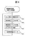
図6は、情報通知処理(無線通信機器)のフローチャートである。
情報通知処理(無線通信機器)は、生成部2002、センサ部204、無線処理部206、送信部2001などが、情報通知処理プログラムを動作させることで処理する。一定時刻が経過するとセンサ部204からセンサ情報を取得し、無線処理部206を経由して、生成部2002がセンサ情報を無線通信パケットとして生成し、送信部2001が生成された無線通信パケットを送信する処理である。
FIG. 6 is a flowchart of the information notification process (wireless communication device).
The information notification process (wireless communication device) is processed by causing the
まず、センサ部からセンサ情報を取得する(ステップ601)。次に生成部が取得したセンサ情報とセンサ情報データベースに格納している過去の差分値から情報通知パケット501を生成する(ステップ602)。生成した情報通知パケット501を、あらかじめ割り当てられているタイムスロットの時刻になれば、送信部がブロードキャストにて送信する(ステップ603)。ここでタイムスロットとは、各端末でパケットの送信タイミング(スロット)が決められていることである。つまり本実施例では、各端末がそれぞれのタイムスロットでパケットを送信する。
First, sensor information is acquired from the sensor unit (step 601). Next, the
送信完了後に、所定の時間内に一定時間待機するため省電力モード(スリープ)に遷移する(ステップ604)。ここで所定の時間とは、ACKが返るより短い時間である。つまり、ACKを待たずにスリープモードにする。そして、一定時間経過すれば省電力モードから通常モードに遷移し、ステップ601に戻る。ACKを待たずにスリープモードにすることにより、送信パケットが100バイト、ACKが5バイトの場合、ACKを待つ時と比べて約1/20程度消費電力を抑えられる。 After the transmission is completed, a transition to the power saving mode (sleep) is made to wait for a predetermined time within a predetermined time (step 604). Here, the predetermined time is a shorter time than when ACK is returned. That is, the sleep mode is set without waiting for ACK. Then, when a certain time elapses, the power saving mode is changed to the normal mode, and the process returns to step 601. By setting the sleep mode without waiting for the ACK, when the transmission packet is 100 bytes and the ACK is 5 bytes, the power consumption can be suppressed by about 1/20 compared to when waiting for the ACK.
図7は、情報通知処理(中継機器)のフローチャートである。
情報通知処理(中継機器)は、センサ部214、無線送受信処理部216、送信部222などが、情報通知処理プログラム207を動作させることで処理する。一定時刻経過後にセンサ部214からセンサ情報を取得し、無線送受信処理部216を経由して、センサ情報を送信部222が無線通信パケットとして送信し、中継情報データベース221にデータがある場合、無線通信パケットに中継情報を付加して送信する処理である。
FIG. 7 is a flowchart of the information notification process (relay device).
The information notification process (relay device) is processed by causing the
まず、センサ部からセンサ情報を取得する(ステップ701)。次に判定部224が中継情報データベース221にデータがあるかどうかを判定する(ステップ702)。データがあると判定した場合、生成部225は、中継情報データベース221から自身のタイムスロットにおいて送信可能なノード数分のノードIDと総積算値を抽出する(ステップ703)。取得したセンサ情報と抽出したノードIDと総積算値から情報通知中継パケット511を生成する(ステップ704)。
First, sensor information is acquired from the sensor unit (step 701). Next, the determination unit 224 determines whether there is data in the relay information database 221 (step 702). If it is determined that there is data, the
生成した情報通知中継パケット511を、送信部222が、あらかじめ割り当てられているタイムスロットの時刻にブロードキャストにて周囲の機器に送信する(ステップ705)。最後に、中継情報データベース221に格納されている情報を全て削除して(ステップ706)、一定時間待機する(ステップ709)。判定部224が中継情報データベース221にデータがないと判定した場合は、情報通知プログラム(無線通信端末)207と同様の振る舞いとなり、取得したセンサ情報とセンサ情報データベースに格納している過去の差分値から情報通知パケット501を生成する(ステップ707)。
生成した情報通知パケット501を、あらかじめ割り当てられているタイムスロットの時刻になれば送信部222は、ブロードキャストにて周囲の機器に送信する(ステップ708)。最後に、一定時間待機し(ステップ709)、一定時間経過すれば、ステップ701に戻る。
The transmission unit 222 transmits the generated information notification relay packet 511 to surrounding devices by broadcasting at a time slot assigned in advance (step 705). Finally, all the information stored in the
When the generated
ここで、ステップ703の送信可能なノード数分のノードIDと総積算値を抽出する方法として、空きタイムスロット分をランダムで抽出する、受信したものから順に抽出する、他の中継機器102からの受信パケットを見て、まだ中継配信されていないノードIDの情報(他中継機器102から受信したパケットを除いた情報)を優先して抽出する、などがある。
Here, as a method of extracting node IDs and total integrated values for the number of nodes that can be transmitted in
また、ステップ706において、子ノード以外のパケットを自身が送信可能な数以上に受信してしまった場合でも、中継情報データベース221のデータは全て削除する。これは、中継パケットのタイムラグを全ノードからのデータ収集間隔以内に抑えることで、データ収集サーバ110で管理している各ノードの送信タイミングから計算して、中継配信時のタイムラグを補正できるようにしている。つまり、中継情報は受信した時刻から1つ前のノードの送信タイミング時間となる。
In
図8は、情報通知受信中継処理のフローチャートである。
情報通知受信中継処理とは、受信部223、判定部224、生成部225、送信部222などが、情報通知受信中継プログラム220を動作させることで処理する。各ノードから無線通信パケットを受信すると、そのノードが子ノードか否かを判断して、子ノードの場合は情報通知プログラム(中継機器)217と同様に無線通信パケットを生成して送信し、子ノードでない場合は、中継情報データベース221に格納する処理である。
FIG. 8 is a flowchart of the information notification reception relay process.
The information notification reception relay process is performed by causing the reception unit 223, the determination unit 224, the
まず、受信部223が、情報通知パケット501を受信する(ステップ801)。判定部224は、情報通知パケットの送信元ノードIDが子ノードであるかどうかを判断する(ステップ802)。生成部225は、送信元ノードIDが子ノードである場合、中継情報データベース221にデータがあるかどうかを判断する(ステップ803)。データがあれば情報通知プログラム(中継機器)207と同様に受信した情報通知パケット501から情報通知中継パケット511を生成し(ステップ804、ステップ805)、あらかじめ割り当てられているタイムスロットの時刻になれば送信部222は、ブロードキャストにて送信し(ステップ806)、送信したノードIDのデータを中継情報データベース221から削除する(ステップ807)。
First, the receiving unit 223 receives the information notification packet 501 (step 801). The determination unit 224 determines whether or not the transmission source node ID of the information notification packet is a child node (step 802). If the transmission source node ID is a child node, the
中継情報データベース221にデータがない場合は、生成部225は、受信した情報通知パケット501の送信元ノードIDを自身のノードIDに変更して(ステップ808)、あらかじめ割り当てられているタイムスロットの時刻になれば送信部222が、ブロードキャストにて送信する(ステップ809)。受信した情報通知パケット501の送信元ノードIDが自分の子ノードでない場合は、受信した情報通知パケット501からノードIDと総積算値を抽出し(ステップ810)、中継情報データベースに格納する(ステップ811)。
When there is no data in the
図9は、パケット転送処理のフローチャートである。
パケット転送処理とは、転送部239などが、パケット転送プログラム237を動作させて処理するものであり、無線通信機器101もしくは中継機器102が送信した無線通信パケットを受信して、通信処理部234を介してデータ収集サーバに送信する処理である。
FIG. 9 is a flowchart of packet transfer processing.
In the packet transfer process, the
まず、情報通知パケット501もしくは情報通知中継パケット511を受信すると(ステップ901)、受信した無線通信パケットをデータ収集サーバ110に転送し(ステップ902)、終了する。
First, when the
図10は、情報受信処理のフローチャートである。
無線基地局から転送されてきた情報通知パケット501もしくは情報通知中継パケット511から必要な情報を抽出し、情報収集データベース119に格納する処理である。
FIG. 10 is a flowchart of the information reception process.
In this process, necessary information is extracted from the
まず、通信処理部206が、情報通知パケット501もしくは情報通知中継パケット511を受信する(ステップ1001)。取得部1002は、パケットの機器IDと、総積算値を取得する(ステップ1002)。受信した無線通信パケットから送信元機器IDと再計算部1003によってカウントされた通信回数に対応づけられた総積算値を情報収集データベース119に格納する(ステップ1003)。送信元機器IDの過去の総積算値が情報収集データベース119に格納されていない場合は(ステップ1004)、再計算部1003が、無線通信パケットの過去の差分値から過去の総積算値を計算し、情報収集データベース119に格納する(ステップ1005)。
First, the
さらに、無線通信パケットが情報通知中継パケット511である場合、他の機器IDの総積算値が情報収集データベース119に格納されている最新のパケットと、自己の機器IDの現在のパケットとの差が一周期以上であるか否かを、予め決められた順番情報(情報収集データベース119)に基づいて判断する(ステップ1006)。一周期以上の場合は、当該機器IDの総積算値を、現在より一周期前の総積算値として、他の機器IDの総積算値も合わせて情報収集データベース119に格納し(ステップ1007)、終了する。ここで、ステップ1007において、現在の時刻より前に複数の時刻における総積算値の情報が格納されていない場合は、現在の時刻より前であり、かつ一番現在の時刻に近い時刻の欄に受信した総積算値を格納する。ステップ1006において一周期未満の場合は、パケットを格納せずに終了する。
Furthermore, when the wireless communication packet is the information notification relay packet 511, the difference between the latest packet in which the total integrated value of other device IDs is stored in the information collection database 119 and the current packet of its own device ID is Whether or not it is one cycle or more is determined based on predetermined order information (information collection database 119) (step 1006). In the case of one cycle or more, the total integrated value of the device ID is stored in the information collection database 119 together with the total integrated value of other device IDs as the total integrated value of one cycle before the current time (step 1007). finish. Here, in
図12(a)(b)は、情報収集データベース119の復元方法を示す図である。
図12(a)は、3rd通信の機器ID2の情報受信処理が終了した後の状態であり、図12(b)は、3rd通信の機器ID3の情報受信処理が終了した後の状態である。
FIGS. 12A and 12B are diagrams showing a method for restoring the information collection database 119.
FIG. 12A shows a state after the information reception process for the
まず、図12(a)について説明する。1st通信において、機器ID1は総積算値1425、機器ID2は総積算値17853と、機器ID3は総積算値5637、機器ID4は総積算値6895いうパケットを受信し、その情報を格納している。2nd通信において、機器ID1は総積算値1493、機器ID3は総積算値5777、機器ID4は総積算値6905であるパケットを受信し、機器ID2についてのパケットは受信しなかったという情報を格納している。3rd通信において、機器ID1は総積算値1450、機器ID2についてのパケットは受信しなかったという情報を格納している。ここで、機器ID2のタイムスロットにおいてパケットを受信しなかった場合は、機器ID2の2nd通信におけるパケット情報は格納されない。なお、2nd通信の機器ID2の総積算値については、2nd通信において機器ID3にも、機器ID4から機器IDmにも3rd通信において機器ID1にも付加されていなかったので、現時点ではパケットロスをしているとする。
First, FIG. 12A will be described. In the 1st communication, a device ID1 receives a total
つぎに図12(b)について説明する。3rd通信において機器ID3が、機器ID3の総積算値が5500であるという情報のほかに、機器ID2の総積算値が17900であるという情報を付加していた場合は、3rd通信における機器ID2の欄に17900という情報を格納する(図12(b)の網掛け部)。
Next, FIG. 12B will be described. In the 3rd communication, when the
また、3rd通信において機器ID3が機器ID2の情報を付加していない場合でも、3rd通信で機器ID4からm、或は4th通信で機器ID1が、機器ID1の総積算値の情報のほかに、機器ID2の総積算値が17900であるという情報を付加していた場合は、3rd通信における機器ID2の欄に17900という情報を格納することができる。また、4th通信で機器ID2が総積算値を受信した場合、パケットに格納されている10分前総積算値が3rd通信の総積算値となり、20分前総積算値が3rd通信の総積算値となり、30分前総積算値が1st通信の総積算値となるので、パケットロスを防ぐことができる。
Even if the
つまり、自己の機器情報以外に、他の機器の情報を含んでいた場合で、現在の時刻より前に複数の時刻における総積算値の情報が格納されていない場合は、現在の時刻より前であり、かつ一番現在の時刻に近い時刻の欄に、受信した総積算値を格納する。 In other words, when information on other devices is included in addition to its own device information, and the total accumulated value information at multiple times is not stored before the current time, the information before the current time. The received total integrated value is stored in the column of time that is present and closest to the current time.
図11は、無線ネットワークシステムにおけるデータ収集のシーケンス図である。
最初に、ノードIDが11である無線通信機器101がセンサ情報を取得し(ステップ1101)、情報通知パケット501を生成する(ステップ1102)。生成した情報通知パケット501を自身の送信可能なタイミングでブロードキャスト送信し(ステップ1103)、すぐにスリープする(ステップ1104)。
FIG. 11 is a sequence diagram of data collection in the wireless network system.
First, the
ノードIDが10である中継機器102はノードID11の無線通信機器101が子ノードであった場合、処理1103の情報通知パケット501を受信すると、まだ中継情報データベース221にデータを保持していないため、送信元ノードIDを自身のノードIDに変更して再ブロードキャストする(ステップ1105)。ノードIDが1023の無線基地局は、情報通知パケットを受信すると、そのまま情報収集サーバ110に転送する(ステップ1106)。情報処理サーバ110は、受信した情報通知パケット501からノードIDと総積算値や差分値などから必要な情報を抽出して、情報収集データベース119に格納する(ステップ1107)。
When the
一方、ノードIDが20である中継機器102はノードID11の無線通信機器101が子ノードでないため、処理1103の情報通知パケット501を受信すると、ノードIDと総積算値を抽出して(ステップ1108)、中継情報データベース221に格納する(ステップ1109)。
On the other hand, when the
次に、ノードIDが20の中継機器102が送信するタイミングになった場合、センサ情報を取得する(ステップ1110)とともに、中継情報データベース221から処理1109で格納したノードIDが10の無線通信機器101の総積算値を取得して(ステップ1111)、情報通知中継パケット511を生成し(ステップ1112)、他の機器に向けてブロードキャスト送信する(ステップ1113)。
Next, when it is time for the
処理1113でブロードキャスト送信した情報通知中継パケット511は、ノードIDが1023の無線基地局が受信し、そのまま情報収集サーバへと転送される(ステップ1114)。情報処理サーバ110は、受信した情報通知中継パケット511からノードIDと総積算値や差分値などから必要な情報を抽出して、情報収集データベース119に格納する(ステップ1115)。
The information notification relay packet 511 broadcasted in the process 1113 is received by the wireless base station having the node ID of 1023 and transferred as it is to the information collection server (step 1114). The
一方、ノードIDが10である中継機器102はノードID10の中継機器101が子ノードでないため、処理1113の情報通知中継パケット511を受信すると、ノードIDと総積算値を抽出して(ステップ1116)、中継情報データベース221に格納する(ステップ1117)。
On the other hand, since the
以上を繰り返すことで、中継機器102を経由して、各ノードの必要な情報のみを冗長に中継配信して、情報収集サーバ110まで届けることで、システムとしてデータ収集の確実性を向上させる。
By repeating the above, only the necessary information of each node is relayed and delivered redundantly via the
また、本実施例では、送信後ACKを待たずにすぐに省電力モードに遷移することで、電池の消費量を抑えることとしている。しかし、ACKを待たないため、無線通信パケットの到達確認ができないが、無線通信パケットがロスした場合でも、情報通知パケット501内の総積算値のみを他のノードから中継配信することで、総積算値だけは冗長にデータ収集サーバ110に送信し、無線通信パケットの到達率を高め、データ収集の確実性を保つものである。さらに、無線通信パケット内の総積算値だけを、中継機器が自身の送信タイミングに合わせて、無線通信パケット内に付加する形で送信することで、中継における無線帯域の圧迫を抑制し、TDMA方式などの無線ネットワークシステムにおいて、タイムスロットを有効に活用することができ、一定時間内により多くの無線通信機器からデータ収集することが可能となる。
Further, in this embodiment, the battery consumption is suppressed by switching to the power saving mode immediately without waiting for ACK after transmission. However, since it does not wait for ACK, the arrival confirmation of the wireless communication packet cannot be confirmed. However, even if the wireless communication packet is lost, only the total accumulated value in the
第一の実施例は、中継機器が子ノードから中継すべきパケットを受信するタイミング以外に、子ノード以外からのパケットであっても受信を許可する、すなわち、送信タイミングずれを許可する場合でも無線通信パケットの到達率を高める、本発明の実施形態であった。 In the first embodiment, reception is permitted even for packets from other than the child node other than the timing when the relay device receives the packet to be relayed from the child node, that is, even when transmission timing deviation is permitted. This is an embodiment of the present invention that increases the arrival rate of communication packets.
第二の実施例では、無線基地局103配下、全ての中継機器及び無線通信機器が正確に時刻同期し、通信タイミングを厳密に管理した場合の実施形態について説明する。
In the second embodiment, an embodiment will be described in which all the relay devices and the wireless communication devices are accurately time-synchronized and the communication timing is strictly managed under the
まず、本実施例にかかる無線ネットワークシステム構成、無線通信機器構成、中継機器構成、無線基地局構成、無線通信パケット構成について説明する。次に、無線通信機器、中継機器、無線基地局の動作概略について説明する。 First, a wireless network system configuration, a wireless communication device configuration, a relay device configuration, a wireless base station configuration, and a wireless communication packet configuration according to the present embodiment will be described. Next, an outline of operations of the wireless communication device, the relay device, and the wireless base station will be described.
本実施例にかかる無線ネットワークシステム構成(図1)、無線通信機器101のハードウェア構成(図2(a))、中継機器102のハードウェア構成(図2(b))、無線基地局103のハードウェア構成(図2(c))、及び、無線通信パケット構成(図5(a)(b))、機器固有情報データベース208、218(図3(a))、基地局固有情報データベース228(図3(b))、センサ情報データベース209、219(図4(a))、情報収集データベース(図4(c))、無線通信パケット構成(図5(a)(b))は実施例1と同様である。
Wireless network system configuration according to the present embodiment (FIG. 1), hardware configuration of wireless communication device 101 (FIG. 2A), hardware configuration of relay device 102 (FIG. 2B),
図13は、本実施例にかかる中継情報データベース221の一例を示す図である。 中継情報データベース221は、中継機器102が子ノード以外の無線通信機器101もしくは中継機器102から受信した無線通信パケットのノードIDと総積算値を格納するデータベースである。
FIG. 13 is a diagram illustrating an example of the
ノードID欄411には、本実施例では、受信した無線通信パケットのオリジナルノードIDを格納する。総積算値欄412には、受信した無線通信パケットの総積算値を格納する。中継結果欄1313には、受信した無線通信パケットが、既定のタイミングで、中継機器によって中継送信されたか否かを判断した結果を格納する。例えば、中継送信されなかった場合には1を格納し、中継送信された場合には0を格納するものとする。これは、本システムが全てのノードが時刻同期して決められたスケジュール通りに通信を行っているため、中継送信すべきノードが、中継送信すべきデータを子ノードから受信するタイミングで受信できなかった場合に、該中継ノードが、本来、中継送信するタイミングで、中継送信失敗を明示的に周囲に通知することにより、周辺ノードが中継結果を把握することができ、該中継結果を中継結果欄1313に格納することにより、実現可能である。
In the node ID column 411, the original node ID of the received wireless communication packet is stored in this embodiment. The total
次に、本実施例にかかる無線基地局、無線中継機器、無線通信機器の動作について説明する。 Next, operations of the radio base station, the radio relay device, and the radio communication device according to the present embodiment will be described.
図14は、無線通信機器が情報通知処理を行うためのフローチャートであり、実施例1の図6に相当する。 FIG. 14 is a flowchart for performing information notification processing by the wireless communication device, and corresponds to FIG. 6 of the first embodiment.
図15は、無線中継機器が情報通知処理を行うためのフローチャートである。 FIG. 15 is a flowchart for the wireless relay device to perform information notification processing.
情報通知処理(中継機器)は、センサ部214、無線送受信処理部216、情報通知処理プログラム217を動作させることで処理する。一定時刻経過後にセンサ部214からセンサ情報を取得し、無線送受信処理部216を経由して、センサ情報を送信部222が無線通信パケットとして送信し、中継情報データベース221にデータがある場合、無線通信パケットに中継情報を付加して送信する。
The information notification process (relay device) is processed by operating the
まず、センサ部からセンサ情報を取得する(ステップ701)。次に判定部224が中継情報データベース221にデータがあるかどうかを判定する(ステップ702)。データがあると判定した場合、ステップ1501に進み、無いと判断した場合は、ステップ707に進む。ステップ1501では、生成部225は、中継情報データベース221から自身のタイムスロットにおいて送信可能なノード数分のノードIDと総積算値を抽出し、パケットを送信する処理を行う。ステップ1501の詳細は図16で説明する。
First, sensor information is acquired from the sensor unit (step 701). Next, the determination unit 224 determines whether there is data in the relay information database 221 (step 702). If it is determined that there is data, the process proceeds to step 1501, and if it is determined that there is no data, the process proceeds to step 707. In
一方、データが無いと判定した場合は実施例1と同様である。 On the other hand, when it is determined that there is no data, it is the same as in the first embodiment.
最後に、一定時間待機し、(ステップ709)一定時間経過すれば、ステップ701に戻る。 Finally, it waits for a certain period of time (step 709), and if a certain period of time has elapsed, it returns to step 701.
図16は、中継すべき情報を選択し、中継送信する処理を示すフローチャートである。中継情報の選択と中継送信する処理は、無線送受信処理部216、送信部222などが、情報通知処理プログラム207を動作させることで処理する。 FIG. 16 is a flowchart showing a process for selecting and relaying information to be relayed. The relay information selection process and the relay transmission process are performed by the wireless transmission / reception processing unit 216, the transmission unit 222, and the like by operating the information notification processing program 207.
次に判定部224が中継情報データベース221にデータがあるかどうかを判定する(ステップ1601)。データがあると判定した場合、データベース221にエントリされているレコード数を判定する。レコード数があらかじめ決められた数、あるいは、送信スロット内で送信可能な数以下である場合、ステップ703に進み、それ以外の場合、ステップ1602に進む。
Next, the determination unit 224 determines whether there is data in the relay information database 221 (step 1601). If it is determined that there is data, the number of records entered in the
ここで、あらかじめ決められた数、及び、自身の送信スロット内で送信可能な数というものは、例えば、タイムスロットが1秒であった場合、送信処理を1秒以内に終了させなければならず、送信開始から送信終了までにかかる時間と通信速度から送信可能な無線パケット長を計算し、情報通知中継パケット511のノード数512以降に続くを決定した値である。
Here, the predetermined number and the number that can be transmitted in its own transmission slot, for example, if the time slot is 1 second, the transmission process must be completed within 1 second. The wireless packet length that can be transmitted is calculated from the time taken from the start of transmission to the end of transmission and the communication speed, and the value following the number of
ステップ703からステップ706までは、実施例1と同様である。
中継情報データベース221のレコード数が送信可能なノード数より多く存在した場合、判定部224はデータベース221の「中継送信失敗」列1313を調べ、(ステップ1602)中継送信を失敗しているものがある場合は、ステップ1603に進み、全て中継送信に成功している場合は、ステップ703に進む。
When the number of records in the
中継送信を失敗しているものがある場合(ステップ1603)、生成部225は、中継情報データベース221から自身のタイムスロットにおいて送信可能なノード数分のノードIDと総積算値を、中継送信失敗しているノードIDを優先して抽出し(ステップ1603)、ステップ704に進む。
If there is one that has failed in relay transmission (step 1603), the
ここで、ステップ703及びステップ1603で送信可能なノード数を超えたデータがデータベース221に存在している場合は、ランダムで抽出する、受信したものから順に抽出する、他の中継機器102からの受信パケットを見て、まだ中継配信されていないノードIDの情報(他中継機器102から受信したパケットを除いた情報)を優先して抽出する、などがある。
Here, when data exceeding the number of nodes that can be transmitted in
図17は、中継機器による情報通知受信中継処理のフローチャートである。 FIG. 17 is a flowchart of the information notification reception relay process by the relay device.
情報通知受信中継処理とは、無線処理部216、判定部224、生成部225等が情報通知受信中継プログラム220を動作させることで処理する。中継器は各ノードから無線通信パケット501或いは511を受信すると、そのノードが子ノードか否かを判断して、子ノードの場合は情報通知プログラム(中継機器)217と同様に無線通信パケットを生成して送信し、子ノードでない場合は、中継情報データベース221に格納する処理である。また、自身が中継すべき情報通知パケットを子ノードから受信するタイムスロットにもかかわらず、子ノードから無線パケットを受信しなかった場合、本来は中継送信するはずの情報通知パケットの代わりに中継送信失敗の情報を送信する。
The information notification reception relay process is performed when the wireless processing unit 216, the determination unit 224, the
まず、無線処理部216が情報通知パケット501を受信する(ステップ801)。判定部224は、現在のタイミングが子ノードから受信すべきタイムスロットであるかどうかを判断し(ステップ1701)、受信すべきタイミングであった場合、情報通知パケットの送信元ノードIDが子ノードであるかどうかを判断する(ステップ802)。生成部225は、送信元ノードIDが子ノードである場合、生成部225は、受信した情報通知パケット501或いは511の送信元ノードIDを自身のノードIDに変更して(ステップ1702)、あらかじめ割り当てられているタイムスロットになれば無線処理部216が、ブロードキャストにて送信する(ステップ1703)。子ノードではない場合は、情報通知パケットを破棄する。
First, the wireless processing unit 216 receives the information notification packet 501 (step 801). The determination unit 224 determines whether or not the current timing is a time slot to be received from the child node (step 1701), and if it is the timing to be received, the transmission source node ID of the information notification packet is the child node. It is determined whether or not there is (step 802). If the transmission source node ID is a child node, the
また、ステップ801、ステップ1701において、中継送信するデータを子ノードから受信するタイムスロットであっても、受信しなかった場合、ある子ノードからの情報通知パケットを中継送信可能なタイムスロットになってもデータがない。この場合は、情報通知パケット501のオリジナルノードIDを該子ノードのIDにし、総積算値507に中継失敗を意味する情報、例えばNULL値のようなものを入れて送信する。これにより、周囲のノードは中継送信に失敗したことが分かり、中継情報データベース221の中継失敗1313に失敗を格納することが可能になる。さらに、無線基地局が該無線パケットを受信することで、無線基地局及びデータ収集サーバにおいて、どの区間で中継送信パケットがロストしたかが判断できる。これは、中継機器が持つ通信ログを格納するメモリ領域の削減効果がある。また、中継送信が頻発し、システムとしては原因究明をしなければならない場合、パケットをロストした通信区間がわかることにより、全てのログを収集する手間を削減する効果がある。
In
ステップ受信した情報通知パケット501あるいは、511の送信元ノードIDが自分の子ノードでない場合、判定部は、積算値がNULL値、すなわち中継送信失敗を通知するパケットである場合、受信した情報通知パケット501からオリジナルノードIDを抽出し(ステップ1707)、中継情報データベースにオリジナルノードIDと中継失敗情報を格納する(ステップ1708)。積算値がNULL値ではない場合受信した情報通知パケット501あるいは、511からオリジナルノードIDと総積算値を抽出し(ステップ1705)、中継情報データベースに格納する(ステップ1706)。 以上を繰り返すことで、中継機器102を経由して、各ノードの必要な情報のみを冗長に中継配信して、情報収集サーバ110まで届ける際、無線通信に失敗した送信元ノードIDの情報を優先的に選択して冗長中継配信することで、システムとしてデータ収集の確実性を向上することが可能になる。
If the transmission source node ID of the received
本実施例では、各中継器が無線失敗情報を自発的に送信するものであったが、本発明では、中継送信失敗をネットワーク内の無線中継器に通知する方法は、これに限るものではない。周囲の中継機器において、中継送信結果が把握できればよい。例えば、無線基地局から受信できなかったオリジナルノードIDの一覧を全無線中継機器に配信する方法により、通知してもよい。本実施例の方法は、無線通信帯域が十分に確保できない場合に、失敗通知のための無線パケットを新たに追加する必要がないため、効率的に無線帯域を利用することが可能となる。 In this embodiment, each repeater voluntarily transmits wireless failure information. However, in the present invention, the method of notifying the wireless repeater in the network of the relay transmission failure is not limited to this. . It is only necessary that the relay transmission result can be grasped in the surrounding relay devices. For example, the list of original node IDs that could not be received from the wireless base station may be notified by a method of distributing to all wireless relay devices. According to the method of this embodiment, when it is not possible to secure a sufficient wireless communication band, it is not necessary to newly add a wireless packet for failure notification, so that the wireless band can be used efficiently.
また、本実施例では、中継送信に失敗したノードを優先的に選択したが、記憶しているノード間の優先順位を考慮してデータを選択するものであって、優先順位の決定はこれに限らない。例えば、自ノードの親ノードを優先的に選択する等、ノードの優先順は他方法で決めてもよい。 Further, in this embodiment, the node that failed in relay transmission was preferentially selected, but the data is selected in consideration of the priority order between the stored nodes. Not exclusively. For example, the priority order of nodes may be determined by other methods, such as preferentially selecting the parent node of the own node.
101 無線通信機器
102 中継機器
103 無線基地局
104 ネットワーク
110 データ収集サーバ
114 出力部
115 通信処理部
116 入力部
118 情報受信プログラム
119 情報収集データベース
207 情報通知プログラム(無線通信機器)
217 情報通知プログラム(中継機器)
220 情報通知受信中継プログラム
221 中継情報データベース
237 パケット転送プログラム
238 基地局固有情報データベース
501 情報通知パケット
511 情報通知中継パケット
204、214 センサ部
208、218 機器固有情報データベース
209、219 センサ情報データベース
203、213、233 表示部
206、216、236 無線処理部
111、205、215、225 主記憶部
112、202、212、232 補助記憶部
113、201、211、231 中央制御部
101 Wireless communication equipment
102 Relay equipment
103 radio base station
104 network
110 Data collection server
114 Output section
115 Communication processor
116 Input section
118 Information reception program
119 Information collection database
207 Information notification program (wireless communication equipment)
217 Information notification program (relay device)
220 Information notification reception relay program
221 Relay information database
237 Packet transfer program
238 Base Station Specific Information Database
501 Information notification packet
511 Information notification relay packet
204, 214 Sensor unit
208, 218 Device specific information database
209, 219 Sensor information database
203, 213, 233 Display
206, 216, 236 Wireless processor
111, 205, 215, 225 Main memory
112, 202, 212, 232 Auxiliary storage
113, 201, 211, 231 Central control unit
Claims (17)
前記パケットを受信し、
受信した前記パケットの送信元が自己の子ノードであるかを、前記パケットの送信元ノードIDと、自己のノードID情報を記録するリストとを対応付けて判定し、
前記判定の結果に基づいて前記パケットから新たなパケットを生成し、
前記パケットの送信元は子ノードでないと判定した場合、
前記パケットのIDと前記パケットに含まれる所定のデータとを、自己の子ノードから送信されてくるパケットに付加することで、新たに他の子ノード付加パケットを前記新たなパケットとして生成することを特徴とするパケット中継方法。 A packet relay method for receiving a packet transmitted from a wireless communication device, generating a new packet and transmitting the packet,
Receiving the packet;
Whether the transmission source of the received packet is its own child node is determined by associating the transmission source node ID of the packet with a list recording its own node ID information,
Generating a new packet from the packet based on the result of the determination;
If it is determined that the source of the packet is not a child node,
By adding the packet ID and predetermined data included in the packet to a packet transmitted from its own child node, a new child node addition packet is newly generated as the new packet. A characteristic packet relay method.
前記パケットを受信する受信部と、
受信した前記パケットの送信元が自己の子ノードであるかを、前記パケットの送信元ノードIDと、自己のノードID情報を記録するリストとを対応付けて判定する判定部と、前記判定の結果に基づいて前記パケットから新たなパケットを生成する生成部とを備え、
前記判定部が前記パケットの送信元は子ノードでないと判定した場合、
前記生成部は、前記パケットのIDと前記パケットに含まれる所定のデータとを、自己の子ノードから送信されてくるパケットに付加することで、新たに他の子ノード付加パケットを前記新たなパケットとして生成することを特徴とするパケット中継装置。 A packet relay device that receives a packet from a wireless communication device, generates a new packet, and transmits the packet.
A receiving unit for receiving the packet;
A determination unit that determines whether the transmission source of the received packet is a child node of the packet in association with the transmission source node ID of the packet and a list that records the node ID information of the packet; and a result of the determination and a generation unit for generating a new packet from the packet based on,
When the determination unit determines that the source of the packet is not a child node,
The generation unit adds another child node additional packet to the new packet by adding the ID of the packet and the predetermined data included in the packet to the packet transmitted from its child node. A packet relay device generated as:
前記生成部が生成する前記パケットの送信元ノードを書き換えたパケットとは、
前記判定部が前記パケットの送信元は子ノードであると判定した場合における、
前記生成部が前記パケットの送信元ノードIDを自己のノードIDに書き換えたパケットである送信元書き換えパケットであって、
前記送信元書き換えパケット又は前記他の子ノード付加パケットを前記新たなパケットとして送信する送信部を更に備えることを特徴とするパケット中継装置。 The packet relay device according to claim 2 ,
A packet in which the source node of the packet generated by the generation unit is rewritten is:
When the determination unit determines that the transmission source of the packet is a child node,
The generation unit is a source rewrite packet that is a packet in which the source node ID of the packet is rewritten to its own node ID,
A packet relay apparatus, further comprising: a transmission unit that transmits the transmission source rewrite packet or the other child node addition packet as the new packet.
パケットを送信する前記無線通信機器は、パケットの送信完了情報を受信した後にスリープモードにすることを特徴とするパケット中継装置。 In the packet relay device according to any one of claims 2 and 3 ,
The wireless communication device that transmits a packet enters a sleep mode after receiving packet transmission completion information.
前記判定部が前記パケットの送信元は子ノードであると判定した場合、
前記生成部は、前記パケットの送信元ノードIDを自己のノードIDに書き換えたパケットである送信元書き換えパケットを前記新たなパケットとして生成し、
前記送信部は前記新たなパケットを送信することを特徴とするパケット中継装置。 The packet relay device according to claim 2 ,
When the determination unit determines that the transmission source of the packet is a child node,
The generation unit generates a source rewrite packet that is a packet in which the source node ID of the packet is rewritten to its own node ID as the new packet,
The packet relay device, wherein the transmission unit transmits the new packet.
前記パケットのIDと前記パケットに含まれる所定のデータとを含む付加情報を格納する格納部を更に備え、
前記生成部は、前記送信元書き換えパケットに前記付加情報を付加し前記他の子ノード付加パケットを生成し、
前記送信部は、前記他の子ノード付加パケットを送信することを特徴とするパケット中継装置。 In the packet relay device according to claim 2 or 3 ,
A storage unit for storing additional information including the ID of the packet and predetermined data included in the packet;
The generation unit adds the additional information to the source rewrite packet to generate the other child node additional packet,
The packet relay device, wherein the transmission unit transmits the other child node addition packet.
前記生成部は、
前記判定部が子ノードでないと判定した場合、
送信可能なパケット容量に含まれる空き容量に基づいて前記他の子ノード付加パケットを生成することを特徴とするパケット中継装置。 In the packet relay device according to any one of claims 2 to 6 ,
The generator is
When it is determined that the determination unit is not a child node,
A packet relay apparatus that generates the other child node additional packet based on a free capacity included in a transmittable packet capacity.
前記パケットは、前記所定のデータと、前記無線通信機器が各時間帯において前記無線通信機器に対応付けられたセンシング装置がセンシングした電力量である値とを含むパケットであって、
前記所定のデータとは、前記各時間帯においてセンシングした値を足した総積算値であることを特徴とするパケット中継装置。 In the packet relay device according to any one of claims 2 , 3 , 5 , and 6 ,
The packet is a packet including the predetermined data and a value that is a power amount sensed by a sensing device associated with the wireless communication device in each time zone by the wireless communication device,
The packet relay apparatus according to claim 1, wherein the predetermined data is a total integrated value obtained by adding values sensed in each time period.
前記パケット中継装置における前記送信部は、前記新たなパケットを前記中継基地局に向けて送信することを特徴とするパケット中継システム。 In the packet relay system using the packet relay device according to claim 3 , a wireless terminal device that transmits a packet, and a relay base station that collects the packet,
The packet relay system, wherein the transmission unit in the packet relay device transmits the new packet to the relay base station.
さらに、中継基地局から前記新たなパケットを受信するデータ収集サーバを備え、
前記データ収集サーバは、
前記パケットを受信する受信部と、
前記パケットが子ノードから来たパケットである場合は、送信元ノードに対応する機器IDであり、受信した時刻の欄に、パケット情報を格納し、
前記パケットが子ノードでない他ノードから来たパケットである場合は、前記他ノードのデータベースにおいて格納されているデータの最新時刻と、受信した時刻とを比較し、時間差が一周期以上であれば、受信した前記他ノードのパケット情報を受信した時刻より前であり、かつ一番現在の時刻に近い時刻の欄に、前のパケット情報として格納する格納部を備えることを特徴とするパケット中継システム The packet relay system according to claim 9 , wherein
Furthermore, a data collection server for receiving the new packet from the relay base station,
The data collection server
A receiving unit for receiving the packet;
If the packet is a packet coming from a child node, it is a device ID corresponding to the source node, and stores the packet information in the received time column,
If the packet is a packet coming from another node that is not a child node, the latest time of data stored in the database of the other node is compared with the received time, and if the time difference is one cycle or more, A packet relay system comprising a storage unit that stores the previous packet information in a time field that is earlier than the time when the received packet information of the other node is received and that is closest to the current time
送信可能なパケット容量に含まれる空き容量に基づいて前記他の子ノード付加パケットを生成する際、付加すべき子ノードの優先順位に従って、パケットを生成することを特徴とするパケット中継方法。 The packet relay method according to claim 1 ,
A packet relay method, comprising: generating a packet according to a priority of a child node to be added when generating the other child node additional packet based on a free capacity included in a transmittable packet capacity.
中継送信すべき時間に、事前に子ノードから中継すべきデータを受信していないと判定した場合、子ノードからの中継送信に失敗したことを通知するパケット中継方法。 The packet relay method according to claim 1 ,
A packet relay method for notifying that relay transmission from a child node has failed when it is determined that the data to be relayed from the child node is not received in advance at the time to be relayed.
送信可能なパケット容量に含まれる空き容量に基づいて前記他の子ノード付加パケットを生成する際、付加すべき子ノードの優先順位に従って、パケットを生成することを特徴とするパケット中継装置。 The packet relay device according to claim 7 ,
A packet relay device characterized in that, when generating another child node additional packet based on a free capacity included in a transmittable packet capacity, the packet is generated in accordance with the priority order of the child nodes to be added.
中継送信すべき時間に、事前に子ノードから中継すべきデータを受信していないと判定した場合、子ノードからの中継送信に失敗したことを通知するパケット中継装置。 The packet relay device according to claim 7 ,
A packet relay device for notifying that relay transmission from a child node has failed when it is determined that data to be relayed from the child node is not received in advance at the time to be relayed.
前記中継送信に失敗したこと通知するパケットを受信したノードは、中継送信に失敗したノード情報と失敗した結果を記憶することを特徴とするパケット中継装置。 The packet relay device according to claim 7 ,
A node that receives a packet notifying that the relay transmission has failed stores node information of the relay transmission failure and a result of the failure.
前記中継送信に失敗したノードの優先順位を最も高くすることを特徴とするパケット中継装置。 The packet relay apparatus according to claim 1 3,
A packet relay apparatus characterized in that the highest priority is given to a node that has failed in the relay transmission.
自ノードの親ノードの優先順位を最も高くすることを特徴とするパケット中継装置。 The packet relay apparatus according to claim 1 3,
A packet relay apparatus characterized in that the priority order of a parent node of its own node is made highest.
Priority Applications (1)
| Application Number | Priority Date | Filing Date | Title |
|---|---|---|---|
| JP2011098948A JP5560230B2 (en) | 2010-10-04 | 2011-04-27 | Packet relay method, packet relay apparatus, and packet relay system. |
Applications Claiming Priority (3)
| Application Number | Priority Date | Filing Date | Title |
|---|---|---|---|
| JP2010224472 | 2010-10-04 | ||
| JP2010224472 | 2010-10-04 | ||
| JP2011098948A JP5560230B2 (en) | 2010-10-04 | 2011-04-27 | Packet relay method, packet relay apparatus, and packet relay system. |
Publications (2)
| Publication Number | Publication Date |
|---|---|
| JP2012100243A JP2012100243A (en) | 2012-05-24 |
| JP5560230B2 true JP5560230B2 (en) | 2014-07-23 |
Family
ID=46391623
Family Applications (1)
| Application Number | Title | Priority Date | Filing Date |
|---|---|---|---|
| JP2011098948A Active JP5560230B2 (en) | 2010-10-04 | 2011-04-27 | Packet relay method, packet relay apparatus, and packet relay system. |
Country Status (1)
| Country | Link |
|---|---|
| JP (1) | JP5560230B2 (en) |
Families Citing this family (7)
| Publication number | Priority date | Publication date | Assignee | Title |
|---|---|---|---|---|
| JP6608122B2 (en) * | 2012-10-10 | 2019-11-20 | 京セラ株式会社 | Mobile communication system and mobile communication terminal |
| JP5648165B2 (en) * | 2013-06-10 | 2015-01-07 | 株式会社ベイビッグ | Wireless terminal, wireless communication system, and wireless communication method |
| JP6282840B2 (en) * | 2013-10-29 | 2018-02-21 | シャープ株式会社 | Wireless communication apparatus and wireless information collecting system |
| JP6291848B2 (en) * | 2014-01-10 | 2018-03-14 | 住友電気工業株式会社 | Management system, management device, sensor, management method, and management program |
| JP6447230B2 (en) * | 2015-02-24 | 2019-01-09 | 沖電気工業株式会社 | Data collection method, data collection system, and communication apparatus |
| JP6523112B2 (en) * | 2015-09-11 | 2019-05-29 | 株式会社東芝 | Communication apparatus, relay determination method and relay determination program |
| JP6701731B2 (en) * | 2015-12-29 | 2020-05-27 | 三菱電機株式会社 | Communication system, communication unit, and communication method |
Family Cites Families (5)
| Publication number | Priority date | Publication date | Assignee | Title |
|---|---|---|---|---|
| JP2003134033A (en) * | 2001-10-24 | 2003-05-09 | Fujitsu Ltd | System for communication between mobile objects |
| JP2007019574A (en) * | 2005-07-05 | 2007-01-25 | Matsushita Electric Ind Co Ltd | Radio ad hoc communication method |
| JP2007274303A (en) * | 2006-03-31 | 2007-10-18 | Matsushita Electric Works Ltd | Wireless system |
| JP4818066B2 (en) * | 2006-10-23 | 2011-11-16 | パナソニック株式会社 | Wireless meter reading system and wireless meter reading method |
| JP4871154B2 (en) * | 2007-01-31 | 2012-02-08 | 株式会社日立製作所 | Wireless communication network system, network construction method, center station, relay station, terminal station, and program thereof |
-
2011
- 2011-04-27 JP JP2011098948A patent/JP5560230B2/en active Active
Also Published As
| Publication number | Publication date |
|---|---|
| JP2012100243A (en) | 2012-05-24 |
Similar Documents
| Publication | Publication Date | Title |
|---|---|---|
| JP5560230B2 (en) | Packet relay method, packet relay apparatus, and packet relay system. | |
| Villas et al. | DRINA: A lightweight and reliable routing approach for in-network aggregation in wireless sensor networks | |
| Barrenetxea et al. | Sensorscope: Out-of-the-box environmental monitoring | |
| Huang et al. | CORD: Energy-efficient reliable bulk data dissemination in sensor networks | |
| Petrioli et al. | ALBA-R: Load-balancing geographic routing around connectivity holes in wireless sensor networks | |
| CN103118439B (en) | based on the data fusion method of sensor network node universal middleware | |
| US20150109926A1 (en) | Content centric and load-balancing aware dynamic data aggregation | |
| US20110002251A1 (en) | Time synchronization and routing method in wireless sensor network, and apparatus for enabling the method | |
| US20140232555A1 (en) | Wireless sensor networks | |
| CN108235403A (en) | Collection of energy sensor network, collection of energy node and method | |
| US20180176914A1 (en) | Communication terminal and wireless communication system | |
| JPWO2012132133A1 (en) | Receiver and communication system and in-store equipment monitoring system | |
| US10080107B2 (en) | Topographical display generator for ad hoc network | |
| JP5766503B2 (en) | Wireless management system, wireless terminal device, and transmission management method | |
| JP2021100269A (en) | Wireless sensor system, wireless terminal device, communication control method, and communication control program | |
| JP5875696B2 (en) | Data distribution system, distribution device, terminal device, and data distribution method | |
| WO2009008681A2 (en) | Time synchronization and routing method in wireless sensor network, and apparatus for enabling the method | |
| Turau et al. | The heathland experiment: Results and experiences | |
| JP5425614B2 (en) | Time synchronization method, control system, and measuring apparatus | |
| JP5484865B2 (en) | Communications system | |
| CN104813716A (en) | Method for transmitting and receiving data | |
| WO2015015562A1 (en) | Wireless data collection system, and wireless data collection method | |
| CN101478826B (en) | Communication scheduling method and system for wireless sensor network | |
| US9319279B2 (en) | Topographical display generator for ad hoc network | |
| Atto et al. | Routing Protocols for Structural Health Monitoring of Bridges Using Wireless Sensor Networks. |
Legal Events
| Date | Code | Title | Description |
|---|---|---|---|
| RD04 | Notification of resignation of power of attorney |
Free format text: JAPANESE INTERMEDIATE CODE: A7424 Effective date: 20120522 |
|
| A621 | Written request for application examination |
Free format text: JAPANESE INTERMEDIATE CODE: A621 Effective date: 20130318 |
|
| A521 | Written amendment |
Free format text: JAPANESE INTERMEDIATE CODE: A523 Effective date: 20130318 |
|
| A977 | Report on retrieval |
Free format text: JAPANESE INTERMEDIATE CODE: A971007 Effective date: 20140121 |
|
| A131 | Notification of reasons for refusal |
Free format text: JAPANESE INTERMEDIATE CODE: A131 Effective date: 20140304 |
|
| A521 | Written amendment |
Free format text: JAPANESE INTERMEDIATE CODE: A523 Effective date: 20140417 |
|
| TRDD | Decision of grant or rejection written | ||
| A01 | Written decision to grant a patent or to grant a registration (utility model) |
Free format text: JAPANESE INTERMEDIATE CODE: A01 Effective date: 20140513 |
|
| A61 | First payment of annual fees (during grant procedure) |
Free format text: JAPANESE INTERMEDIATE CODE: A61 Effective date: 20140609 |
|
| R150 | Certificate of patent or registration of utility model |
Ref document number: 5560230 Country of ref document: JP Free format text: JAPANESE INTERMEDIATE CODE: R150 |