JP5559314B2 - Underwater dry distribution converter - Google Patents
Underwater dry distribution converter Download PDFInfo
- Publication number
- JP5559314B2 JP5559314B2 JP2012511105A JP2012511105A JP5559314B2 JP 5559314 B2 JP5559314 B2 JP 5559314B2 JP 2012511105 A JP2012511105 A JP 2012511105A JP 2012511105 A JP2012511105 A JP 2012511105A JP 5559314 B2 JP5559314 B2 JP 5559314B2
- Authority
- JP
- Japan
- Prior art keywords
- converter
- transducer
- core
- voltage winding
- winding
- Prior art date
- Legal status (The legal status is an assumption and is not a legal conclusion. Google has not performed a legal analysis and makes no representation as to the accuracy of the status listed.)
- Expired - Fee Related
Links
- 238000009826 distribution Methods 0.000 title claims description 21
- 238000004804 winding Methods 0.000 claims description 73
- 238000010292 electrical insulation Methods 0.000 claims description 21
- 238000001816 cooling Methods 0.000 claims description 11
- 239000007787 solid Substances 0.000 claims description 11
- XLYOFNOQVPJJNP-UHFFFAOYSA-N water Substances O XLYOFNOQVPJJNP-UHFFFAOYSA-N 0.000 claims description 10
- 239000007788 liquid Substances 0.000 claims description 9
- 239000000463 material Substances 0.000 claims description 9
- 239000011810 insulating material Substances 0.000 claims description 5
- 230000015572 biosynthetic process Effects 0.000 claims description 4
- 238000006243 chemical reaction Methods 0.000 claims description 4
- 239000011347 resin Substances 0.000 claims description 4
- 229920005989 resin Polymers 0.000 claims description 4
- 239000003365 glass fiber Substances 0.000 claims description 2
- 229920001296 polysiloxane Polymers 0.000 claims description 2
- 239000003921 oil Substances 0.000 description 24
- 238000009413 insulation Methods 0.000 description 16
- 239000003570 air Substances 0.000 description 9
- 239000004020 conductor Substances 0.000 description 5
- 238000004880 explosion Methods 0.000 description 5
- 238000009434 installation Methods 0.000 description 5
- 239000002245 particle Substances 0.000 description 5
- 238000011109 contamination Methods 0.000 description 4
- 230000000694 effects Effects 0.000 description 4
- 239000000126 substance Substances 0.000 description 4
- 230000000903 blocking effect Effects 0.000 description 3
- 230000008878 coupling Effects 0.000 description 3
- 238000010168 coupling process Methods 0.000 description 3
- 238000005859 coupling reaction Methods 0.000 description 3
- 238000010586 diagram Methods 0.000 description 3
- 230000017525 heat dissipation Effects 0.000 description 3
- 238000004519 manufacturing process Methods 0.000 description 3
- 238000000034 method Methods 0.000 description 3
- 230000009467 reduction Effects 0.000 description 3
- 239000012080 ambient air Substances 0.000 description 2
- 230000005540 biological transmission Effects 0.000 description 2
- 230000008859 change Effects 0.000 description 2
- 238000010276 construction Methods 0.000 description 2
- 239000003673 groundwater Substances 0.000 description 2
- 238000002955 isolation Methods 0.000 description 2
- 238000012423 maintenance Methods 0.000 description 2
- 239000002184 metal Substances 0.000 description 2
- 229910052751 metal Inorganic materials 0.000 description 2
- 238000000926 separation method Methods 0.000 description 2
- 239000011343 solid material Substances 0.000 description 2
- XEEYBQQBJWHFJM-UHFFFAOYSA-N Iron Chemical group [Fe] XEEYBQQBJWHFJM-UHFFFAOYSA-N 0.000 description 1
- 230000008901 benefit Effects 0.000 description 1
- 238000004140 cleaning Methods 0.000 description 1
- 239000011248 coating agent Substances 0.000 description 1
- 238000000576 coating method Methods 0.000 description 1
- 238000009833 condensation Methods 0.000 description 1
- 230000005494 condensation Effects 0.000 description 1
- 230000007797 corrosion Effects 0.000 description 1
- 238000005260 corrosion Methods 0.000 description 1
- 230000006866 deterioration Effects 0.000 description 1
- 230000029087 digestion Effects 0.000 description 1
- 239000000428 dust Substances 0.000 description 1
- 230000005684 electric field Effects 0.000 description 1
- 239000003344 environmental pollutant Substances 0.000 description 1
- 238000003912 environmental pollution Methods 0.000 description 1
- 238000007689 inspection Methods 0.000 description 1
- 239000012774 insulation material Substances 0.000 description 1
- 230000007257 malfunction Effects 0.000 description 1
- 239000000203 mixture Substances 0.000 description 1
- 230000003071 parasitic effect Effects 0.000 description 1
- 238000005192 partition Methods 0.000 description 1
- 230000000149 penetrating effect Effects 0.000 description 1
- 231100000719 pollutant Toxicity 0.000 description 1
- -1 polyethylene terephthalate Polymers 0.000 description 1
- 229920000139 polyethylene terephthalate Polymers 0.000 description 1
- 239000005020 polyethylene terephthalate Substances 0.000 description 1
- 230000008569 process Effects 0.000 description 1
- 230000001681 protective effect Effects 0.000 description 1
- 239000002689 soil Substances 0.000 description 1
- 239000000725 suspension Substances 0.000 description 1
Images


Classifications
-
- H—ELECTRICITY
- H01—ELECTRIC ELEMENTS
- H01F—MAGNETS; INDUCTANCES; TRANSFORMERS; SELECTION OF MATERIALS FOR THEIR MAGNETIC PROPERTIES
- H01F27/00—Details of transformers or inductances, in general
- H01F27/28—Coils; Windings; Conductive connections
- H01F27/32—Insulating of coils, windings, or parts thereof
- H01F27/324—Insulation between coil and core, between different winding sections, around the coil; Other insulation structures
Description
本発明は、特に地下又は水中の分配設備又は内部設備もしくは外部設備で用いるように設計された、固体絶縁の単相又は三相の分配電気変換器に関する。 The present invention relates to a solid-insulated single-phase or three-phase distribution electrical converter designed specifically for use in underground or underwater distribution facilities or internal or external facilities.
最新技術分野で公知のように、変換器は電力の分配に用いられ、生成場所から消費領域に運ぶのに適している電流及び電圧への電力の変換を可能とする。何十、何百又は何千キロメートルの長距離にわたる電力の伝送において、電気ケーブルの電気抵抗によって生じる電力損失を低減するために、変換器により電圧を上げるのが一般的な方法である。電力の伝送は消費場所の近くまで高電圧下で行われ、また変換器によってその電圧は利用者の装置に適した値に減少される。かかる電圧レベルの減少は、電力消費の中心近くに設置される変換器を用いて幾つかの段階で行われる。これらの変換器の物理的な設置は、柱に固定して空中にしてもよいし、敷地の内部設備内もしくは外部設備内にしてもよいし、または地下設備内にしてもよい。 As is known in the state of the art, converters are used to distribute power and allow the conversion of power into currents and voltages that are suitable for delivery from the production location to the consumption area. In the transmission of power over long distances of tens, hundreds or thousands of kilometers, it is common practice to increase the voltage with a converter in order to reduce the power loss caused by the electrical resistance of the electrical cable. The transmission of power takes place under high voltage close to the place of consumption, and the converter reduces the voltage to a value suitable for the user's device. Such voltage level reduction is done in several stages using a converter installed near the center of power consumption. These transducers may be physically installed in the air by being fixed to a pillar, in an internal facility of the site, in an external facility, or in an underground facility.
都会では、地下の分配ネットワークを介して電力の分配を行うのが一般的な方法である。地下ネットワークを介した電力の分配においては、変換器は地下室に設置される。地下ネットワーク用の分配変換器は独自の特性を持つ。その特性は、例えば、ブラジルにおいてABNT規格のNBR9369、地下の変換器の電気的特性及び機械的特性−標準化により定義されている。地下ネットワーク用の分配変換器のための他の国際的な規格は、例えば「ANSI C57.12.24−2000、地下タイプ変換器 三相分配変換器、2500kVA以下、高電圧34500GrdY/19920ボルト以下、低電圧480ボルト以下(必要条件)についての規格」である。地下ネットワークに設置された変換器は水中用とすべきである。 In cities, it is common practice to distribute power through underground distribution networks. For power distribution via the underground network, the converter is installed in the basement. Distribution converters for underground networks have unique characteristics. Its properties are defined, for example, by the ABNT standard NBR 9369, the electrical and mechanical properties of underground transducers-standardization in Brazil. Other international standards for distribution converters for underground networks are, for example, “ANSI C57.12.24-2000, underground type converter three-phase distribution converter, 2500 kVA or less, high voltage 34500 GrdY / 19920 volts or less, “Standard for low voltage of 480 volts or less (requirement)”. Transducers installed in the underground network should be for underwater use.
変換器は、構造的なタイプに従って、乾式変換器と絶縁液体に浸された変換器に分類される。変換器の多数を占めている、水中用変換器は、絶縁液体に浸される。ここで、その絶縁液体をその化学成分にかかわらずオイルと定義する。ブラジルの規格でカバーされる水中用変換器は、200kVAから2500kVAの割合の電力範囲を有する。 Transducers are classified according to their structural type: dry transducers and transducers immersed in insulating liquid. Submersible transducers, which occupy a large number of transducers, are immersed in an insulating liquid. Here, the insulating liquid is defined as oil regardless of its chemical composition. Underwater transducers covered by the Brazilian standards have a power range of 200 kVA to 2500 kVA.
一般に変換器は、高電圧巻線、低電圧巻線、磁気の流れの循環用の鉄のコア、巻線間の結合部及び結合端子を備える。これらの部品は全て金属製のタンク内部に格納され、オイル中に浸される。そのタンクを介して内部部品を外部結合端子とつなぐためにブッシングが用いられる。 In general, the converter comprises a high voltage winding, a low voltage winding, an iron core for circulation of magnetic flow, a coupling between the windings and a coupling terminal. All these parts are stored inside a metal tank and immersed in oil. A bushing is used to connect the internal part to the external coupling terminal via the tank.
物理法則に従い、変換器の変換関係は巻線間のらせんの関係により与えられる。らせんは、コアの外周を取り囲む、コアの周りの導電物質により形成される。絶縁液体をもつ変換器において、コアの周りのらせんを形成する物質は、巻線導体、巻線の絶縁物質及び絶縁オイルである。 According to the laws of physics, the conversion relationship of the transducer is given by the spiral relationship between the windings. The helix is formed by a conductive material around the core that surrounds the outer periphery of the core. In a transducer with insulating liquid, the materials that form the helix around the core are the winding conductor, the insulating material of the winding and the insulating oil.
絶縁液体内の変換器は、変換器の能動部品及び絶縁オイルを収容するタンクを有する。オイルは、オイルに浸透している他の物質とともに、変換器の電圧を受ける部品とタンクの間の電気絶縁素子の機能を果たす。また、オイルは、巻線及びコアに生じた熱をタンクの冷却面及びラジエーターの冷却面に伝え、運ぶ冷却素子の機能を果たす。 The transducer in the insulating liquid has a tank that houses the active components of the transducer and the insulating oil. The oil, together with other substances penetrating the oil, serves as an electrical isolation element between the tank and the component that receives the voltage of the transducer. The oil also functions as a cooling element that transfers heat generated in the winding and the core to the cooling surface of the tank and the cooling surface of the radiator.
電圧を受ける部品の間で必要な絶縁を得るために、絶縁物質は、適切な間隔、厚さ及び形で用いられ、適合した製造工程で作られる。その実行方法及び電圧を受ける部品に用いられる物質のタイプは、絶縁すべき上記のポイントで想定される電界強度に依存する。 In order to obtain the necessary insulation between the components subjected to the voltage, the insulating material is used in suitable spacing, thickness and shape and made in a suitable manufacturing process. The method of execution and the type of material used for the component that is subjected to the voltage depends on the electric field strength assumed at the above point to be insulated.
これらのオイル内の変換器は、世界中で広く用いられているが、次に記載する問題を有する。 These in-oil converters are widely used throughout the world, but have the following problems.
その化学的条件で用いられる絶縁オイルは、利用可能な幾つかのタイプがあるが、多かれ少なかれ汚染物質であり、土壌に浸透することも地下水を汚染することもないように適切に扱われるべきである。 Insulating oils used in their chemical conditions are available in several types, but more or less are pollutants and should be handled appropriately so that they do not penetrate the soil or contaminate groundwater. is there.
オイルで満たされたタンク内部に変圧器の能動部品が入ると、内部障害、過充電または外部障害にも起因した結果として、タンクの内部圧力が増大する。内部圧力の上昇は、火災から又は火災なしでタンクの爆発を引き起こし、財産及び人の損害の危険性を伴う。その危険性を低減するために、オイル内の変換器は規格に従って安全なデバイスを有さなければならない。これにより危険性を低減することはできるが、除去することはできない。 When active parts of the transformer enter the tank filled with oil, the internal pressure of the tank increases as a result of internal faults, overcharge or external faults. An increase in internal pressure causes a tank explosion from or without a fire, with the risk of property and personal damage. In order to reduce that risk, the converter in oil must have a safe device according to the standard. While this can reduce the risk, it cannot be removed.
このタイプの変換器は、継続的なメンテナンスが必要であり、オイルの水位とオイルの現在の状態を確認する定期的な検査を必要とする。例えば、その確認中におけるオイルの水位の減少の形跡は、漏れの発生を意味する。かかる許容レベルを超えたオイルの水位の減少は、電気絶縁を損ない、その結果として変換器の絶縁を損なう。想定外のオイルの特性の任意の変化は、オイルの劣化、汚染、湿気の混入又は変換器の動作の狂いを意味し、その活動を損なう。 This type of transducer requires continuous maintenance and requires regular inspection to check the oil level and the current state of the oil. For example, evidence of a decrease in the oil level during the check means that a leak has occurred. A reduction in the oil level above such an acceptable level will damage the electrical insulation and consequently the insulation of the transducer. Any unexpected change in the characteristics of the oil means oil deterioration, contamination, moisture contamination, or malfunction of the transducer, impairing its activity.
オイル内の水中用変換器は、高価であり、複雑な建設工程を有し、変換器の爆発に耐性があり、且つ変換器のオイルの封じ込め用のシステムをもつ、特殊な施工に係る地下室に設置される。 Submersible transducers in oil are expensive, have complex construction processes, are resistant to explosions in transducers, and have a system for containment of transducer oils. Installed.
乾式変換器は、タンク内部に閉じ込められたオイルを持たず、変換器のオイルの漏れ又は爆発の発生による、爆発の危険性も環境汚染の危険性も被らない。 Dry converters do not have oil trapped inside the tank and do not suffer the risk of explosion or environmental pollution due to the leakage of the converter oil or the occurrence of an explosion.
例えば、ブラジルの規格「NBR10295 乾式電力変換器」又は例えば「IEC600076 電力変換器−パート2乾式タイプ」又は「IEEE C57.12.01 固体鋳造(Solid-Cast)及び/又は樹脂封入巻線を含む、乾式タイプ分配及び電力変換器のための一般要件についての規格」等の国際規格に記載されている乾式分配変換器は、保護下で設置されるべき乾式変換器である。
For example, including the Brazilian standard “NBR10295 dry power converter” or “IEC600076 power converter-
これらの変換器は、湿気に対する電気絶縁のサポート能力に限界があるならば、例えば雨又は雪等の悪天候の直接の作用から保護すべきである。乾式変換器における湿気の許容レベルは、例えば前述したIEC規格に規定され、この規格において「クラス」C1、C2及びC3に分類される。設置は、内部、ビル内側又は小個室内側にすべきである。 These transducers should be protected from the direct effects of bad weather, such as rain or snow, if their ability to support electrical insulation against moisture is limited. The permissible level of moisture in the dry converter is defined, for example, in the IEC standard described above, and is classified into “classes” C1, C2, and C3 in this standard. Installation should be inside, inside the building or inside the small room.
変換器の湿気及び周囲の空気の汚染に対する耐性は、変換器の構造モデル、用いられる物質、製造工程及び電気的距離により得られる。その電気的距離は、湿った環境又は汚染された環境における電気絶縁の特性を変換器に与える。 The resistance of the transducer to moisture and ambient air contamination is obtained by the structural model of the transducer, the materials used, the manufacturing process and the electrical distance. The electrical distance provides the transducer with electrical isolation characteristics in a moist or contaminated environment.
巻線の絶縁は、固体絶縁及び空気により形成される。従って、空気の特性は変換器の絶縁レベルの特定に関与する。空気は、湿気及び浮遊する(under suspension)固体粒子を含んでもよい。湿気及び浮遊する固体粒子の両方は絶縁特性を変える。その固体粒子は金属性でも金属性でなくてもよい。 The insulation of the winding is formed by solid insulation and air. The air characteristics are therefore responsible for determining the insulation level of the transducer. The air may contain moisture and under suspension solid particles. Both moisture and suspended solid particles change the insulating properties. The solid particles may be metallic or non-metallic.
メンテナンス及び洗浄の想定期間を考慮し、設置場所、湿気レベル及び浮遊する固体粒子の特性に応じて、乾式変換器が適合すべきクラスを選択することが可能である。 Considering the expected duration of maintenance and cleaning, it is possible to select the class to which the dry converter should be adapted according to the installation location, the moisture level and the characteristics of the suspended solid particles.
現在の乾式電力変換器は、保護された場所に設置される。それらは、通常、高電圧巻線、低電圧巻線及びコアを全て分離して有する。この巻線の間の分離と、巻線とコアの間の分離は、その部品を絶縁する働きをし、また冷却の機能を果たす。巻線の間のスペース又は巻線とコアの間のスペースは、冷却チャネルと呼ばれる。冷却は、巻線及びコアにおいて発生する損失を消散させ、使用される絶縁物質の熱クラスに従って、温度をそのプロジェクト及び規格で定められた温度に制限するために必要である。冷却チャネルと巻線及びコアの表面とを介した空気の循環により、部品における損失を周囲の空気に消散させることができる。温度レベルの範囲内で損失を消散させる能力により、変換器の電力の限度が定められる。 Current dry power converters are installed in protected locations. They usually have a high voltage winding, a low voltage winding and a core all separated. This separation between the windings and the separation between the windings and the core serves to insulate the part and also serve as a cooling function. The space between the windings or the space between the winding and the core is called the cooling channel. Cooling is necessary to dissipate the losses that occur in the windings and the core and to limit the temperature to that specified in the project and standards, according to the thermal class of the insulating material used. The circulation of air through the cooling channels and the winding and core surfaces can dissipate losses in the components to the surrounding air. The ability to dissipate losses within a temperature level limits the power limit of the converter.
乾式電力変換器において、コアの周りにらせんを形成し、その外周においてコアを取り囲む物質は、巻線導体、巻線の絶縁物質、環境空気及び巻線表面に堆積した物質である。例えば粉鉱(ore dust)又は塩分の環境などの、凝縮及び過度の汚染が起こると、巻線表面に堆積した物質又は大気中に浮遊した物質のセットは電気的に導電性となり、らせんが形成され、電流の循環と損失を引き起こす。 In dry power converters, the material that forms a helix around the core and surrounds the core at its outer periphery is the winding conductor, the winding insulation material, the ambient air, and the material deposited on the winding surface. When condensation and excessive contamination occur, for example in an ore dust or salinity environment, the set of materials deposited on the winding surface or suspended in the atmosphere becomes electrically conductive and forms a helix. And cause current circulation and loss.
加えて、湿気及び固体粒子の存在により、空気の絶縁の役割が損なわれるようになる。このため、現在利用可能な乾式電力変換器は保護された場所に設置され、湿った環境又は汚染された環境に対する許容限度は、例えばIEC60076−11の規格に準じたクラスで規定される。 In addition, the presence of moisture and solid particles impairs the role of air insulation. For this reason, currently available dry power converters are installed in a protected location, and tolerance limits for wet or contaminated environments are defined, for example, in a class according to IEC 60076-11 standards.
また、現在の乾式電力変換器において、巻線の外部表面はグランドに対して特定の電位にあるので、巻線を取り囲む空気は絶縁の役割を持つ。巻線は動作している部品であり、このため、製造者の指示及び規格に準じた電気的距離に従って設置されるべきであり、エネルギーが与えられると触れることはできない。 Also, in current dry power converters, the outer surface of the winding is at a specific potential with respect to ground, so the air surrounding the winding has an insulating role. The winding is a moving part and should therefore be installed according to the electrical distance according to the manufacturer's instructions and standards and cannot be touched when energized.
外部設置用に、固体絶縁で完全に密閉された、電圧又は電流の測定用の乾式変換器がある。ブッシングタイプの端子を用いるか又は「プラグイン」ケーブルに接続可能な端子を用いるかに応じて、外部の空気は絶縁に関与し又は関与しないことが可能である。巻線は、接地された外部シールドを有してもよく、又は接地されていない外部シールドを有してもよい。これらの変換器の熱散逸は、それ自身の外部表面により実施される。 For external installations, there are dry transducers for measuring voltage or current, completely sealed with solid insulation. Depending on whether a bushing type terminal is used or a terminal that can be connected to a “plug-in” cable, external air may or may not be involved in the insulation. The winding may have a grounded outer shield or an ungrounded outer shield. The heat dissipation of these transducers is performed by its own external surface.
埋設して又は水中用に使用する乾式電力変換器がある。その変換器は、単相で50kVA又は三相で100kVAまでの割合の、少ない個別電力用として、完全に密閉される。これらの変換器の熱散逸は、変換器の電力を制限する、それ自身の外部表面により実施される。 There are dry power converters that are buried or used for underwater use. The converter is completely sealed for low individual power, up to 50 kVA single phase or 100 kVA three phase. The heat dissipation of these converters is performed by its own external surface that limits the converter power.
これらの測定変換器又は電力変換器は、それらが樹脂内に完全に密閉されると、巻線内及びコア内で発生した損失の熱散逸を制限し、このため、低電力用としてのみ製造される。それらは接地される外部シールドを備えてもよい。その外部シールドにより、それらはときには外部又は水中環境に設置できる。しかしながら、その電力は100kVAの割合に制限される。
米国特許第4095205号にこの分野における一つの先行技術が開示されている。そのソリューションによれば、固体絶縁構造をもつ変換器が開示され、その絶縁構造は、その主たる外表面のそれぞれを紙の層で囲まれたポリエチレン・テレフタレートのフィルムを含む。しかしながら、このソリューションは、水中の状況で用いられ、かつ導電性のらせんを遮ることが可能な変換器を提供しない。
These measuring or power converters, when they are completely sealed in the resin, limit the heat dissipation of losses that occur in the windings and in the core and are therefore only manufactured for low power applications. The They may comprise an external shield that is grounded. Due to its external shield, they can sometimes be installed in an external or underwater environment. However, its power is limited to a rate of 100 kVA.
U.S. Pat. No. 4,095,205 discloses one prior art in this field. According to that solution, a transducer having a solid insulation structure is disclosed, the insulation structure comprising a film of polyethylene terephthalate surrounded by a layer of paper on each of its main outer surfaces. However, this solution does not provide a transducer that can be used in underwater situations and that can block the conductive helix.
本発明の目的は、水中用に地下の分配ネットワークに設置する乾式電力変換器を提供することである。 An object of the present invention is to provide a dry power converter for installation in underground distribution networks for underwater use.
本発明に係る乾式変換器は、その変換器を取り囲む環境に応じた電気絶縁システムを有する。本発明に係る乾式電力変換器は、熱冷却システムにより、数万kVAまでの電力用に製造することができる。 The dry converter according to the present invention has an electrical insulation system according to the environment surrounding the converter. The dry power converter according to the present invention can be manufactured for electric power of up to tens of thousands of kVA by a thermal cooling system.
かかる目的は、コア柱の周りに同心円状に組み立てられた少なくとも一つの高電圧巻線及び少なくとも一つの低電圧巻線と、二つのコア柱の間のスペースと定められるコア窓とを備える水中用乾式分配変換器の提供により達成される。その低電圧巻線及び高電圧巻線は固体物質から電気的に絶縁される。その変換器は、少なくともその変換器のコア窓に組み立てられた少なくとも一つの電気絶縁シートを備え、その電気絶縁シートの組み立てをその変換器の長手方向に定める。 Such an object is for underwater use comprising at least one high-voltage winding and at least one low-voltage winding assembled concentrically around a core column, and a core window defined as a space between the two core columns. This is achieved by providing a dry distribution converter. The low and high voltage windings are electrically isolated from the solid material. The transducer comprises at least one electrical insulation sheet assembled to at least the core window of the transducer, and the assembly of the electrical insulation sheet is defined in the longitudinal direction of the transducer.
本発明の目的は、浸水する水により形成される、コアの周りのらせんの遮断を実施する絶縁システムを有することにより水中用とすることができる乾式変換器にある。 The object of the present invention is a dry converter that can be used underwater by having an insulation system that implements a hiding of the helix around the core formed by submerged water.
また、本発明の目的は、コア柱の周りに同心円状に組み立てられた少なくとも一つの高電圧巻線及び少なくとも一つの低電圧巻線を備え、変換器が浸水したときに、変換器の第1のサイドから変換器の第2のサイドへの、液体、特に水の通過及び導電性のらせんの形成を遮るように構成された少なくとも一つの電気絶縁シートを備える、水中用乾式分配変換器の提供により達成される。変換器の第1のサイド及び変換器の第2のサイドはその変換器の長手の軸に対して向かいあう方向に等しく分けられる。 Another object of the present invention is to provide at least one high voltage winding and at least one low voltage winding concentrically assembled around a core column, and when the converter is submerged, the first of the converter An underwater dry distribution converter comprising at least one electrically insulating sheet configured to block the passage of liquid, in particular water, and the formation of a conductive helix from the first side to the second side of the converter Is achieved. The first side of the transducer and the second side of the transducer are equally divided in a direction facing the longitudinal axis of the transducer.
さらに、その変換器は、固体絶縁された巻線を有し、接地されたシールドを有してもよい。露出したコア及び金属部品は、適切な塗装システムにより腐食から保護される。 Further, the transducer may have a solid insulated winding and a grounded shield. Exposed core and metal parts are protected from corrosion by a suitable coating system.
本発明は、図面に基づき、以下により詳細に説明される。 The invention is explained in more detail below on the basis of the drawings.
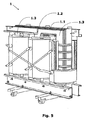
図1は、本発明の教示に従った絶縁システムにより構成される水中用乾式変換器の平面図を示す。 FIG. 1 shows a plan view of an underwater dry transducer constructed with an insulation system in accordance with the teachings of the present invention.
上記の分配変換器は、コア柱又はコア脚1.2、1.3の周りに同心円状に組み立てられた、少なくとも一つの高電圧巻線3及び少なくとも一つの低電圧巻線2を備える。 The distribution converter comprises at least one high-voltage winding 3 and at least one low-voltage winding 2 assembled concentrically around a core column or core leg 1.2, 1.3.
図1は、例えば三相のコア、三つの低電圧巻線2及び三つの高電圧巻線3により形成される三相変換器を示す。
FIG. 1 shows a three-phase converter formed, for example, by a three-phase core, three
三相変換器の場合、図1、4〜7に基づき、上記のコアは、上側コア及び下側コア部分1.1により形成され、コア中心柱1.2及びコアサイド柱1.3により形成されることに留意すべきである。この三相変換器の実施形態は、ここに提案される発明が適用される好ましい実施形態であることに言及すべきである。 In the case of a three-phase converter, based on FIGS. 1, 4 to 7, the core is formed by the upper core and the lower core portion 1.1 and is formed by the core center column 1.2 and the core side column 1.3. It should be noted that. It should be noted that this three-phase converter embodiment is a preferred embodiment to which the invention proposed herein is applied.
また、内側巻線と呼ばれる低電圧巻線2と、外側巻線と呼ばれる高電圧巻線3は、二つのコア柱1.2と1.3の間のスペースとして定義されるコア窓20の存在を表すこともできる固体物質から電気的に絶縁される。そうではなく、コア窓20は、コア脚1.2、1.3の高さにおいて、中心柱又はコア脚1.2と、サイド柱又はコア脚1.3により形成されるスペースと定義される、ということができる。
Also, the low voltage winding 2 called the inner winding and the high voltage winding 3 called the outer winding are present in the presence of the
各コア脚1.2及び1.3には、内側コイル2及び外側コイル3により形成されるコイルのセットが組み立てられる。
A set of coils formed by the
本発明の非常に革新的な特徴は、提案される分配変換器が少なくとも上記の変換器のコア窓20に組み立てられた少なくとも一つの電気絶縁シート4を、電気絶縁シート4の組み立てをその変換器の長手方向300に定めるように備えるという事実に関する。
A very innovative feature of the present invention is that the proposed distribution converter comprises at least one
図1、6及び7は、本発明の教示に従った、上記の電気絶縁シート4の組み立てをさらに詳細に示す。さらに図2は、本発明の目的に従った、低電圧巻線2及び高電圧巻線3の通路のチャネル15を対象とする絶縁シート4の適切な構造面について説明する。
1, 6 and 7 show in more detail the assembly of the
かかるチャネル15は、絶縁シート4の構造を通り抜ける低電圧巻線2及び高電圧巻線3の通路を与える。
Such a
他方、図1、4に示されるように、電気絶縁シート4の組み立てにより、変換器の長手の軸300に対して向かいあう方向に等しく分けられる、変換器の第1のサイド100及び変換器の第2のサイド200が定められるということができる。そして、電気絶縁壁4は、変換器が浸水したときに、変換器の第1のサイド100を変換器の第2のサイド200から電気的に絶縁するように構成される。図7は、上記の機械が浸水したときの、電気絶縁シート4を強調表示する三相の水中用乾式変換器の第2の透視図を示す。電気絶縁シート4は、巻線又はコイルによって占有されていないコア窓20のスペースを包囲するということができる。
On the other hand, as shown in FIGS. 1 and 4, by assembling the electrical insulating
他方、絶縁シート4は、分配変換器の左サイドと右サイドの間の固形の隔壁で構成されるということができる。図1は、ここに提案される目的、特に乾式変換器を数万kVAまでの電力用に製造できるように設計する目的に係るさらなる革新的な特徴を示す。かかる特徴は、低電圧巻線2と高電圧巻線3の間、上記の巻線とコア柱1.2、1.3の間及び巻線2、3の内部に存在するスペースとして定義される冷却チャネル25の使用を目的とする。
On the other hand, it can be said that the insulating
水中用変換器における先行技術と比較した、本発明に係る変換器によって提案される効果は、保護用の小個室を必要とすることなく、浸水したときに500kVAから2MVAまでの割合の電力下で機械が動作することを可能とする、上記の冷却チャネル25の使用を含む。
Compared to the prior art in underwater converters, the proposed effect of the converter according to the present invention is that under submerged power rates from 500 kVA to 2 MVA when submerged without the need for a protective private compartment. Including the use of the cooling
また、想定される目的が達成されるように、電気絶縁壁4に関して、これは樹脂及びガラスファイバーで作られた絶縁物質により構成されることが好ましい。いずれにしても、類似した特性をもつ他の物質を、その機能を損なうことなく上記のシート4の構成に用いることもできる。
Also, with respect to the electrically insulating
本発明の教示に従って、電気絶縁壁4は、シリコーン材料を用いる低電圧巻線2及び高電圧巻線3に対して遮断されることが好ましいことに言及すべきである。しかしながら、提案されるように、絶縁壁4上で巻線を遮断するために他の方法を用いることができる。
It should be noted that in accordance with the teachings of the present invention, the electrically insulating
また、電気絶縁壁4は、厚さ4mmのシートにより形成されることが極めて好ましい。
The electric insulating
電気絶縁シート4は、三相変換器及び単相変換器の両方に適用されることを強調すべきである。他方、既に述べたように、本発明は、三相分配変換器向けとすることが好ましい。他方、水中用乾式分配変換器は、変換器が浸水したときに、液体の通過及び導電性のらせんの形成を遮るように構成された少なくとも一つの電気絶縁シート4を備える形で、コア柱1.2、1.3の周りに同心円状に組み立てられた少なくとも一つの高電圧巻線3及び少なくとも一つの低電圧巻線2を備えるということができる。
It should be emphasized that the
この場合、上記の絶縁シート4は、変換器が浸水したときに、コア窓20を介して導電性のらせんが変換器の第1のサイドから変換器の第2のサイドへ循環することを妨げる。そして変換器の第1のサイドと変換器の第2のサイドは、その変換器の長手の軸300に対して向かいあう方向に等しく分けられる。
In this case, the insulating
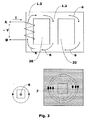
図3は、本発明で提案されるソリューションが適用されない場合、つまり電気絶縁シート4が用いられない場合のコアの周りの電流7の循環を示す。
FIG. 3 shows the circulation of the current 7 around the core when the solution proposed in the present invention is not applied, ie when the
同じ図3は、その巻線が交流電源と接続されたときにその変換器のコアに発生する磁気の流れ6を示す。
The same FIG. 3 shows the
かかる磁気の流れ6は、変換器のコア1.1/1.2/1.3を循環し、コアの周りのらせんに電圧を誘起する。
Such a
らせんの形成のためには、コアの周りに導電体物質が存在している必要がある。他方、残留物をもつ汚れた水は導電体である。このように、ここに提案される目的に従った、電気絶縁シート4の設置は、コアの周りの水により形成されるらせんを遮断する。
In order to form a helix, a conductive material needs to be present around the core. On the other hand, dirty water with residue is a conductor. Thus, the installation of the
シート4により形成される、かかる絶縁システムは、水によるらせんの形成を妨げるのに不可欠であり、また、その遮断により、そのコア1.1/1.2/1.3の周りの寄生電流7の循環と、変換器の電力の減少を促進する電力の損失を回避することができる。
Such an insulation system formed by the
従って、既に述べたように、本発明の目的に従って、電気絶縁シート4の使用により、変換器は、今日の最新技術分野で利用可能な変換器よりきわめて高い電力において動作することができる。
Thus, as already mentioned, according to the object of the present invention, the use of the electrical insulating
さらに、提案されたように、電力変換器の配置は、オイル内の水中用変換器と比較して、火災の場合に自動消化するほかに爆発せず、それにより、よりシンプルでより経済的に施工された地下室に設置することができ、人的危険性と材料費を最小化することができるという効果を有する。 In addition, as suggested, the power converter arrangement does not explode in addition to automatic digestion in the event of a fire compared to the underwater converter in oil, which makes it simpler and more economical It can be installed in the installed basement, and has the effect of minimizing human risk and material costs.
本発明に係る分配変換器のさらなる効果は、運搬中又は変換器の動作中に漏れが発生すると例えば地下水等の環境を汚染する絶縁オイルを使用しないという事実に関する。そのため、本発明でここに提案される水中用変換器の設置用の地下室は、漏れ又は爆発の場合に備えてオイルの封じ込め用のシステムを必要とせず、より経済的且つよりシンプルな方法で施工することができる。 A further advantage of the distribution converter according to the invention relates to the fact that no insulating oil is used which pollutes the environment, for example groundwater, if a leak occurs during transport or operation of the converter. Therefore, the basement for installing the underwater transducer proposed here in the present invention does not require an oil containment system in case of leakage or explosion, and is constructed in a more economical and simpler manner. can do.
好適な実施形態の例を説明したが、本発明の範囲が、添付の特許請求の範囲の内容によってのみ限定される他の可能な変形例、そこに含まれる潜在的な均等物を包含することが理解されるべきである。 While examples of preferred embodiments have been described, the scope of the present invention encompasses other possible variations limited only by the content of the appended claims and the potential equivalents contained therein. Should be understood.
Claims (9)
コア柱(1.2、1.3)の周りに同心円状に組み立てられた少なくとも一つの高電圧巻線(3)及び少なくとも一つの低電圧巻線(2)と、
二つの前記コア柱(1.2、1.3)の間のスペースとして定められるコア窓(20)とを備え、
前記低電圧巻線(2)及び前記高電圧巻線(3)は固体絶縁され、
前記変換器は、少なくとも前記変換器のコア窓(20)に組み立てられた少なくとも一つの、固形の電気絶縁シート(4)を備えることと、前記電気絶縁シート(4)の前記組み立てを前記変換器の長手方向(300)と平行になるように定めることと、前記電気絶縁シート(4)は、前記変換器が浸水したときに、前記コア窓(20)の全ての面に渡って、変換器の第1のサイド(100)を変換器の第2のサイド(200)から電気的に絶縁するように構成されることと、を特徴とする、水中用乾式分配変換器。 A converter,
At least one high voltage winding (3) and at least one low voltage winding (2) assembled concentrically around the core pillar (1.2, 1.3);
A core window (20) defined as a space between the two core pillars (1.2, 1.3),
The low voltage winding (2) and the high voltage winding (3) are solid- insulated,
It said transducer includes at least one assembled at least the transducer core window (20), and Rukoto with a solid electrical insulation sheet (4), the conversion of the assembly of the electrical insulating sheet (4) and it is defined to be parallel to the longitudinal direction (300) of the vessel, the electrically insulating sheet (4), when the transducer is submerged, over all surfaces of said core window (20), conversion A submerged dry distribution converter, characterized in that it is configured to electrically insulate the first side (100) of the vessel from the second side (200) of the converter.
コア柱(1.2、1.3)の周りに同心円状に組み立てられた少なくとも一つの高電圧巻線(3)及び少なくとも一つの低電圧巻線(2)と、
二つの前記コア柱(1.2、1.3)の間のスペースとして定められるコア窓(20)と、を備え、
前記低電圧巻線(2)及び前記高電圧巻線(3)は固体絶縁され、
前記変換器は、少なくとも前記変換器のコア窓(20)に組み立てられた少なくとも一つの電気絶縁シート(4)であって、前記変換器が浸水したときに、変換器の第1のサイド(100)から変換器の第2のサイド(200)への液体の通過及び導電性のらせんの形成を完全に遮るように構成された電気絶縁シート(4)を備えることと、前記電気絶縁シート(4)の前記組み立てを前記変換器の長手方向(300)と平行になるように定めることと、前記変換器の第1のサイド(100)及び前記変換器の第2のサイド(200)は、前記変換器の長手の軸(300)に対して向かい合う方向に等しく分けられることと、を特徴とする、水中用乾式分配変換器。 A converter,
At least one high voltage winding (3) and at least one low voltage winding (2) assembled concentrically around the core pillar (1.2, 1.3) ;
A core window (20) defined as a space between the two core pillars (1.2, 1.3) ,
The low voltage winding (2) and the high voltage winding (3) are solid-insulated,
The converter is at least one electrically insulating sheet (4) assembled to at least the core window (20) of the converter, and when the converter is submerged, the first side (100) of the converter and Rukoto with the configured electrical insulation sheet (4) so as to block completely the passage and formation of the conductive helix of liquid into the second side of the transducer (200) from), the electric insulating sheet Defining the assembly of (4) to be parallel to the longitudinal direction (300) of the transducer, and the first side (100) of the transducer and the second side (200) of the transducer are A submerged dry distribution converter, characterized in that it is equally divided in a direction facing the longitudinal axis (300) of the converter.
Applications Claiming Priority (3)
| Application Number | Priority Date | Filing Date | Title |
|---|---|---|---|
| BRPI0903695-4A BRPI0903695A2 (en) | 2009-05-19 | 2009-05-19 | submersibly dry distribution transformer |
| BRPI0903695-4 | 2009-05-19 | ||
| PCT/BR2010/000163 WO2010132968A1 (en) | 2009-05-19 | 2010-05-18 | Submersible dry distribution transformer |
Publications (3)
| Publication Number | Publication Date |
|---|---|
| JP2012527745A JP2012527745A (en) | 2012-11-08 |
| JP2012527745A5 JP2012527745A5 (en) | 2013-06-20 |
| JP5559314B2 true JP5559314B2 (en) | 2014-07-23 |
Family
ID=42283150
Family Applications (1)
| Application Number | Title | Priority Date | Filing Date |
|---|---|---|---|
| JP2012511105A Expired - Fee Related JP5559314B2 (en) | 2009-05-19 | 2010-05-18 | Underwater dry distribution converter |
Country Status (7)
| Country | Link |
|---|---|
| US (1) | US8614614B2 (en) |
| EP (1) | EP2433289B1 (en) |
| JP (1) | JP5559314B2 (en) |
| CN (1) | CN102460616B (en) |
| BR (1) | BRPI0903695A2 (en) |
| ES (1) | ES2432473T3 (en) |
| WO (1) | WO2010132968A1 (en) |
Families Citing this family (15)
| Publication number | Priority date | Publication date | Assignee | Title |
|---|---|---|---|---|
| BRPI1101495B1 (en) | 2011-04-15 | 2020-09-24 | Siemens Aktiengesellschaft | Three-phase or single-phase dry distribution transformer and electrical isolation method for a tap panel of a three-phase or single-phase dry distribution transformer |
| CN103988268A (en) * | 2011-10-28 | 2014-08-13 | Abb技术有限公司 | Integral mold for a transformer having a non-linear core |
| CN104871265A (en) * | 2012-12-17 | 2015-08-26 | Abb技术有限公司 | A transformer high voltage coil assembly |
| US9070503B2 (en) * | 2013-09-25 | 2015-06-30 | Shun-Fu Technology Corp. | Dry type economizer |
| WO2016137971A1 (en) * | 2015-02-23 | 2016-09-01 | Abb Technology Ag | Auto-balancing transformers |
| FR3054365B1 (en) * | 2016-07-22 | 2018-08-31 | Alstom Transp Tech | ELECTRICAL TRANSFORMER COMPRISING AN INSULATING MATERIAL, AND METHOD FOR MANUFACTURING SUCH TRANSFORMER |
| DE102017220781B4 (en) | 2017-11-21 | 2019-09-26 | Siemens Aktiengesellschaft | Method for producing spacers for a winding unit and winding unit |
| US11017938B2 (en) | 2018-03-08 | 2021-05-25 | Siemens Energy Global GmbH & Co. KG | Methods, apparatus and systems for dry-type transformers |
| CA3097935C (en) | 2018-04-23 | 2022-08-23 | Siemens Aktiengesellschaft | Transformer cores and assembly methods thereof for high efficiency and high anti-corrosion performance |
| US11049647B2 (en) | 2018-04-23 | 2021-06-29 | Siemens Energy Global GmbH & Co. KG | Molded tap changer assemblies and methods for dry-type transformers |
| US11315727B2 (en) | 2018-05-16 | 2022-04-26 | Arteche North America S.A. de C.V. | Explosion-proof inductive voltage transformer |
| CA3102648C (en) | 2018-06-07 | 2023-10-31 | Siemens Aktiengesellschaft | Shielded coil assemblies and methods for dry-type transformers |
| CA3102644C (en) | 2018-06-07 | 2021-08-17 | Siemens Aktiengesellschaft | Core sealing assemblies, core-coil assemblies, and sealing methods |
| EP3916742A1 (en) * | 2020-05-27 | 2021-12-01 | ABB Power Grids Switzerland AG | Transformer insulation modification |
| KR102603476B1 (en) * | 2023-07-05 | 2023-11-17 | 산일전기 주식회사 | power lines and frame integrated mold transformer |
Family Cites Families (14)
| Publication number | Priority date | Publication date | Assignee | Title |
|---|---|---|---|---|
| US2403072A (en) * | 1943-06-30 | 1946-07-02 | Westinghouse Electric Corp | Electrical induction apparatus |
| US2855576A (en) * | 1954-09-27 | 1958-10-07 | Fed Pacific Electric Co | Transformers |
| US3037177A (en) * | 1957-12-12 | 1962-05-29 | Gen Electric | Stationary induction apparatus |
| US3302149A (en) * | 1964-09-30 | 1967-01-31 | Westinghouse Electric Corp | Electrical insulating structure |
| GB1087594A (en) * | 1964-10-23 | 1967-10-18 | Westinghouse Electric Corp | Electrical apparatus |
| BE756562A (en) * | 1969-09-24 | 1971-03-24 | Westinghouse Electric Corp | INDUCTION ELECTRICAL APPLIANCES |
| US3783426A (en) * | 1973-01-09 | 1974-01-01 | Westinghouse Electric Corp | Electrical inductive apparatus having rigid foam supporting members and methods of providing same |
| US4095205A (en) | 1977-07-28 | 1978-06-13 | Westinghouse Electric Corp. | Transformer with improved insulator |
| US4173747A (en) * | 1978-06-08 | 1979-11-06 | Westinghouse Electric Corp. | Insulation structures for electrical inductive apparatus |
| JPS5936895Y2 (en) * | 1979-05-10 | 1984-10-12 | 株式会社高岳製作所 | Transformer for underground installation |
| JPS60105656U (en) * | 1983-12-21 | 1985-07-18 | 株式会社東芝 | Underground-installed electrical equipment |
| JP3305421B2 (en) * | 1993-05-21 | 2002-07-22 | 三菱電機株式会社 | Synthetic resin mold type transformer and method of forming the same |
| JPH08222458A (en) * | 1995-02-17 | 1996-08-30 | Toyo Electric Mfg Co Ltd | Vibration and noise control method of reactor or transformer |
| US5656984A (en) * | 1995-04-06 | 1997-08-12 | Centre D'innovation Sur Le Transport D'energie Du Quebec | Solid insulation transformer |
-
2009
- 2009-05-19 BR BRPI0903695-4A patent/BRPI0903695A2/en not_active Application Discontinuation
-
2010
- 2010-05-18 EP EP10721281.3A patent/EP2433289B1/en active Active
- 2010-05-18 WO PCT/BR2010/000163 patent/WO2010132968A1/en active Application Filing
- 2010-05-18 CN CN201080033708.7A patent/CN102460616B/en active Active
- 2010-05-18 US US13/321,361 patent/US8614614B2/en active Active
- 2010-05-18 JP JP2012511105A patent/JP5559314B2/en not_active Expired - Fee Related
- 2010-05-18 ES ES10721281T patent/ES2432473T3/en active Active
Also Published As
| Publication number | Publication date |
|---|---|
| EP2433289B1 (en) | 2013-07-24 |
| BRPI0903695A2 (en) | 2011-02-15 |
| CN102460616B (en) | 2015-05-06 |
| US8614614B2 (en) | 2013-12-24 |
| US20120126923A1 (en) | 2012-05-24 |
| EP2433289A1 (en) | 2012-03-28 |
| ES2432473T3 (en) | 2013-12-03 |
| CN102460616A (en) | 2012-05-16 |
| JP2012527745A (en) | 2012-11-08 |
| WO2010132968A1 (en) | 2010-11-25 |
Similar Documents
| Publication | Publication Date | Title |
|---|---|---|
| JP5559314B2 (en) | Underwater dry distribution converter | |
| Vijayaraghavan et al. | Practical grounding, bonding, shielding and surge protection | |
| BG63442B1 (en) | Dc transformer/converter | |
| CA2827730C (en) | Dry-type network transformer | |
| JP2014504806A (en) | Dry distribution transformer | |
| CN101213624B (en) | A high voltage insulation system and a method of manufacturing same | |
| EP3791413B1 (en) | Shielded coil assemblies and methods for dry-type transformers | |
| US11145455B2 (en) | Transformer and an associated method thereof | |
| EP2528071B1 (en) | High voltage arrangement comprising an insulating structure | |
| TW201535437A (en) | Static Apparatus | |
| WO2001008175A1 (en) | Distribution transformer | |
| Navarro et al. | Submersible dry-type transformer | |
| KR101192609B1 (en) | Mof for reliability improvement | |
| Lee et al. | Solid insulation distribution transformer | |
| US11972893B2 (en) | Shielded coil assemblies and methods for dry-type transformers | |
| SE512105C2 (en) | switchgear Station | |
| US9601260B2 (en) | Method of manufacturing an electromagnetic induction device and an electromagnetic induction device | |
| Kharezy | High Voltage Dc-Biased Oil Type Medium Frequency Transformer; A Green Solution for Series Dc Wind Park Concept | |
| Zhao | Sheath Bonding Equipment for AC Transmission Cable Systems | |
| Selvaraj et al. | A case study on basic requirements for the design of high voltage bushings | |
| Yi et al. | SOLID INSULATION DISTRIBUTION TRANSFORMER | |
| Pendergrass et al. | Cast Coil Transformers: An Alternative to Conventional Dry Type Transformers | |
| SE508556C2 (en) | Power transformer and reactor with windings with conductors | |
| MXPA98009865A (en) | Transformer / reac |
Legal Events
| Date | Code | Title | Description |
|---|---|---|---|
| A521 | Request for written amendment filed |
Free format text: JAPANESE INTERMEDIATE CODE: A523 Effective date: 20130424 |
|
| A621 | Written request for application examination |
Free format text: JAPANESE INTERMEDIATE CODE: A621 Effective date: 20130424 |
|
| A131 | Notification of reasons for refusal |
Free format text: JAPANESE INTERMEDIATE CODE: A131 Effective date: 20140114 |
|
| A521 | Request for written amendment filed |
Free format text: JAPANESE INTERMEDIATE CODE: A523 Effective date: 20140411 |
|
| TRDD | Decision of grant or rejection written | ||
| A01 | Written decision to grant a patent or to grant a registration (utility model) |
Free format text: JAPANESE INTERMEDIATE CODE: A01 Effective date: 20140513 |
|
| A61 | First payment of annual fees (during grant procedure) |
Free format text: JAPANESE INTERMEDIATE CODE: A61 Effective date: 20140605 |
|
| R150 | Certificate of patent or registration of utility model |
Ref document number: 5559314 Country of ref document: JP Free format text: JAPANESE INTERMEDIATE CODE: R150 |
|
| S111 | Request for change of ownership or part of ownership |
Free format text: JAPANESE INTERMEDIATE CODE: R313113 |
|
| R350 | Written notification of registration of transfer |
Free format text: JAPANESE INTERMEDIATE CODE: R350 |
|
| R250 | Receipt of annual fees |
Free format text: JAPANESE INTERMEDIATE CODE: R250 |
|
| R250 | Receipt of annual fees |
Free format text: JAPANESE INTERMEDIATE CODE: R250 |
|
| R250 | Receipt of annual fees |
Free format text: JAPANESE INTERMEDIATE CODE: R250 |
|
| R250 | Receipt of annual fees |
Free format text: JAPANESE INTERMEDIATE CODE: R250 |
|
| R250 | Receipt of annual fees |
Free format text: JAPANESE INTERMEDIATE CODE: R250 |
|
| R250 | Receipt of annual fees |
Free format text: JAPANESE INTERMEDIATE CODE: R250 |
|
| S111 | Request for change of ownership or part of ownership |
Free format text: JAPANESE INTERMEDIATE CODE: R313113 |
|
| S531 | Written request for registration of change of domicile |
Free format text: JAPANESE INTERMEDIATE CODE: R313531 |
|
| R350 | Written notification of registration of transfer |
Free format text: JAPANESE INTERMEDIATE CODE: R350 |
|
| LAPS | Cancellation because of no payment of annual fees |