EP2433289B1 - Submersible dry distribution transformer - Google Patents
Submersible dry distribution transformer Download PDFInfo
- Publication number
- EP2433289B1 EP2433289B1 EP10721281.3A EP10721281A EP2433289B1 EP 2433289 B1 EP2433289 B1 EP 2433289B1 EP 10721281 A EP10721281 A EP 10721281A EP 2433289 B1 EP2433289 B1 EP 2433289B1
- Authority
- EP
- European Patent Office
- Prior art keywords
- transformer
- core
- electrical insulation
- windings
- insulation sheet
- Prior art date
- Legal status (The legal status is an assumption and is not a legal conclusion. Google has not performed a legal analysis and makes no representation as to the accuracy of the status listed.)
- Active
Links
- 238000009826 distribution Methods 0.000 title claims description 23
- 238000004804 winding Methods 0.000 claims description 55
- 238000010292 electrical insulation Methods 0.000 claims description 30
- XLYOFNOQVPJJNP-UHFFFAOYSA-N water Substances O XLYOFNOQVPJJNP-UHFFFAOYSA-N 0.000 claims description 13
- 239000000463 material Substances 0.000 claims description 12
- 239000007787 solid Substances 0.000 claims description 11
- 238000001816 cooling Methods 0.000 claims description 10
- 239000007788 liquid Substances 0.000 claims description 9
- 239000011810 insulating material Substances 0.000 claims description 6
- 230000015572 biosynthetic process Effects 0.000 claims description 5
- 239000011347 resin Substances 0.000 claims description 4
- 229920005989 resin Polymers 0.000 claims description 4
- 239000003365 glass fiber Substances 0.000 claims description 2
- 229920001296 polysiloxane Polymers 0.000 claims description 2
- 239000011343 solid material Substances 0.000 claims description 2
- 239000003921 oil Substances 0.000 description 23
- 238000009413 insulation Methods 0.000 description 21
- 238000009434 installation Methods 0.000 description 11
- 239000004020 conductor Substances 0.000 description 5
- 238000004880 explosion Methods 0.000 description 4
- 239000002245 particle Substances 0.000 description 4
- 230000008901 benefit Effects 0.000 description 3
- 230000009467 reduction Effects 0.000 description 3
- 239000000725 suspension Substances 0.000 description 3
- 230000005540 biological transmission Effects 0.000 description 2
- 230000008859 change Effects 0.000 description 2
- 238000011109 contamination Methods 0.000 description 2
- 238000012423 maintenance Methods 0.000 description 2
- 238000004519 manufacturing process Methods 0.000 description 2
- 239000002184 metal Substances 0.000 description 2
- 229910052751 metal Inorganic materials 0.000 description 2
- 238000000034 method Methods 0.000 description 2
- 239000000126 substance Substances 0.000 description 2
- 230000009466 transformation Effects 0.000 description 2
- XEEYBQQBJWHFJM-UHFFFAOYSA-N Iron Chemical group [Fe] XEEYBQQBJWHFJM-UHFFFAOYSA-N 0.000 description 1
- FAPWRFPIFSIZLT-UHFFFAOYSA-M Sodium chloride Chemical compound [Na+].[Cl-] FAPWRFPIFSIZLT-UHFFFAOYSA-M 0.000 description 1
- 230000009471 action Effects 0.000 description 1
- 238000003915 air pollution Methods 0.000 description 1
- 230000015556 catabolic process Effects 0.000 description 1
- 238000004140 cleaning Methods 0.000 description 1
- 230000005494 condensation Effects 0.000 description 1
- 238000009833 condensation Methods 0.000 description 1
- 238000010276 construction Methods 0.000 description 1
- 238000005260 corrosion Methods 0.000 description 1
- 230000007797 corrosion Effects 0.000 description 1
- 238000006731 degradation reaction Methods 0.000 description 1
- 239000000428 dust Substances 0.000 description 1
- 230000000694 effects Effects 0.000 description 1
- 230000005684 electric field Effects 0.000 description 1
- 230000007613 environmental effect Effects 0.000 description 1
- 239000003344 environmental pollutant Substances 0.000 description 1
- 238000007654 immersion Methods 0.000 description 1
- 230000001771 impaired effect Effects 0.000 description 1
- 238000007689 inspection Methods 0.000 description 1
- 239000000203 mixture Substances 0.000 description 1
- 238000010422 painting Methods 0.000 description 1
- 244000045947 parasite Species 0.000 description 1
- 231100000719 pollutant Toxicity 0.000 description 1
- -1 polyethylene terephthalate Polymers 0.000 description 1
- 229920000139 polyethylene terephthalate Polymers 0.000 description 1
- 239000005020 polyethylene terephthalate Substances 0.000 description 1
- 230000008569 process Effects 0.000 description 1
- 230000001681 protective effect Effects 0.000 description 1
- 238000000926 separation method Methods 0.000 description 1
- 239000011780 sodium chloride Substances 0.000 description 1
- 239000002689 soil Substances 0.000 description 1
- 238000012795 verification Methods 0.000 description 1
Images


Classifications
-
- H—ELECTRICITY
- H01—ELECTRIC ELEMENTS
- H01F—MAGNETS; INDUCTANCES; TRANSFORMERS; SELECTION OF MATERIALS FOR THEIR MAGNETIC PROPERTIES
- H01F27/00—Details of transformers or inductances, in general
- H01F27/28—Coils; Windings; Conductive connections
- H01F27/32—Insulating of coils, windings, or parts thereof
- H01F27/324—Insulation between coil and core, between different winding sections, around the coil; Other insulation structures
Definitions
- the present invention refers to a single-phase or three-phase distribution electric transformer, of solid insulation; particularly designed for use in underground or submerse distribution installation or internal or external installation.
- transformers are used in the distribution of electric power to enable the transformation of electric power into currents and voltages suitable for transportation from the generation sites to the consumption regions.
- Transmission of electric power is performed under high voltage, up to near the consumption sites where, also by means of transformers, it is reduced to values suitable for the users' equipments.
- Such reduction of the voltage level is performed in several stages, by using transformers which are located close to the centers of power consumption.
- the physical installation of these transformers can be aerial, fastened to poles, or in the ground in internal or external installation or underground installation.
- the distribution transformers for underground networks have their own characteristics, which, for instance in Brazil, are defined by ABNT Standard NBR 9369 Underground Transformers Electric and Mechanic Characteristics - Standardization.
- Other international standards for distribution transformers for underground networks are, for instance, "ANSI C57.12.24-2000, Standard for Transformer-Underground-Type Three-Phase Distribution Transformers, 2500 kVA and Smaller; High Voltage, 34 500 GrdY/19 920 Volts and Below; Low Voltage, 480 Volts and Below-Requirements". Transformers installed in the underground network shall be submersible.
- Transformers are classified according to the constructive type into dry transformers and transformers immersed in insulating liquid.
- Submersible transformers are, in their majority, immersed in insulating liquid, which we will define as oil regardless of its chemical composition.
- the submersible transformers covered by Brazil's standard have a power range at the rate of 200 kVA to 2500 kVA.
- a transformer basically comprises high voltage windings, low voltage windings, iron core for circulation of the magnetic flow, connections among the windings and connection terminals, all of these components lodged inside a metal tank and submerged in oil. Bushings are used to make the link, through the tank, of the internal components to the external connection terminals.
- the transformation relation of the transformer is given by the relation of spirals among the windings.
- the spiral is formed by conductive material around the core, surrounding its circumference.
- the materials forming the spiral around the core are the winding conductors, the insulating materials of the windings and the insulating oil.
- the transformers in insulating liquid have the tank, which contains the active part of the transformer and the insulating oil.
- the oil acts as an electric insulating element between the parts under tension of the transformer and the tank together with the other materials that get impregnated with oil.
- the oil also acts as a cooling element, transmitting and transporting the heat produced in the windings and the core, to the cooling surfaces of the tank and of the radiators.
- insulating materials are used with the suitable spacing, thicknesses and shapes and compatible production process.
- the way of execution and the type of materials used in the parts under tension depend on the intensity of the electric field foreseen in such points which shall be insulated.
- the insulating oil used for its chemical condition and although there are several types available of it, is pollutant, to a higher or lower extent, and shall be properly treated so as to not penetrate the soil nor pollute the water table.
- transformers in oil must have safety devices, according to the standards, which can decrease the risks, but not eliminate them.
- This type of transformer needs ongoing maintenance, requiring regular inspection, to verify the level of oil and its current condition.
- evidencing a reduction in the oil level may indicate the occurrence of leakage.
- Such reduction in the oil level beyond allowable levels may impair electrical insulation and, consequently, the insulation of the transformer.
- Any change to the oil characteristics apart from the foreseen ones may indicate the oil degradation, contamination, the admission of humidity or deviation in the operation of the transformer, and may impair its activity.
- Transformers submersible in oil shall be installed in underground chambers of special execution, which are costly and have a complex building process, resistant to the transformer explosion and with a system for containment of the transformer's oil.
- Dry distribution transformers described, for instance, by Brazilian Standard “NBR 10295 Dry Power Transformers” or by international standards such as "IEC 600076 Power Transformers - Part 11 Dry-type” or "IEEE C57.12.01 Standard for General Requirements for Dry-Type Distribution and Power Transformers, Including Those with Solid-Cast and/or Resin Encapsulated Windings" are dry transformers to be installed under shelter.
- transformers shall be protected from the direct action of bad weather such as rain or snow, once they have a supportability limit of the electrical insulation to humidity.
- the tolerance level to humidity in dry transformers is defined, for instance, in the previously mentioned Standard IEC, classified in this standard into “Classes” C1, C2 and C3. Installation shall be internal, inside buildings or cubicles.
- the transformer's tolerance to humidity and to the surrounding air pollution is obtained by the transformer's constructive model, the materials used, manufacturing process and electrical distances, which provide the transformer with its characteristics of electrical insulation, in humid or polluted environments.
- the insulation of the windings is formed by solid insulation and air.
- the air characteristics participate in determining the transformer's insulating level.
- the air may contain humidity and solid particles under suspension. Both the humidity and the solid particles under suspension, which can be metallic or not, change the insulating characteristics.
- the current dry power transformers shall be installed in sheltered places. They usually have the high voltage windings, the low voltage windings and the core all separated. This separation among the windings and also between the windings and the core serves to insulate the parts and also acts as cooling.
- the spacing among windings or between the windings and the core will be called cooling channels. Cooling is necessary to dissipate the losses generated in the windings and core and to restrict the temperature to that established in the project and standards according to the thermal class of the insulating materials used.
- the circulation of air through the cooling channels and the surface of the windings and core makes it possible to dissipate the losses of the parts to the surrounding air.
- the capacity of dissipating the losses within a temperature level establishes a limit for the transformer power.
- the materials that form the spiral around the core, surrounding it in its circumference are the winding conductors, the insulating materials of the windings, the environment air and the materials deposited on the surface of the windings.
- the set of materials deposited on the surface of the windings or suspended "In the air can become electrically conductive and spiral can be formed, causing the circulation of currents and losses.
- the air surrounding the windings has also the role of insulation because the external surface of the windings is at a certain potential in relation to the ground.
- the windings are a part alive and, for this reason, shall be installed in compliance with the electrical distances pursuant to the manufacturer's instruction and standards, and they cannot be touched when energized.
- the present invention alms at supplying a dry power transformer for installation in submersible and underground distribution networks.
- the dry transformer of the invention has an electrical insulation system independent on the environment surrounding the transformer, whereas the thermal-cooling system allows the dry power transformer of the invention to be manufactured with a power of up to some tens of thousands KVA.
- the goal of the invention is a dry transformer which is submersible because it has an insulation system that performs the interruption of the spiral around the core formed by immersion water.
- the goals of the present invention are also achieved by supplying a submersible dry distribution transformer, sheet being assembled in the longitudinal direction of the transformer, is configured to block the passage of a liquid, particularly water, and the formation of a conductive spiral, formed by the liquid when the transformer is submerged, from a transformer first side to a transformer second side, these, being equally spaced, and at opposite directions, sides of the sheet in the longitudinal axis of the transformer.
- the transformer has windings with solid insulation and may have grounded shield.
- the core and the metal parts exposed are protected from corrosion by a suitable painting system.
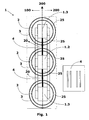
- Figure 1 shows a floor view of the submersible dry transformer, comprised by an insulation system, according to the teachings of the present invention.
- Said distribution transformer comprises at least one high voltage winding 3 and at least one low voltage winding 2 concentrically assembled around a core column, or core legs 1.2, 1.3.
- Figure 1 Illustrates, for instance, a three-phase transformer formed by a three-phase core, by three low voltage windings 2 and three high voltage windings 3.
- the low voltage windings 2, also called internal windings, and the high voltage windings 3, called external windings, are electrically insulated by a solid material, being also possible to note the existence of a core window 20 defined as a space between two core columns 1.2, 1.3. Differently, it is possible to say that the core window 20 is defined as the space formed by the central column, or leg of the core 1.2, and the side columns, or legs of the core 1.3 at the height of the core legs 1.2 e 1.3.
- each core leg 1.2 and 1.3 a set of coils is assembled, which is formed by the inner coils 2 and outer coils 3.
- a very innovative characteristic of the present invention refers to the fact that the proposed distribution transformer comprises at least one electrical insulation sheet 4 assembled on at least a core window 20 of said transformer, so that the assembly of the electrical insulation sheet 4 is defined in the longitudinal direction 300 of the transformer.
- Figures 1 , 6 and 7 show in more details the assembly of said electrical insulation sheet 4, according to the teachings of the present invention.
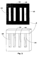
- Figure 2 further illustrates a relevant constructive aspect of the insulation sheet 4, object of the present intention, directed to the channels of passage 16 of the low voltage 2 and high voltage windings 3.
- Such channels 15 allow the passage of the low voltage 2 and high voltage windings 3 through the structure of the insulation sheet 4.
- the assembly of the electrical insulation sheet 4 defines a transformer first side 100 and a transformer second side 200, equally spaced, and at opposite sides, from the longitudinal axis 300 of the transformer, as illustrated by figures 1 e 4 .
- Said electrical insulation wall 4 is then configured so as to electrically insulate the transformer first side 100 from the transformer second side 200 when the transformer is submerged.
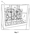
- Figure 7 shows a second perspective view of a three-phase submersible dry transformer, highlighting the electrical insulation sheet 4 when said machine is submerged. It is possible to state that the electrical insulation sheet 4 encompasses the space of the core window 20 which is not occupied by the windings, or coils.
- the insulation sheet 4 consists of a solid dividing wall, between the left side and the right side of the distribution transformer.
- Figure 1 shows an additional innovative characteristic of the object proposed herein, especially designed to allow the dry transformer to be manufactured at powers of up to some tens of thousands KVA.
- Such characteristic is targeted for the use of cooling channels 25, which are defined as spaces that exist between the low voltage and high voltage windings 2,3 , between said windings and the core column 1.2, 1.3 and within the windings 2,3.
- the advantages offered by the transformer of the present invention include the use of said cooling channels 25, which allow the machine to operate under powers at the rate of 500 KVA to 2 MVA, when submerged in water, without the need of a protective Cubicle.
- the electrical insulation wall 4 is preferably comprised by insulating material made of resin and glass fiber, so that the foreseen goals are achieved.
- other materials. with similar characteristics may be employed in the construction of said shoot 4 without impairing hs function.
- the electrical Insulation wall 4 is preferably sealed to the low voltage and high voltage windings 2,3 using silicone material.
- other methods can be used in order to seal the windings on the insulation wall 4. as proposed.
- the electrical insulation wall 4 is formed by a sheet which is 4 mm thick.
- the etectrical insulation sheet 4 is applied both to a three-phase transformer and to a single-phase transformer.
- the present invention is preferably aimed at a three-phase distribution transformer.
- the submersible dry distribution transformer comprises at least one high voltage winding 3 and at least one low voltage winding 2 concentrically assembled around a core column 1.2, 1.3, in a way that said transformer comprises at least one electrical insulation sheet 4 configured to block the passage of a liquid, and the formation of a conductive spiral, when the transformer is submerged.
- said insulation sheet 4 prevents the conductive spiral from circulating from a transformer first side 100 to a transformer second side 200, which are equally spaced, and at opposite directions, from the longitudinal axis 300 of the transformer, trough the core window 20, when the transformer is submerged.
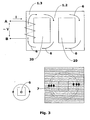
- Figure 3 shows a circulation of electric currents 7 around the core, if the solution proposed in the present invention is not applied; in other words, if the electrical insulation sheet 4 is not used.
- the same figure 3 shows the magnetic flow 6 generated in the core of the transformer when its winding is connected to the alternating current power supply.
- Such insulation system formed by the sheet 4, is indispensable to prevent the spiral formation by water, and upon its interruption, it is possible to also avoid the circulation of parasite electric currents 7 around the core 1.1/1.2/1.3, and losses of electric power which would help reduce the transformer power.
- the use of the electrical insulation sheet 4, according to the object of the present invention allows the transformer to operate at powers quite higher than those available in the state of the art today.
- the arrangement of the power transformer has the advantage - compared to transformers submersible in oil - of not exploding, apart from being self-extinguishable in case of fire, which allows it to be installed in underground chambers of simpler and more economic execution, whereas minimizing personal risks and material costs.
- An additional advantage of the distribution transformer of the present invention refers to the fact that it is free from insulating oils, which could contaminate the environment, such as the water table should leakage occur, during the transportation or during the operation of the transformer.
- the underground chambers for the installation of the submersible transformers proposed in the invention herein can be executed in a more economic and simpler manner, once they do not require a system for oil containment, in case of leakage or explosion.
Description
- The present invention refers to a single-phase or three-phase distribution electric transformer, of solid insulation; particularly designed for use in underground or submerse distribution installation or internal or external installation.
- As known in the state of the art, transformers are used in the distribution of electric power to enable the transformation of electric power into currents and voltages suitable for transportation from the generation sites to the consumption regions. For the transmission of electric power over long distances, which can be tens, hundreds or thousands of kilometers, it is a common practice to raise the voltage by means of transformers, so as to reduce the power losses which occur through the electrical resistance of the electrical cables. Transmission of electric power is performed under high voltage, up to near the consumption sites where, also by means of transformers, it is reduced to values suitable for the users' equipments. Such reduction of the voltage level is performed in several stages, by using transformers which are located close to the centers of power consumption. The physical installation of these transformers can be aerial, fastened to poles, or in the ground in internal or external installation or underground installation.
- In the cities, it is a common practice to perform the distribution of electric power through an underground distribution network. In the distribution of electric power through an underground network, the transformers are installed in underground chambers. The distribution transformers for underground networks have their own characteristics, which, for instance in Brazil, are defined by ABNT Standard NBR 9369 Underground Transformers Electric and Mechanic Characteristics - Standardization. Other international standards for distribution transformers for underground networks are, for instance, "ANSI C57.12.24-2000, Standard for Transformer-Underground-Type Three-Phase Distribution Transformers, 2500 kVA and Smaller; High Voltage, 34 500 GrdY/19 920 Volts and Below; Low Voltage, 480 Volts and Below-Requirements". Transformers installed in the underground network shall be submersible.
- Transformers are classified according to the constructive type into dry transformers and transformers immersed in insulating liquid. Submersible transformers are, in their majority, immersed in insulating liquid, which we will define as oil regardless of its chemical composition. The submersible transformers covered by Brazil's standard have a power range at the rate of 200 kVA to 2500 kVA.
- A transformer basically comprises high voltage windings, low voltage windings, iron core for circulation of the magnetic flow, connections among the windings and connection terminals, all of these components lodged inside a metal tank and submerged in oil. Bushings are used to make the link, through the tank, of the internal components to the external connection terminals.
- Under the laws of physics, the transformation relation of the transformer is given by the relation of spirals among the windings. The spiral is formed by conductive material around the core, surrounding its circumference. In transformers with insulating liquid, the materials forming the spiral around the core are the winding conductors, the insulating materials of the windings and the insulating oil.
- The transformers in insulating liquid have the tank, which contains the active part of the transformer and the insulating oil.. The oil acts as an electric insulating element between the parts under tension of the transformer and the tank together with the other materials that get impregnated with oil. The oil also acts as a cooling element, transmitting and transporting the heat produced in the windings and the core, to the cooling surfaces of the tank and of the radiators.
- To obtain the required insulation among the parts under tension, insulating materials are used with the suitable spacing, thicknesses and shapes and compatible production process. The way of execution and the type of materials used in the parts under tension depend on the intensity of the electric field foreseen in such points which shall be insulated.
- These transformers in oil, although widely used all over the world, present the problems described next.
- The insulating oil used, for its chemical condition and although there are several types available of it, is pollutant, to a higher or lower extent, and shall be properly treated so as to not penetrate the soil nor pollute the water table.
- Once the active part of the transformer is inside a tank, which is full of oil, the internal pressure of the tank can increase as a result of an internal failure, overcharge or also due to an external failure. The raise in the internal pressure may cause the tank to explode preceded or not by fire, with risk of property and human damages. To reduce the risks, transformers in oil must have safety devices, according to the standards, which can decrease the risks, but not eliminate them.
- This type of transformer needs ongoing maintenance, requiring regular inspection, to verify the level of oil and its current condition. Thus, during the verifications, evidencing a reduction in the oil level may indicate the occurrence of leakage. Such reduction in the oil level beyond allowable levels may impair electrical insulation and, consequently, the insulation of the transformer. Any change to the oil characteristics apart from the foreseen ones may indicate the oil degradation, contamination, the admission of humidity or deviation in the operation of the transformer, and may impair its activity.
- Transformers submersible in oil shall be installed in underground chambers of special execution, which are costly and have a complex building process, resistant to the transformer explosion and with a system for containment of the transformer's oil.
- Dry transformers, once they do not have the oil confined inside a tank, suffer neither this risk of explosion nor the risk of environmental contamination by the transformer's oil should leakage or explosion occur.
- Dry distribution transformers, described, for instance, by Brazilian Standard "NBR 10295 Dry Power Transformers" or by international standards such as "IEC 600076 Power Transformers - Part 11 Dry-type" or "IEEE C57.12.01 Standard for General Requirements for Dry-Type Distribution and Power Transformers, Including Those with Solid-Cast and/or Resin Encapsulated Windings" are dry transformers to be installed under shelter.
- These transformers shall be protected from the direct action of bad weather such as rain or snow, once they have a supportability limit of the electrical insulation to humidity. The tolerance level to humidity in dry transformers is defined, for instance, in the previously mentioned Standard IEC, classified in this standard into "Classes" C1, C2 and C3. Installation shall be internal, inside buildings or cubicles.
- The transformer's tolerance to humidity and to the surrounding air pollution is obtained by the transformer's constructive model, the materials used, manufacturing process and electrical distances, which provide the transformer with its characteristics of electrical insulation, in humid or polluted environments.
- The insulation of the windings is formed by solid insulation and air. Thus, the air characteristics participate in determining the transformer's insulating level. The air may contain humidity and solid particles under suspension. Both the humidity and the solid particles under suspension, which can be metallic or not, change the insulating characteristics.
- Depending on the characteristics of the place of installation, the humidity level and the solid particles under suspension, it is possible to choose the class which the dry transformer shall fit, considering the foreseen periods of maintenance and cleaning.
- The current dry power transformers shall be installed in sheltered places. They usually have the high voltage windings, the low voltage windings and the core all separated. This separation among the windings and also between the windings and the core serves to insulate the parts and also acts as cooling. The spacing among windings or between the windings and the core will be called cooling channels. Cooling is necessary to dissipate the losses generated in the windings and core and to restrict the temperature to that established in the project and standards according to the thermal class of the insulating materials used. The circulation of air through the cooling channels and the surface of the windings and core makes it possible to dissipate the losses of the parts to the surrounding air. The capacity of dissipating the losses within a temperature level establishes a limit for the transformer power.
- In dry power transformers, the materials that form the spiral around the core, surrounding it in its circumference, are the winding conductors, the insulating materials of the windings, the environment air and the materials deposited on the surface of the windings. In case of condensation and excessive pollution, such as ore dust or saline environment, the set of materials deposited on the surface of the windings or suspended "In the air can become electrically conductive and spiral can be formed, causing the circulation of currents and losses.
- Additionally, the insulating task of the air gets impaired with the presence of humidity and solid particles. For this reason, the currently available dry power transformers shall be installed in sheltered places, and the tolerance limits to humid or polluted environments shall be established in classes, for instance, pursuant to Standard IEC 60076 - 11.
- In the current dry power transformers, the air surrounding the windings has also the role of insulation because the external surface of the windings is at a certain potential in relation to the ground. The windings are a part alive and, for this reason, shall be installed in compliance with the electrical distances pursuant to the manufacturer's instruction and standards, and they cannot be touched when energized.
- For external installation, there are dry transformers for measuring voltage or current which are completely encapsulated with solid insulation. External air can participate in the insulation or not, depending if it uses a bushing-type terminal or one connectable to a "plug-in" cable. The windings may have external shield that may be grounded or not. The thermal dissipation of these transformers is performed by the external surface itself.
- There are dry power transformers for buried or submersible use, which are completely encapsulated, for little individual powers at the rate of up to 50 kVA with one phase, or 100 kVA with three phases. The thermal dissipation of these transformers is performed by the external surface itself, which limits the transformer power.
- These measuring transformers or power transformers, once they are completely encapsulated in resin, have limitations in dissipating the heat of the losses generated In the windings and in the core, and, for this reason, are manufactured only for short powers. They can have grounded external shield, which occasionally allows them to be installed in external or submerse environments; however, their power is limited to the rate of 100 kVA.
- One prior art in this field is disclosed in
US 4095205 . According to that solution, a transformer with solid insulating structures, those insulating structures includinf polyethylene terephthalate film which is surrounded on each of its major outer surfaces by a layer of paper. - The present invention alms at supplying a dry power transformer for installation in submersible and underground distribution networks. The dry transformer of the invention has an electrical insulation system independent on the environment surrounding the transformer, whereas the thermal-cooling system allows the dry power transformer of the invention to be manufactured with a power of up to some tens of thousands KVA.
- Such goal is achieved by the supply of a submersible dry distribution transformer according to
claim 1. - The goal of the invention is a dry transformer which is submersible because it has an insulation system that performs the interruption of the spiral around the core formed by immersion water.
- Thus, the goals of the present invention are also achieved by supplying a submersible dry distribution transformer, sheet being assembled in the longitudinal direction of the transformer, is configured to block the passage of a liquid, particularly water, and the formation of a conductive spiral, formed by the liquid when the transformer is submerged, from a transformer first side to a transformer second side, these, being equally spaced, and at opposite directions, sides of the sheet in the longitudinal axis of the transformer.
- Additionally, the transformer has windings with solid insulation and may have grounded shield. The core and the metal parts exposed are protected from corrosion by a suitable painting system.
- The present invention will be described next, in more details, based on figures:
-
Figure 1 - represents a floor view of the submersible dry transformer, comprised by an insulation system which performs the interruption of the water spiral around the core, according to the teachings of the present invention (detail of the system for Interrupting the water spiral around the core); -
Figure 2 - represents a view of the electrical insulation sheet, or insulation system, according to the object of the present invention; -
Figure 3 - represents a schematic view of a transformer three-phase core and figures describing the electromagnetic phenomenon of spiral around the core; -
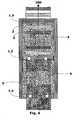
Figure 4 - represents a side view of a three-phase submersible dry transformer, comprised by an Insulation system, or electrical insulation sheet, which performs the interruption of the water spiral around the core. Side sectional view of the half, showing core, high voltage windings, low vol. tage windings and system for interrupting the water spiral around the core; -
Figure 5 - represents a perspective view of a three-phase dry conventional transformer, not submersible; -
Figure 6 - represents a front view of a three-phase submersible dry transformer, highlighting the electrical insulation sheet, according to the object of the present invention; and -
Figure 7 - represents a second perspective view of a three. phase submersible dry transformer, highlighting the electrical insulation sheet when the machine is submerged. -
Figure 1 shows a floor view of the submersible dry transformer, comprised by an insulation system, according to the teachings of the present invention. - Said distribution transformer comprises at least one high voltage winding 3 and at least one low voltage winding 2 concentrically assembled around a core column, or core legs 1.2, 1.3.
-
Figure 1 Illustrates, for instance, a three-phase transformer formed by a three-phase core, by threelow voltage windings 2 and threehigh voltage windings 3. - In the case of the three-phase transformer, It is noted, based on
figures 1 ,4 to 7 that said core is formed by portions of higher core and lower core 1.1, and by the core central columns 1.2 and core side columns 1.3. It is worth mentioning that this three-phase transformer embodiment is the preferred one for the application of the object proposed herein. - The
low voltage windings 2, also called internal windings, and thehigh voltage windings 3, called external windings, are electrically insulated by a solid material, being also possible to note the existence of acore window 20 defined as a space between two core columns 1.2, 1.3. Differently, it is possible to say that thecore window 20 is defined as the space formed by the central column, or leg of the core 1.2, and the side columns, or legs of the core 1.3 at the height of the core legs 1.2 e 1.3. - In each core leg 1.2 and 1.3, a set of coils is assembled, which is formed by the
inner coils 2 andouter coils 3. - A very innovative characteristic of the present invention refers to the fact that the proposed distribution transformer comprises at least one
electrical insulation sheet 4 assembled on at least acore window 20 of said transformer, so that the assembly of theelectrical insulation sheet 4 is defined in thelongitudinal direction 300 of the transformer. -
Figures 1 ,6 and7 show in more details the assembly of saidelectrical insulation sheet 4, according to the teachings of the present invention.Figure 2 further illustrates a relevant constructive aspect of theinsulation sheet 4, object of the present intention, directed to the channels of passage 16 of thelow voltage 2 andhigh voltage windings 3. -
Such channels 15 allow the passage of thelow voltage 2 andhigh voltage windings 3 through the structure of theinsulation sheet 4. - On the other hand, it is possible to state that the assembly of the
electrical insulation sheet 4 defines a transformerfirst side 100 and a transformersecond side 200, equally spaced, and at opposite sides, from thelongitudinal axis 300 of the transformer, as illustrated byfigures 1 .e 4 - Said
electrical insulation wall 4 is then configured so as to electrically insulate the transformerfirst side 100 from the transformersecond side 200 when the transformer is submerged.Figure 7 shows a second perspective view of a three-phase submersible dry transformer, highlighting theelectrical insulation sheet 4 when said machine is submerged. It is possible to state that theelectrical insulation sheet 4 encompasses the space of thecore window 20 which is not occupied by the windings, or coils. - In other words, it is possible to say that the
insulation sheet 4 consists of a solid dividing wall, between the left side and the right side of the distribution transformer. -
Figure 1 shows an additional innovative characteristic of the object proposed herein, especially designed to allow the dry transformer to be manufactured at powers of up to some tens of thousands KVA. Such characteristic is targeted for the use of coolingchannels 25, which are defined as spaces that exist between the low voltage andhigh voltage windings windings - The advantages offered by the transformer of the present invention, compared to the prior arts for submersible transformers, Include the use of said
cooling channels 25, which allow the machine to operate under powers at the rate of 500 KVA to 2 MVA, when submerged in water, without the need of a protective Cubicle. - Also regarding the
electrical insulation wall 4, this is preferably comprised by insulating material made of resin and glass fiber, so that the foreseen goals are achieved. Anyway, other materials. with similar characteristics, may be employed in the construction of saidshoot 4 without impairing hs function. - It is worth mentioning that the
electrical Insulation wall 4, according to the teachings of the present invention, is preferably sealed to the low voltage andhigh voltage windings insulation wall 4. as proposed. - Also quite preferably, the
electrical insulation wall 4 is formed by a sheet which is 4 mm thick. - It is worth highlighting that the
etectrical insulation sheet 4 is applied both to a three-phase transformer and to a single-phase transformer. On the other hand, as already mentioned, the present invention is preferably aimed at a three-phase distribution transformer. - On the other hand, it is possible to say that the submersible dry distribution transformer comprises at least one high voltage winding 3 and at least one low voltage winding 2 concentrically assembled around a core column 1.2, 1.3, in a way that said transformer comprises at least one
electrical insulation sheet 4 configured to block the passage of a liquid, and the formation of a conductive spiral, when the transformer is submerged. - In this case, said
insulation sheet 4 prevents the conductive spiral from circulating from a transformerfirst side 100 to a transformersecond side 200, which are equally spaced, and at opposite directions, from thelongitudinal axis 300 of the transformer, trough thecore window 20, when the transformer is submerged. -
Figure 3 shows a circulation ofelectric currents 7 around the core, if the solution proposed in the present invention is not applied; in other words, if theelectrical insulation sheet 4 is not used. - The same
figure 3 shows themagnetic flow 6 generated in the core of the transformer when its winding is connected to the alternating current power supply. - Such
magnetic flow 6, circulating in the transformer's core 1.1/ 1.2/ 1.3, induces an electrical voltage in the spirals around the core. - For the spiral formation, it is necessary the presence of an electrical conductor material around the core. On the other hand, dirty water and with residues is an electrical conductor. This way, the installation of the
electrical insulation sheet 4, according to the object proposed herein, interrupts the spiral formed by the water which is around the core. - Such insulation system, formed by the
sheet 4, is indispensable to prevent the spiral formation by water, and upon its interruption, it is possible to also avoid the circulation of parasiteelectric currents 7 around the core 1.1/1.2/1.3, and losses of electric power which would help reduce the transformer power. - Therefore, as previously commented, the use of the
electrical insulation sheet 4, according to the object of the present invention, allows the transformer to operate at powers quite higher than those available in the state of the art today. - Furthermore, the arrangement of the power transformer, as proposed, has the advantage - compared to transformers submersible in oil - of not exploding, apart from being self-extinguishable in case of fire, which allows it to be installed in underground chambers of simpler and more economic execution, whereas minimizing personal risks and material costs.
- An additional advantage of the distribution transformer of the present invention refers to the fact that it is free from insulating oils, which could contaminate the environment, such as the water table should leakage occur, during the transportation or during the operation of the transformer. Thus, the underground chambers for the installation of the submersible transformers proposed in the invention herein can be executed in a more economic and simpler manner, once they do not require a system for oil containment, in case of leakage or explosion.
- After describing an example of preferred embodiment, it shall be understood that the scope of the present invention encompasses other possible variations, being limited only by the contents of the attached claims, where the possible equivalents are included.
Claims (9)
- Submersible dry distribution transformer, comprising at least two core columns (1.2, 1.3) aligned in a plane defining the longitudinal direction (300) of the transformer, each column core comprising at least one high voltage winding (3) and at least one low voltage winding (2) concentrically assembled around the core column (1.2, 1.3), the low voltage and high voltage windings (2,3) being electrically isolated by a solid material, at least one core window (20) between the core columns characterized in that said core window is being defined as a space between two core columns (1.2, 1.3), said space extending in the longitudinal direction, at least one solid electrical insulation sheet (4) being assembled on the core window (20) of said transformer, the assembly of the electrical insulation sheet (4) being defined in the longitudinal direction (300) of the transformer.
- Transformer according to claim 1, characterized in that the assembly of the electrical insulation sheet (4) defines a transformer first side (100) and a transformer second side (200) equally spaced, and at opposite Sides of the sheet in, the longitudinal axis (300) of the transformer, the electrical insulation sheet (4) being configured to electrically insulate the transformer first side (100) from the transformer second side (200), trough the core window (20), when the transformer is submerged.
- Transformer according to claim 1, characterized in that it comprises cooling channels (25), which are defined as spaces that exist between the low and high voltage windings (2,3), between said windings and the core column (1.2, 1.3) and within the windings (2,3).
- Transformer according to claim 3, characterized in that the electrical insulation sheet (4) is comprised by an insulating material made of resin and glass fiber.
- Transformer according to claims 1 to 4, characterized in that the electrical insulation sheet (4) is sealed to the low and high voltage windings (2,3) using silicone material.
- Transformer according to claim 1, characterized in that the electrical insulation sheet (4) is formed by a sheet which is 4 mm thick.
- Transformer according to claim 1, characterized in that it is a single-phase or three-phase transformer.
- Submersible dry distribution transformer according to claim 1
characterized in that the electrical insulation sheet (4)
is being configured to block the passage of a liquid, and the, formation of a conductive ligned spiral when the transformer is submerged, from a transformer first side (100) to a transformer second side (200), these being equally spaced, and at opposite sides of the sheet, in the longitudinal direction (300) of the transformer. - Transformer according to claim 8, characterized in that the liquid is water.
Applications Claiming Priority (2)
| Application Number | Priority Date | Filing Date | Title |
|---|---|---|---|
| BRPI0903695-4A BRPI0903695A2 (en) | 2009-05-19 | 2009-05-19 | submersibly dry distribution transformer |
| PCT/BR2010/000163 WO2010132968A1 (en) | 2009-05-19 | 2010-05-18 | Submersible dry distribution transformer |
Publications (2)
| Publication Number | Publication Date |
|---|---|
| EP2433289A1 EP2433289A1 (en) | 2012-03-28 |
| EP2433289B1 true EP2433289B1 (en) | 2013-07-24 |
Family
ID=42283150
Family Applications (1)
| Application Number | Title | Priority Date | Filing Date |
|---|---|---|---|
| EP10721281.3A Active EP2433289B1 (en) | 2009-05-19 | 2010-05-18 | Submersible dry distribution transformer |
Country Status (7)
| Country | Link |
|---|---|
| US (1) | US8614614B2 (en) |
| EP (1) | EP2433289B1 (en) |
| JP (1) | JP5559314B2 (en) |
| CN (1) | CN102460616B (en) |
| BR (1) | BRPI0903695A2 (en) |
| ES (1) | ES2432473T3 (en) |
| WO (1) | WO2010132968A1 (en) |
Cited By (1)
| Publication number | Priority date | Publication date | Assignee | Title |
|---|---|---|---|---|
| WO2019101459A1 (en) | 2017-11-21 | 2019-05-31 | Siemens Aktiengesellschaft | Method for producing spacers for a winding unit and voltage-resistant spacers for cast resin transformers |
Families Citing this family (14)
| Publication number | Priority date | Publication date | Assignee | Title |
|---|---|---|---|---|
| BRPI1101495B1 (en) | 2011-04-15 | 2020-09-24 | Siemens Aktiengesellschaft | Three-phase or single-phase dry distribution transformer and electrical isolation method for a tap panel of a three-phase or single-phase dry distribution transformer |
| CN103988268A (en) * | 2011-10-28 | 2014-08-13 | Abb技术有限公司 | Integral mold for a transformer having a non-linear core |
| CN104871265A (en) * | 2012-12-17 | 2015-08-26 | Abb技术有限公司 | A transformer high voltage coil assembly |
| US9070503B2 (en) * | 2013-09-25 | 2015-06-30 | Shun-Fu Technology Corp. | Dry type economizer |
| WO2016137971A1 (en) * | 2015-02-23 | 2016-09-01 | Abb Technology Ag | Auto-balancing transformers |
| FR3054365B1 (en) * | 2016-07-22 | 2018-08-31 | Alstom Transp Tech | ELECTRICAL TRANSFORMER COMPRISING AN INSULATING MATERIAL, AND METHOD FOR MANUFACTURING SUCH TRANSFORMER |
| US11017938B2 (en) | 2018-03-08 | 2021-05-25 | Siemens Energy Global GmbH & Co. KG | Methods, apparatus and systems for dry-type transformers |
| CA3097935C (en) | 2018-04-23 | 2022-08-23 | Siemens Aktiengesellschaft | Transformer cores and assembly methods thereof for high efficiency and high anti-corrosion performance |
| US11049647B2 (en) | 2018-04-23 | 2021-06-29 | Siemens Energy Global GmbH & Co. KG | Molded tap changer assemblies and methods for dry-type transformers |
| US11315727B2 (en) | 2018-05-16 | 2022-04-26 | Arteche North America S.A. de C.V. | Explosion-proof inductive voltage transformer |
| CA3102648C (en) | 2018-06-07 | 2023-10-31 | Siemens Aktiengesellschaft | Shielded coil assemblies and methods for dry-type transformers |
| CA3102644C (en) | 2018-06-07 | 2021-08-17 | Siemens Aktiengesellschaft | Core sealing assemblies, core-coil assemblies, and sealing methods |
| EP3916742A1 (en) * | 2020-05-27 | 2021-12-01 | ABB Power Grids Switzerland AG | Transformer insulation modification |
| KR102603476B1 (en) * | 2023-07-05 | 2023-11-17 | 산일전기 주식회사 | power lines and frame integrated mold transformer |
Family Cites Families (14)
| Publication number | Priority date | Publication date | Assignee | Title |
|---|---|---|---|---|
| US2403072A (en) * | 1943-06-30 | 1946-07-02 | Westinghouse Electric Corp | Electrical induction apparatus |
| US2855576A (en) * | 1954-09-27 | 1958-10-07 | Fed Pacific Electric Co | Transformers |
| US3037177A (en) * | 1957-12-12 | 1962-05-29 | Gen Electric | Stationary induction apparatus |
| US3302149A (en) * | 1964-09-30 | 1967-01-31 | Westinghouse Electric Corp | Electrical insulating structure |
| GB1087594A (en) * | 1964-10-23 | 1967-10-18 | Westinghouse Electric Corp | Electrical apparatus |
| BE756562A (en) * | 1969-09-24 | 1971-03-24 | Westinghouse Electric Corp | INDUCTION ELECTRICAL APPLIANCES |
| US3783426A (en) * | 1973-01-09 | 1974-01-01 | Westinghouse Electric Corp | Electrical inductive apparatus having rigid foam supporting members and methods of providing same |
| US4095205A (en) | 1977-07-28 | 1978-06-13 | Westinghouse Electric Corp. | Transformer with improved insulator |
| US4173747A (en) * | 1978-06-08 | 1979-11-06 | Westinghouse Electric Corp. | Insulation structures for electrical inductive apparatus |
| JPS5936895Y2 (en) * | 1979-05-10 | 1984-10-12 | 株式会社高岳製作所 | Transformer for underground installation |
| JPS60105656U (en) * | 1983-12-21 | 1985-07-18 | 株式会社東芝 | Underground-installed electrical equipment |
| JP3305421B2 (en) * | 1993-05-21 | 2002-07-22 | 三菱電機株式会社 | Synthetic resin mold type transformer and method of forming the same |
| JPH08222458A (en) * | 1995-02-17 | 1996-08-30 | Toyo Electric Mfg Co Ltd | Vibration and noise control method of reactor or transformer |
| US5656984A (en) * | 1995-04-06 | 1997-08-12 | Centre D'innovation Sur Le Transport D'energie Du Quebec | Solid insulation transformer |
-
2009
- 2009-05-19 BR BRPI0903695-4A patent/BRPI0903695A2/en not_active Application Discontinuation
-
2010
- 2010-05-18 EP EP10721281.3A patent/EP2433289B1/en active Active
- 2010-05-18 WO PCT/BR2010/000163 patent/WO2010132968A1/en active Application Filing
- 2010-05-18 CN CN201080033708.7A patent/CN102460616B/en active Active
- 2010-05-18 US US13/321,361 patent/US8614614B2/en active Active
- 2010-05-18 JP JP2012511105A patent/JP5559314B2/en not_active Expired - Fee Related
- 2010-05-18 ES ES10721281T patent/ES2432473T3/en active Active
Cited By (1)
| Publication number | Priority date | Publication date | Assignee | Title |
|---|---|---|---|---|
| WO2019101459A1 (en) | 2017-11-21 | 2019-05-31 | Siemens Aktiengesellschaft | Method for producing spacers for a winding unit and voltage-resistant spacers for cast resin transformers |
Also Published As
| Publication number | Publication date |
|---|---|
| BRPI0903695A2 (en) | 2011-02-15 |
| CN102460616B (en) | 2015-05-06 |
| US8614614B2 (en) | 2013-12-24 |
| JP5559314B2 (en) | 2014-07-23 |
| US20120126923A1 (en) | 2012-05-24 |
| EP2433289A1 (en) | 2012-03-28 |
| ES2432473T3 (en) | 2013-12-03 |
| CN102460616A (en) | 2012-05-16 |
| JP2012527745A (en) | 2012-11-08 |
| WO2010132968A1 (en) | 2010-11-25 |
Similar Documents
| Publication | Publication Date | Title |
|---|---|---|
| EP2433289B1 (en) | Submersible dry distribution transformer | |
| EP0888628B1 (en) | Transformer/reactor | |
| EP2671234B1 (en) | Dry distribution transformer | |
| EP2169692B1 (en) | High voltage step-up dry power transformer and power supply unit comprising at least one such transformer | |
| US20110310523A1 (en) | Electrical apparatus with electrostatic shield | |
| KR100755888B1 (en) | Waterproofing Terminal of Distribution Transformer | |
| US20220336137A1 (en) | A non-liquid immersed transformer | |
| WO2001008175A1 (en) | Distribution transformer | |
| KR101506886B1 (en) | Discharge energy by electromagnetic fields and electric shock prevention device using coil electrode | |
| EP2528071B1 (en) | High voltage arrangement comprising an insulating structure | |
| US1878094A (en) | Oil-cooled terminal | |
| Navarro et al. | Submersible dry-type transformer | |
| KR101506887B1 (en) | Cylinder electrode type prevention device for discharge energy by electromagnetic fields and electric shock | |
| KR20000016097A (en) | Direct current transformer and reactor | |
| KR101870106B1 (en) | Submersible Type Distribution Transformer | |
| Lee et al. | Solid insulation distribution transformer | |
| CA2311748A1 (en) | Switch gear station | |
| CN113488321A (en) | Dry-type transformer and winding method thereof | |
| JPH0917648A (en) | Stationary induction electric device | |
| MXPA98009865A (en) | Transformer / reac |
Legal Events
| Date | Code | Title | Description |
|---|---|---|---|
| PUAI | Public reference made under article 153(3) epc to a published international application that has entered the european phase |
Free format text: ORIGINAL CODE: 0009012 |
|
| 17P | Request for examination filed |
Effective date: 20111125 |
|
| AK | Designated contracting states |
Kind code of ref document: A1 Designated state(s): AL AT BE BG CH CY CZ DE DK EE ES FI FR GB GR HR HU IE IS IT LI LT LU LV MC MK MT NL NO PL PT RO SE SI SK SM TR |
|
| DAX | Request for extension of the european patent (deleted) | ||
| GRAP | Despatch of communication of intention to grant a patent |
Free format text: ORIGINAL CODE: EPIDOSNIGR1 |
|
| GRAS | Grant fee paid |
Free format text: ORIGINAL CODE: EPIDOSNIGR3 |
|
| GRAA | (expected) grant |
Free format text: ORIGINAL CODE: 0009210 |
|
| AK | Designated contracting states |
Kind code of ref document: B1 Designated state(s): AL AT BE BG CH CY CZ DE DK EE ES FI FR GB GR HR HU IE IS IT LI LT LU LV MC MK MT NL NO PL PT RO SE SI SK SM TR |
|
| REG | Reference to a national code |
Ref country code: GB Ref legal event code: FG4D |
|
| REG | Reference to a national code |
Ref country code: CH Ref legal event code: EP |
|
| REG | Reference to a national code |
Ref country code: AT Ref legal event code: REF Ref document number: 623851 Country of ref document: AT Kind code of ref document: T Effective date: 20130815 |
|
| REG | Reference to a national code |
Ref country code: IE Ref legal event code: FG4D |
|
| REG | Reference to a national code |
Ref country code: DE Ref legal event code: R096 Ref document number: 602010008845 Country of ref document: DE Effective date: 20130919 |
|
| REG | Reference to a national code |
Ref country code: AT Ref legal event code: MK05 Ref document number: 623851 Country of ref document: AT Kind code of ref document: T Effective date: 20130724 |
|
| REG | Reference to a national code |
Ref country code: NL Ref legal event code: VDEP Effective date: 20130724 |
|
| REG | Reference to a national code |
Ref country code: LT Ref legal event code: MG4D |
|
| PG25 | Lapsed in a contracting state [announced via postgrant information from national office to epo] |
Ref country code: NO Free format text: LAPSE BECAUSE OF FAILURE TO SUBMIT A TRANSLATION OF THE DESCRIPTION OR TO PAY THE FEE WITHIN THE PRESCRIBED TIME-LIMIT Effective date: 20131024 Ref country code: LT Free format text: LAPSE BECAUSE OF FAILURE TO SUBMIT A TRANSLATION OF THE DESCRIPTION OR TO PAY THE FEE WITHIN THE PRESCRIBED TIME-LIMIT Effective date: 20130724 Ref country code: CY Free format text: LAPSE BECAUSE OF FAILURE TO SUBMIT A TRANSLATION OF THE DESCRIPTION OR TO PAY THE FEE WITHIN THE PRESCRIBED TIME-LIMIT Effective date: 20130814 Ref country code: HR Free format text: LAPSE BECAUSE OF FAILURE TO SUBMIT A TRANSLATION OF THE DESCRIPTION OR TO PAY THE FEE WITHIN THE PRESCRIBED TIME-LIMIT Effective date: 20130724 Ref country code: BE Free format text: LAPSE BECAUSE OF FAILURE TO SUBMIT A TRANSLATION OF THE DESCRIPTION OR TO PAY THE FEE WITHIN THE PRESCRIBED TIME-LIMIT Effective date: 20130724 Ref country code: IS Free format text: LAPSE BECAUSE OF FAILURE TO SUBMIT A TRANSLATION OF THE DESCRIPTION OR TO PAY THE FEE WITHIN THE PRESCRIBED TIME-LIMIT Effective date: 20131124 Ref country code: SE Free format text: LAPSE BECAUSE OF FAILURE TO SUBMIT A TRANSLATION OF THE DESCRIPTION OR TO PAY THE FEE WITHIN THE PRESCRIBED TIME-LIMIT Effective date: 20130724 Ref country code: AT Free format text: LAPSE BECAUSE OF FAILURE TO SUBMIT A TRANSLATION OF THE DESCRIPTION OR TO PAY THE FEE WITHIN THE PRESCRIBED TIME-LIMIT Effective date: 20130724 Ref country code: PT Free format text: LAPSE BECAUSE OF FAILURE TO SUBMIT A TRANSLATION OF THE DESCRIPTION OR TO PAY THE FEE WITHIN THE PRESCRIBED TIME-LIMIT Effective date: 20131125 |
|
| PG25 | Lapsed in a contracting state [announced via postgrant information from national office to epo] |
Ref country code: PL Free format text: LAPSE BECAUSE OF FAILURE TO SUBMIT A TRANSLATION OF THE DESCRIPTION OR TO PAY THE FEE WITHIN THE PRESCRIBED TIME-LIMIT Effective date: 20130724 Ref country code: LV Free format text: LAPSE BECAUSE OF FAILURE TO SUBMIT A TRANSLATION OF THE DESCRIPTION OR TO PAY THE FEE WITHIN THE PRESCRIBED TIME-LIMIT Effective date: 20130724 Ref country code: SI Free format text: LAPSE BECAUSE OF FAILURE TO SUBMIT A TRANSLATION OF THE DESCRIPTION OR TO PAY THE FEE WITHIN THE PRESCRIBED TIME-LIMIT Effective date: 20130724 Ref country code: FI Free format text: LAPSE BECAUSE OF FAILURE TO SUBMIT A TRANSLATION OF THE DESCRIPTION OR TO PAY THE FEE WITHIN THE PRESCRIBED TIME-LIMIT Effective date: 20130724 Ref country code: NL Free format text: LAPSE BECAUSE OF FAILURE TO SUBMIT A TRANSLATION OF THE DESCRIPTION OR TO PAY THE FEE WITHIN THE PRESCRIBED TIME-LIMIT Effective date: 20130724 |
|
| PG25 | Lapsed in a contracting state [announced via postgrant information from national office to epo] |
Ref country code: CY Free format text: LAPSE BECAUSE OF FAILURE TO SUBMIT A TRANSLATION OF THE DESCRIPTION OR TO PAY THE FEE WITHIN THE PRESCRIBED TIME-LIMIT Effective date: 20130724 |
|
| PG25 | Lapsed in a contracting state [announced via postgrant information from national office to epo] |
Ref country code: SK Free format text: LAPSE BECAUSE OF FAILURE TO SUBMIT A TRANSLATION OF THE DESCRIPTION OR TO PAY THE FEE WITHIN THE PRESCRIBED TIME-LIMIT Effective date: 20130724 Ref country code: CZ Free format text: LAPSE BECAUSE OF FAILURE TO SUBMIT A TRANSLATION OF THE DESCRIPTION OR TO PAY THE FEE WITHIN THE PRESCRIBED TIME-LIMIT Effective date: 20130724 Ref country code: RO Free format text: LAPSE BECAUSE OF FAILURE TO SUBMIT A TRANSLATION OF THE DESCRIPTION OR TO PAY THE FEE WITHIN THE PRESCRIBED TIME-LIMIT Effective date: 20130724 Ref country code: EE Free format text: LAPSE BECAUSE OF FAILURE TO SUBMIT A TRANSLATION OF THE DESCRIPTION OR TO PAY THE FEE WITHIN THE PRESCRIBED TIME-LIMIT Effective date: 20130724 Ref country code: DK Free format text: LAPSE BECAUSE OF FAILURE TO SUBMIT A TRANSLATION OF THE DESCRIPTION OR TO PAY THE FEE WITHIN THE PRESCRIBED TIME-LIMIT Effective date: 20130724 |
|
| PLBE | No opposition filed within time limit |
Free format text: ORIGINAL CODE: 0009261 |
|
| STAA | Information on the status of an ep patent application or granted ep patent |
Free format text: STATUS: NO OPPOSITION FILED WITHIN TIME LIMIT |
|
| 26N | No opposition filed |
Effective date: 20140425 |
|
| REG | Reference to a national code |
Ref country code: DE Ref legal event code: R097 Ref document number: 602010008845 Country of ref document: DE Effective date: 20140425 |
|
| PG25 | Lapsed in a contracting state [announced via postgrant information from national office to epo] |
Ref country code: LU Free format text: LAPSE BECAUSE OF FAILURE TO SUBMIT A TRANSLATION OF THE DESCRIPTION OR TO PAY THE FEE WITHIN THE PRESCRIBED TIME-LIMIT Effective date: 20140518 |
|
| REG | Reference to a national code |
Ref country code: CH Ref legal event code: PL |
|
| GBPC | Gb: european patent ceased through non-payment of renewal fee |
Effective date: 20140518 |
|
| PG25 | Lapsed in a contracting state [announced via postgrant information from national office to epo] |
Ref country code: MC Free format text: LAPSE BECAUSE OF FAILURE TO SUBMIT A TRANSLATION OF THE DESCRIPTION OR TO PAY THE FEE WITHIN THE PRESCRIBED TIME-LIMIT Effective date: 20130724 Ref country code: CH Free format text: LAPSE BECAUSE OF NON-PAYMENT OF DUE FEES Effective date: 20140531 Ref country code: LI Free format text: LAPSE BECAUSE OF NON-PAYMENT OF DUE FEES Effective date: 20140531 |
|
| REG | Reference to a national code |
Ref country code: IE Ref legal event code: MM4A |
|
| PG25 | Lapsed in a contracting state [announced via postgrant information from national office to epo] |
Ref country code: IE Free format text: LAPSE BECAUSE OF NON-PAYMENT OF DUE FEES Effective date: 20140518 |
|
| REG | Reference to a national code |
Ref country code: FR Ref legal event code: PLFP Year of fee payment: 6 |
|
| PG25 | Lapsed in a contracting state [announced via postgrant information from national office to epo] |
Ref country code: GB Free format text: LAPSE BECAUSE OF NON-PAYMENT OF DUE FEES Effective date: 20140518 |
|
| PG25 | Lapsed in a contracting state [announced via postgrant information from national office to epo] |
Ref country code: MT Free format text: LAPSE BECAUSE OF FAILURE TO SUBMIT A TRANSLATION OF THE DESCRIPTION OR TO PAY THE FEE WITHIN THE PRESCRIBED TIME-LIMIT Effective date: 20130724 |
|
| REG | Reference to a national code |
Ref country code: DE Ref document number: 602010008845 Country of ref document: DE Ref country code: DE Ref legal event code: R082 Ref document number: 602010008845 Country of ref document: DE Representative=s name: MAIER, DANIEL OLIVER, DIPL.-ING. UNIV., DE |
|
| PG25 | Lapsed in a contracting state [announced via postgrant information from national office to epo] |
Ref country code: SM Free format text: LAPSE BECAUSE OF FAILURE TO SUBMIT A TRANSLATION OF THE DESCRIPTION OR TO PAY THE FEE WITHIN THE PRESCRIBED TIME-LIMIT Effective date: 20130724 |
|
| REG | Reference to a national code |
Ref country code: FR Ref legal event code: PLFP Year of fee payment: 7 |
|
| PG25 | Lapsed in a contracting state [announced via postgrant information from national office to epo] |
Ref country code: GR Free format text: LAPSE BECAUSE OF FAILURE TO SUBMIT A TRANSLATION OF THE DESCRIPTION OR TO PAY THE FEE WITHIN THE PRESCRIBED TIME-LIMIT Effective date: 20130724 Ref country code: BG Free format text: LAPSE BECAUSE OF FAILURE TO SUBMIT A TRANSLATION OF THE DESCRIPTION OR TO PAY THE FEE WITHIN THE PRESCRIBED TIME-LIMIT Effective date: 20130724 |
|
| REG | Reference to a national code |
Ref country code: DE Ref legal event code: R081 Ref document number: 602010008845 Country of ref document: DE Owner name: SIEMENS ENERGY GLOBAL GMBH & CO. KG, DE Free format text: FORMER OWNER: SIEMENS LTDA, SAO PAULO, BR Ref country code: DE Ref legal event code: R082 Ref document number: 602010008845 Country of ref document: DE Ref country code: DE Ref legal event code: R081 Ref document number: 602010008845 Country of ref document: DE Owner name: SIEMENS AKTIENGESELLSCHAFT, DE Free format text: FORMER OWNER: SIEMENS LTDA, SAO PAULO, BR |
|
| PG25 | Lapsed in a contracting state [announced via postgrant information from national office to epo] |
Ref country code: HU Free format text: LAPSE BECAUSE OF FAILURE TO SUBMIT A TRANSLATION OF THE DESCRIPTION OR TO PAY THE FEE WITHIN THE PRESCRIBED TIME-LIMIT; INVALID AB INITIO Effective date: 20100518 Ref country code: TR Free format text: LAPSE BECAUSE OF FAILURE TO SUBMIT A TRANSLATION OF THE DESCRIPTION OR TO PAY THE FEE WITHIN THE PRESCRIBED TIME-LIMIT Effective date: 20130724 |
|
| REG | Reference to a national code |
Ref country code: FR Ref legal event code: TP Owner name: SIEMENS AKTIENGESELLSCHAFT, DE Effective date: 20160705 |
|
| REG | Reference to a national code |
Ref country code: ES Ref legal event code: PC2A Owner name: SIEMENS AKTIENGESELLSCHAFT Effective date: 20160916 |
|
| REG | Reference to a national code |
Ref country code: FR Ref legal event code: PLFP Year of fee payment: 8 |
|
| REG | Reference to a national code |
Ref country code: FR Ref legal event code: PLFP Year of fee payment: 9 |
|
| PG25 | Lapsed in a contracting state [announced via postgrant information from national office to epo] |
Ref country code: MK Free format text: LAPSE BECAUSE OF FAILURE TO SUBMIT A TRANSLATION OF THE DESCRIPTION OR TO PAY THE FEE WITHIN THE PRESCRIBED TIME-LIMIT Effective date: 20130724 |
|
| PG25 | Lapsed in a contracting state [announced via postgrant information from national office to epo] |
Ref country code: AL Free format text: LAPSE BECAUSE OF FAILURE TO SUBMIT A TRANSLATION OF THE DESCRIPTION OR TO PAY THE FEE WITHIN THE PRESCRIBED TIME-LIMIT Effective date: 20130724 |
|
| REG | Reference to a national code |
Ref country code: DE Ref legal event code: R081 Ref document number: 602010008845 Country of ref document: DE Owner name: SIEMENS ENERGY GLOBAL GMBH & CO. KG, DE Free format text: FORMER OWNER: SIEMENS AKTIENGESELLSCHAFT, 80333 MUENCHEN, DE |
|
| PGFP | Annual fee paid to national office [announced via postgrant information from national office to epo] |
Ref country code: IT Payment date: 20220525 Year of fee payment: 13 Ref country code: FR Payment date: 20220519 Year of fee payment: 13 |
|
| PGFP | Annual fee paid to national office [announced via postgrant information from national office to epo] |
Ref country code: ES Payment date: 20220822 Year of fee payment: 13 |
|
| PGFP | Annual fee paid to national office [announced via postgrant information from national office to epo] |
Ref country code: DE Payment date: 20220617 Year of fee payment: 14 |
|
| REG | Reference to a national code |
Ref country code: ES Ref legal event code: PC2A Owner name: SIEMENS ENERGY GLOBAL GMBH & CO. KG Effective date: 20240403 |