JP5558852B2 - Information processing apparatus, control method thereof, and program - Google Patents
Information processing apparatus, control method thereof, and program Download PDFInfo
- Publication number
- JP5558852B2 JP5558852B2 JP2010017009A JP2010017009A JP5558852B2 JP 5558852 B2 JP5558852 B2 JP 5558852B2 JP 2010017009 A JP2010017009 A JP 2010017009A JP 2010017009 A JP2010017009 A JP 2010017009A JP 5558852 B2 JP5558852 B2 JP 5558852B2
- Authority
- JP
- Japan
- Prior art keywords
- live view
- image
- display
- view image
- information processing
- Prior art date
- Legal status (The legal status is an assumption and is not a legal conclusion. Google has not performed a legal analysis and makes no representation as to the accuracy of the status listed.)
- Active
Links
Images


Classifications
-
- H—ELECTRICITY
- H04—ELECTRIC COMMUNICATION TECHNIQUE
- H04N—PICTORIAL COMMUNICATION, e.g. TELEVISION
- H04N23/00—Cameras or camera modules comprising electronic image sensors; Control thereof
- H04N23/60—Control of cameras or camera modules
- H04N23/63—Control of cameras or camera modules by using electronic viewfinders
- H04N23/631—Graphical user interfaces [GUI] specially adapted for controlling image capture or setting capture parameters
- H04N23/632—Graphical user interfaces [GUI] specially adapted for controlling image capture or setting capture parameters for displaying or modifying preview images prior to image capturing, e.g. variety of image resolutions or capturing parameters
-
- H—ELECTRICITY
- H04—ELECTRIC COMMUNICATION TECHNIQUE
- H04N—PICTORIAL COMMUNICATION, e.g. TELEVISION
- H04N23/00—Cameras or camera modules comprising electronic image sensors; Control thereof
- H04N23/60—Control of cameras or camera modules
- H04N23/67—Focus control based on electronic image sensor signals
-
- H—ELECTRICITY
- H04—ELECTRIC COMMUNICATION TECHNIQUE
- H04N—PICTORIAL COMMUNICATION, e.g. TELEVISION
- H04N23/00—Cameras or camera modules comprising electronic image sensors; Control thereof
- H04N23/60—Control of cameras or camera modules
- H04N23/63—Control of cameras or camera modules by using electronic viewfinders
- H04N23/633—Control of cameras or camera modules by using electronic viewfinders for displaying additional information relating to control or operation of the camera
Description
本発明は、カメラ装置から撮影中の画像を受信してディスプレイに表示する情報処理装置およびその制御方法およびプログラムに関する。 The present invention relates to an information processing apparatus that receives an image being photographed from a camera device and displays the image on a display, a control method thereof, and a program.
従来、カメラ装置が仮撮影と本撮影とを連続して行い、本撮影時のスルー画像に仮撮影時のスルー画像を半透明にして合成して、カメラ装置のモニタに表示することにより、本撮影での構図を合わせ易くすることが行われている(特許文献1参照)。 Conventionally, a camera device performs temporary shooting and main shooting continuously, and combines the through image at the time of main shooting with the through image at the time of temporary shooting made translucent and displayed on the monitor of the camera device. Easier to match the composition in shooting (see Patent Document 1).
また、従来、パーソナルコンピュータ等の情報処理装置がカメラ装置と通信してカメラ装置の撮影動作を制御したり、リモート撮影されている画像をカメラ装置から受信してディスプレイに表示するリモート撮影が行われている(特許文献2参照)。 Conventionally, an information processing device such as a personal computer communicates with the camera device to control the shooting operation of the camera device, or remote shooting is performed in which a remotely shot image is received from the camera device and displayed on the display. (See Patent Document 2).
上述のように本撮影時に、通常のスルー画像に替えて仮撮影時のスルー画像との合成画像をモニタに表示すると、仮撮影時のスルー画像が邪魔になって本撮影時のスルー画像の細部をハッキリと確認できなくなる。そこで、引用文献1では、撮影者の直接操作でカメラ装置のシャッター釦が半押しされてピント合わせの指示があると、合成画像に替えて通常のスルー画像を表示する。
As described above, if a composite image with a through image at the time of temporary shooting is displayed on the monitor instead of a normal through image at the time of actual shooting, the through image at the time of temporary shooting becomes an obstacle and the details of the through image at the time of main shooting Can not be confirmed clearly. Therefore, in
しかしながら、上述のようなリモート撮影では、情報処理装置がカメラ装置に対してピント合わせを指示するだけはない。例えば、ユーザが構図を決める際に、情報処理装置のディスプレイにグリッド線の表示を指示したり、アスペクト比の変更を指示することもある。ユーザは、これらの指示をしたときは、構図を揃えたい他の画像も合わせて確認したいという要望があった。 However, in remote shooting as described above, the information processing apparatus does not only instruct the camera apparatus to focus. For example, when the user decides the composition, the display of the information processing apparatus may be instructed to display grid lines or may be instructed to change the aspect ratio. When these instructions are given, the user has requested that other images for which the composition is to be arranged should also be confirmed.
そこで、本発明は、情報処理装置がライブビュー画像をカメラ装置から受信してディスプレイに表示し、情報処理装置のユーザが各種操作を行う際に、ライブビュー画像を確認し易くすることを目的とする。 Therefore, the present invention has an object to make it easier for an information processing device to receive a live view image from a camera device and display the live view image on a display so that the user of the information processing device can confirm the live view image when performing various operations. To do.
上記課題を解決するために本発明は、撮像装置と通信可能な情報処理装置であって、前もってオーバーレイ画像を記憶装置に記憶する記憶手段と、撮影処理に用いられる撮影指示を前記撮像装置へ送信する送信手段と、前記撮影指示に基づき前記撮像装置において前記撮影処理を実行することにより取得されたライブビュー画像を受信する受信手段と、前記受信されたライブビュー画像を画面に表示する第1の表示手段と、オーバーレイ画像を前記ライブビュー画像に重ねて画面に表示する第2の表示手段と、ユーザの操作に応答して、前記撮像装置に対する撮影指示の種類を検知する検知手段と、オーバーレイ画像の表示を許可しない撮影指示の種類を特定するための情報を格納する格納手段を備え、前記第2の表示手段は、前記検知された撮影指示の種類および前記格納手段に格納された情報にしたがって前記オーバーレイ画像の表示を選択的に中止することを特徴とする。 In order to solve the above-described problem, the present invention is an information processing apparatus capable of communicating with an imaging apparatus, and stores a storage unit that stores an overlay image in a storage device in advance, and transmits a shooting instruction used for shooting processing to the imaging apparatus. Transmitting means for receiving, receiving means for receiving a live view image acquired by executing the shooting process in the imaging apparatus based on the shooting instruction, and a first for displaying the received live view image on a screen. Display means; second display means for displaying an overlay image on the live image on the screen; detection means for detecting the type of shooting instruction for the imaging device in response to a user operation; and overlay image Storage means for storing information for specifying the type of photographing instruction that is not permitted to be displayed, and the second display means is configured to detect the detected information. In accordance with the stored type and said storage means the image capturing instruction information, characterized in that selectively stops displaying of the overlay image.
本発明では、情報処理装置がライブビュー画像をカメラ装置から受信してディスプレイに表示し、情報処理装置のユーザが各種操作を行う際に、オーバーレイ画像を操作の種類にしたがって選択的にライブビュー画像に重畳して表示するので、ライブビュー画像を確認し易くなり、利便性が向上する。 In the present invention, when the information processing apparatus receives a live view image from the camera apparatus and displays it on the display, and the user of the information processing apparatus performs various operations, the overlay image is selectively displayed according to the type of operation. Since it is displayed superimposed on the live view image, it is easy to confirm the live view image, and convenience is improved.
以下に、図面を参照して、この発明の好適な実施の形態を例示的に詳しく説明する。ただし、この実施形態に記載されている構成要素はあくまで例示であり、この発明の範囲をそれらのみに限定する趣旨のものではない。 Hereinafter, exemplary embodiments of the present invention will be described in detail with reference to the drawings. However, the constituent elements described in this embodiment are merely examples, and are not intended to limit the scope of the present invention only to them.
(第1の実施形態)
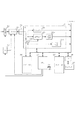
本実施形態のリモート撮影システムは、情報処理装置がカメラ装置とUSBケーブルまたは無線LAN等の通信媒体によって接続され、互いに通信可能である。本実施形態のリモート撮影システムにおいて、カメラ装置を交換レンズ式のデジタルカメラ、情報処理装置をパーソナルコンピュータで実現した例を図1に示す。図1において、カメラ装置102はデジタルカメラのボディであり、レンズ101と結合している。レンズ101は、交換可能であり、焦点距離を可変するためのズームレンズ111、明るさを制御するための絞り機構112、被写体にピントを合わせるためのフォーカスレンズ113を有している。また、この交換式レンズ101は、レンズ側のマウント部114がカメラ装置102のマウント部127と機械的に接合する。カメラ装置102は、レンズを通過してきた光を121のハーフミラーで反射させ、ピント板124の位置で結像させる。ピント板124で結像した光は、プリズム125で反転され、接眼レンズ126を通して正立像として観測できる。また、撮影時には、ハーフミラー121が跳ね上がり、シャッター122が開き、レンズ101を通過してきた光が撮像素子123に結像する。レンズ101のマウント部114には接点群115が組み込まれている。この接点群115はカメラ装置102から電源の供給を受け、通信を行うために接続する部材であり、電源、グランド、送信、受信、クロックなどの用途にそれぞれ分かれている。レンズ101のマウント部114は、カメラ装置102のマウント部127にある接点群128の中の接続端子とそれぞれ接合する。
(First embodiment)
In the remote photographing system of this embodiment, the information processing apparatus is connected to the camera apparatus via a communication medium such as a USB cable or a wireless LAN, and can communicate with each other. FIG. 1 shows an example in which the camera apparatus is realized by an interchangeable lens type digital camera and the information processing apparatus is realized by a personal computer in the remote photographing system of this embodiment. In FIG. 1, a
また、カメラ装置102は接続部103を介してパーソナルコンピュータ140と接続し、各種データを送受信する。そして、カメラ装置102が接続部103を介してパーソナルコンピュータ140へライブビュー画像を送信すると、ディスプレイ141に表示される。また、カメラ装置102は撮影を制御するための各種情報をパーソナルコンピュータ140から受信し、それにしたがって撮影動作を実行する。
Further, the
次に、カメラ装置102の構成を、図2を参照して説明する。撮像素子223は、CCDやCMOS等のセンサーであり、撮像素子223に結像した光は各画素において、入射光量に応じた量の電荷に変換される。タイミングジェネレータ232が発生させる信号は、撮像素子223を駆動し、センサーに蓄積した電荷を伝送し、順次電圧信号に変換される。変換された電圧信号は、相関二重サンプリング(CDS)230でサンプリングされ、A/D変換器231でデジタル信号に変換される。デジタル信号に変換された画像データはIC233に入力され、まず、データに対してホワイトバランスのためのデータを算出するためのWB回路233aに入り、メモリー(1)235に一旦、格納される。のメモリー(1)235に格納されたデータは、再びIC233に入力され、3種類の画像処理を施される。まず、デジタル信号に変換された画像データは、そのままロスレス圧縮(可逆圧縮)をかけるロスレス圧縮回路233dにおいてロスレス圧縮されたRAWデータに変換され、CPUバス234に送出される。また、デジタル信号に変換された画像データはRAWデータをブロック内平均したりローパスフィルタをかけたりして帯域を落とし、そこから間引くことによってダウンサンプリングされる。そして、元の画像サイズより小さいサムネイル画像に変換されるためにRAWサムネイル回路233cで間引き処理され、CPUバス234に送られる。最後に、JPEG圧縮するための画像を作るために、画像処理回路233bにおいて画像処理を施され、その結果、出力されるYcbCrはラスタブロック変換されて、JPEG圧縮回路233eでJPEG圧縮されて、CPUバス234に送られる。Central Processing Unit(CPU)236は、電源が投入された直後、237のメモリー(2)内部のプログラムに従い、カメラ装置102を初期化し、レンズ101との通信を開始する。また、CPU236は撮影された画像データでCPUバス234に出力された画像データを一度、235のメモリー(1)に格納し、インターフェイス回路238を介して外部メモリー239に最終的に書き込む。CPU236につながるスイッチ240はレリーズスイッチであり、スイッチ240の押下を検出することによって上記の撮影の動作が行われ、外部メモリー239に画像が書き込まれる。また、ライブビュー時には、CPU236はハーフミラー221を跳ね上げ、シャッター222を開き、レンズ101を通過してきた光を撮像素子223に結像させ、デジタル信号に変換してライブビュー画像を取得する。そして、ライブビュー画像をメモリー(2)237に保存し、カメラ装置102に設置される背面ディスプレイに表示する。CPU236はライブビュー画像を一定間隔で更新する。撮影者は、光学ファインダーを通して被写体を確認するのと同様に、背面ディスプレイのライブビュー画像によって被写体を確認することができる。また、情報処理装置300からライブビュー機能の実行指示を受けると、CPU236は一定間隔でライブビュー画像を情報処理装置300へ送信する。
Next, the configuration of the
本実施例の情報処理装置を構成するコンピュータ装置の構成を図3を参照して説明する。情報処理装置は単一のコンピュータ装置で実現してもよいし、必要に応じた複数のコンピュータ装置に各機能を分散して実現するようにしてもよい。複数のコンピュータ装置で構成される場合は、互いに通信可能なようにLocal Area Network(LAN)などで接続されている。図3において、301は情報処理装置300全体を制御する制御部であり、例えばCentral Processing Unit(CPU)である。302は変更を必要としないプログラムやパラメータを格納するRead Only Memory(ROM)である。303は外部装置などから供給されるプログラムやデータを一時記憶するRandom Access Memory(RAM)である。304は情報処理装置300に固定して設置されたハードディスクやメモリカード、あるいは情報処理装置300から着脱可能な光ディスクなどを含む外部記憶装置である。外部記憶装置304は、Operating System(OS)やリモート撮影プログラムを記憶している。305はユーザの操作を受け、データを入力するポインティングデバイスやキーボード309などの入力デバイスとのインターフェイスである。306は情報処理装置300の保持するデータや供給されたデータを表示するためのモニタ310とのインターフェイスである。307はネットワーク回線に接続するためのネットワークインタフェイスである。308は301〜307の各ユニットを通信可能に接続するシステムバスである。
The configuration of the computer apparatus that constitutes the information processing apparatus of this embodiment will be described with reference to FIG. The information processing apparatus may be realized by a single computer apparatus, or may be realized by distributing functions to a plurality of computer apparatuses as necessary. When configured by a plurality of computer devices, they are connected by a local area network (LAN) or the like so that they can communicate with each other. In FIG. 3,
本実施形態のリモート撮影システムにおける情報処理装置300の動作を図4を参照して説明する。本実施形態のリモート撮影システムでは、情報処理装置300はカメラ装置102と通信可能に接続され、両方とも電源が入って動作可能な状態にある。なお、以下のカメラ装置102の動作は、CPU236がメモリー(2)237から内部のプログラムを読み出して起動することによって実現される。また、以下の情報処理装置300の動作は、CPU301が外部記憶装置304からOSやリモート撮影プログラムを読み出して起動することによって実現される。
The operation of the
まず、情報処理装置300のCPU301は、カメラ装置で現在、設定されている撮影パラメータをカメラ装置102から受信し(S401)、キャプチャ画面に表示する(S402)。
First, the
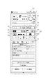
図5に本実施形態のキャプチャ画面を示す。キャプチャ画面500には、カメラ装置102の動作状態や設定値が表示される。例えば、撮影モード501やホワイトバランス502、測光モード503、露出レベル504、記録画質505、シャッター速度506、絞り数値507、ISO感度508などの撮影パラメータの項目が表示される。また、撮影画像の保存場所509、タイマー撮影510などの撮影機能の項目が表示される。また、撮影ボタン511の押下操作があると、CPU301はカメラ装置102に対して撮影指示を行い、撮影画像をカメラ装置102から受信してクイックプレビュー画面に表示する。また、CPU301はユーザの操作に応答して、キャプチャ画面500に表示された項目を再設定し、再設定された内容をカメラ装置102へ通知する。カメラ装置102は通知された内容を適用し、撮影処理を実行する。なお、撮影モードは例えば、撮影時の被写体の状況に応じて自動的に機能設定を行うオート撮影モードや、所定の機能設定を行うシーンモード、ユーザが全て手動で機能設定を行うマニュアル撮影モードがある。また、ユーザが絞り値の設定を行い、シャッター速度は撮影時の被写体の状況に応じて自動的に設定を行う絞り優先モード、逆にユーザがシャッター速度の設定を行い、絞り値は撮影時の被写体の状況に応じて自動的に設定を行う絞り優先モードがある。また、タイマー撮影では、設定された遅延時間を経過すると撮影が行われたり、設定された時間間隔で設定された撮影枚数の撮影が行われる。
FIG. 5 shows a capture screen of this embodiment. On the
次に、CPU301はライブビュー機能が「する」に設定されているか否かを判定し(S403)、「する」に設定されていれば、既にリモートライブビュー画面をディスプレイに141に表示しているか否かを判定する(S404)。未だリモートライブビュー画面が表示されていなければ、CPU301はカメラ装置102にライブビュー機能を実行するよう指示する(S405)。そして、情報処理装置300は、ライブビュー画像を所定の時間間隔でカメラ装置102から受信し(S406)、ライブビュー画像を更新しながらリモートライブビュー画面に表示する(S407)。
Next, the
図6(a)に本実施形態のリモートライブビュー画面を示す。リモートライブビュー画面600はライブビュー領域601と第1の操作部602、第2の操作部603を含む。第1の操作部602は、ホワイトバランス621とフォーカス622、絞り込み623の設定値の入力欄を含む。第2の操作部603はライブビュー領域601の表示内容の選択欄を含む。
FIG. 6A shows a remote live view screen of the present embodiment. The remote live view screen 600 includes a
ユーザがリモートライブビュー画面600の第1の操作部や第2の操作部を操作すると、CPU301はその操作内容に応答して各種処理を実行する(S408)。
When the user operates the first operation unit or the second operation unit of the remote live view screen 600, the
例えば、ユーザがホワイトバランス621を操作して、画像に適用するホワイトバランスの種類を選択すると、CPU301は選択されたホワイトバランスをライブビュー画像に適用して、ライブビュー領域601に表示する。
For example, when the user operates the white balance 621 to select the type of white balance to be applied to the image, the
あるいは、ユーザがホワイトバランス621を操作して、クリックホワイトバランスを起動すると、CPU301はポインタをライブビュー領域601に表示する。ユーザがポインタを移動させて白の基準とする箇所をクリックすると、CPU301はクリックした箇所を白の基準として再度撮影を行うようカメラ装置102に指示する。そして、CPU301は新たに撮影されたライブビュー画像をカメラ装置102から受信して、ライブビュー領域601に表示する。
Alternatively, when the user operates the white balance 621 to activate click white balance, the
あるいは、ユーザがフォーカス622を操作して、AFによるピント合わせを起動すると、CPU301はAFフレームをライブビュー領域601に表示する。ユーザがピントを合わせたい位置にあるAFフレームを選択すると、CPU301は選択されたAFフレームを基準としてピント合わせを行うようカメラ装置102に指示する。そして、CPU301は新たに撮影されたライブビュー画像をカメラ装置102から受信して、ライブビュー領域601に表示する。
Alternatively, when the user operates the
あるいは、ユーザがフォーカス622を操作して、手動ピント合わせを起動し、ライブビュー領域601のライブビュー画像上で拡大したい範囲を指定すると、CPU301は指定された範囲を拡大してライブビュー領域601に表示する。さらにユーザがフォーカス622を操作してピント位置を調整すると、CPU301は調整されたピント位置を基準としてピント合わせを行うようカメラ装置に指示する。そして、CPU301は新たに撮影されたライブビュー画像をカメラ装置102から受信して、ライブビュー領域601に表示する。
Alternatively, when the user operates the
あるいは、ユーザが絞り込み623を操作して、被写界深度と露出の確認を指示すると、CPU301は、キャプチャ画面500の露出レベル504の設定値を反映した明るさでライブビュー画像をライブビュー領域601に表示し、被写界深度を確認し易くする。なお、CPU301は通常、露出レベル504の設値定に関わらず、最も見やすい明るさでライブビュー画像を表示している。
Alternatively, when the user operates the
あるいは、ユーザが第2の操作部603を操作して、グリッド線の表示を指示すると、CPU301はグリッド線をライブビュー画像の上に重ねてライブビュー領域601に表示する。一方、ユーザが第2の操作部を操作して、グリッド線の非表示を指示すると、CPU301はグリッド線をライブビュー領域601から消去する。
Alternatively, when the user operates the
あるいは、ユーザが第2の操作部603を操作して、アスペクト比を指定すると、CPU301は、指定されたアスペクト比と対応する縦線をライブビュー画像の上に重ねてライブビュー領域601に表示する。
Alternatively, when the user operates the
あるいは、ユーザが第2の操作部603を操作して、画像の回転を指示すると、CPU301は、ライブビュー画像を回転してライブビュー領域601に表示する。
Alternatively, when the user operates the
次に、CPU301はキャプチャ画面500やリモートライブビュー画面600上での操作内容を検知し、オーバーレイ表示機能の実行条件を満たしているか否かを判定する(S409)。CPU301は、オーバーレイ表示機能が「する」に設定されており、ステップS408でオーバーレイ表示を許可する操作が実行されていれば実行条件を満たすと判定する。なお、情報処理装置300の外部記憶装置304には、オーバーレイ表示を許可しない操作の種類がリモート撮影プログラムに設定されて格納されている。オーバーレイ表示を許可しない操作の種類は例えば、第1の操作部602のホワイトバランス621を用いたホワイトバランスの調整や、ピント合わせ622を用いたピント位置の調整、絞り込み623を用いた被写界深度と露出の確認等の操作である。よって、オーバーレイ表示を許可する操作の種類はこれら以外となり、例えば、第2の操作部603を用いたグリッド線の表示やアスペクト比の変更、画像の回転等の操作である。また、キャプチャ画面500での撮影パラメータの再設定の操作では、項目毎にオーバーレイ表示の可否がリモート撮影プログラムに設定されて外部記憶装置304に格納されている。そして、オーバーレイ表示機能が「する」に設定されていても、オーバーレイ表示を許可しない操作が実行されている時は、CPU301はオーバーレイ表示機能の実行条件を満たしていないと判定する。
Next, the
なお、本実施形態では、オーバーレイ表示を許可しない操作の種類を外部記憶装置304に格納しておくと説明したが、逆にオーバーレイ表示を許可する操作の種類を格納しておき、ステップS409の判定に用いてもよい。
In the present embodiment, it has been described that the type of operation that does not permit overlay display is stored in the
また、オーバーレイ表示機能が「しない」に設定されていれば、情報処理装置300に対して行われた操作内容に関わらず、CPU301はオーバーレイ表示機能の実行条件を満たしていないと判定する。
If the overlay display function is set to “No”, the
また、オーバーレイ表示機能の実行条件に、カメラ装置102の動作状態を含めてもよい。例えば、CPU301はカメラ装置102から、ピント合わせの動作中など所定種類の動作の実行中であることを通知されると、ステップS409でオーバーレイ表示機能の実行条件を満たさないと判定する。すなわち、オーバーレイ表示機能が「する」に設定され、かつ、カメラ装置102の動作状態および情報処理装置300に対する操作内容がオーバーレイ表示を許可するものであれば、ステップS409でCPU301は実行条件を満たすと判定する。
Further, the operating condition of the
ステップS409でオーバーレイ表示機能の実行条件を満たすと判定されれば、CPU301は、所定の画像を外部記憶装置304から読み出し、所定の透過度になるよう画像処理してオーバーレイ画像を生成する。なお、所定の画像はユーザの操作に応じて選択される。そして、CPU301はオーバーレイ画像をライブビュー画像の上に重ねてライブビュー領域601に表示する(S410)。例えば、図6(b)に示す画像が選択された場合、図6(c)に示すようにオーバーレイ画像をライブビュー画像に重ねて表示する。なお、CPU301は事前にオーバーレイ画像を生成しておいたり、外部機器や他の記憶媒体からオーバーレイ画像を取得したりして、その都度、生成しないようにしてもよい。
If it is determined in step S409 that the execution condition of the overlay display function is satisfied, the
一方、ステップS409でオーバーレイ表示機能の実行条件を満たさないと判定されれば、CPU301は、オーバーレイ画像を非表示にする(S415)。すなわち、既にオーバーレイ画像がライブビュー画像の上に重ねてライブビュー領域601に表示されていれば、CPU301はオーバーレイ画像を消灯し、ライブビュー画像だけを表示する。また、オーバーレイ画像がライブビュー領域601に表示されていなければ、CPU301はそのままライブビュー画像だけをライブビュー領域601に表示する。
On the other hand, if it is determined in step S409 that the overlay display function execution condition is not satisfied, the
そして、CPU301は次の操作の実行が開始されたか否かを検知し(S411)、次の操作の実行が開始されれば、ステップS408に戻って以降の処理を実行し、次の操作の実行が開始されなければ、ステップS403に戻って以降の処理を実行する。
Then, the
一方、ステップS403でライブビュー機能が「しない」に設定されていれば、CPU301はリモートライブビュー画面600をディスプレイ141に表示しているか否かを判定する(S412)。ステップS412で、未だリモートライブビュー画面600を表示していると判定されれば、カメラ装置102にライブビュー機能の実行を中止するよう指示するとともに(S413)、リモートライブビュー画面600を非表示にする(S414)。また、カメラ装置102は、ライブビュー機能の実行中止の指示を受けて、ライブビュー画像の情報処理装置300への送信を中止する。そして、一連の動作が終了する。
On the other hand, if the live view function is set to “NO” in step S403, the
なお、本実施形態では、オーバーレイ表示の実行条件を満たさないときは、オーバーレイ表示を非表示にする場合を説明したが、これに限らず、オーバーレイ画像の透過度を上げて表示し続けるようにしてもよい。さらに、この場合、CPU301は透過度を操作の種類と対応付けて予めリモート撮影プログラムに設定して外部記憶装置304に記憶しておき、元画像を操作の種類と対応する透過度になるよう処理してオーバーレイ画像を生成するようにしてもよい。
In this embodiment, the case where the overlay display is not displayed when the overlay display execution condition is not satisfied has been described. However, the present invention is not limited to this. Also good. Furthermore, in this case, the
上記したように本実施形態では、ライブビュー画像に重ねてオーバーレイ表示を表示するか非表示にするかを操作の種類にしたがって切り替えるようにした。これにより、オーバーレイ表示機能が「する」に設定されていても、ユーザの操作の邪魔になる場合には自動的に非表示となる。したがって、ユーザは手間をかけることなく、ライブビュー画像だけの表示で細部を確認しながら操作をしたり、オーバーレイ表示で構図を確認しながら操作をすることができる。 As described above, in this embodiment, whether to display the overlay display on the live view image or not to display it is switched according to the type of operation. As a result, even if the overlay display function is set to “Yes”, it is automatically hidden when it interferes with the user's operation. Therefore, the user can perform an operation while confirming details by displaying only the live view image, or confirming a composition by overlay display without taking time and effort.
(他の実施形態)
また、本発明は、以下の処理を実行することによっても実現される。即ち、上述した実施形態の機能を実現するソフトウェア(プログラム)を、ネットワーク又は各種記憶媒体を介してシステム或いは装置に供給し、そのシステム或いは装置のコンピュータ(またはCPUやMPU等)がプログラムを読み出して実行する処理である。
(Other embodiments)
The present invention can also be realized by executing the following processing. That is, software (program) that realizes the functions of the above-described embodiments is supplied to a system or apparatus via a network or various storage media, and a computer (or CPU, MPU, or the like) of the system or apparatus reads the program. It is a process to be executed.
Claims (6)
前もってオーバーレイ画像を記憶装置に記憶する記憶手段と、
撮影処理に用いられる撮影指示を前記撮像装置へ送信する送信手段と、
前記撮影指示に基づき前記撮像装置において前記撮影処理を実行することにより取得されたライブビュー画像を受信する受信手段と、
前記受信されたライブビュー画像を画面に表示する第1の表示手段と、
オーバーレイ画像を前記ライブビュー画像に重ねて画面に表示する第2の表示手段と、
ユーザの操作に応答して、前記撮像装置に対する撮影指示の種類を検知する検知手段と、
オーバーレイ画像の表示を許可しない撮影指示の種類を特定するための情報を格納する格納手段を備え、
前記第2の表示手段は、前記検知された撮影指示の種類および前記格納手段に格納された情報にしたがって前記オーバーレイ画像の表示を選択的に中止することを特徴とする情報処理装置。 An information processing device capable of communicating with an imaging device,
Storage means for storing the overlay image in a storage device in advance;
Transmitting means for transmitting a photographing instruction used for photographing processing to the imaging device;
Receiving means for receiving a live view image acquired by executing the shooting process in the imaging apparatus based on the shooting instruction;
First display means for displaying the received live view image on a screen;
Second display means for displaying an overlay image on the screen so as to overlap the live view image;
In response to a user operation, detection means for detecting the type of shooting instruction for the imaging device;
Storage means for storing information for specifying the type of shooting instruction that does not allow display of an overlay image;
The information processing apparatus, wherein the second display unit selectively stops displaying the overlay image according to the type of the detected photographing instruction and the information stored in the storage unit.
前記撮像装置の動作状態毎に前記オーバーレイ画像を前記ライブビュー画像に重ねることにより表示するかどうかを設定する設定手段をさらに備え、
前記第2の表示手段は、さらに前記撮像装置の動作状態のうち少なくとも一方にしたがって、前記オーバーレイ画像の表示を中止することを特徴とする請求項1に記載の情報処理装置。 Receiving means for receiving a notification regarding the operating state of the imaging device;
Further comprising setting means for setting whether to display the overlay image on the live view image for each operation state of the imaging device;
The information processing apparatus according to claim 1, wherein the second display unit further stops displaying the overlay image in accordance with at least one of operation states of the imaging apparatus.
前記画面に表示されるライブビュー画像は新たに受信されたライブビュー画像により更新されることを特徴とする請求項1または2に記載の情報処理装置。 The live view image is received from the imaging device at regular intervals,
The information processing apparatus according to claim 1, wherein the live view image displayed on the screen is updated with a newly received live view image.
前もってオーバーレイ画像を記憶装置に記憶する工程と、
撮影処理に用いられる撮影指示を前記撮像装置へ送信する工程と、
前記撮影指示に基づき前記撮像装置において前記撮影処理を実行することにより取得されたライブビュー画像を受信する工程と、
前記受信されたライブビュー画像を画面に表示する工程と、
オーバーレイ画像を前記ライブビュー画像に重ねて画面に表示する工程と、
ユーザの操作に応答して、前記撮像装置に対する撮影指示の種類を検知する工程と、
オーバーレイ画像の表示を許可しない撮影指示の種類を特定するための情報を格納する工程と、
前記検知された撮影指示の種類および前記格納された情報にしたがって前記オーバーレイ画像の表示を中止する工程とを備えたことを特徴とする制御方法。 An information processing apparatus control method capable of communicating with an imaging apparatus,
Storing the overlay image in a storage device in advance;
Transmitting a photographing instruction used for photographing processing to the imaging device;
Receiving a live view image acquired by executing the shooting process in the imaging apparatus based on the shooting instruction;
Displaying the received live view image on a screen;
Displaying an overlay image on the screen overlaid on the live view image;
In response to a user operation, detecting a type of shooting instruction for the imaging device;
Storing information for identifying the type of shooting instruction that does not allow display of an overlay image;
And a step of stopping the display of the overlay image according to the type of the detected photographing instruction and the stored information.
前もってオーバーレイ画像を記憶装置に記憶する工程と、
撮影処理に用いられる撮影指示を前記撮像装置へ送信する工程と、
前記撮影指示に基づき前記撮像装置において前記撮影処理を実行することにより取得されたライブビュー画像を受信する工程と、
前記受信されたライブビュー画像を画面に表示する工程と、
オーバーレイ画像を前記ライブビュー画像に重ねて画面に表示する工程と、
オーバーレイ画像の表示を許可しない撮影指示の種類を特定するための情報を格納する工程と、
ユーザの操作に応答して、前記撮像装置に対する撮影指示の種類を検知する工程と、
前記検知された撮影指示の種類および前記格納された情報にしたがって前記オーバーレイ画像の表示を中止する工程とを実行させることを特徴とするプログラム。 In a computer that realizes an information processing device that can communicate with an imaging device,
Storing the overlay image in a storage device in advance;
Transmitting a photographing instruction used for photographing processing to the imaging device;
Receiving a live view image acquired by executing the shooting process in the imaging apparatus based on the shooting instruction;
Displaying the received live view image on a screen;
Displaying an overlay image on the screen overlaid on the live view image;
Storing information for identifying the type of shooting instruction that does not allow display of an overlay image;
In response to a user operation, detecting a type of shooting instruction for the imaging device;
And a step of stopping the display of the overlay image according to the type of the detected photographing instruction and the stored information.
Priority Applications (2)
| Application Number | Priority Date | Filing Date | Title |
|---|---|---|---|
| JP2010017009A JP5558852B2 (en) | 2010-01-28 | 2010-01-28 | Information processing apparatus, control method thereof, and program |
| US13/014,661 US9001217B2 (en) | 2010-01-28 | 2011-01-26 | Information processing apparatus, method for displaying live view image, and storage medium storing program therefor |
Applications Claiming Priority (1)
| Application Number | Priority Date | Filing Date | Title |
|---|---|---|---|
| JP2010017009A JP5558852B2 (en) | 2010-01-28 | 2010-01-28 | Information processing apparatus, control method thereof, and program |
Publications (3)
| Publication Number | Publication Date |
|---|---|
| JP2011155595A JP2011155595A (en) | 2011-08-11 |
| JP2011155595A5 JP2011155595A5 (en) | 2013-03-07 |
| JP5558852B2 true JP5558852B2 (en) | 2014-07-23 |
Family
ID=44308689
Family Applications (1)
| Application Number | Title | Priority Date | Filing Date |
|---|---|---|---|
| JP2010017009A Active JP5558852B2 (en) | 2010-01-28 | 2010-01-28 | Information processing apparatus, control method thereof, and program |
Country Status (2)
| Country | Link |
|---|---|
| US (1) | US9001217B2 (en) |
| JP (1) | JP5558852B2 (en) |
Families Citing this family (15)
| Publication number | Priority date | Publication date | Assignee | Title |
|---|---|---|---|---|
| JP5426727B2 (en) * | 2012-06-15 | 2014-02-26 | ファナック株式会社 | Numerical control device for displaying virtual operation panel |
| WO2015071220A1 (en) * | 2013-11-14 | 2015-05-21 | Alpa Capaul & Weber Ag | Camera unit with remote user interface |
| JP6544936B2 (en) * | 2015-01-30 | 2019-07-17 | キヤノン株式会社 | Control device of imaging device, imaging device and control method thereof |
| US9648220B2 (en) * | 2015-03-27 | 2017-05-09 | Panasonic Intellectual Property Management Co., Ltd. | Imaging apparatus, imaging apparatus body and image sound output method |
| US9681111B1 (en) | 2015-10-22 | 2017-06-13 | Gopro, Inc. | Apparatus and methods for embedding metadata into video stream |
| US9667859B1 (en) * | 2015-12-28 | 2017-05-30 | Gopro, Inc. | Systems and methods for determining preferences for capture settings of an image capturing device |
| US9922387B1 (en) | 2016-01-19 | 2018-03-20 | Gopro, Inc. | Storage of metadata and images |
| US9967457B1 (en) | 2016-01-22 | 2018-05-08 | Gopro, Inc. | Systems and methods for determining preferences for capture settings of an image capturing device |
| US9665098B1 (en) | 2016-02-16 | 2017-05-30 | Gopro, Inc. | Systems and methods for determining preferences for flight control settings of an unmanned aerial vehicle |
| US9973792B1 (en) | 2016-10-27 | 2018-05-15 | Gopro, Inc. | Systems and methods for presenting visual information during presentation of a video segment |
| US10187607B1 (en) | 2017-04-04 | 2019-01-22 | Gopro, Inc. | Systems and methods for using a variable capture frame rate for video capture |
| US11526935B1 (en) | 2018-06-13 | 2022-12-13 | Wells Fargo Bank, N.A. | Facilitating audit related activities |
| JP7458730B2 (en) | 2019-09-30 | 2024-04-01 | キヤノン株式会社 | Information processing device, control method for information processing device, and program thereof |
| JP7379052B2 (en) | 2019-09-30 | 2023-11-14 | キヤノン株式会社 | Display control device, method and program |
| US11503206B2 (en) | 2020-07-15 | 2022-11-15 | Sony Corporation | Techniques for providing photographic context assistance |
Family Cites Families (14)
| Publication number | Priority date | Publication date | Assignee | Title |
|---|---|---|---|---|
| US5986718A (en) * | 1996-09-19 | 1999-11-16 | Video Magic, Inc. | Photographic method using chroma-key and a photobooth employing the same |
| US7136096B1 (en) * | 1998-03-11 | 2006-11-14 | Canon Kabushiki Kaisha | Image processing method and apparatus, control method therefor, and storage medium |
| JP3169888B2 (en) * | 1998-03-25 | 2001-05-28 | エヌイーシービューテクノロジー株式会社 | Digital image reproducing apparatus, image reproducing method, and recording medium storing image reproducing program |
| WO2003003720A1 (en) * | 2001-06-28 | 2003-01-09 | Omnivee Inc. | Method and apparatus for control and processing of video images |
| AU2003246268A1 (en) * | 2002-08-09 | 2004-02-25 | Sharp Kabushiki Kaisha | Image combination device, image combination method, image combination program, and recording medium containing the image combination program |
| JP4059241B2 (en) | 2004-10-29 | 2008-03-12 | カシオ計算機株式会社 | Subject photographing method and camera apparatus |
| US7782384B2 (en) * | 2004-11-05 | 2010-08-24 | Kelly Douglas J | Digital camera having system for digital image composition and related method |
| JP2006352255A (en) | 2005-06-13 | 2006-12-28 | Canon Inc | Image input system and its power supply alteration method and program |
| CA2636010A1 (en) * | 2006-01-17 | 2007-07-17 | Baker Hughes Inc | System and method for remote data acquisition and distribution |
| US20140011428A1 (en) * | 2006-10-17 | 2014-01-09 | Mattel, Inc. | Toy Having Point-of-View Video Recording and Editing |
| JP4943899B2 (en) * | 2007-03-05 | 2012-05-30 | 株式会社日立国際電気 | Image display method and image display program |
| US20100275122A1 (en) * | 2009-04-27 | 2010-10-28 | Microsoft Corporation | Click-through controller for mobile interaction |
| US8830267B2 (en) * | 2009-11-16 | 2014-09-09 | Alliance For Sustainable Energy, Llc | Augmented reality building operations tool |
| US20110153341A1 (en) * | 2009-12-17 | 2011-06-23 | General Electric Company | Methods and systems for use of augmented reality to improve patient registration in medical practices |
-
2010
- 2010-01-28 JP JP2010017009A patent/JP5558852B2/en active Active
-
2011
- 2011-01-26 US US13/014,661 patent/US9001217B2/en active Active
Also Published As
| Publication number | Publication date |
|---|---|
| JP2011155595A (en) | 2011-08-11 |
| US20110181739A1 (en) | 2011-07-28 |
| US9001217B2 (en) | 2015-04-07 |
Similar Documents
| Publication | Publication Date | Title |
|---|---|---|
| JP5558852B2 (en) | Information processing apparatus, control method thereof, and program | |
| JP4613724B2 (en) | Imaging apparatus and imaging method | |
| JP2013013050A (en) | Imaging apparatus and display method using imaging apparatus | |
| JP5436019B2 (en) | Control device, control method, program, and recording medium | |
| EP2690861B1 (en) | Apparatus and method to photograph an image | |
| US20180198988A1 (en) | Imaging device and system including imaging device and server | |
| US10491835B2 (en) | Imaging apparatus, method for controlling imaging apparatus, method for controlling display control apparatus, and method for controlling recording apparatus | |
| JP2007081465A (en) | Remote controller and imaging apparatus | |
| US20100033582A1 (en) | Method and apparatus for controlling thumbnail display and digital photographing apparatus | |
| JP4941758B2 (en) | Imaging device | |
| JP2014068081A (en) | Imaging apparatus and control method of the same, program and storage medium | |
| JP5868038B2 (en) | Imaging apparatus, control method therefor, program, and storage medium | |
| JP2020187239A (en) | Imaging apparatus, control method of imaging apparatus, program and storage medium | |
| US9930267B2 (en) | Image pickup apparatus that automatically generates time-lapse moving image, moving image generation method, and storage medium | |
| JP2006303967A (en) | Imaging device and its control method | |
| JP6376753B2 (en) | Imaging apparatus, display control apparatus control method, and recording apparatus control method | |
| JP2011049661A (en) | Information processing apparatus, image pickup apparatus and program | |
| JP5800280B2 (en) | Imaging apparatus, imaging condition control method, program | |
| JP2019110366A (en) | Image capture device capable of overlay display control | |
| WO2019181578A1 (en) | Imaging device, inter-exposure zoom photographing method, program, and recording medium | |
| KR20110060299A (en) | A digital photographing apparatus, a method for controlling the same, and a computer-readable medium | |
| JP2011078056A (en) | Camera | |
| KR20130092213A (en) | Digital photographing apparatus and control method thereof | |
| US11625948B2 (en) | Imaging control apparatus capable of selecting detected subject and method for the same | |
| JP7137710B2 (en) | Imaging device, imaging device, operating method of imaging device, and program |
Legal Events
| Date | Code | Title | Description |
|---|---|---|---|
| A521 | Request for written amendment filed |
Free format text: JAPANESE INTERMEDIATE CODE: A523 Effective date: 20130123 |
|
| A621 | Written request for application examination |
Free format text: JAPANESE INTERMEDIATE CODE: A621 Effective date: 20130123 |
|
| A977 | Report on retrieval |
Free format text: JAPANESE INTERMEDIATE CODE: A971007 Effective date: 20131219 |
|
| A131 | Notification of reasons for refusal |
Free format text: JAPANESE INTERMEDIATE CODE: A131 Effective date: 20140114 |
|
| A521 | Request for written amendment filed |
Free format text: JAPANESE INTERMEDIATE CODE: A523 Effective date: 20140317 |
|
| TRDD | Decision of grant or rejection written | ||
| A01 | Written decision to grant a patent or to grant a registration (utility model) |
Free format text: JAPANESE INTERMEDIATE CODE: A01 Effective date: 20140507 |
|
| A61 | First payment of annual fees (during grant procedure) |
Free format text: JAPANESE INTERMEDIATE CODE: A61 Effective date: 20140605 |
|
| R151 | Written notification of patent or utility model registration |
Ref document number: 5558852 Country of ref document: JP Free format text: JAPANESE INTERMEDIATE CODE: R151 |