JP5558552B2 - Control method for vehicle brake device - Google Patents
Control method for vehicle brake device Download PDFInfo
- Publication number
- JP5558552B2 JP5558552B2 JP2012501808A JP2012501808A JP5558552B2 JP 5558552 B2 JP5558552 B2 JP 5558552B2 JP 2012501808 A JP2012501808 A JP 2012501808A JP 2012501808 A JP2012501808 A JP 2012501808A JP 5558552 B2 JP5558552 B2 JP 5558552B2
- Authority
- JP
- Japan
- Prior art keywords
- cylinder
- brake
- fluid
- wheel
- valve
- Prior art date
- Legal status (The legal status is an assumption and is not a legal conclusion. Google has not performed a legal analysis and makes no representation as to the accuracy of the status listed.)
- Expired - Fee Related
Links
Images


Classifications
-
- B—PERFORMING OPERATIONS; TRANSPORTING
- B60—VEHICLES IN GENERAL
- B60T—VEHICLE BRAKE CONTROL SYSTEMS OR PARTS THEREOF; BRAKE CONTROL SYSTEMS OR PARTS THEREOF, IN GENERAL; ARRANGEMENT OF BRAKING ELEMENTS ON VEHICLES IN GENERAL; PORTABLE DEVICES FOR PREVENTING UNWANTED MOVEMENT OF VEHICLES; VEHICLE MODIFICATIONS TO FACILITATE COOLING OF BRAKES
- B60T7/00—Brake-action initiating means
- B60T7/02—Brake-action initiating means for personal initiation
- B60T7/04—Brake-action initiating means for personal initiation foot actuated
- B60T7/042—Brake-action initiating means for personal initiation foot actuated by electrical means, e.g. using travel or force sensors
-
- B—PERFORMING OPERATIONS; TRANSPORTING
- B60—VEHICLES IN GENERAL
- B60T—VEHICLE BRAKE CONTROL SYSTEMS OR PARTS THEREOF; BRAKE CONTROL SYSTEMS OR PARTS THEREOF, IN GENERAL; ARRANGEMENT OF BRAKING ELEMENTS ON VEHICLES IN GENERAL; PORTABLE DEVICES FOR PREVENTING UNWANTED MOVEMENT OF VEHICLES; VEHICLE MODIFICATIONS TO FACILITATE COOLING OF BRAKES
- B60T13/00—Transmitting braking action from initiating means to ultimate brake actuator with power assistance or drive; Brake systems incorporating such transmitting means, e.g. air-pressure brake systems
- B60T13/10—Transmitting braking action from initiating means to ultimate brake actuator with power assistance or drive; Brake systems incorporating such transmitting means, e.g. air-pressure brake systems with fluid assistance, drive, or release
- B60T13/66—Electrical control in fluid-pressure brake systems
- B60T13/662—Electrical control in fluid-pressure brake systems characterised by specified functions of the control system components
-
- B—PERFORMING OPERATIONS; TRANSPORTING
- B60—VEHICLES IN GENERAL
- B60T—VEHICLE BRAKE CONTROL SYSTEMS OR PARTS THEREOF; BRAKE CONTROL SYSTEMS OR PARTS THEREOF, IN GENERAL; ARRANGEMENT OF BRAKING ELEMENTS ON VEHICLES IN GENERAL; PORTABLE DEVICES FOR PREVENTING UNWANTED MOVEMENT OF VEHICLES; VEHICLE MODIFICATIONS TO FACILITATE COOLING OF BRAKES
- B60T13/00—Transmitting braking action from initiating means to ultimate brake actuator with power assistance or drive; Brake systems incorporating such transmitting means, e.g. air-pressure brake systems
- B60T13/10—Transmitting braking action from initiating means to ultimate brake actuator with power assistance or drive; Brake systems incorporating such transmitting means, e.g. air-pressure brake systems with fluid assistance, drive, or release
- B60T13/66—Electrical control in fluid-pressure brake systems
- B60T13/68—Electrical control in fluid-pressure brake systems by electrically-controlled valves
- B60T13/686—Electrical control in fluid-pressure brake systems by electrically-controlled valves in hydraulic systems or parts thereof
-
- B—PERFORMING OPERATIONS; TRANSPORTING
- B60—VEHICLES IN GENERAL
- B60T—VEHICLE BRAKE CONTROL SYSTEMS OR PARTS THEREOF; BRAKE CONTROL SYSTEMS OR PARTS THEREOF, IN GENERAL; ARRANGEMENT OF BRAKING ELEMENTS ON VEHICLES IN GENERAL; PORTABLE DEVICES FOR PREVENTING UNWANTED MOVEMENT OF VEHICLES; VEHICLE MODIFICATIONS TO FACILITATE COOLING OF BRAKES
- B60T8/00—Arrangements for adjusting wheel-braking force to meet varying vehicular or ground-surface conditions, e.g. limiting or varying distribution of braking force
- B60T8/26—Arrangements for adjusting wheel-braking force to meet varying vehicular or ground-surface conditions, e.g. limiting or varying distribution of braking force characterised by producing differential braking between front and rear wheels
- B60T8/266—Arrangements for adjusting wheel-braking force to meet varying vehicular or ground-surface conditions, e.g. limiting or varying distribution of braking force characterised by producing differential braking between front and rear wheels using valves or actuators with external control means
-
- B—PERFORMING OPERATIONS; TRANSPORTING
- B60—VEHICLES IN GENERAL
- B60T—VEHICLE BRAKE CONTROL SYSTEMS OR PARTS THEREOF; BRAKE CONTROL SYSTEMS OR PARTS THEREOF, IN GENERAL; ARRANGEMENT OF BRAKING ELEMENTS ON VEHICLES IN GENERAL; PORTABLE DEVICES FOR PREVENTING UNWANTED MOVEMENT OF VEHICLES; VEHICLE MODIFICATIONS TO FACILITATE COOLING OF BRAKES
- B60T8/00—Arrangements for adjusting wheel-braking force to meet varying vehicular or ground-surface conditions, e.g. limiting or varying distribution of braking force
- B60T8/32—Arrangements for adjusting wheel-braking force to meet varying vehicular or ground-surface conditions, e.g. limiting or varying distribution of braking force responsive to a speed condition, e.g. acceleration or deceleration
- B60T8/34—Arrangements for adjusting wheel-braking force to meet varying vehicular or ground-surface conditions, e.g. limiting or varying distribution of braking force responsive to a speed condition, e.g. acceleration or deceleration having a fluid pressure regulator responsive to a speed condition
- B60T8/40—Arrangements for adjusting wheel-braking force to meet varying vehicular or ground-surface conditions, e.g. limiting or varying distribution of braking force responsive to a speed condition, e.g. acceleration or deceleration having a fluid pressure regulator responsive to a speed condition comprising an additional fluid circuit including fluid pressurising means for modifying the pressure of the braking fluid, e.g. including wheel driven pumps for detecting a speed condition, or pumps which are controlled by means independent of the braking system
- B60T8/4072—Systems in which a driver input signal is used as a control signal for the additional fluid circuit which is normally used for braking
- B60T8/4081—Systems with stroke simulating devices for driver input
Landscapes
- Engineering & Computer Science (AREA)
- Transportation (AREA)
- Mechanical Engineering (AREA)
- Physics & Mathematics (AREA)
- Fluid Mechanics (AREA)
- Regulating Braking Force (AREA)
- Braking Systems And Boosters (AREA)
- Valves And Accessory Devices For Braking Systems (AREA)
Description
本発明は、運転者によるブレーキペダルの操作を電気信号に変換し、その電気信号に基づいて制御されるスレーブシリンダが発生するブレーキ液圧でホイールシリンダを作動させる、いわゆるBBW(ブレーキ・バイ・ワイヤ)式の車両用ブレーキ装置の制御方法に関する。 The present invention converts a brake pedal operation by a driver into an electric signal, and operates a wheel cylinder with a brake hydraulic pressure generated by a slave cylinder controlled based on the electric signal, so-called BBW (brake-by-wire). ) type of relate to control how the brake equipment for the vehicle.
かかるBBW式の車両用ブレーキ装置において、タンデム式のマスタシリンダと、タンデム式のスレーブシリンダと、第1系統のホイールシリンダと、第2系統のホイールシリンダとを備え、マスタシリンダの第1液圧室をスレーブシリンダの第1液圧室を介して第1系統のホイールシリンダに接続するとともに、マスタシリンダの第2液圧室をスレーブシリンダの第2液圧室を介して第1系統のホイールシリンダに接続し、システムの正常時にはスレーブシリンダが発生するブレーキ液圧で第1、第2系統のホイールシリンダを作動させ、システムの異常時にはマスタシリンダが発生するブレーキ液圧で第1、第2系統のホイールシリンダを作動させるものが、下記特許文献1により公知である。
The BBW type vehicle brake device includes a tandem master cylinder, a tandem slave cylinder, a first system wheel cylinder, and a second system wheel cylinder, and a first hydraulic chamber of the master cylinder. Is connected to the first system wheel cylinder through the first hydraulic chamber of the slave cylinder, and the second hydraulic chamber of the master cylinder is connected to the first system wheel cylinder through the second hydraulic chamber of the slave cylinder. Connect and operate the first and second wheel cylinders with the brake fluid pressure generated by the slave cylinder when the system is normal, and the first and second wheels with the brake fluid pressure generated by the master cylinder when the system is abnormal The thing which operates a cylinder is well-known by the following
しかしながら、上記従来のものは、第1系統のホイールシリンダおよび第2系統のホイールシリンダに対応してスレーブシリンダが第1、第2液圧室を備える必要があるため、スレーブシリンダの構造が複雑化してコストアップの要因となる問題がある。これを解消するために、単一の液圧室を備えるスレーブシリンダから第1、第2系統のホイールシリンダにブレーキ液圧を供給するように構成すると、スレーブシリンダが失陥してマスタシリンダが発生するブレーキ液圧でホイールシリンダを作動させる場合に、第1、第2系統の一方の系統のホイールシリンダに液漏れ等の失陥が発生すると、第1、第2系統の両方のホイールシリンダの制動力が失われてしまう可能性がある。 However, in the above-described conventional one, since the slave cylinder needs to include the first and second hydraulic pressure chambers corresponding to the first system wheel cylinder and the second system wheel cylinder, the structure of the slave cylinder becomes complicated. There is a problem that causes cost increase. To solve this problem, when the brake fluid pressure is supplied from the slave cylinder having a single fluid pressure chamber to the wheel cylinders of the first and second systems, the slave cylinder fails and the master cylinder is generated. When the wheel cylinder is operated with the brake fluid pressure applied, if a failure such as liquid leakage occurs in the wheel cylinder of one of the first and second systems, the wheel cylinders of both the first and second systems are controlled. Power may be lost.
本発明は前述の事情に鑑みてなされたもので、BBW式のブレーキ装置において、単一の液圧室を備える簡単な構造のスレーブシリンダで、二つのブレーキ系統の一方の系統が失陥したときのバックアップを可能にすることを目的とする。 The present invention has been made in view of the above circumstances, and in a BBW type brake device, a slave cylinder having a simple structure having a single hydraulic chamber, when one of the two brake systems fails. The purpose of this is to enable backup.
上記目的を達成するために、本発明によれば、ブレーキペダルにより作動して2系統のブレーキ液圧を発生するマスタシリンダと、前記マスタシリンダの少なくとも一つの出力ポートに接続され該マスタシリンダからのブレーキ液を導入するストロークシミュレータと、前記マスタシリンダの第1液圧室と第1系統のホイールシリンダとを接続する第1液路と、前記マスタシリンダの第2液圧室と第2系統のホイールシリンダとを接続する第2液路と、前記第1液路に接続されてアクチュエータの駆動力でブレーキ液圧を発生するスレーブシリンダと、前記スレーブシリンダよりも上流側の前記第1、第2液路のそれぞれに設けられて前記マスタシリンダおよび前記第1、第2系統のホイールシリンダ間の連通をそれぞれ遮断可能な第1、第2マスタカットバルブと、前記第1、第2マスタカットバルブよりも下流側で前記第1、第2液路を連通させる第3液路と、前記第3液路を遮断可能な連通制御バルブとを備える車両用ブレーキ装置の作動を制御する制御方法であって、前記連通制御バルブを閉弁し、前記第1、第2液路のうちの前記スレーブシリンダ側の液路に配置される前記マスタカットバルブを閉弁して他方の液路の前記マスタカットバルブを開弁した状態で、前記スレーブシリンダが発生するブレーキ液圧を前記第1、第2液路のうちの前記スレーブシリンダ側の液路に伝達する工程を含むことを特徴とする車両用ブレーキ装置の制御方法が提案される。 In order to achieve the above object, according to the present invention, a master cylinder that is operated by a brake pedal to generate two systems of brake fluid pressure, and is connected to at least one output port of the master cylinder, is connected to the master cylinder. A stroke simulator for introducing brake fluid, a first fluid passage connecting the first hydraulic chamber of the master cylinder and the first wheel cylinder, the second hydraulic chamber of the master cylinder and the second wheel A second fluid path connecting the cylinder, a slave cylinder connected to the first fluid path and generating a brake fluid pressure by a driving force of an actuator, and the first and second fluids upstream of the slave cylinder. First and second, which are provided on each of the paths and can respectively cut off communication between the master cylinder and the first and second wheel cylinders. A master cut valve; a third liquid path for communicating the first and second liquid paths downstream of the first and second master cut valves; and a communication control valve capable of blocking the third liquid path. a comprises Ru car dual brake system control to that control how the operation of, closed the communication control valve, the first, is arranged on the slave cylinder side of the liquid passage of the second fluid path With the master cut valve closed and the master cut valve of the other fluid passage opened, the brake fluid pressure generated by the slave cylinder is set to the slave cylinder side of the first and second fluid passages. control how are proposals in that it comprises the step of transmitting to the liquid path vehicle brake system according to feature.
尚、実施の形態の第1出力ポート21は本発明の出力ポートに対応する。
The
本発明の特徴によれば、連通制御バルブを閉弁し、第1、第2液路のうちのスレーブシリンダ側の液路に配置されるマスタカットバルブを閉弁して他方の液路のマスタカットバルブを開弁した状態で、スレーブシリンダが発生するブレーキ液圧を第1、第2液路のうちの前記スレーブシリンダ側の液路に伝達するので、第1、第2系統の一方の系統のホイールシリンダに液漏れ等の失陥が発生した場合には、他方の系統のホイールシリンダにマスタシリンダからのブレーキ液圧を供給可能にし、また第1、第2系統の他方の系統のホイールシリンダに液漏れ等の失陥が発生した場合には、一方の系統のホイールシリンダにスレーブシリンダからのブレーキ液圧を供給可能にすることができる。 According to features of the present invention, it closes the communication control valve, first, the other liquid passage and closes the master cut valve that is disposed in the slave cylinder side of the liquid passage of the second fluid path With the master cut valve opened, the brake fluid pressure generated by the slave cylinder is transmitted to the fluid path on the slave cylinder side of the first and second fluid paths, so one of the first and second systems When a failure such as liquid leakage occurs in the wheel cylinder of this system, the brake fluid pressure from the master cylinder can be supplied to the wheel cylinder of the other system, and the other system of the first and second systems When a failure such as liquid leakage occurs in the wheel cylinder, the brake hydraulic pressure from the slave cylinder can be supplied to the wheel cylinder of one system .
11 マスタシリンダ
12 ブレーキペダル
17 第1液圧室
19 第2液圧室
21 第1出力ポート(出力ポート)
26,27 第1系統のホイールシリンダ
30,31 第2系統のホイールシリンダ
32 第1マスタカットバルブ
33 第2マスタカットバルブ
35 ストロークシミュレータ
41 連通制御バルブ
42 スレーブシリンダ
43 アクチュエータ
Pa〜Pd 第1液路
Qa〜Qd 第2液路
Rc 第3液路
11
26 and 27 the first
P A~Pd first liquid passage Qa~Qd second fluid path Rc third liquid passage
以下、図1〜図6に基づいて本発明の実施の形態を説明する。 Hereinafter, embodiments of the present invention will be described with reference to FIGS.
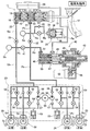
図1に示すように、タンデム型のマスタシリンダ11は、運転者が操作するブレーキペダル12にプッシュロッド13を介して接続された第1ピストン14と、その前方に配置された第2ピストン15とを備えており、第1ピストン14および第2ピストン15間にリターンスプリング16が収納された第1液圧室17が区画され、第2ピストン15の前方にリターンスプリング18が収納された第2液圧室19が区画される。リザーバ20に連通可能な第1液圧室17および第2液圧室19はそれぞれ第1出力ポート21および第2出力ポート22を備えており、第1出力ポート21は液路Pa、液路Pb、液圧モジュレータ23および液路Pc,Pdを介して、例えば左右の後輪のディスクブレーキ装置24,25のホイールシリンダ26,27(第1系統)に接続されるとともに、第2出力ポート22は液路Qa、液路Qb、液圧モジュレータ23および液路Qc,Qdを介して、例えば左右の前輪のディスクブレーキ装置28,29のホイールシリンダ30,31(第2系統)に接続される。
As shown in FIG. 1, a
尚、本明細書で、液路Pa〜Pdおよび液路Qa〜Qdの上流側とはマスタシリンダ11側を意味し、下流側とはホイールシリンダ26,27;30,31側を意味するものとする。
In the present specification, the upstream side of the fluid paths Pa to Pd and the fluid paths Qa to Qd means the
液路Pa,Pb間に常開型電磁弁である第1マスタカットバルブ32が配置され、液路Qa,Qb間に常開型電磁弁である第2マスタカットバルブ33が配置される。第1マスタカットバルブ32の上流側の液路Paから分岐する液路Ra,Rbは、常閉型電磁弁であるシミュレータバルブ34を介してストロークシミュレータ35が接続される。ストロークシミュレータ35は、シリンダ36にスプリング37で付勢されたピストン38を摺動自在に嵌合させたもので、ピストン38の反スプリング37側に形成された液圧室39が第3液路Rbに連通する。シミュレータバルブ34には、ストロークシミュレータ35側から液路Pa側へのブレーキ液の流通のみを許容するチェックバルブ40が並列に接続される。
A first
第1、第2マスタカットバルブ32,33の下流側の液路Pbおよび液路Qbを相互に接続する第3液路Rcに常閉型電磁弁である連通制御バルブ41が配置され、液路Pbから分岐する液路Rdにスレーブシリンダ42が接続される。スレーブシリンダ42を作動させるアクチュエータ43は、電動モータ44の回転をギヤ列45を介してボールねじ機構46に伝達する。スレーブシリンダ42はマスタシリンダ11のリザーバ20に液路Reを介して接続されたシリンダ本体47を備えており、シリンダ本体47に摺動自在に嵌合するピストン48はリターンスプリング49で後退方向に付勢される。アクチュエータ43のボールねじ機構46でピストン48を前進方向に駆動すると、液圧室50に発生したブレーキ液圧が出力ポート51を介して液路Rdに伝達される。
A
ABS(アンチロック・ブレーキ・システム)およびVSA(ビークル・スタビリティ・アシスト)の機能を備えた液圧モジュレータ23の構造は周知のもので、左右の後輪のディスクブレーキ装置24,25の系統と、左右の前輪のディスクブレーキ装置28,29の系統とに同じ構造のものが設けられる。その代表として左右の後輪のディスクブレーキ装置24,25の系統について説明すると、液路Pbと液路Pc,Pdとの間に一対の常開型電磁弁よりなるインバルブ52,52が配置され、インバルブ52,52の下流側の液路Pc,Pdとリザーバ53との間に常閉型電磁弁よりなるアウトバルブ54,54が配置される。リザーバ53と液路Pbとの間に液圧ポンプ55が配置されており、この液圧ポンプ55は電動モータ56により駆動される。
The structure of the
各液圧ポンプ55の吸入側および吐出側には、リザーバ53側から液路Pb,Qb側へのブレーキ液の流通のみを許容するチェックバルブ57,58が配置される。また各インバルブ62には、液路Pc,Pd;Qc,Qd側から液路Pb,Qb側へのブレーキ液の流通のみを許容するチェックバルブ59…が並列に接続される。
On the suction side and the discharge side of each
液路Paには、その液圧を検出する第1液圧センサSaが接続され、液路Qbには、その液圧を検出する第2液圧センサSbが接続される。第1、第2マスタカットバルブ32,33、シミュレータバルブ34、連通制御バルブ41、スレーブシリンダ42および液圧モジュレータ23に接続された不図示の電子制御ユニットには、前記第1液圧センサSaと、前記第2液圧センサSbと、各車輪の車輪速を検出する車輪速センサSc…とが接続される。
A first fluid pressure sensor Sa that detects the fluid pressure is connected to the fluid passage Pa, and a second fluid pressure sensor Sb that detects the fluid pressure is connected to the fluid passage Qb. The electronic control unit (not shown) connected to the first and second
次に、上記構成を備えた本発明の実施の形態の作用について説明する。 Next, the operation of the embodiment of the present invention having the above configuration will be described.
先ず、図2に基づいて正常時における通常の制動作用について説明する。 First, a normal braking action at normal time will be described based on FIG.
システムが正常に機能する正常時に、液路Paに設けた第1液圧センサSaが運転者によるブレーキペダル12の踏み込みを検出すると、常開型電磁弁よりなる第1、第2マスタカットバルブ32,33が励磁されて閉弁し、常閉型電磁弁よりなるシミュレータバルブ34が励磁されて開弁し、常閉型電磁弁よりなる連通制御バルブ41が励磁されて開弁する。これと同時にスレーブシリンダ42のアクチュエータ43が作動してピストン48が前進することで、液圧室50にブレーキ液圧が発生する。このとき、常閉型電磁弁よりなる連通制御バルブ41は励磁されて開弁しているため、スレーブシリンダ42が発生したブレーキ液圧は液路Pbと、その液路Pbに第3液路Rcを介して接続された液路Qbとに伝達され、両液路Pb,Qbから液圧モジュレータ23の開弁したインバルブ52…を介してディスクブレーキ装置24,25;28,29のホイールシリンダ26,27;30,31に伝達されて各車輪を制動する。
When the system normally functions, when the first hydraulic pressure sensor Sa provided in the fluid path Pa detects that the driver depresses the
またマスタシリンダ11の第1液圧室17が発生したブレーキ液圧は開弁したシミュレータバルブ34を介してストロークシミュレータ35の液圧室39に伝達され、そのピストン38をスプリング37に抗して移動させることで、ブレーキペダル12のストロークを許容するとともに擬似的なペダル反力を発生させて運転者の違和感を解消することができる。
The brake hydraulic pressure generated in the first hydraulic pressure chamber 17 of the
そして液路Qbに設けた液圧センサSbで検出したスレーブシリンダ42によるブレーキ液圧が、液路Paに設けた液圧センサSaで検出したマスタシリンダ11によるブレーキ液圧に応じた大きさになるように、スレーブシリンダ42のアクチュエータ43の作動を制御することで、運転者がブレーキペダル12に入力する操作量に応じた制動力をディスクブレーキ装置24,25;28,29に発生させることができる。
Then, the brake fluid pressure by the
また第1系統(後輪)のホイールシリンダ30,31に伝達されるブレーキ液圧と、第2系統(前輪)のホイールシリンダ26,27に伝達されるブレーキ液圧とを過渡的に異ならせたい場合には、可変開度の連通制御バルブ41を任意の中間開度に開弁することで、前輪の制動力を後輪の制動力よりも低くすることができる。
In addition, the brake hydraulic pressure transmitted to the
また、例えば前輪がモータ・ジェネレータで駆動されるハイブリッド車両の場合には、車両の減速時にモータ・ジェネレータを回生制動することにより発生する制動力の分だけ、モータ・ジェネレータに接続された前輪の液圧制動力を低減してトータルの制動力を目標値に一致させる制御が行われる。このような場合に、上述したように、連通制御バルブ41の所定の中間開度に制御することにより、前輪の液圧制動力を過渡的に低減制御することができる。
Further, for example, in the case of a hybrid vehicle in which the front wheels are driven by a motor / generator, the liquid in the front wheels connected to the motor / generator is equivalent to the braking force generated by regenerative braking of the motor / generator during deceleration of the vehicle. Control is performed to reduce the pressure braking force so that the total braking force matches the target value. In such a case, as described above, the hydraulic braking force of the front wheels can be transiently reduced and controlled by controlling the
次に、図3に基づいて正常時におけるABS制御の作用について説明する。 Next, the operation of the ABS control in the normal state will be described based on FIG.
上述した正常時における制動中に、車輪速センサSc…の出力に基づいて何れかの車輪のスリップ率が増加してロック傾向になったことが検出されると、スレーブシリンダ42を作動状態に維持し、この状態で液圧モジュレータ23を作動させて車輪のロックを防止する。
During the above-described normal braking, when it is detected that the slip ratio of any wheel has increased due to the output of the wheel speed sensor Sc ..., the
即ち、所定の車輪がロック傾向になると、その車輪のディスクブレーキ装置のホイールシリンダに連なるインバルブ52を閉弁してスレーブシリンダ42からのブレーキ液圧の伝達を遮断した状態で、アウトバルブ54を開弁してホイールシリンダのブレーキ液圧をリザーバ53に逃がす減圧作用と、それに続いてアウトバルブ54を閉弁してホイールシリンダのブレーキ液圧を保持する保持作用とを行うことで、車輪がロックしないように制動力を低下させる。
That is, when a predetermined wheel tends to be locked, the in-
その結果、車輪速度が回復してスリップ率が低下すると、インバルブ52を開弁してホイールシリンダのブレーキ液圧が増加させる増圧作用を行うことで、車輪の制動力を増加させる。この増圧作用により車輪が再びロック傾向になると、前記減圧、保持、増圧を再び実行し、その繰り返しにより車輪のロックを抑制しながら最大限の制動力を発生させることができる。その間にリザーバ53に流入したブレーキ液は、液圧ポンプ55により上流側の液路Pb,Qbに戻される。
As a result, when the wheel speed recovers and the slip ratio decreases, the braking force of the wheel is increased by opening the in-
図3には、左後輪のホイールシリンダ26のブレーキ液圧が保持され、右後輪のホイールシリンダ27のブレーキ液圧が減圧され、左右の前輪のホイールシリンダ30,31のブレーキ液圧が増圧される状態が示される。
In FIG. 3, the brake fluid pressure of the left rear
次に、図4に基づいて正常時におけるVSA制御の作用について説明する。 Next, the operation of the VSA control at the normal time will be described based on FIG.
VSA制御は、旋回内輪の制動力と旋回外輪の制動力とを異ならせることでヨーモーメントを発生させ、このヨーモーメントで車両の横滑りを防止して挙動の安定を図るものである。前記ABS制御が制動時に限って行われるのに対し、VSA制御は車両の旋回時であれば制動を伴わない場合にも行われる点で異なっている。尚、本実施の形態においては、四輪に対して独立に加圧・減圧制御を実施する態様としてVSAの動作に基づく制御を示すが、四輪に対して独立に加圧・減圧制御を実施する態様は、VSAの実行中に限られるものではない。個々の車輪のホイールシリンダ26,27;30,31に伝達されるブレーキ液圧の減圧、保持、増圧の作用は上述したABS制御の場合と同様であるが、通常のVSA制御に対し、スレーブシリンダ42の駆動量を制御することにより調圧が可能となるため、液圧ポンプ55,55は加圧機能を省略でき、還流のみを機能とすることができる。
In the VSA control, a yaw moment is generated by making the braking force of the inner turning wheel different from the braking force of the outer turning wheel, and the side slip of the vehicle is prevented by this yaw moment to stabilize the behavior. The ABS control is performed only at the time of braking, whereas the VSA control is different when the vehicle is turning even when braking is not performed. In this embodiment, the control based on the operation of the VSA is shown as a mode in which the pressurization / decompression control is independently performed on the four wheels, but the pressurization / depressurization control is independently performed on the four wheels. The mode to perform is not limited to the execution of VSA. The brake fluid pressure transmitted to the
図4には、左後輪のホイールシリンダ26のブレーキ液圧が保持され、右後輪のホイールシリンダ27および右前輪のホイールシリンダ31のブレーキ液圧が減圧され、左前輪のホイールシリンダ30のブレーキ液圧が増圧される状態が示される。
In FIG. 4, the brake fluid pressure of the left rear
次に、図5に基づいて第1系統のホイールシリンダ26,27または第2系統のホイールシリンダ30,31に液漏れ等の失陥が発生した場合の作用について説明する。
Next, an operation when a failure such as liquid leakage occurs in the first
システムの正常時に左右の後輪(第1系統)のホイールシリンダ26,27の少なくとも一方に液漏れ等の失陥が発生した場合、単一の液圧室50しか持たないスレーブシリンダ42で第1、第2系統の全てのホイールシリンダ26,27;30,31を作動させるものでは、前記液漏れによって制動力が完全に失われてしまう可能性がある。
When a failure such as liquid leakage occurs in at least one of the left and right rear wheel (first system)
そこで本実施の形態では、連通制御バルブ41を閉弁して失陥したホイールシリンダ(図5では第1系統のホイールシリンダ26,27および第2系統のホイールシリンダ30,31の何れか)間の連通を遮断し、第1マスタカットバルブ32を閉弁した状態で第2マスタカットバルブ33を開弁する。これにより、液路Qbにはマスタシリンダ11からのブレーキ液圧が独立に作用し、液路Pbにはスレーブシリンダ42からのブレーキ液圧が独立に作用するようになり、第1系統のホイールシリンダ26,27および第2系統のホイールシリンダ30,31の何れか一方が失陥しても、他方を支障なく作動させて制動力確保することができる。
Therefore, in the present embodiment, between the wheel cylinders that have failed due to the closing of the communication control valve 41 (in FIG. 5, any one of the first
次に、図6に基づいて電源の失陥等によりスレーブシリンダ42が作動不能になった場合の作用について説明する。
Next, the operation when the
電源が失陥すると、常開型電磁弁よりなる第1、第2マスタカットバルブ32,33は自動的に開弁し、常閉型電磁弁よりなるシミュレータバルブ34および連通制御バルブ41は自動的に閉弁し、常開型電磁弁よりなるインバルブ52…は自動的に開弁し、常閉型電磁弁よりなるアウトバルブ54…は自動的に閉弁する。この状態では、マスタシリンダ11の第1、第2液圧室17,19に発生したブレーキ液圧は、ストロークシミュレータ35に吸収されることなく第1、第2マスタカットバルブ32,33およびインバルブ52…を通過して各車輪のディスクブレーキ装置24,25;30,31のホイールシリンダ26,27;30,31を作動させ、支障なく制動力を発生させることができる。
When the power supply fails, the first and second master cut
このとき、マスタシリンダ11が発生するブレーキ液圧がスレーブシリンダ42の液圧室50に作用してピストン48を後退させてしまうと、液圧室50の容積が拡大して前記ブレーキ液圧が減圧してしまい、ブレーキ液圧を維持しようとするとブレーキペダル12のストロークが増加してしまう可能性がある。しかしながら、本実施の形態によれば、スレーブシリンダ42のボールねじ機構46は、ピストン48側から荷重が入力した場合には後退を抑制されるため、液圧室50の容積増加が軽減される。尚、スレーブシリンダ42の失陥時にピストン48の後退を規制する部材を別途設けても良い。この場合は通常動作時に駆動抵抗を増加させない構造であることが望ましい。
At this time, if the brake hydraulic pressure generated by the
また電源の失陥時には連通制御バルブ41が閉弁して第1系統の液路Pa〜Pdと第2系統の液路Qa〜Qdとが完全に分離されるため、一方の系統の液路が液漏れ失陥しても他方の系統の制動力を維持することができ、冗長性が一層高められる。
When the power supply fails, the
尚、ブレーキペダル12が踏み込まれた状態で電源が失陥すると、常閉型電磁弁よりなるシミュレータバルブ34が自動的に閉弁してストロークシミュレータ35にブレーキ液が閉じ込められてしまい、ブレーキ液の容量が不足する可能性があるが、このような場合にはストロークシミュレータ35のブレーキ液がチェックバルブ40を通過してマスタシリンダ11側に戻されるので支障はない。
If the power supply fails when the
以上のように、本実施の形態によれば、システムの正常時には、第1、第2マスタカットバルブ32,33を閉弁してシミュレータバルブ34を開弁した状態で、ストロークシミュレータ35によりブレーキペダル12のストロークを可能にしながら、連通制御バルブ41の開弁により第3液路Rcを介して相互に接続された第1、第2液路Pb〜Pd;Qb〜Qdを共にスレーブシリンダ42に接続することで、スレーブシリンダ42が発生するブレーキ液で第1、第2系統のホイールシリンダ26,27;30,31を作動させることができる。これにより、タンデム式のスレーブシリンダに代えて単一の液室50のみを有するスレーブシリンダ42が使用可能になり、ブレーキ装置の構造の簡素化が可能になる。
As described above, according to the present embodiment, when the system is normal, the brake pedal is operated by the
また電源の失陥によりスレーブシリンダ42が作動不能になった場合には、第1、第2マスタカットバルブ32,33が開弁して連通制御バルブ41が閉弁することで、マスタシリンダの第1、第2液圧室17,19が発生したブレーキ液圧で第1、第2液路Pa〜Pd;Qa〜Qdを介して第1、第2系統のホイールシリンダ26,27;30,31をそれぞれ作動させることができる。しかも、その際に連通制御バルブ41が閉弁して第1、第2液路Pa〜Pd;Qa〜Qdの相互の接続を遮断するので、第1、第2系統の一方の系統のホイールシリンダ26,27;30,31が液漏れ失陥したような場合に、他方の系統のホイールシリンダ26,27;30,31の作動を可能にして制動力を確保することができる。
When the
また第3液路Rcよりも下流側に液圧モジュレータ23が配置されるので、インバルブ52…を開閉制御することで、スレーブシリンダ42が発生する任意のブレーキ液圧を調圧して各ホイールシリンダ26,27;30,31に独立に供給することができる。
Further, since the
しかも液圧モジュレータ23のインバルブ52…よりも下流側に、スレーブシリンダ42からのブレーキ液圧をリザーバ53に解放可能なアウトバルブ54…を設けたので、スレーブシリンダ42が発生する任意のブレーキ液圧をアウトバルブ54…の開弁により個別に減圧して各ホイールシリンダ26,27;30,31に伝達することができ、これにより各スレーブシリンダホイールシリンダ26,27;30,31に作用するブレーキ液圧を独立に制御してABS作用やVSA作用を得ることができる。
Moreover, since an out
またシステムの異常時にスレーブシリンダ42の液圧室50にマスタシリンダ11からのブレーキ液圧が加わったときに、その液圧室50の容積の拡大がボールネジ機構46により規制されるので、マスタシリンダ11が発生するブレーキ液圧がスレーブシリンダ42において減圧されるのを抑制することができる。
Further, when the brake hydraulic pressure from the
また連通制御バルブ41を開度調整可能としたので、スレーブシリンダ42が発生して第1液路Pb〜Pdに伝達されるブレーキ液圧に対して、第1液路Pb〜Pdに連通制御バルブ41を介して接続された第2液路Qb〜Qdに伝達されるブレーキ液圧を減圧し、第1、第2系統のホイールシリンダ26,27;30,31に作用するブレーキ液圧を過渡的に異ならせることができる。
Further, since the opening degree of the
またマスタシリンダ11が発生するブレーキ液圧を検出する第1液圧センサSaと、第2マスタカットバルブ33およびインバルブ52…間の液路Qbのブレーキ液圧を検出する第2液圧センサSbとを備え、第1液圧センサSaをスレーブシリンダ42に直接接続される第1液路Pa〜Pdに配置するとともに、スレーブシリンダ42に直接接続される第1液路Pa〜Pdではなく、スレーブシリンダ42に連通制御バルブ41を介して接続される第2液路Qa〜Qdに第2液圧センサSbを設けたので、連通制御バルブ41が開弁して第1、第2液路Pa〜Pd;Qa〜Qdが連通したときと、連通制御バルブ41が閉弁して第1、第2液路Pa〜Pd;Qa〜Qdの接続が遮断されたときとに、第1、第2液圧センサSa,Sbの検出値に基づき、第1マスタカットバルブ32および連通制御バルブ41の異常を検出することができる。
Also, a first hydraulic pressure sensor Sa that detects the brake hydraulic pressure generated by the
以上、本発明の実施の形態を説明したが、本発明はその要旨を逸脱しない範囲で種々の設計変更を行うことが可能である。 The embodiments of the present invention have been described above, but various design changes can be made without departing from the scope of the present invention.
例えば、実施の形態のブレーキ装置は液圧モジュレータ23を備えているが、本発明は液圧モジュレータ23を備えていないブレーキ装置に対しても適用することができる。
For example, although the brake device of the embodiment includes the
また実施の形態では第1液圧センサSaの検出値に基づいてスレーブシリンダ42を制御しているが、ストロークセンサで検出したブレーキペダル12の操作量に基づいてスレーブシリンダ42を制御しても良い。
In the embodiment, the
また実施の形態では左右の後輪のホイールシリンダ26,27を第1系統とし、左右の前輪のホイールシリンダ30,31を第2系統としているが、左前輪のホイールシリンダ30および右後輪のホイールシリンダ27を第1系統とし、右前輪のホイールシリンダ31および左後輪のホイールシリンダ26を第2系統としても良く、左右の前輪のホイールシリンダ30,31を第1系統とし、左右の後輪のホイールシリンダ26,27を第2系統としても良い。
In the embodiment, the left and right
Claims (1)
前記マスタシリンダ(11)の少なくとも一つの出力ポート(21)に接続され該マスタシリンダ(11)からのブレーキ液を導入するストロークシミュレータ(35)と、
前記マスタシリンダ(11)の第1液圧室(17)と第1系統のホイールシリンダ(26,27)とを接続する第1液路(Pa〜Pd)と、
前記マスタシリンダ(11)の第2液圧室(19)と第2系統のホイールシリンダ(30,31)とを接続する第2液路(Qa〜Qd)と、
前記第1液路(Pa〜Pd)に接続されてアクチュエータ(43)の駆動力でブレーキ液圧を発生するスレーブシリンダ(42)と、
前記スレーブシリンダ(42)よりも上流側の前記第1、第2液路(Pa〜Pd,Qa〜Qd)のそれぞれに設けられて前記マスタシリンダ(11)および前記第1、第2系統のホイールシリンダ(26,27;30,31)間の連通をそれぞれ遮断可能な第1、第2マスタカットバルブ(32,33)と、
前記第1、第2マスタカットバルブ(32,33)よりも下流側で前記第1、第2液路(Pa〜Pd,Qa〜Qd)を連通させる第3液路(Rc)と、
前記第3液路(Rc)を遮断可能な連通制御バルブ(41)と.
を備える車両用ブレーキ装置の作動を制御する制御方法であって、
前記連通制御バルブ(41)を閉弁し、前記第1、第2液路(Pa〜Pd,Qa〜Qd)のうちの前記スレーブシリンダ(42)側の液路に配置される前記マスタカットバルブ(32)を閉弁して他方の液路の前記マスタカットバルブ(33)を開弁した状態で、前記スレーブシリンダ(42)が発生するブレーキ液圧を前記第1、第2液路(Pa〜Pd,Qa〜Qd)のうちの前記スレーブシリンダ側(42)の液路に伝達する工程を含むことを特徴とする車両用ブレーキ装置の制御方法。 A master cylinder (11) that is operated by a brake pedal (12) to generate two brake fluid pressures;
A stroke simulator (35) connected to at least one output port (21) of the master cylinder (11) and introducing brake fluid from the master cylinder (11);
A first liquid path (Pa to Pd) connecting the first hydraulic chamber (17) of the master cylinder (11) and the first system wheel cylinders (26, 27);
A second fluid path (Qa to Qd) for connecting the second hydraulic chamber (19) of the master cylinder (11) and the wheel cylinders (30, 31) of the second system;
A slave cylinder (42) connected to the first fluid path (Pa to Pd) and generating a brake fluid pressure by a driving force of an actuator (43);
The master cylinder (11) and the first and second system wheels provided in the first and second liquid passages (Pa to Pd, Qa to Qd) on the upstream side of the slave cylinder (42). First and second master cut valves (32, 33) capable of blocking communication between the cylinders (26, 27; 30, 31),
A third liquid path (Rc) for communicating the first and second liquid paths (Pa to Pd, Qa to Qd) downstream of the first and second master cut valves (32, 33);
A communication control valve (41) capable of blocking the third liquid path (Rc);
A control method for controlling the operation of the vehicle dual brake equipment of Ru with a
The communication control valve (41) is closed, and the master cut valve disposed in the liquid path on the slave cylinder (42) side of the first and second liquid paths (Pa to Pd, Qa to Qd). With the valve (32) closed and the master cut valve (33) of the other fluid passage opened, the brake fluid pressure generated by the slave cylinder (42) is adjusted to the first and second fluid passages (Pa To Pd, Qa to Qd), and a step of transmitting to the fluid path on the slave cylinder side (42).
Priority Applications (1)
| Application Number | Priority Date | Filing Date | Title |
|---|---|---|---|
| JP2012501808A JP5558552B2 (en) | 2010-02-26 | 2011-02-23 | Control method for vehicle brake device |
Applications Claiming Priority (4)
| Application Number | Priority Date | Filing Date | Title |
|---|---|---|---|
| JP2010042928 | 2010-02-26 | ||
| JP2010042928 | 2010-02-26 | ||
| PCT/JP2011/053928 WO2011105405A1 (en) | 2010-02-26 | 2011-02-23 | Vehicle brake device and vehicle brake device control method |
| JP2012501808A JP5558552B2 (en) | 2010-02-26 | 2011-02-23 | Control method for vehicle brake device |
Publications (2)
| Publication Number | Publication Date |
|---|---|
| JPWO2011105405A1 JPWO2011105405A1 (en) | 2013-06-20 |
| JP5558552B2 true JP5558552B2 (en) | 2014-07-23 |
Family
ID=44506810
Family Applications (1)
| Application Number | Title | Priority Date | Filing Date |
|---|---|---|---|
| JP2012501808A Expired - Fee Related JP5558552B2 (en) | 2010-02-26 | 2011-02-23 | Control method for vehicle brake device |
Country Status (3)
| Country | Link |
|---|---|
| US (1) | US8851579B2 (en) |
| JP (1) | JP5558552B2 (en) |
| WO (1) | WO2011105405A1 (en) |
Families Citing this family (22)
| Publication number | Priority date | Publication date | Assignee | Title |
|---|---|---|---|---|
| JP5314801B2 (en) * | 2010-10-04 | 2013-10-16 | 本田技研工業株式会社 | Slave cylinder |
| DE102012025970B4 (en) * | 2012-02-15 | 2025-10-02 | Ipgate Ag | brake actuation device |
| DE102012025961B4 (en) * | 2012-02-15 | 2025-10-02 | Ipgate Ag | Brake system for diagnosing failures |
| KR101392840B1 (en) * | 2012-10-31 | 2014-05-09 | 주식회사 만도 | Electronic Brake System for Vehicle |
| DE102013224313A1 (en) * | 2013-03-05 | 2014-09-11 | Continental Teves Ag & Co. Ohg | Method for operating a brake system |
| JP6088372B2 (en) * | 2013-07-04 | 2017-03-01 | 本田技研工業株式会社 | Brake system for vehicles |
| JP6257028B2 (en) * | 2013-09-30 | 2018-01-10 | オートリブ日信ブレーキシステムジャパン株式会社 | Brake fluid pressure control system for vehicles |
| KR102115716B1 (en) * | 2013-10-07 | 2020-05-27 | 현대모비스 주식회사 | Electronic hydraulic brake device |
| KR102111909B1 (en) * | 2013-11-21 | 2020-05-18 | 현대모비스 주식회사 | Electronic hydraulic brake system |
| JP5892706B2 (en) * | 2013-12-27 | 2016-03-23 | 日信工業株式会社 | Brake fluid pressure generator |
| KR102255792B1 (en) * | 2014-06-26 | 2021-05-27 | 주식회사 만도 | Pedal simulator |
| US10017168B2 (en) * | 2015-02-13 | 2018-07-10 | Autoliv Nissin Brake Systems Japan Co., Ltd. | Brake system |
| KR20170031397A (en) * | 2015-09-11 | 2017-03-21 | 주식회사 만도 | Electric brake system |
| US9937910B2 (en) * | 2015-11-12 | 2018-04-10 | Robert Bosch Gmbh | Braking system and method of operating the same |
| US10124783B2 (en) | 2016-11-02 | 2018-11-13 | Veoneer Nissin Brake Systems Japan Co. Ltd. | Brake circuit leak detection and isolation |
| US10189456B2 (en) | 2016-12-27 | 2019-01-29 | Robert Bosch Gmbh | Vehicle brake system and method of operating |
| DE102017111077A1 (en) | 2017-05-22 | 2018-11-22 | Lsp Innovative Automotive Systems Gmbh | Braking device, in particular for electrically driven motor vehicles |
| US11014546B2 (en) | 2018-03-29 | 2021-05-25 | Veoneer-Nissin Brake Systems Japan Co., Ltd. | Brake system and method for responding to external boost requests during predetermined loss or degraded boost assist conditions |
| JP7206834B2 (en) * | 2018-11-19 | 2023-01-18 | 株式会社アドヴィックス | vehicle braking device |
| EP4101710B1 (en) * | 2020-03-09 | 2024-02-14 | Huawei Technologies Co., Ltd. | Brake system, brake method and vehicle |
| JP7491001B2 (en) * | 2020-03-19 | 2024-05-28 | 株式会社アドヴィックス | Vehicle Braking Device |
| JPWO2024162412A1 (en) * | 2023-01-31 | 2024-08-08 |
Family Cites Families (8)
| Publication number | Priority date | Publication date | Assignee | Title |
|---|---|---|---|---|
| DE3624722A1 (en) * | 1986-07-22 | 1988-01-28 | Teves Gmbh Alfred | VALVE ARRANGEMENT FOR VEHICLE BRAKE SYSTEMS WITH ELECTRONIC BLOCKING AND DRIVE SLIP CONTROL |
| JP2661172B2 (en) * | 1988-08-25 | 1997-10-08 | アイシン精機株式会社 | Hydraulic brake device |
| DE19538794A1 (en) * | 1995-10-18 | 1997-04-24 | Teves Gmbh Alfred | Electronically controllable brake actuation system |
| JP4760246B2 (en) * | 2004-09-30 | 2011-08-31 | トヨタ自動車株式会社 | Hydraulic brake device |
| JP4736839B2 (en) * | 2005-02-24 | 2011-07-27 | トヨタ自動車株式会社 | Hydraulic brake device |
| JP4470867B2 (en) * | 2005-11-18 | 2010-06-02 | トヨタ自動車株式会社 | Brake control device |
| JP4970096B2 (en) | 2007-03-19 | 2012-07-04 | 本田技研工業株式会社 | Brake device |
| JP5005555B2 (en) | 2008-01-10 | 2012-08-22 | 本田技研工業株式会社 | Brake device |
-
2011
- 2011-02-23 US US13/578,342 patent/US8851579B2/en active Active
- 2011-02-23 WO PCT/JP2011/053928 patent/WO2011105405A1/en not_active Ceased
- 2011-02-23 JP JP2012501808A patent/JP5558552B2/en not_active Expired - Fee Related
Also Published As
| Publication number | Publication date |
|---|---|
| US20120306260A1 (en) | 2012-12-06 |
| US8851579B2 (en) | 2014-10-07 |
| JPWO2011105405A1 (en) | 2013-06-20 |
| WO2011105405A1 (en) | 2011-09-01 |
Similar Documents
| Publication | Publication Date | Title |
|---|---|---|
| JP5558552B2 (en) | Control method for vehicle brake device | |
| JP5123972B2 (en) | Brake device for vehicle and control method for vehicle brake device | |
| JP5513603B2 (en) | Brake device for vehicle and control method for vehicle brake device | |
| JP5220827B2 (en) | Brake device for vehicle | |
| JP4832460B2 (en) | Brake device | |
| KR102002716B1 (en) | Brake system for motor vehicles | |
| JP4792416B2 (en) | Brake device | |
| JP5204250B2 (en) | Brake device for vehicle | |
| JP4974685B2 (en) | Brake device | |
| JP2010013069A (en) | Brake device | |
| CN101896382A (en) | Hydraulic brake system with controlled boost | |
| JP2005511385A (en) | Arrangement structure of electrohydraulic brake system and method for controlling electrohydraulic brake system and tandem brake master cylinder | |
| JP4950149B2 (en) | Brake device | |
| JP4717721B2 (en) | Brake device | |
| JP4970096B2 (en) | Brake device | |
| JP5204011B2 (en) | Bleeding method for brake device | |
| JP5005555B2 (en) | Brake device | |
| JP4717779B2 (en) | Brake device | |
| JP5461496B2 (en) | Brake device for vehicle | |
| JP2009096246A (en) | Brake device | |
| JP4970293B2 (en) | Brake device | |
| JP2009090879A (en) | Brake device | |
| JP2007176384A (en) | Brake device for vehicle |
Legal Events
| Date | Code | Title | Description |
|---|---|---|---|
| A621 | Written request for application examination |
Free format text: JAPANESE INTERMEDIATE CODE: A621 Effective date: 20130627 |
|
| A131 | Notification of reasons for refusal |
Free format text: JAPANESE INTERMEDIATE CODE: A131 Effective date: 20140305 |
|
| A521 | Request for written amendment filed |
Free format text: JAPANESE INTERMEDIATE CODE: A523 Effective date: 20140424 |
|
| TRDD | Decision of grant or rejection written | ||
| A01 | Written decision to grant a patent or to grant a registration (utility model) |
Free format text: JAPANESE INTERMEDIATE CODE: A01 Effective date: 20140528 |
|
| A61 | First payment of annual fees (during grant procedure) |
Free format text: JAPANESE INTERMEDIATE CODE: A61 Effective date: 20140604 |
|
| R150 | Certificate of patent or registration of utility model |
Ref document number: 5558552 Country of ref document: JP Free format text: JAPANESE INTERMEDIATE CODE: R150 |
|
| LAPS | Cancellation because of no payment of annual fees |