JP5556552B2 - Robot control device, robot, and teaching method of robot control device - Google Patents
Robot control device, robot, and teaching method of robot control device Download PDFInfo
- Publication number
- JP5556552B2 JP5556552B2 JP2010223362A JP2010223362A JP5556552B2 JP 5556552 B2 JP5556552 B2 JP 5556552B2 JP 2010223362 A JP2010223362 A JP 2010223362A JP 2010223362 A JP2010223362 A JP 2010223362A JP 5556552 B2 JP5556552 B2 JP 5556552B2
- Authority
- JP
- Japan
- Prior art keywords
- command
- teaching
- robot
- camera
- workpiece
- Prior art date
- Legal status (The legal status is an assumption and is not a legal conclusion. Google has not performed a legal analysis and makes no representation as to the accuracy of the status listed.)
- Expired - Fee Related
Links
Images


Landscapes
- Numerical Control (AREA)
- Manipulator (AREA)
Description
この発明は、ロボット制御装置、ロボットおよびロボット制御装置の教示方法に関し、特に、教示データを作成する教示入力部を備えるロボット制御装置、ロボットおよびロボット制御装置の教示方法に関する。 The present invention relates to a robot control device, a robot, and a teaching method for the robot control device, and more particularly to a robot control device including a teaching input unit that creates teaching data, a robot, and a teaching method for the robot control device.
従来、教示データを作成する教示入力部を備えるロボット制御装置(ロボット教示装置)が知られている(たとえば、特許文献1参照)。 2. Description of the Related Art Conventionally, a robot control device (robot teaching device) including a teaching input unit that creates teaching data is known (see, for example, Patent Document 1).
上記特許文献1のロボット制御装置では、ロボットアームの先端にワークを撮影するためのカメラと、視覚検査装置と、表示装置と、教示データを作成するティーチングペンダント(教示入力部)とが設けられている。このロボット制御装置では、組み立てられたワークをカメラによって撮影し、撮影された画像に基づいて、部品の組み付けなどが正しく行われているか否かを視覚検査装置により判断するように構成されている。また、このロボット制御装置では、ユーザが、ロボットアームを見ながらティーチングペンダントを操作して、ロボットアームを移動させるとともに、表示装置の画面に表示されたカメラの撮影画像を見ながら、所望の撮影画像が得られる位置を撮影位置としてロボット制御装置に教示するように構成されている。
In the robot control device of
しかしながら、上記特許文献1に記載のロボット制御装置では、撮影位置をロボット制御装置に教示するために、ユーザは、ロボットアームと、表示装置の画面に表示されたカメラの撮影画像との両方を見る必要があるため、撮影動作(撮影位置への移動と撮影)をロボット制御装置に教示する際の操作が煩雑であるという問題点がある。
However, in the robot control device described in
この発明は、上記のような課題を解決するためになされたものであり、この発明の1つの目的は、撮影動作の教示操作が煩雑になるのを抑制することが可能なロボット制御装置、ロボットおよびロボット制御装置の教示方法を提供することである。 The present invention has been made to solve the above-described problems, and one object of the present invention is to provide a robot control device and a robot capable of suppressing the complicated teaching operation of the photographing operation. And a teaching method for a robot controller.
上記目的を達成するために、この発明の第1の局面によるロボット制御装置は、ロボットを制御するロボット制御装置であって、教示位置の入力と、少なくとも教示位置に対応付けられるコマンド情報の選択とを受け付けて教示位置とコマンド情報とを組み合わせた教示データを作成する教示入力部と、教示データに基づいて動作指令を生成する指令生成部とを備え、教示入力部により選択されるコマンド情報は、教示位置と、予め設定された教示位置に基づく補助的な動作をロボットに動作させるための、教示位置に対する補助的動作位置の情報を含む補助情報とに対応付けられたコマンド情報を含み、ロボットは、ワークを把持するエンドエフェクタと、ワークを撮影するためのカメラとを含み、コマンド情報は、エンドエフェクタがワークを把持する教示位置としての把持位置と、把持位置に対するカメラの撮影位置の情報からなる補助情報とに対応付けられた撮影指令コマンドを含み、教示入力部は、ユーザによる教示時に、ユーザにより、エンドエフェクタがワークを把持する把持位置に移動された状態で、撮影指令コマンドに加えて把持位置への移動指令コマンドを登録可能に構成されている。 In order to achieve the above object, a robot control apparatus according to a first aspect of the present invention is a robot control apparatus for controlling a robot, comprising: inputting a teaching position; and selecting command information associated with at least the teaching position. The command input selected by the teaching input unit includes a teaching input unit that generates teaching data that combines the teaching position and command information and a command generation unit that generates an operation command based on the teaching data. and teaching position, for operating the auxiliary operation based on the preset teaching position in the robot, viewed including the command information corresponding to the auxiliary information including information of auxiliary operating position with respect to the taught position, the robot Includes an end effector for gripping the workpiece and a camera for photographing the workpiece. Including a shooting command command associated with a gripping position as a teaching position for gripping the image and auxiliary information consisting of information on the shooting position of the camera with respect to the gripping position. In the state where the end effector has been moved to the gripping position for gripping the workpiece, a movement command command to the gripping position can be registered in addition to the photographing command command .
この第1の局面によるロボット制御装置では、上記のように、教示入力部により選択されるコマンド情報は、教示位置と、予め設定された教示位置に基づく補助的な動作をロボットに動作させるための補助情報とに対応付けられたコマンド情報を含むことによって、補助的な動作を別途教示することなく、再生動作時に補助情報を用いて補助的な動作をロボットに動作させることができるので、撮影動作の教示操作が煩雑になるのを抑制することができる。たとえばエンドエフェクタがワークを把持する把持位置に移動された状態で登録された撮影指令により、把持位置に対するカメラの撮影位置からなる補助情報に基づいて、カメラの撮影位置までの移動を行わせることができる。これにより、ユーザがカメラの画像が表示される表示部を見ながらワークを撮影する位置にカメラを移動させてから、撮影指令が登録される場合と異なり、カメラの撮影位置に移動させる動作を教示しなくてもよい分、撮影動作の教示操作が煩雑になるのを抑制することができる。 In the robot control apparatus according to the first aspect, as described above, the command information selected by the teaching input unit is used for causing the robot to perform an auxiliary operation based on the teaching position and a preset teaching position. By including the command information associated with the auxiliary information, the auxiliary operation can be operated by the robot using the auxiliary information during the reproduction operation without separately teaching the auxiliary operation. Can be prevented from becoming complicated. For example, in response to an imaging command registered in a state where the end effector is moved to the gripping position for gripping the workpiece, the camera can be moved to the camera shooting position based on auxiliary information including the camera shooting position with respect to the gripping position. it can. This teaches the operation to move the camera to the camera shooting position, unlike when the user moves the camera to the position where the workpiece is shot while looking at the display section on which the camera image is displayed, and the shooting command is registered. Therefore, it is possible to prevent the teaching operation of the shooting operation from being complicated.
この発明の第2の局面によるロボットは、上記の構成を有するロボット制御装置と、複数の駆動関節を有するアームとを備え、ロボット制御装置は、駆動関節の動作を制御するように構成されている。このように構成すれば、撮影動作の教示操作が煩雑になるのを抑制するロボットを構成することができる。 A robot according to a second aspect of the present invention includes a robot control device having the above-described configuration and an arm having a plurality of drive joints, and the robot control device is configured to control the operation of the drive joints. . If comprised in this way, the robot which suppresses that teaching operation | movement of imaging | photography operation | movement will become complicated can be comprised.
この発明の第3の局面によるロボット制御装置の教示方法は、ユーザの教示操作に基づいて、エンドエフェクタがワークを把持する把持位置に対するカメラの撮影位置の情報を補助情報として記憶させるステップと、ロボットに取り付けられたエンドエフェクタがワークを把持する把持位置に移動された状態で、ユーザの教示操作に基づいて、把持位置を教示位置として記憶させるステップと、エンドエフェクタがワークを把持する把持位置に移動された状態で、ユーザの教示操作に基づいて、再生動作時に補助情報を用いてロボットを教示位置としての把持位置から撮影位置に移動して撮影する動作をさせる撮影指令コマンドを把持位置としての教示位置と関連付けて入力させるステップと、エンドエフェクタがワークを把持する把持位置に移動された状態で、把持位置への移動を指令する移動指令コマンドを入力させるステップとを備える。 According to a third aspect of the present invention, there is provided a teaching method for a robot control device, the step of storing, as auxiliary information, information on a photographing position of a camera with respect to a gripping position at which an end effector grips a workpiece based on a teaching operation by a user; In the state where the end effector attached to is moved to the gripping position for gripping the workpiece, the step of storing the gripping position as the teaching position based on the teaching operation of the user, and the end effector moves to the gripping position for gripping the workpiece in state, based on the user of the teaching operation, the teachings of the grip position the image acquisition command command causes the operation to shoot moving the photographing position from the gripping position of the teaching position of the robot by using the auxiliary information during reproduction operation a step of inputting association with the position, the gripping position the end effector to grip the workpiece In moving state, and a step of inputting a movement instruction command for instructing the movement to the gripping position.
この第3の局面によるロボット制御装置の教示方法では、上記のように、エンドエフェクタがワークを把持する把持位置に対するカメラの撮影位置の情報を補助情報として記憶させるステップと、ユーザによりロボットに取り付けられたエンドエフェクタがワークを把持する把持位置に移動された状態で、把持位置を教示位置として記憶させるステップと、再生動作時に補助情報を用いてロボットを動作させるコマンドを教示位置と対応付けて入力するステップとを備えることによって、補助的な動作を別途教示することなく、再生動作時に補助情報を用いて補助的な動作をロボットに動作させることができるので、撮影動作の教示操作が煩雑になるのを抑制することができる。 In the robot control apparatus teaching method according to the third aspect, as described above, the step of storing the photographing position information of the camera with respect to the gripping position where the end effector grips the workpiece is stored as auxiliary information, and the robot is attached to the robot by the user. When the end effector is moved to the gripping position for gripping the workpiece, a step for storing the gripping position as a teaching position and a command for operating the robot using auxiliary information during the reproduction operation are input in association with the teaching position. By providing a step, the robot can operate the auxiliary operation using auxiliary information during the reproduction operation without separately teaching the auxiliary operation, so that the teaching operation of the shooting operation becomes complicated. Can be suppressed.
以下、本発明の実施形態を図面に基づいて説明する。 Hereinafter, embodiments of the present invention will be described with reference to the drawings.
(第1実施形態)
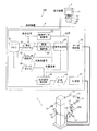
まず、図1および図2を参照して、本発明の第1実施形態によるロボットシステム100の構成について説明する。なお、ロボットシステム100は、本発明の「ロボット制御装置」の一例である。
(First embodiment)
First, the configuration of the
図1に示すように、ロボットシステム100は、双腕ロボット1と、双腕ロボット1を制御する制御装置2と、制御装置2に接続される教示装置(教示入力部)3とを備えている。
As shown in FIG. 1, the
双腕ロボット1には、左アーム11と右アーム12とが設けられている。なお、左アーム11と右アーム12とは、本発明の「アーム」の一例である。左アーム11と右アーム12とには、それぞれ、複数の関節13が設けられている。また、複数の関節13は、図示しないモータによって駆動されるように構成されている。また、左アーム11の先端には、左グリッパ14が設けられている。また、右アーム12の先端には、右グリッパ15が設けられている。なお、右グリッパ15は、本発明の「エンドエフェクタ」の一例である。また、双腕ロボット1は、後述するコネクタなどのワーク200を把持するように構成されている。また、右グリッパ15には、1つのカメラ16が搭載されている。そして、右アーム12の移動に伴って、カメラ16の撮影位置が移動するように構成されている。また、カメラ16は、2つの撮影位置からワーク200を撮影することにより、2つの画像からなるステレオ画像を撮影するように構成されている。なお、後述するように、この2つの画像から、ワーク200の3次元の位置姿勢情報が得られる。
The
制御装置2には、不揮発性メモリなどからなるメモリ21と、教示データ記憶部22と、動作プログラム解析部23と、指令生成部24と、サーボ制御部25と、位置姿勢検出部26と、計測部27とが設けられている。なお、メモリ21は、本発明の「記憶部」の一例である。動作プログラム解析部23は、メモリ21に接続されているとともに、指令生成部24に接続されている。メモリ21には、動作プログラム31が格納されているとともに、ステレオ視条件32とワークモデル34も格納されている。また、動作プログラム解析部23は、メモリ21から動作プログラム31を読み出すように構成されている。また、動作プログラム解析部23は、ロボットの動作が記述された動作プログラム31を解析して必要な処理を呼び出す機能を有する。また、指令生成部24は、メモリ21に接続されているとともに、メモリ21からステレオ視条件32を読み出すように構成されている。また、指令生成部24は、サーボ制御部25に接続されているとともに、サーボ制御部25は、双腕ロボット1に接続されている。
The control device 2 includes a
また、教示データ記憶部22は、メモリ21に接続されているとともに、メモリ21に記憶されている動作プログラム31に双腕ロボット1の現在の位置を教示位置として書き込む(組み込む)機能を有する。なお、教示位置は、後述するように、ユーザが教示動作時に教示装置3の所定のキーを押下することにより、動作プログラム31に書き込まれるように構成されている。また、教示データ記憶部22は、指令生成部24に接続されている。また、位置姿勢検出部26は、指令生成部24と計測部27とに接続されている。また、位置姿勢検出部26は、計測部27との間で計測データ33をやり取りするように構成されている。また、計測部27は、双腕ロボット1の右グリッパ15に搭載されるカメラ16に接続されている。なお、動作プログラム31、ステレオ視条件32およびワークモデル34は、図示しないハードディスクに記憶されていてもよい。なお、教示装置3は、本発明の「教示入力部」の一例である。
The teaching
計測部27は、双腕ロボット1の右グリッパ15に搭載されるカメラ16からワーク200のステレオ画像を取得するとともに計測データ33として出力する機能を有する。位置姿勢検出部26は、ワークモデル34および計測データ33から、ワーク200の3次元の位置姿勢情報を算出する機能を有する。なお、ワークモデル34とは、CADデータなどのワーク200の3次元形状データである。また、位置姿勢検出部26は、算出したワーク200の位置姿勢情報を、指令生成部24に出力する機能を有する。
The
指令生成部24は、ユーザによる教示装置3の操作(教示データ)に従って移動する双腕ロボット1(右アーム12や左アーム11など)の移動の軌道を生成する機能を有する。また、指令生成部24は、ステレオ視条件32、計測されたワーク200の位置姿勢情報に基づいて、右グリッパ15のワーク200の把持動作や、カメラ16によるワーク200の撮影動作を行うための双腕ロボット1の移動の軌道を生成する。なお、第1実施形態では、ステレオ視条件32は、ワーク200とカメラ16との間の距離(撮影距離L、図11参照)と、カメラ16がステレオ画像を撮影するための2つの撮影位置の間隔(ステレオ視間隔W、図11参照)とを含む。サーボ制御部25は、指令生成部24によって生成された双腕ロボット1の移動の軌道に従って、右アーム12や左アーム11に設けられる図示しないモータを駆動する機能を有する。
The
教示装置3は、制御装置2(指令生成部24)に接続されている。また、教示装置3は、双腕ロボット1の移動を教示するとともに、操作する機能を有する。また、教示装置3には、表示部41が設けられている。また、教示装置3には、表示部41にメニューを表示させるメニューキー42、表示部41に表示されるボタンを選択する選択キー43、双腕ロボット1に対する指令を決定する決定キー44、双腕ロボット1を移動させる移動キー45などの複数のキーが設けられている。
The teaching device 3 is connected to the control device 2 (command generation unit 24). The teaching device 3 has a function of teaching and operating the movement of the double-
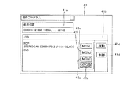
また、図2に示すように、教示装置3の表示部41は、双腕ロボット1の教示位置を表す教示位置画面41aや、双腕ロボット1を動作させるプログラムが表示されるJOB画面41bが表示されるように構成されている。また、JOB画面41bには、移動ボタン41cや制御ボタン41dなど、JOBのコマンドが分類されたボタンが表示されるように構成されている。また、JOB画面41bには、双腕ロボット1の移動を指令する移動コマンドを登録するための直線補間ボタン(MOVL)41e、リンク補間ボタン(MOVJ)41f、および、円弧補間ボタン(MOVC)41gなどが表示されるように構成されている。なお、直線補間は、「補助情報」として双腕ロボット1のアーム先端が直線的に動く指令を含んでいる。また、リンク補間ボタン41fは、「補助情報」として双腕ロボット1のアームの関節13が個々に駆動して、アームが所定の位置まで最短の時間で移動する指令を含んでいる。また、円弧補間ボタン41gは、「補助情報」として双腕ロボット1のアーム先端が円弧状に動く指令を含んでいる。また、JOB画面41bには、半自動教示コマンドとしてカメラ16によってワーク200のステレオ画像の撮影を指令するステレオ視コマンドを登録するためのSCAMボタン41hが表示されるように構成されている。なお、アーム先端が直線的に動く指令、アームが所定の位置まで最短の時間で移動する指令、アーム先端が円弧状に動く指令、および、ワーク200のステレオ画像の撮影をする指令は、本発明の「コマンド情報」の一例である。
As shown in FIG. 2, the
次に、図3〜図9を参照して、ロボットシステム100の教示動作について説明する。なお、第1実施形態では、双腕ロボット1が把持するワーク200は、図4に示すように、ケース201から延びる複数のリード線202に接続されるコネクタである。また、図4は、テーブル上に治具や供給装置によって位置が固定されたケース201を、予め教示された指令に基づいて、左グリッパ14がケース201を把持して持ち上げた状態を示している。なお、リード線202は、柔軟な素材で構成されており、リード線202に接続されたワーク200(コネクタ)の位置は固定されていない。
Next, the teaching operation of the
まず、第1実施形態では、右グリッパ15がワーク200を把持する把持位置に対するカメラ16の撮影位置(ステレオ視条件32)がユーザの入力操作に基づいて予めメモリ21に記憶されている。次に、図3のステップS1において、教示装置3の移動キー(ジョグ)45がユーザにより操作されることにより、図7に示すように、ワーク(コネクタ)200を把持する把持位置に右グリッパ15が移動する。これにより、双腕ロボット1が移動する軌道が制御装置2の指令生成部24により生成される。
First, in the first embodiment, the photographing position (stereo viewing condition 32) of the
次に、教示装置3のメニューキー42がユーザにより押下される。これにより、ステップS2において、図5に示すように、教示装置3の表示部41のJOB画面41bには、移動ボタン41cと制御ボタン41dなどのボタンが表示される。次に、図6に示すように、ユーザにより教示装置3の選択キー43が押下されて移動ボタン41cが選択された後、決定キー44が押下されることにより、直線補間ボタン41e、リンク補間ボタン41f、円弧補間ボタン41g、および、SCAMボタン41hが表示される。
Next, the
次に、第1実施形態では、ステップS3において、図8に示すように、右グリッパ15がワーク200を把持する把持位置に位置する状態で、ユーザにより教示装置3の選択キー43および決定キー44が押下されて、SCAMボタン41hが選択および決定されることにより、カメラ16がワーク200のステレオ画像を撮影する指令(ステレオ視コマンド、STEREOCAM)が動作プログラム31に登録されて組み込まれる。なお、ステレオ視コマンド(STEREOCAM)は、本発明の「撮影指令コマンド」の一例である。また、双腕ロボット1の現在位置(右グリッパ15がワーク200を把持する把持位置)が、教示位置データとしてメモリ21に保存される。なお、教示位置データは、教示位置番号(C00001)として保存される。
Next, in the first embodiment, in step S3, as shown in FIG. 8, the user selects the
また、第1実施形態では、ステレオ視コマンドは、補助情報として教示位置番号(C00001)、ワーク200の位置姿勢情報(P012)、ステレオ画像の撮影動作における双腕ロボット1の移動速度(V=10.0)、および、ワーク200を特定する対象物番号(OBJ#(1))と関連付けられて動作プログラム31に登録されて組み込まれる。なお、ワーク200の位置姿勢情報(P012)は、後述する再生動作のステップS13において位置姿勢情報が算出された後、上書きされるように構成されており、ステレオ視コマンドが登録される時点では、デフォルトの値が入力されている。また、動作プログラム31に登録された移動速度と対象物番号とは、変更することが可能である。なお、後述するように、予めメモリ21に記憶されているカメラ16の撮影位置(ステレオ視条件32)に基づいてステレオ視コマンド(カメラ16によるワーク200の撮影)が実行されるので、カメラ16を撮影位置に移動させるための双腕ロボット1の移動を教示する必要はない。
In the first embodiment, the stereo view command includes the teaching position number (C00001) as auxiliary information, the position and orientation information (P012) of the
次に、ステップS4において、図9に示すように、第1実施形態では、右グリッパ15がワーク200を把持する把持位置に位置する状態で、ユーザにより、教示装置3の選択キー43および決定キー44が押下されて、たとえば直線補間ボタン41eが選択および決定されることにより、移動コマンド(直線補間)が動作プログラム31に登録されて組み込まれる。なお、移動コマンド(直線補間)は、本発明の「移動指令コマンド」の一例である。また、移動コマンド(直線補間)は、ワーク200の位置変数(P012)および移動速度(V=10.0)と関連付けられて、動作プログラム31に登録される。
Next, in step S4, as shown in FIG. 9, in the first embodiment, the user selects the
次に、図10および図11を参照して、ロボットシステム100の再生動作について説明する。なお、再生動作とは、上記ステップS1〜ステップS4において教示された動作(動作プログラム31)に基づくロボットシステム100の動作を意味する。
Next, the reproduction operation of the
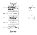
まず、ステップS11において、動作プログラム解析部23によって、メモリ21から動作プログラム31とステレオ視条件32とが読み出される。そして、動作プログラム31の中に登録されているステレオ視コマンド(STEREOCAM)の実行が動作プログラム解析部23により指令生成部24に指令される。指令生成部24では、ステレオ視コマンドとともに登録された教示位置(教示位置番号C00001)と、ステレオ視条件32とに基づいて、カメラ16の撮影位置までの双腕ロボット1の軌道が生成される。そして、生成された軌道に基づいて、サーボ制御部25がモータを駆動することにより、双腕ロボット1(右アーム12)が移動される。
First, in step S <b> 11, the operation
具体的には、カメラ16から撮影距離L離れた位置を原点とする座標系A1(図4参照)を、右グリッパ15がワーク200を把持した状態の把持位置を原点とする座標系A2(図7参照)に合わせるように右アーム12の移動量(軌道)が指令生成部24により算出される。つまり、図11に示すように、カメラ16がワーク200(コネクタ)から撮影距離L離れた位置(位置B1)に移動する移動量(軌道)が算出される。次に、位置B1から矢印X1方向にステレオ視間隔Wの1/2の距離移動した位置(位置B2)までの移動量(軌道)が算出される。なお、ステレオ視間隔Wは、ステレオ視条件32として予めメモリ21に記憶されている。このように算出された移動量(軌道)に基づいて、右アーム12が位置B2に移動した後、ワーク200がカメラ16により撮影される。
Specifically, a coordinate system A1 (see FIG. 4) having the origin at a position away from the
さらに、カメラ16がワーク200を撮影した位置B2から矢印X2方向にステレオ視間隔W移動した位置(位置B3)までの移動量(軌道)が算出される。そして、算出された移動量(軌道)に基づいて、右アーム12が位置B3に移動した後、ワーク200がカメラ16により再び撮影される。このように、2つの異なる位置(位置B2および位置B3)においてカメラ16によりワーク200が撮影されることにより、ワーク200のステレオ画像が得られる。次に、ステップS12において、撮影されたステレオ画像を計測データ33として位置姿勢検出部26へ出力する。
Further, a movement amount (orbit) from the position B2 where the
次に、ステップS13において、右アーム12が把持しようとしているワーク(コネクタ)200に対応するワークモデル34(CADデータなどのコネクタの3次元形状データ)が位置姿勢検出部26により読み出される。そして、ステップS12において出力された計測データ33と、メモリ21に記憶されているワークモデル34とが位置姿勢検出部26により比較され、ワーク200の位置姿勢情報が求められる。そして、ステップS14において、位置姿勢情報は、位置変数として指令生成部24に出力される。なお、位置変数は、X、Y、Z、Roll、Pitch、Yawの成分からなる。
Next, in step S <b> 13, the position /
次に、ステップS15において、動作プログラム31に登録されている移動コマンド(直線補間)の実行が、動作プログラム解析部23により指令生成部24に指令される。これにより、動作プログラム31の移動コマンドに指定された位置変数(上記ステップS14において指令生成部24に出力された位置変数)に基づいて、ワーク200を把持する把持位置への軌道が、指令生成部24により生成される。そして、生成された軌道に基づいて、モータがサーボ制御部25により駆動されることにより、右アーム12の右グリッパ15がワーク200を把持する把持位置に移動する。
Next, in step S <b> 15, execution of the movement command (linear interpolation) registered in the
第1実施形態では、上記のように、右グリッパ15がワーク200を把持する把持位置に対するカメラ16の撮影位置の情報(ステレオ視条件32)が予め記憶されているメモリ21と、ユーザによる撮影動作の教示時に、ユーザにより、右グリッパ15がワーク200を把持する把持位置に移動された状態で、把持位置を教示位置データとするユーザによるステレオ視コマンドの登録を受け付け可能な教示装置3とを設ける。これにより、右グリッパ15がワーク200を把持する把持位置に移動された状態で登録されたステレオ視コマンドにより、把持位置に対するカメラ16の撮影位置の情報に基づいて、カメラ16の撮影位置までの移動を行わせることができる。その結果、ユーザがカメラ16の画像が表示される表示部を見ながらワーク200を撮影する位置にカメラ16を移動させてから、ステレオ視コマンドが登録される場合と異なり、カメラ16の撮影位置に移動させる動作を教示しなくてもよい分、撮影動作の教示操作が煩雑になるのを抑制することができる。
In the first embodiment, as described above, the
また、第1実施形態では、上記のように、ステレオ視コマンドを、把持位置からなる教示位置データと関連付けて登録することによって、ワーク200の撮影位置を教示しなくても、把持位置と、予めメモリ21に記憶されているステレオ視条件32(右グリッパ15がワーク200を把持する把持位置に対するカメラ16の撮影位置の情報であり、把持位置に対する距離と方向の情報を含む)とに基づいて、カメラ16によるワーク200の撮影動作を行わせることができる。
Further, in the first embodiment, as described above, the stereo view command is registered in association with the teaching position data including the gripping position, so that the gripping position can be obtained in advance without teaching the shooting position of the
また、第1実施形態では、上記のように、把持位置からなる教示位置データに加えて、ワーク200の位置姿勢情報(P012)と、双腕ロボット1の移動速度(V=10.0)と、ワーク200を特定する対象物番号(OBJ#(1))とを関連付けてステレオ視コマンドを登録する。これにより、教示位置データ、位置姿勢情報、移動速度および対象物番号が対応付けられた1行のステレオ視コマンドによってワーク200の撮影動作が教示されるので、教示位置データ、位置姿勢情報、移動速度および対象物番号などを個別に登録する場合と異なり、撮影動作の教示の手間を省くことができる。これにより、撮影動作の教示が煩雑になるのをより抑制することができる。
In the first embodiment, as described above, in addition to the teaching position data including the gripping position, the position and orientation information (P012) of the
また、第1実施形態では、上記のように、ステレオ視コマンドを、動作プログラム31に登録して組み込むように構成する。これにより、容易に、双腕ロボット1の再生動作に撮影動作を組み込むことができる。
In the first embodiment, as described above, the stereo viewing command is registered in the
また、第1実施形態では、上記のように、再生動作時に、教示装置3により登録が受け付けられたステレオ視コマンドと、メモリ21に予め記憶されている把持位置に対するカメラ16の撮影位置の情報とに基づいて、カメラ16の撮影位置への移動と、カメラ16によるワーク200の撮影とを行うように構成する。これにより、カメラ16の撮影位置への移動を教示することなく、ワーク200の撮影が行われるので、撮影動作の教示を容易に行うことができる。
Further, in the first embodiment, as described above, during the reproduction operation, the stereo viewing command received by the teaching device 3 and information on the shooting position of the
また、第1実施形態では、上記のように、教示装置3は、ユーザによる教示時に、ユーザにより、右グリッパ15がワーク200を把持する把持位置に移動された状態で、ステレオ視コマンドに加えて把持位置への移動コマンド(直線補間)を登録するように構成する。これにより、撮影動作の教示に続けて把持動作の教示を容易に行うことができる。
Further, in the first embodiment, as described above, the teaching device 3 can be used in addition to the stereo viewing command in a state where the
また、第1実施形態では、上記のように、再生動作時に、教示装置3により登録が受け付けられたステレオ視コマンドと、メモリ21に予め記憶されている把持位置に対するカメラ16の撮影位置の情報とに基づいて、カメラ16の撮影位置への移動と、カメラ16によるワーク200の撮影とが行われた後、計測結果に従って修正された把持位置への移動コマンド(直線補間)に基づいて、カメラ16の撮影位置からワーク200の把持位置への移動が行われるように構成する。これにより、ステレオ視コマンドと移動コマンドとの2つのコマンドによって、カメラ16の2箇所の撮影位置への移動と、2箇所での撮影と、把持位置への移動との5つの動作が行われるので、カメラ16の2箇所の撮影位置への移動と、2箇所での撮影と、把持位置への移動との5つの動作をそれぞれコマンド(合計5つのコマンド)により行う場合と異なり、撮影動作および移動動作の教示を容易に行うことができる。
Further, in the first embodiment, as described above, during the reproduction operation, the stereo viewing command received by the teaching device 3 and information on the shooting position of the
また、第1実施形態では、上記のように、メモリ21に予め記憶されている把持位置に対するカメラ16の撮影位置の情報に、ワーク200とカメラ16との間の撮影距離Lを含めるように構成する。これにより、ワーク200とカメラ16との間の撮影距離Lが予め記憶されているので、撮影動作の教示の際に、ワーク200とカメラ16との間の撮影距離Lを教示する必要がない分、撮影動作の教示を容易に行うことができる。
In the first embodiment, as described above, the shooting distance L between the
(第2実施形態)
次に、図12〜図16を参照して、第2実施形態のロボットシステム101について説明する。この第2実施形態では、上記ワーク200の3次元の位置姿勢情報を算出するための撮影動作の教示と、教示された撮影動作に基づく再生動作とについて説明した第1実施形態と異なり、ワーク200の3次元モデルを登録する際の撮影動作の教示について説明する。なお、ロボットシステム101は、本発明の「ロボット制御装置」の一例である。
(Second Embodiment)
Next, a
図12に示すように、第2実施形態のロボットシステム101は、双腕ロボット111と、双腕ロボット111を制御する制御装置112と、制御装置112に接続される教示装置113とを備えている。なお、教示装置113は、本発明の「教示入力部」の一例である。
As shown in FIG. 12, the
双腕ロボット111の右グリッパ15には、2つのカメラからなるステレオカメラ114が搭載されている。なお、ステレオカメラ114は、本発明の「カメラ」の一例である。そして、右アーム12の移動に伴って、ステレオカメラ114の撮影位置が移動するように構成されている。また、ステレオカメラ114は、複数の撮影位置からワーク200を撮影することにより、複数のステレオ画像を撮影するように構成されている。なお、後述するように、この複数のステレオ画像から、ワーク200の3次元画像が得られる。また、双腕ロボット111のその他の構成は、上記第1実施形態と同様である。
A
また、制御装置112には、モデル計測動作実行部115と、3次元モデル生成部116とが設けられている。モデル計測動作実行部115は、メモリ21に接続されるとともに、メモリ21からモデル計測条件117を読み出すように構成されている。ここで、第2実施形態では、モデル計測条件117は、ワーク200とステレオカメラ114との間の距離(撮影距離L、図16参照)と、ステレオカメラ114の視点(撮影位置)を変えるための回転角度とを含む。
Further, the
また、モデル計測動作実行部115は、指令生成部24に接続されている。また、3次元モデル生成部116は、メモリ21に接続されるとともに、メモリ21にワークモデル34を書き込むように構成されている。また、3次元モデル生成部116は、計測部27に接続されているとともに、計測部27との間で計測データ33のやり取りを行うように構成されている。また、3次元モデル生成部116は、教示装置113に接続されている。また、制御装置112のメモリ21には、モデル計測条件117が記憶されている。
The model measurement
また、モデル計測動作実行部115は、後述する教示装置113の表示部113aに表示されるモデル登録画面113bにおいて、ユーザによりモデル計測が指令されると、モデル計測条件117に基づいて、現在の右グリッパ15の位置を基準として、複数の計測位置を自動的に決めるとともに、指令生成部24に複数の計測位置への移動を指令する機能を有する。また、3次元モデル生成部116は、計測部27が取得した複数組の計測データ33(複数のステレオ画像)を合成して、ワーク200の3次元画像を作成するとともに、作成した3次元画像をワークモデル34としてメモリ21に保存する機能を有する。
In addition, when a model measurement is instructed by the user on the
また、図13に示すように、教示装置113の表示部113aは、モデル登録画面113bが表示されるように構成されている。モデル登録画面113bには、ワーク200の3次元画像を取得するためのデータ取得ボタン113c、ワーク200の対象物番号が入力される対象物番号入力欄113d、および、ワーク200の3次元画像を登録するための登録ボタン113eが表示されるように構成されている。なお、第2実施形態のその他の構成は、上記第1実施形態と同様である。
As shown in FIG. 13, the
次に、図14〜図16を参照して、ロボットシステム101のモデル登録操作について説明する。
Next, a model registration operation of the
図14に示すように、ステップS21において、教示装置113の移動キー45(ジョグ)がユーザにより操作されることにより、双腕ロボット111が移動する軌道が制御装置112の指令生成部24により生成される。これにより、図15に示すように、ワーク200(コネクタ)を把持する把持位置に右グリッパ15が移動する。
As shown in FIG. 14, in step S <b> 21, when the movement key 45 (jog) of the
次に、ステップS22において、モデル登録画面113bにおいて、データ取得ボタン113cがユーザにより選択、決定される。これにより、ステップS23において、メモリ21からモデル計測条件117がモデル計測動作実行部115により読み出される。そして、現在の右グリッパ15の位置とモデル計測条件117とに基づいて、第1計測位置(位置C1、図16参照)への移動が、モデル計測動作実行部115により指令生成部24に指令される。これにより、指令生成部24では、第1計測位置(位置C1)へ双腕ロボット111が移動するための軌道が生成される。そして、図16に示すように、生成された軌道に基づいて、サーボ制御部25がモータを駆動することにより、双腕ロボット111(右アーム12)が第1計測位置(位置C1)に移動する。具体的には、ステレオカメラ114は、ワーク200から撮影距離L離れた位置に位置するように配置される。その後、ワーク200(コネクタ)のステレオ画像(第1計測データ33a)が、ステレオカメラ114によって撮影される。
Next, in step S22, the
次に、ステップS24において、モデル計測条件117に基づいて、第2計測位置(位置C2)への移動が、モデル計測動作実行部115により指令生成部24に指令される。これにより、指令生成部24では、第2計測位置(位置C2)へ双腕ロボット111が移動するための軌道が生成される。そして、図16に示すように、生成された軌道に基づいて、サーボ制御部25がモータを駆動することにより、双腕ロボット111(右アーム12)が第2計測位置(位置C2)に移動する。具体的には、ステレオカメラ114は、ワーク200を中心として第1計測位置(位置C1)から約90度回転した位置で、かつ、ワーク200から撮影距離L離れた位置に位置するように配置される。その後、ワーク200(コネクタ)のステレオ画像(第2計測データ33b)が、ステレオカメラ114によって撮影される。
Next, in step S <b> 24, based on the
次に、ステップS25において、第1計測データ33aと、第2計測データ33bとを合成することにより、ワーク200の3次元の構造がワークモデル34として3次元モデル生成部116により生成される。その後、ワークモデル34の画像113f(図13参照)が、教示装置113の表示部113aに表示される。
Next, in step S25, the three-dimensional structure of the
次に、ステップS26において、表示部113aのモデル登録画面113bにおいて、対象物番号入力欄113dに対象物(ワーク200)の番号がユーザにより入力されるとともに、登録ボタン113eがユーザにより選択、決定される。これにより、ステップS27において、ワークモデル34がメモリ21に保存される。
Next, in step S26, on the
なお、第2実施形態の効果は、上記第1実施形態と同様である。 The effect of the second embodiment is the same as that of the first embodiment.
なお、今回開示された実施形態は、すべての点で例示であって制限的なものではないと考えられるべきである。本発明の範囲は、上記した実施形態の説明ではなく特許請求の範囲によって示され、さらに特許請求の範囲と均等の意味および範囲内でのすべての変更が含まれる。 The embodiment disclosed this time should be considered as illustrative in all points and not restrictive. The scope of the present invention is shown not by the above description of the embodiments but by the scope of claims for patent, and further includes all modifications within the meaning and scope equivalent to the scope of claims for patent.
たとえば、上記第1および第2実施形態では、双腕ロボットの右グリッパにカメラが搭載される例を示したが、本発明はこれに限られない。たとえば、双腕ロボットの左グリッパにカメラを搭載してもよいし、双腕ロボットのグリッパではなくアームにカメラを搭載してもよい。 For example, in the first and second embodiments, the camera is mounted on the right gripper of the double-arm robot, but the present invention is not limited to this. For example, the camera may be mounted on the left gripper of the double-arm robot, or the camera may be mounted on the arm instead of the gripper of the double-arm robot.
また、上記第1および第2実施形態では、把持位置からなる教示位置データに加えて、ワークの位置姿勢情報と、双腕ロボットの移動速度と、ワークを特定する対象物番号とを関連付けてステレオ視コマンドを登録する例を示したが、本発明はこれに限られない。本発明では、把持位置からなる教示位置データに加えて、ワークの位置姿勢情報、双腕ロボットの移動速度およびワークを特定する対象物番号のうちの少なくとも1つがステレオ視コマンドに関連付けられていてもよい。 In the first and second embodiments, in addition to the teaching position data including the gripping position, the position and orientation information of the workpiece, the moving speed of the double-arm robot, and the object number for specifying the workpiece are associated with each other in stereo. Although an example in which a visual command is registered has been shown, the present invention is not limited to this. In the present invention, in addition to the teaching position data including the gripping position, at least one of the position / posture information of the workpiece, the moving speed of the two-arm robot, and the object number for specifying the workpiece may be associated with the stereo vision command. Good.
また、上記第1および第2実施形態では、カメラがワークのステレオ画像を撮影する例を示したが、本発明はこれに限られない。たとえば、カメラがワークのステレオ画像以外の画像を撮影するようにしてもよい。 In the first and second embodiments, an example in which the camera captures a stereo image of a work has been described. However, the present invention is not limited to this. For example, the camera may capture an image other than a stereo image of the work.
また、上記第1および第2実施形態では、双腕ロボットの右グリッパがワークを把持する例を示したが、本発明はこれに限られない。たとえば、双腕ロボットの左グリッパがワークを把持するようにしてもよい。この場合、カメラは、左グリッパに搭載される。 In the first and second embodiments, the right gripper of the double-arm robot holds the workpiece. However, the present invention is not limited to this. For example, the left gripper of the double-arm robot may hold the workpiece. In this case, the camera is mounted on the left gripper.
また、上記第1実施形態では、双腕ロボットに1つのカメラが搭載される例を示したが、本発明はこれに限られない。たとえば、双腕ロボットに2つのカメラからなるステレオカメラを搭載して、ステレオ画像を撮影するようにしてもよい。 In the first embodiment, the example in which one camera is mounted on the double-arm robot is shown, but the present invention is not limited to this. For example, a stereo camera composed of two cameras may be mounted on the double-arm robot to capture a stereo image.
また、上記第2実施形態では、双腕ロボットに2つのカメラからなるステレオカメラが搭載される例を示したが、本発明はこれに限られない。たとえば、第1実施形態と同様に双腕ロボットに1つのカメラを搭載し、撮影位置を異ならせて1つのカメラによって2つの画像を撮影してステレオ画像を得るようにしてもよい。 In the second embodiment, an example in which a stereo camera composed of two cameras is mounted on a dual-arm robot has been described. However, the present invention is not limited to this. For example, as in the first embodiment, one camera may be mounted on the double-arm robot, and two images may be taken by one camera at different shooting positions to obtain a stereo image.
また、上記第1および第2実施形態では、半自動教示コマンドの態様についても実施形態のように「撮影指令コマンド」に関するものに限定されることはなく、適宜の半自動教示コマンドを設定可能である。たとえば、位置が既知のA地点からB地点に物体を搬送する際には、A地点のみを教示位置とし、半自動教示コマンドを設定することで、A地点の位置に基づいて、A地点からB地点に物体を搬送するようにロボットを動作させるような構成としてもよい。 In the first and second embodiments, the mode of the semi-automatic teaching command is not limited to that relating to the “shooting command” as in the embodiment, and an appropriate semi-automatic teaching command can be set. For example, when an object is transported from a point A to a point B with a known position, only the point A is set as a teaching position, and a semi-automatic teaching command is set. The robot may be configured to operate so as to convey the object.
3、113 教示装置(教示入力部)
11 左アーム(アーム)
12 右アーム(アーム)
15 右グリッパ(エンドエフェクタ)
16 カメラ
21 メモリ(記憶部)
24 指令生成部
31 動作プログラム
100、101 ロボットシステム(ロボット制御装置)
114 ステレオカメラ(カメラ)
200 ワーク
3, 113 Teaching device (Teaching input unit)
11 Left arm (arm)
12 Right arm (arm)
15 Right gripper (end effector)
16
24
114 Stereo camera (camera)
200 works
Claims (9)
教示位置の入力と、少なくとも前記教示位置に対応付けられるコマンド情報の選択とを受け付けて前記教示位置と前記コマンド情報とを組み合わせた教示データを作成する教示入力部と、
前記教示データに基づいて動作指令を生成する指令生成部とを備え、
前記教示入力部により選択される前記コマンド情報は、前記教示位置と、予め設定された前記教示位置に基づく補助的な動作を前記ロボットに動作させるための、前記教示位置に対する補助的動作位置の情報を含む補助情報とに対応付けられたコマンド情報を含み、
前記ロボットは、ワークを把持するエンドエフェクタと、前記ワークを撮影するためのカメラとを含み、
前記コマンド情報は、前記エンドエフェクタが前記ワークを把持する前記教示位置としての把持位置と、前記把持位置に対する前記カメラの撮影位置の情報からなる前記補助情報とに対応付けられた撮影指令コマンドを含み、
前記教示入力部は、ユーザによる教示時に、前記ユーザにより、前記エンドエフェクタが前記ワークを把持する把持位置に移動された状態で、前記撮影指令コマンドに加えて前記把持位置への移動指令コマンドを登録可能に構成されている、ロボット制御装置。 A robot control device for controlling a robot,
A teaching input unit that accepts input of a teaching position and selection of command information associated with at least the teaching position, and generates teaching data combining the teaching position and the command information;
A command generation unit that generates an operation command based on the teaching data,
The command information selected by the teaching input unit is information on an auxiliary operation position with respect to the teaching position for causing the robot to perform an auxiliary operation based on the teaching position and the preset teaching position. only contains the command information associated with the auxiliary information, including,
The robot includes an end effector for gripping a workpiece, and a camera for photographing the workpiece,
The command information includes a shooting command command associated with a gripping position as the teaching position at which the end effector grips the workpiece and the auxiliary information including information on a shooting position of the camera with respect to the gripping position. ,
The teaching input unit registers a movement command command to the gripping position in addition to the photographing command command in a state where the end effector is moved to a gripping position for gripping the workpiece by the user at the time of teaching by the user. A robot controller that can be configured .
複数の駆動関節を有するアームとを備え、
前記ロボット制御装置は、前記駆動関節の動作を制御するように構成されている、ロボット。 The robot controller according to any one of claims 1 to 6 ,
An arm having a plurality of drive joints,
The robot control device is configured to control an operation of the drive joint.
ロボットに取り付けられた前記エンドエフェクタが前記ワークを把持する前記把持位置に移動された状態で、前記ユーザの教示操作に基づいて、前記把持位置を教示位置として記憶させるステップと、
前記エンドエフェクタが前記ワークを把持する前記把持位置に移動された状態で、前記ユーザの教示操作に基づいて、再生動作時に前記補助情報を用いて前記ロボットを前記教示位置としての前記把持位置から前記撮影位置に移動して撮影する動作をさせる撮影指令コマンドを前記把持位置としての前記教示位置と関連付けて入力させるステップと、
前記エンドエフェクタが前記ワークを把持する前記把持位置に移動された状態で、前記把持位置への移動を指令する移動指令コマンドを入力させるステップとを備える、ロボット制御装置の教示方法。 Storing, as auxiliary information, information on the photographing position of the camera with respect to the gripping position at which the end effector grips the workpiece based on the teaching operation of the user;
Storing the gripping position as a teaching position based on a teaching operation of the user in a state where the end effector attached to the robot is moved to the gripping position for gripping the workpiece;
In a state where the end effector is moved to the gripping position for gripping the workpiece, based on the teaching operation of the user, the robot is moved from the gripping position as the teaching position using the auxiliary information during the reproduction operation. A step of inputting a shooting command command for moving to a shooting position and performing a shooting operation in association with the teaching position as the gripping position ;
A method for teaching a robot control device, comprising: inputting a movement command command for instructing movement to the gripping position in a state where the end effector is moved to the gripping position for gripping the workpiece .
Priority Applications (1)
| Application Number | Priority Date | Filing Date | Title |
|---|---|---|---|
| JP2010223362A JP5556552B2 (en) | 2010-10-01 | 2010-10-01 | Robot control device, robot, and teaching method of robot control device |
Applications Claiming Priority (1)
| Application Number | Priority Date | Filing Date | Title |
|---|---|---|---|
| JP2010223362A JP5556552B2 (en) | 2010-10-01 | 2010-10-01 | Robot control device, robot, and teaching method of robot control device |
Publications (2)
| Publication Number | Publication Date |
|---|---|
| JP2012076181A JP2012076181A (en) | 2012-04-19 |
| JP5556552B2 true JP5556552B2 (en) | 2014-07-23 |
Family
ID=46237015
Family Applications (1)
| Application Number | Title | Priority Date | Filing Date |
|---|---|---|---|
| JP2010223362A Expired - Fee Related JP5556552B2 (en) | 2010-10-01 | 2010-10-01 | Robot control device, robot, and teaching method of robot control device |
Country Status (1)
| Country | Link |
|---|---|
| JP (1) | JP5556552B2 (en) |
Cited By (1)
| Publication number | Priority date | Publication date | Assignee | Title |
|---|---|---|---|---|
| CN112207835A (en) * | 2020-09-18 | 2021-01-12 | 浙江大学 | A method based on teaching and learning to realize the task of dual-arm cooperative operation |
Families Citing this family (8)
| Publication number | Priority date | Publication date | Assignee | Title |
|---|---|---|---|---|
| JP6660962B2 (en) * | 2015-11-18 | 2020-03-11 | 株式会社Fuji | Teaching device and control information generation method |
| CN107717983A (en) * | 2017-08-21 | 2018-02-23 | 北京精密机电控制设备研究所 | A kind of apery mechanical arm teaching control method |
| JP6773098B2 (en) * | 2018-10-17 | 2020-10-21 | 株式会社安川電機 | Robot system and robot control method |
| JP2021096081A (en) * | 2019-12-13 | 2021-06-24 | 倉敷紡績株式会社 | Three-dimensional connector measurement method, connector gripping position calculation method, connector gripping method, connector connection method, and connector |
| CN115003464B (en) * | 2020-02-12 | 2025-09-05 | 发那科株式会社 | Robotic system |
| JP2021179933A (en) * | 2020-05-15 | 2021-11-18 | 株式会社リコー | Communication terminal, communication system, communication method, and program |
| JP7459253B2 (en) * | 2020-06-19 | 2024-04-01 | 川崎重工業株式会社 | Imaging system, robot system, and imaging system control method |
| CN115916480B (en) * | 2020-06-23 | 2026-01-02 | 川崎重工业株式会社 | Robot teaching methods and robot operation methods |
Family Cites Families (4)
| Publication number | Priority date | Publication date | Assignee | Title |
|---|---|---|---|---|
| JPH06226664A (en) * | 1993-01-27 | 1994-08-16 | Mitsubishi Heavy Ind Ltd | Robot teaching device |
| JP2005138223A (en) * | 2003-11-06 | 2005-06-02 | Fanuc Ltd | Positional data correcting device for robot |
| JP2006346790A (en) * | 2005-06-15 | 2006-12-28 | Toyota Motor Corp | Robot, interference discrimination method and interference discrimination device |
| JP2008009899A (en) * | 2006-06-30 | 2008-01-17 | Olympus Corp | Automatic teaching system and method for assembly work robot |
-
2010
- 2010-10-01 JP JP2010223362A patent/JP5556552B2/en not_active Expired - Fee Related
Cited By (1)
| Publication number | Priority date | Publication date | Assignee | Title |
|---|---|---|---|---|
| CN112207835A (en) * | 2020-09-18 | 2021-01-12 | 浙江大学 | A method based on teaching and learning to realize the task of dual-arm cooperative operation |
Also Published As
| Publication number | Publication date |
|---|---|
| JP2012076181A (en) | 2012-04-19 |
Similar Documents
| Publication | Publication Date | Title |
|---|---|---|
| JP5556552B2 (en) | Robot control device, robot, and teaching method of robot control device | |
| JP6763846B2 (en) | Teaching device and teaching method for teaching robots | |
| CN105666505B (en) | Robot system having display for augmented reality | |
| KR100762380B1 (en) | Motion control apparatus for teaching robot position, robot-position teaching apparatus, motion control method for teaching robot position, robot-position teaching method, and motion control program for teaching robot-position | |
| JP6843051B2 (en) | Remote control robot system | |
| JP6420229B2 (en) | A robot system including a video display device that superimposes and displays an image of a virtual object on a video of a robot | |
| JP7190552B1 (en) | Robot teaching system | |
| CN104942803B (en) | Robot controller, robot, robot system, teaching method and program | |
| JP4167940B2 (en) | Robot system | |
| WO2020090809A1 (en) | External input device, robot system, control method for robot system, control program, and recording medium | |
| JP7208443B2 (en) | A control device capable of receiving direct teaching operations, a teaching device, and a computer program for the control device | |
| CN103921276A (en) | Robot system, robot control device and method for controlling robot | |
| CN104802186A (en) | Robot programming apparatus for creating robot program for capturing image of workpiece | |
| JP2013049102A (en) | Robot control device and method of determining robot attitude | |
| JP7553559B2 (en) | Programming Device | |
| JP7674464B2 (en) | Simulation device using 3D position information obtained from the output of a visual sensor | |
| CN116630733A (en) | Apparatus and methods for training machine learning models to generate descriptor images | |
| JP2014065100A (en) | Robot system and method for teaching robot | |
| JP2011083883A (en) | Robot device | |
| JP5573537B2 (en) | Robot teaching system | |
| US12240109B2 (en) | Method of creating control program for robot, system executing processing of creating control program for robot, and non-transitory computer-readable storage medium | |
| JP2000042960A (en) | Manipulator remote control device | |
| JP2012206200A (en) | Robot system, and portable teaching operation apparatus | |
| JP2023017436A (en) | robot controller | |
| JPWO2020203819A1 (en) | Remote control device |
Legal Events
| Date | Code | Title | Description |
|---|---|---|---|
| A621 | Written request for application examination |
Free format text: JAPANESE INTERMEDIATE CODE: A621 Effective date: 20121019 |
|
| A131 | Notification of reasons for refusal |
Free format text: JAPANESE INTERMEDIATE CODE: A131 Effective date: 20130903 |
|
| A521 | Written amendment |
Free format text: JAPANESE INTERMEDIATE CODE: A523 Effective date: 20131008 |
|
| A131 | Notification of reasons for refusal |
Free format text: JAPANESE INTERMEDIATE CODE: A131 Effective date: 20140218 |
|
| A521 | Written amendment |
Free format text: JAPANESE INTERMEDIATE CODE: A523 Effective date: 20140402 |
|
| TRDD | Decision of grant or rejection written | ||
| A01 | Written decision to grant a patent or to grant a registration (utility model) |
Free format text: JAPANESE INTERMEDIATE CODE: A01 Effective date: 20140507 |
|
| A61 | First payment of annual fees (during grant procedure) |
Free format text: JAPANESE INTERMEDIATE CODE: A61 Effective date: 20140520 |
|
| R150 | Certificate of patent or registration of utility model |
Ref document number: 5556552 Country of ref document: JP Free format text: JAPANESE INTERMEDIATE CODE: R150 |
|
| LAPS | Cancellation because of no payment of annual fees |