JP5556448B2 - Imaging device - Google Patents
Imaging device Download PDFInfo
- Publication number
- JP5556448B2 JP5556448B2 JP2010151401A JP2010151401A JP5556448B2 JP 5556448 B2 JP5556448 B2 JP 5556448B2 JP 2010151401 A JP2010151401 A JP 2010151401A JP 2010151401 A JP2010151401 A JP 2010151401A JP 5556448 B2 JP5556448 B2 JP 5556448B2
- Authority
- JP
- Japan
- Prior art keywords
- shutter
- frame
- imaging
- exposure
- image
- Prior art date
- Legal status (The legal status is an assumption and is not a legal conclusion. Google has not performed a legal analysis and makes no representation as to the accuracy of the status listed.)
- Expired - Fee Related
Links
Images


Classifications
-
- H—ELECTRICITY
- H04—ELECTRIC COMMUNICATION TECHNIQUE
- H04N—PICTORIAL COMMUNICATION, e.g. TELEVISION
- H04N13/00—Stereoscopic video systems; Multi-view video systems; Details thereof
- H04N13/20—Image signal generators
- H04N13/204—Image signal generators using stereoscopic image cameras
- H04N13/207—Image signal generators using stereoscopic image cameras using a single 2D image sensor
- H04N13/211—Image signal generators using stereoscopic image cameras using a single 2D image sensor using temporal multiplexing
-
- H—ELECTRICITY
- H04—ELECTRIC COMMUNICATION TECHNIQUE
- H04N—PICTORIAL COMMUNICATION, e.g. TELEVISION
- H04N13/00—Stereoscopic video systems; Multi-view video systems; Details thereof
- H04N13/20—Image signal generators
- H04N13/296—Synchronisation thereof; Control thereof
-
- H—ELECTRICITY
- H04—ELECTRIC COMMUNICATION TECHNIQUE
- H04N—PICTORIAL COMMUNICATION, e.g. TELEVISION
- H04N25/00—Circuitry of solid-state image sensors [SSIS]; Control thereof
- H04N25/50—Control of the SSIS exposure
- H04N25/53—Control of the integration time
- H04N25/531—Control of the integration time by controlling rolling shutters in CMOS SSIS
Landscapes
- Engineering & Computer Science (AREA)
- Multimedia (AREA)
- Signal Processing (AREA)
- Testing, Inspecting, Measuring Of Stereoscopic Televisions And Televisions (AREA)
- Studio Devices (AREA)
- Exposure Control For Cameras (AREA)
- Stereoscopic And Panoramic Photography (AREA)
- Transforming Light Signals Into Electric Signals (AREA)
Description
本発明は、例えば立体視用の左右の視点画像を撮影する撮像装置に関する。 The present invention relates to an imaging device that captures left and right viewpoint images for stereoscopic viewing, for example.
従来、様々な撮像装置が提案され、開発されている。例えば、撮像レンズと、左右の領域毎に透過および遮断(開閉)を切り替え可能なシャッターとを備えたカメラ(撮像装置)が提案されている(例えば、特許文献1〜3参照)。これによれば、シャッターの各領域における開閉を時分割で交互に切り替えることで、左右の各視点方向から撮影したかのような2種類の画像(左視点画像および右視点画像)を取得することができる。これらの左視点画像および右視点画像を、所定の手法を用いて人間の眼に提示することにより、人間はその画像に立体感を感じることができる。
Conventionally, various imaging devices have been proposed and developed. For example, a camera (imaging device) including an imaging lens and a shutter that can be switched between transmission and blocking (opening / closing) for each of the left and right regions has been proposed (see, for example,
また、上記のような撮像装置では、静止画を対象としたものが多い。動画を撮影するものも提案されている(例えば、特許文献4,5参照)が、これらの撮像装置ではいずれも、イメージセンサとして、面順次で受光駆動を行ういわゆるグローバルシャッタータイプのCCD(Charge Coupled Device)が前提として用いられている。 In addition, many of the above imaging devices are intended for still images. A device for shooting a moving image has been proposed (see, for example, Patent Documents 4 and 5). However, all of these image pickup apparatuses are so-called global shutter type CCDs (Charge Coupled) that perform light-receiving driving in a frame sequential manner as image sensors. Device) is used as a premise.
ところが近年では、CCDよりも低コスト、低消費電力および高速処理化を実現可能なCMOS(Complementary Metal Oxide Semiconductor)センサが主流となってきている。このCMOSセンサは、上記CCDと異なり、線順次で受光駆動を行う、いわゆるローリングシャッタータイプのイメージセンサである。上記CCDでは、各フレームにおいて画面全体が同時刻に一括して撮影されるのに対し、このCMOSセンサでは、例えばイメージセンサの上部から下部に向けて線順次で露出や信号の読み出しがなされるため、ライン毎に、露出期間や読み出しタイミング等に時間的なずれが生じる。 However, in recent years, CMOS (Complementary Metal Oxide Semiconductor) sensors that can realize lower cost, lower power consumption, and higher processing speed than CCDs have become mainstream. Unlike the CCD, the CMOS sensor is a so-called rolling shutter type image sensor that performs light reception driving in a line sequential manner. In the CCD, the entire screen is captured at the same time in each frame, whereas in the CMOS sensor, for example, exposure and signal reading are performed in a line-sequential manner from the top to the bottom of the image sensor. For each line, a time lag occurs in the exposure period, readout timing, and the like.
そのため、上記のようなシャッターにより光路を切り替えながら撮影する撮像装置において、CMOSセンサを使用すると、1フレームにおける全ライン分の露出期間と、シャッターの各領域の開期間との間に、時間的なずれが生じる。この結果、複数視点の画像をそれぞれ精度良く取得できないという問題がある。例えば、立体視用途で左右2つの視点画像を取得する場合には、各視点画像の中央付近に、左右それぞれの通過光線が混在することになるため、例えば観察者によって注視され易い画面中央付近において左右の視差がなくなってしまう(立体感が得られなくなってしまう)。 Therefore, when a CMOS sensor is used in an image pickup apparatus that shoots while switching the optical path using the shutter as described above, there is a temporal difference between the exposure period for all lines in one frame and the open period of each area of the shutter. Deviation occurs. As a result, there is a problem that images from a plurality of viewpoints cannot be acquired with high accuracy. For example, when acquiring two left and right viewpoint images for stereoscopic use, since the left and right passing rays are mixed near the center of each viewpoint image, for example, in the vicinity of the center of the screen that is easily watched by an observer. The left and right parallax disappears (a stereoscopic effect cannot be obtained).
本発明はかかる問題点に鑑みてなされたもので、その目的は、線順次駆動型の撮像素子を用いて、精度良く複数の視点画像を取得することが可能な撮像装置を提供することにある。 The present invention has been made in view of such problems, and an object thereof is to provide an imaging apparatus capable of acquiring a plurality of viewpoint images with high accuracy using a line-sequential drive type imaging device. .
本発明の撮像装置は、撮像レンズと、複数の光路において各光路の透過および遮断を切り替え可能なシャッターと、露出および信号読み出しが線順次になされる複数の受光画素を含み、各光路の通過光線に基づく撮像データを取得する撮像素子と、シャッターにおける各光路の透過および遮断の切り替えを制御する制御部とを備えたものである。制御部は、各撮像フレームにおいて、撮像素子における1ライン目の露出開始から所定の期間遅延して、各光路の透過および遮断が切り替わるようにシャッターを制御する。 The imaging apparatus of the present invention includes an imaging lens, a shutter that can switch between transmission and blocking of each optical path in a plurality of optical paths, and a plurality of light-receiving pixels that are line-sequentially exposed and signal-read, and a light beam passing through each optical path. The image sensor which acquires the imaging data based on this, and the control part which controls switching of permeation | transmission and interruption | blocking of each optical path in a shutter are provided. In each imaging frame, the control unit controls the shutter so that transmission and blocking of each optical path are switched after a predetermined period from the start of exposure of the first line in the imaging device.
本発明の撮像装置では、シャッターにより各光路の透過および遮断が切り替えられることにより、撮像素子では、各光路の通過光線に基づく受光がなされ、複数の視点画像に対応する撮像データが取得される。ここで、撮像素子では、露出および信号読み出しが線順次になされることから、ライン毎に露出期間や読み出し時期に時間的なずれが生じる。この時間的なずれにより、観察者によって注視され易い画像(画面)中央付近において、各光路の通過光線が混在し、各視点画像間の視差量が低減し易い。上記のように、各撮像フレームにおいて、各光路の透過および遮断の切り替えを、撮像素子における1ライン目の露出開始から所定の期間遅延して行うことにより、特に画像中央付近において各光路の通過光線同士の混在が生じにくくなる。 In the imaging device of the present invention, the transmission and blocking of each optical path are switched by the shutter, whereby the imaging device receives light based on the light rays passing through each optical path and acquires imaging data corresponding to a plurality of viewpoint images. Here, in the image sensor, exposure and signal readout are performed in a line sequential manner, so that a time lag occurs in the exposure period and readout timing for each line. Due to this temporal shift, the light rays passing through each optical path are mixed near the center of the image (screen) that is easily watched by the observer, and the amount of parallax between the viewpoint images is likely to be reduced. As described above, in each imaging frame, switching between transmission and blocking of each optical path is performed with a predetermined period of delay from the start of exposure of the first line in the imaging element, so that the light rays passing through each optical path particularly near the center of the image. Mixing between each other is less likely to occur.
本発明の撮像装置によれば、制御部が、各撮像フレームにおいて、各光路の透過および遮断の切り替えを、撮像素子における1ライン目の露出開始から所定の期間遅延して行うようにしたので、撮像素子では、特に観察者によって注視され易い画面中央付近において所望の視点方向からの通過光線を他の視点方向からの光線よりも多く受光し易くなる。よって、線順次駆動型の撮像素子を用いて、精度良く複数の視点画像を取得することが可能となる。 According to the imaging apparatus of the present invention, the control unit performs switching between transmission and blocking of each optical path in each imaging frame with a predetermined period of delay from the start of exposure of the first line in the imaging device. In the imaging device, it is easier to receive more passing light rays from a desired viewpoint direction than light rays from other viewpoint directions, particularly in the vicinity of the center of the screen that is easily watched by an observer. Therefore, it is possible to acquire a plurality of viewpoint images with high accuracy using a line sequential drive type imaging device.
以下、本発明の実施の形態について、図面を参照して詳細に説明する。尚、説明は以下の順序で行う。
1.実施の形態(シャッターの開閉の切り替えタイミングを画面中央の露出開始タイミングに同期させる例)
2.変形例1(露出期間を短縮(露出開始タイミングを変更)した例)
3.変形例2(露出期間を短縮(信号読み出しタイミングを変更)した例)
4.変形例3(有効フレームを1フレームおきに取得するモードへの切り替えを行う例)
5.変形例4(2眼式の撮像装置の例)
Hereinafter, embodiments of the present invention will be described in detail with reference to the drawings. The description will be given in the following order.
1. Embodiment (Example of synchronizing shutter opening / closing switching timing with exposure start timing in the center of the screen)
2. Modification 1 (example in which the exposure period is shortened (exposure start timing is changed))
3. Modification 2 (example in which the exposure period is shortened (signal readout timing is changed))
4). Modification 3 (example of switching to a mode in which valid frames are acquired every other frame)
5. Modification 4 (example of a twin-lens imaging device)
<実施の形態>
[撮像装置1の構成]
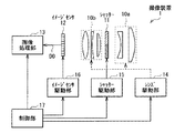
図1は、本発明の一実施の形態に係る撮像装置(撮像装置1)の全体構成を表したものである。撮像装置1は、被写体を互いに異なる複数の視点方向から撮影し、動画(または静止画)として、複数の視点画像(ここでは、左右2つの視点画像)を交互に時分割的に取得するものである。撮像装置1は、いわゆる単眼式カメラであり、シャッター制御によって左右の光路を切り替え可能となっている。この撮像装置1は、撮像レンズ10a,10b、シャッター11、イメージセンサ12、画像処理部13、レンズ駆動部14,シャッター駆動部15、イメージセンサ駆動部16および制御部17を備えている。
<Embodiment>
[Configuration of Imaging Device 1]
FIG. 1 shows the overall configuration of an imaging apparatus (imaging apparatus 1) according to an embodiment of the present invention. The
撮像レンズ10a,10bは、被写体からの光線を取得するためのレンズ群であり、これらの撮像レンズ10a,10b間に、シャッター11が配設されている。尚、シャッター11の配置は特に限定されるものではないが、理想的には、撮像レンズ10a,10bの瞳面あるいは図示しない絞りの位置に配置されることが望ましい。撮像レンズ10a,10bは、例えばいわゆるズームレンズとして機能し、レンズ駆動部14によってレンズ間隔等が調整されることにより焦点距離を変更可能となっている。但し、撮像レンズとしては、そのような可動焦点レンズに限らず、固定焦点レンズであってもよい。
The
(シャッター11の構成)
シャッター11は、左右2つの領域に分割されており、その分割された領域毎に透過(開)および遮断(閉)を切り替え可能となっている。シャッター11としては、そのような切り替えが可能なものであれば、機械式のシャッターであってもよいし、例えば液晶シャッターのような電気式のシャッターであってもよい。このシャッター11の具体的な構成については後述する。
(Configuration of shutter 11)
The
ここで、図2にシャッター11の平面構成の一例を示す。このように、シャッター11は、左右2つ(水平方向に沿った2つ)の領域(SL,SR)を有し、領域SLを開(領域SRを閉)とした状態(図2(A))と、領域SRを開(領域SLを閉)とした状態(図2(B))とが、交互に切り替わるように制御される。そのようなシャッター11の具体的な構成として、例えば液晶シャッターを例に挙げて説明する。図3は、液晶シャッターとしてのシャッター11の領域SL,SRの境界付近の断面構成を表したものである。
Here, FIG. 2 shows an example of a planar configuration of the
シャッター11は、ガラス等よりなる基板101,106間に液晶層104が封止されると共に、基板101の光入射側に偏光子107A、基板106の光出射側に検光子107Bがそれぞれ貼り合わせられたものである。基板101と液晶層104との間には電極が形成され、この電極が複数(ここでは、領域SL,SRに対応する2つ)のサブ電極102Aに分割されている。これら2つのサブ電極102Aは、個別に電圧供給が可能である。そのような基板101に対向する基板106には、領域SL,SRに共通の電極105が設けられている。尚、この基板106側の電極は、一般的には領域SL,SRに共通の電極とされるが、これに限定されず、領域毎に分割されていてもよい。サブ電極102Aと液晶層104との間には配向膜103A、電極105と液晶層104との間には配向膜103Bがそれぞれ形成されている。
In the
サブ電極102Aおよび電極105はそれぞれ、例えばITO(Indium Tin Oxide;酸化インジウムスズ)等の透明電極よりなる。偏光子107Aおよび検光子107Bはそれぞれ、所定の偏光を選択的に透過させるものであり、例えばクロスニコルまたはパラレルニコルの状態となるように配置されている。液晶層104は、例えばSTN(Super-twisted Nematic)、TN(Twisted Nematic)、OCB(Optical Compensated Bend)等の各種表示モードの液晶を含むものである。但し、液晶としては、シャッター11の閉状態から開状態(印加電圧が低から高)への遷移時の応答特性と、開状態から閉状態(印加電圧が高から低)への遷移時の応答特性とが概ね等しくなる(波形が対称形となる)ものが用いられることが望ましい。また、各状態への遷移時の応答が非常に速く、例えば、図4に示したように、閉状態から開状態へ透過率が垂直に立ち上がり(F1)、開状態から閉状態へ透過率が垂直に立ち下がる(F2)特性を示す液晶が用いられることが理想的である。このような応答特性を示す液晶としては、例えばFLC(Ferroelectric Liquid Crystal:強誘電性液晶)が挙げられる。
Each of the sub-electrode 102A and the
このような構造により、シャッター11では、サブ電極102Aおよび電極105を通じて液晶層104に電圧を印加すると、その印加電圧の大きさおよび印加時間に応じて、液晶層104の透過率を変化させることができる。即ち、シャッター11として液晶シャッターを用いることで、電圧制御によりシャッター11の開状態および閉状態を切り替えることができる。また、その電圧印加のための電極を、個別駆動が可能な2つのサブ電極102Aに分割することで、領域SL,SR毎に透光状態および遮光状態を交互に切り替え可能となる。
With such a structure, when a voltage is applied to the
イメージセンサ12は、撮像レンズ10a,10bおよびシャッター11の所定の領域を通過した光線に基づいて受光信号を出力する光電変換素子である。このイメージセンサ12は、例えばマトリクス状に配置された複数のフォトダイオード(受光画素)を有し、線順次で露出および信号読み出しを行う、ローリングシャッタータイプ(線順次駆動型)の撮像素子(例えば、CMOSセンサ)である。尚、このイメージセンサ12の受光面側には、例えば所定のカラー配列を有するR,G,Bのカラーフィルタ(図示せず)が配設されていてもよい。
The
画像処理部13は、イメージセンサ12から出力された撮像データに基づく撮像画像(左右の視点画像)に対し、所定の画像処理、例えばノイズリダクション(Noise reduction)やデモザイク処理、ガンマ補正処理等を施すものである。この画像処理部13は、そのような画像処理前あるいは画像処理後のデータを記憶する各種メモリを含んでいる。但し、画像処理後の画像データは、記録せずに外部のディスプレイ等に出力するようにしてもよい。
The
レンズ駆動部14は、撮像レンズ10a,10bにおける所定のレンズを光軸に沿ってシフトさせ、焦点距離を変化させるためのアクチュエータである。
The
シャッター駆動部15は、制御部17によるタイミング制御に応じて、シャッター11の左右の領域(SL,SR)においてその領域毎に開閉の切り替え駆動を行うものである。具体的には、シャッター11の領域SLが開状態のときには、領域SRが閉状態となるように、逆に領域SLが閉状態のときには、領域SRが開状態となるようにそれぞれ駆動する。動画撮影の際には、そのような各領域の開閉切り替えが時分割で交互に行われるように駆動する。本実施の形態では、シャッター11における左右の各領域の開期間がその領域に対応するフレーム(フレームLまたはフレームR)に1:1で対応しており、各領域の開期間と1フレーム期間とは略同一となっている。
The
イメージセンサ駆動部16は、制御部17によるタイミング制御に応じて、イメージセンサ12を駆動制御するものである。具体的には、上述のようなローリングシャッター型のイメージセンサ12において、その露出および信号読み出しをそれぞれ線順次に行うように駆動する。
The image
制御部17は、画像処理部13、レンズ駆動部14、シャッター駆動部15およびイメージセンサ駆動部16の各動作を所定のタイミングで制御するものであり、この制御部17としては例えばマイクロコンピュータ等が用いられる。詳細は後述するが、本実施の形態では、この制御部17が、シャッター11における開閉切り替えタイミングを、フレーム開始タイミング(1ライン目の露出開始タイミング)から所定の期間ずらして設定するようになっている。
The
[撮像装置1の作用、効果]
(1.基本動作)
上記のような撮像装置1では、制御部17の制御に基づき、レンズ駆動部14が撮像レンズ10a,10bを駆動すると共に、シャッター駆動部15がシャッター11における左領域を開状態、右領域を閉状態にそれぞれ切り替える。また、これらの各動作に同期して、イメージセンサ駆動部16がイメージセンサ12を駆動させる。これにより、左光路への切り替えがなされ、イメージセンサ12では、左視点方向から入射した光線に基づく左視点画像データD0Lが取得される。
[Operation and Effect of Imaging Device 1]
(1. Basic operation)
In the
続いて、シャッター駆動部15がシャッター11の右領域を開状態、左領域を閉状態にそれぞれ切り替え、イメージセンサ駆動部16がイメージセンサ12を駆動させる。これにより、右光路への切り替えがなされ、イメージセンサ12では、右視点方向から入射した光線に基づく右視点画像データD0Rが取得される。
Subsequently, the
そして、イメージセンサ12において複数のフレーム(撮像フレーム)を時系列的に取得すると共に、各撮像フレーム(後述のフレームL,R)に対応して上記シャッター11における開閉の切り替え行うことにより、左視点画像,右視点画像に対応する撮像データが時系列に沿って交互に取得され、それらの組が順次画像処理部13へ入力される。
Then, the
画像処理部13は、上記のようにして取得された左視点画像データD0L,右視点画像データD0Rに基づく撮像画像(後述の左視点画像L1,右視点画像R1)に対し、所定の画像処理を施し、例えば立体視用の左右の視点画像(後述の左視点画像L2,右視点画像R2)を生成する。生成した左視点画像L2,右視点画像R2は画像処理部13内に記録されるか、あるいは外部へ出力される。
The
(2.視点画像取得の原理)
ここで、図5〜図7を参照して、単眼式カメラを用いた場合の左右の視点画像取得の原理について説明する。図5〜図7は、撮像装置1を上方からみた図に等価であるが、簡便化のため、撮像レンズ10a,10b、シャッター11およびイメージセンサ12以外の構成要素の図示を省略しており、撮像レンズ10a,10bについても簡略化してある。
(2. Principle of viewpoint image acquisition)
Here, with reference to FIG. 5 to FIG. 7, the principle of acquiring the left and right viewpoint images when using a monocular camera will be described. 5 to 7 are equivalent to views of the
まず、図5に示したように、左右の光路切り替えをしない場合(通常の2D撮影の場合)の受光像(イメージセンサ12への映り方)について説明する。ここでは、被写体の一例として、奥行き方向において互いに異なる位置に配置された3つの被写体を例に挙げる。具体的には、撮影レンズ10a,10bのピント面S1にある被写体A(人物)と、被写体Aよりも奥側(撮像レンズと反対側)に位置する被写体B(山)と、被写体Aよりも手前側(撮像レンズ側)に位置する被写体C(花)である。このような位置関係にある場合、被写体Aが、例えばセンサ面S2上の中央付近に結像する。一方、ピント面S1よりも奥側に位置する被写体Bは、センサ面S2の手前(撮像レンズ側)に結像し、被写体Cは、センサ面S2の奥側(撮像レンズと反対側)に結像する。即ち、センサ面S2には、被写体Aがフォーカスした(ピントの合った)像(A0)、被写体Bおよび被写体Cはデフォーカスした(ぼやけた)像(B0,C0)となって映る。
First, as shown in FIG. 5, a light reception image (how to be reflected on the image sensor 12) when the left and right optical paths are not switched (in the case of normal 2D imaging) will be described. Here, as an example of the subject, three subjects arranged at different positions in the depth direction are taken as an example. Specifically, the subject A (person) on the focusing surface S1 of the photographing
(左視点画像)
このような位置関係にある3つの被写体A〜Cに対し、光路を左右で切り替えた場合、センサ面S2への映り方は、次のように変化する。例えば、シャッター駆動部15が、シャッター11の左側の領域SLを開状態、右側の領域SRを閉状態となるように駆動した場合には、図6に示したように、左側の光路が透過となり、右側の光路は遮光される。この場合、ピント面S1にある被写体Aに関しては、右側の光路を遮光されていても、光路切り替えのない上記場合と同様、センサ面S2上にフォーカスして結像する(A0)。ところが、ピント面S1から外れた位置にある被写体B,Cについては、センサ面S2上においてデフォーカスしたそれぞれの像が、水平方向において互いに逆の方向(d1,d2)にシフトしたような像(B0',C0')として映る。
(Left viewpoint image)
When the optical path is switched between right and left for the three subjects A to C having such a positional relationship, the way the image is reflected on the sensor surface S2 changes as follows. For example, when the
(右視点画像)
一方、シャッター駆動部15が、シャッター11の領域SRを開状態、領域SLを閉状態となるように駆動した場合には、図7に示したように、右側の光路が透過となり、左側の光路は遮光される。この場合も、ピント面S1にある被写体Aは、センサ面S2上に結像し、ピント面S1から外れた位置にある被写体B,Cは、センサ面S2上において互いに逆の方向(d3,d4)にシフトしたような像(B0",C0")として映る。但し、これらのシフト方向d3,d4は、上記左視点画像におけるシフト方向d1,d2とそれぞれ逆向きとなる。
(Right viewpoint image)
On the other hand, when the
(左右の視点画像間の視差)
上記のように、シャッター11における各領域の開閉を切り替えることにより、左右の各視点方向に対応する光路が切り替えられ、左視点画像L1,右視点画像R1を取得することができる。また、上述のようにデフォーカスした被写体像は、左右の視点画像間で互いに水平方向逆向きにシフトするため、その水平方向に沿った位置ずれ量(位相差)が立体感を生みだす視差量となる。例えば図8(A),(B)に示したように、被写体Bに注目した場合、左視点画像L1における像B0’の位置(B1L)と右視点画像R1における像B0”の位置(B1R)との水平方向の位置ずれ量Wb1が、被写体Bについての視差量となる。同様に、被写体Cに注目した場合、左視点画像L1における像C0’の位置(C1L)と右視点画像R1における像C0”の位置(C1R)との水平方向の位置ずれ量Wc1が、被写体Cについての視差量となる。
(Parallax between left and right viewpoint images)
As described above, by switching the opening and closing of each area in the
そして、これらの左視点画像L1,右視点画像R1を、例えば偏光方式、フレームシーケンシャル方式、プロジェクタ方式等の3D表示法を用いて表示することにより、観察者は、その観察映像において、例えば次のような立体感を感じることができる。即ち、上述の例では、視差のない被写体A(人物)は表示画面(基準面)上で観察される一方、被写体B(山)はその基準面よりも奥まって見え、被写体C(花)は基準面から飛び出したような立体感で観察される。 Then, by displaying the left viewpoint image L1 and the right viewpoint image R1 by using a 3D display method such as a polarization method, a frame sequential method, a projector method, etc., the observer can, for example, You can feel the three-dimensional effect. That is, in the above-described example, the subject A (person) having no parallax is observed on the display screen (reference plane), while the subject B (mountain) appears to be deeper than the reference plane, and the subject C (flower) is It is observed with a three-dimensional effect that protrudes from the reference plane.
(3.シャッター11,イメージセンサ12の駆動タイミング)
続いて、シャッター11における開閉切り替え動作、イメージセンサ12における露出および信号読み出し動作について、比較例(比較例1,2)を挙げて詳細に説明する。図9(A),(B)は、比較例1に係るイメージセンサ(CCD)の露出・読み出しタイミングおよびシャッターの開閉切り替えタイミングを模式的に表したものである。また、図10(A),(B)には、比較例2に係るイメージセンサ(CMOS)の露出・読み出しタイミングおよびシャッターの開閉切り替えタイミングを模式的に表したものである。尚、本明細書において、フレーム期間frは、動画としての1フレーム期間を2分割にした期間に相当するものである(2fr=動画としての1フレーム期間)。また、(A)図において斜線部分は、露出期間に相当している。尚、ここでは、動画撮影の場合を例に挙げて説明するが、静止画撮影の場合も同様である。
(3. Drive timing of
Subsequently, the opening / closing switching operation in the
(比較例1)
CCDをイメージセンサとして用いた比較例1では、面順次で画面一括駆動されるため、図9(A)に示したように、一画面(撮像画面)内において露出期間に時間的なずれがなく、信号の読み出し(Read)も同時刻になされる。また、左視点画像を撮影するための露出期間では、左領域100Lが開(右領域100Rが閉)となるように、右視点画像を撮影するための露出期間では、右領域100Rが開(左領域100Lが閉)となるように、シャッターが切り替えられる。具体的には、露出開始(フレーム期間開始)タイミングに同期して、左領域100L,右領域100Rの開閉が切り替えられる。また、比較例1では、左領域100Lおよび右領域100Rの開期間はそれぞれ、フレーム期間frに等しく、また露出期間にも等しくなっている。
(Comparative Example 1)
In Comparative Example 1 in which the CCD is used as an image sensor, the screen is driven in a frame-sequential manner, so that there is no time lag in the exposure period in one screen (imaging screen) as shown in FIG. Signal reading is also performed at the same time. Further, the
(比較例2)
ところが、イメージセンサとして、例えばローリングシャッタータイプのCMOSセンサを用いた場合、上記CCDの場合と異なり、例えば画面上から画面下に向かって(走査方向Sに沿って)線順次で駆動がなされる。即ち、図10(A)に示したように、一画面内において、ライン毎に露出開始のタイミングや信号読み出し(Read)のタイミングが異なってくる。このため、画面内の位置によって、露出期間に時間的なずれが生じる。このようなCMOSセンサを用いた場合、1ライン目の露出開始タイミングに同期してシャッターの開閉を切り替える(図10(B))と、1画面全体(全ライン)の露出が終了する前に、透過光路が切り替わってしまう。
(Comparative Example 2)
However, when a rolling shutter type CMOS sensor, for example, is used as the image sensor, unlike the CCD, for example, the image sensor is driven line-sequentially from the top of the screen to the bottom of the screen (along the scanning direction S). That is, as shown in FIG. 10A, the exposure start timing and the signal read (Read) timing are different for each line in one screen. For this reason, a time lag occurs in the exposure period depending on the position in the screen. When such a CMOS sensor is used, the opening and closing of the shutter is switched in synchronization with the exposure start timing of the first line (FIG. 10B), before the exposure of the entire screen (all lines) is completed. The transmitted light path is switched.
この結果、左視点画像L100,右視点画像R100では、互いに異なる光路の通過光線が混ざって受光され、いわゆる左右のクロストークが発生する。例えば、左視点画像L100の撮影フレームでは、左光路の通過光線の受光量が画面上から画面下に向けて徐々に減る一方、右光路の通過光線の受光量は画面上から画面下に向けて徐々に増える。これにより、例えば図11(A)に示したように、左視点画像L100では、上部D1が主に左視点方向からの光線、下部D3が主に右視点方向からの光線に基づくものとなり、中央付近D2では、各視点方向からの光線が混在して(クロストークにより)視差量が低減する。同様に、右視点画像R100においても、例えば図11(B)に示したように、上部D1が主に右視点方向からの光線、下部D3が主に左視点方向からの光線に基づくものとなり、中央付近D2ではクロストークにより視差量が低減してしまう。尚、図11における色の濃淡は、各視点方向成分の偏りを表しており、色が濃い程、左右どちらかの視点方向からの光線の受光量が多いことを表している。 As a result, in the left viewpoint image L100 and the right viewpoint image R100, light beams passing through different optical paths are mixed and received, and so-called left and right crosstalk occurs. For example, in the shooting frame of the left viewpoint image L100, the amount of light passing through the left optical path gradually decreases from the top of the screen toward the bottom of the screen, while the amount of light passing through the right optical path decreases from the top of the screen toward the bottom of the screen. Gradually increase. Thus, for example, as shown in FIG. 11A, in the left viewpoint image L100, the upper portion D1 is mainly based on the light rays from the left viewpoint direction, and the lower portion D3 is mainly based on the light rays from the right viewpoint direction. In the vicinity D2, light rays from the respective viewpoint directions are mixed (due to crosstalk), and the amount of parallax is reduced. Similarly, in the right viewpoint image R100, as shown in FIG. 11B, for example, the upper part D1 is mainly based on light rays from the right viewpoint direction, and the lower part D3 is mainly based on light rays from the left viewpoint direction. In the vicinity of the center D2, the amount of parallax is reduced due to crosstalk. The shades of color in FIG. 11 represent the deviation of each viewpoint direction component, and the darker the color, the greater the amount of light received from either the left or right viewpoint direction.
従って、そのような左右の視点画像を所定の方法で表示した場合、画面中央付近では視差量が低減している(あるいは無い)ために、立体的な表示ができず(平面的な2D画像に近づく)、また、画像(画面)の上下では所望の立体感が得られなくなってしまう。 Therefore, when such left and right viewpoint images are displayed by a predetermined method, the amount of parallax is reduced (or absent) in the vicinity of the center of the screen, so that stereoscopic display cannot be performed (a flat 2D image is obtained). The desired stereoscopic effect cannot be obtained at the top and bottom of the image (screen).
これに対し、本実施の形態では、各フレーム(撮像フレーム)L,Rにおいて、シャッター11における開閉切り替えを、イメージセンサ12における1ライン目の露出開始タイミングから所定の期間遅延して行う。具体的には、図12に示したように、1ライン目の露出開始タイミングt0から、露出期間Tの1/2の期間遅延して、シャッター11の領域SL,SRの開閉を切り替える。換言すると、ここでは、走査方向Sにおける中央のラインの露出開始タイミングt1において、シャッター11の領域SL,SRの開閉を切り替えることに等しい。これにより、各フレームL,Rでは、画面上部および下部においてシャッター11の領域SL,SRの両方の通過光線が混在して受光されるが、中央付近においては主に所望の視点方向からの通過光線が受光される。
In contrast, in the present embodiment, in each frame (imaging frame) L, R, the opening / closing switching in the
具体的には、図13(A)に示したように、フレームLに対応する左視点画像L1では、左視点方向からの光線の受光量は画面中央付近において最も多く、画面上下端部に向かって徐々に減少する。一方、右視点方向からの光線の受光量は、画面中央付近において最も少なく、画面上下端部に向かって徐々に増加する。また、図13(B)に示したように、フレームRに対応する右視点画像R1では、右視点方向からの光線の受光量は画面中央付近において最も多く、画面上下端部に向かって徐々に減少する。一方、左視点方向からの光線の受光量は、画面中央付近において最も少なく、画面上下端部に向かって徐々に増加する。尚、図13(A),(B)における色の濃淡は、各視点方向成分の偏りを表しており、色が濃い程、左視点方向(または右視点方向)からの光線の受光量の割合が多いことを表している。 Specifically, as shown in FIG. 13A, in the left viewpoint image L1 corresponding to the frame L, the amount of light received from the left viewpoint direction is the largest near the center of the screen and is directed toward the upper and lower ends of the screen. Gradually decreases. On the other hand, the amount of light received from the right viewpoint direction is the smallest near the center of the screen and gradually increases toward the upper and lower ends of the screen. Further, as shown in FIG. 13B, in the right viewpoint image R1 corresponding to the frame R, the amount of light received from the right viewpoint direction is the largest near the center of the screen, and gradually toward the upper and lower ends of the screen. Decrease. On the other hand, the amount of light received from the left viewpoint direction is the smallest near the center of the screen and gradually increases toward the upper and lower ends of the screen. The shades of color in FIGS. 13A and 13B represent the bias of each viewpoint direction component, and the darker the color, the proportion of the amount of received light from the left viewpoint direction (or right viewpoint direction). It means that there are many.
これにより、図13(C)に示したように、左視点画像L1および右視点画像R1間における視差量は、画面中央において最も大きく、画面上下端部に向けて徐々に低減する。尚、ここでは、画面上下端部(最上部および最下部の各ライン)において左右の視点方向からの光線の受光量が1/2ずつで等しくなるため、その視差量は0(ゼロ)となる。また、本実施の形態では、露出期間Tおよびシャッター11における領域SL,SRの開期間がフレーム期間fr(例えば8.3ms)に等しく、1ライン目の露出開始タイミングから、T/2の期間(例えば4.15ms)遅延して、シャッター11の開閉が切り替えられる。
As a result, as shown in FIG. 13C, the amount of parallax between the left viewpoint image L1 and the right viewpoint image R1 is the largest at the center of the screen and gradually decreases toward the upper and lower ends of the screen. Note that, here, the received light amount from the left and right viewpoint directions is equal by half at the upper and lower end portions of the screen (the uppermost and lowermost lines), so the parallax amount is 0 (zero). . In the present embodiment, the exposure period T and the open periods of the areas SL and SR in the
ところで一般に、観察者が表示された映像を観察する際に、表示画面において最も注視する部分は画面中央付近であることが多い。上述のように、本実施の形態では、所望の視点方向からの光線が画面中央付近において毎フレーム受光され、その画面中央付近において左右の視差量を生じさせるため、観察者が注視する部分に効率的に立体感を付与することができる。 By the way, in general, when an observer observes a displayed image, the most watched portion on the display screen is often near the center of the screen. As described above, in this embodiment, light rays from a desired viewpoint direction are received every frame near the center of the screen, and left and right parallax amounts are generated near the center of the screen. A stereoscopic effect can be imparted.
一方、画面上下付近では、各視点方向からの光線が混在することになるため、画面中央付近に比べ、視差量が低減する(あるいは無くなる)が、これは観察者の視認性にはさほど大きな影響を与えない(画面中央付近から上下端部にかけての視差量の変化を感じにくい)。特に、極僅かな視差量で(微小視差を用いて)立体映像表示を行う場合には、観察者がそのような視差量の変化に気付くことは稀である。これは、例えば以下のような理由による。 On the other hand, near the top and bottom of the screen, light rays from each viewpoint direction coexist, so the amount of parallax is reduced (or eliminated) compared to the vicinity of the center of the screen, but this has a significant effect on the visibility of the observer. (It is difficult to feel the change in the amount of parallax from the vicinity of the center of the screen to the upper and lower ends). In particular, when stereoscopic image display is performed with a very small amount of parallax (using minute parallax), the observer rarely notices such a change in the amount of parallax. This is due to the following reasons, for example.
即ち、人間が感じる立体感は、観察対象となっている物の配置、大きさ、色、その他の物との対比等、様々な要素を総合的に加味して判断されるものであるので、上記のような視差量の変化が直接的に立体感に影響を与えることは少ない。 In other words, the three-dimensional feeling felt by humans is determined by comprehensively considering various elements such as the arrangement, size, color, and contrast with other objects to be observed. Such a change in the amount of parallax hardly affects the stereoscopic effect directly.
あるいは、観察対象の物体が観察者にとって既知のものである場合には、観察者はその物体についての立体感を先入観や経験に基づいて無意識のうちに補正するため、上記のような視差量の変化に気付きにくい。例えば、画面の下部から上部に向かって直立したビルの絵を立体表示した場合、上記のような視差量の変化に伴い、実際にはビルの中央付近から上下端にかけてビルの輪郭が歪んだように映るが、観察者にとってビルは通常真っすぐなものとして認識されていることが多いため、そのようなビルの歪みに気付かずに、「真っすぐなビル」として視認され易い。 Alternatively, when the object to be observed is known to the observer, the observer unconsciously corrects the stereoscopic effect on the object based on preconceptions and experiences. Difficult to notice changes. For example, when a 3D picture of a building standing upright from the bottom to the top of the screen is displayed, it seems that the outline of the building is actually distorted from near the center of the building to the top and bottom with changes in the amount of parallax. However, since a building is usually recognized as a straight one by an observer, it is easily recognized as a “straight building” without noticing such distortion of the building.
以上のように、本実施の形態では、各撮像フレームにおいて、シャッター11を制御して各領域の開閉切り替えを、イメージセンサ12における1ライン目の露出開始から所定の期間遅延して行うようにしたので、イメージセンサ12では、特に観察者によって注視され易い画面中央付近において、所望の視点方向からの光線を他の視点方向からの光線よりも多く受光することができる。よって、線順次駆動型の撮像素子を用いて、精度良く複数の視点画像を取得することが可能となる。
As described above, in the present embodiment, in each imaging frame, the
また、上記遅延期間を、イメージセンサ12における露出期間Tの1/2の期間とすることにより、所望の視点方向の光線の受光量が画面中央において最も大きく画面上下端部に向って徐々に低減すると共に、画面上部と下部との間で受光される各視点方向の光線のバランスが同等となる。遅延期間が、露出期間の1/2でない場合、画面上部と下部との間で、受光される各視点方向の光線バランスが崩れてしまう。このような場合、例えば画面上部で右画像の割合が多ければ、画面下部では左画像の割合が多くなる。従って、画面上部での立体感が正しい場合(撮像フレームが右視点方向のフレームである場合)、画面下部では左右逆の視点画像を見ることになるので、画面上下での立体感が逆転する現象が発生してしまう。このため、シャッター11の開閉切り替えタイミングは、上述のように露出期間Tの1/2の期間遅延させることが望ましい。
In addition, by setting the delay period to a half of the exposure period T in the
(画面上下部で視差量が低減することによるメリット)
一方、画面の上部および下部において、上記のように視差量が低減することで、次のようなメリットがある。例えば、実際の立体表示時には、これら左右の視点画像を所定の手法によりディスプレイ等に表示することになるが、この場合、表示される映像のうち上下端部付近における立体感は、ディスプレイの額縁の影響を受け易い。具体的には、図14に示したように、ディスプレイ200において映像表示を行う場合、観察者の眼には、表示された映像と共に額縁200aが映ることとなる。例えば、上述の例のように、表示画面上に人物A2が表示され、山B2が表示画面よりも奥まって、花C2は表示画面から飛び出すような立体表示を行った場合、例えば領域E2付近では、花C2に対する距離感と、額縁200aの下枠に対する距離感が相違し、これらが競合してしまうことがある。同様に、領域E1付近では、山B2に対する距離感と、額縁200aの上枠に対する距離感とが競合することがある。そのため、表示された映像が、額縁200aの枠表面と同一面(表示画面)上に引きずられて(立体感が押し戻されて)、違和感を生じることがある。このような額縁200aによる立体感への影響は、特に表示画面上下の領域E1,E2で顕著に表れる。これは、ディスプレイが一般に横長(例えばアスペクト比が16:9)であることが多く、額縁200aが水平方向(左右方向)よりも垂直方向(上下方向)において視認され易いためである。また、特に額縁200aよりも手前側(観察者側)に飛び出すような立体感で表示した映像(ここでは、領域E2における花C2)が、上記のような額縁200aの影響を受け易い。
(Advantages of reducing the amount of parallax at the top and bottom of the screen)
On the other hand, reducing the amount of parallax at the top and bottom of the screen as described above has the following advantages. For example, at the time of actual stereoscopic display, these left and right viewpoint images are displayed on a display or the like by a predetermined method. In this case, the stereoscopic effect in the vicinity of the upper and lower end portions of the displayed video is the display frame. Easy to be affected. Specifically, as shown in FIG. 14, when displaying an image on the
この点において、本実施の形態では、上述のように画面の中央から上下端部に向かって視差量が徐々に低減していくため、額縁200a付近の領域E1,E2では視差量が極僅かとなる。従って、額縁200a付近の領域E1,E2では、表示映像がほぼ額縁200aの表面近傍に表示されるため上記のような距離感の違いによる競合が生じにくく、自然な見え方となる。 In this regard, in the present embodiment, as described above, the amount of parallax gradually decreases from the center of the screen toward the upper and lower ends, so that the amount of parallax is extremely small in the regions E1 and E2 near the frame 200a. Become. Therefore, in the areas E1 and E2 in the vicinity of the frame 200a, the display image is displayed almost in the vicinity of the surface of the frame 200a, so that the competition due to the difference in distance as described above hardly occurs and the image looks natural.
次に、上記実施の形態に係る撮像装置の変形例(変形例1〜3)について説明する。変形例1,2は、上記撮像装置1におけるイメージセンサ12の露出期間およびシャッター11の開閉切り替えタイミングの他の例に関するものであり、上記実施の形態と同様の撮像光学系に適用されるものである。変形例3は、撮像装置の他の構成(2眼式カメラ)に関するものである。以下では、上記実施の形態の撮像装置1と同様の構成要素については同一の符号を付し、適宜説明を省略する。
Next, modified examples (modified examples 1 to 3) of the imaging apparatus according to the above embodiment will be described.
<変形例1>
図15(A),(B)は、変形例1に係るイメージセンサ(CMOS)の露出・読み出しタイミングおよびシャッターの開閉切り替えタイミングを模式的に表したものである。本変形例においても、上記実施の形態と同様、線順次駆動型のイメージセンサ12において、1ライン目の露出開始タイミングから所定の期間遅延してシャッター11の開閉を切り替えるようになっている。また、シャッター11における各領域の開期間がその領域に対応するフレーム(フレームLまたはフレームR)に1:1で対応しており、各領域の開期間と1フレーム期間とは略同一である。但し、本変形例では、イメージセンサ12において、1ライン毎の露出期間を短縮(フレーム期間fr>露出期間T’)する。このとき、フレーム期間frの開始と同時に1ライン目の露出を開始し、露出期間T’の経過時に信号読み出しを行う(信号読み出しのタイミングを所定の期間早め、露出開始タイミングは変更しない)。
<
FIGS. 15A and 15B schematically show exposure / reading timing and shutter opening / closing switching timing of the image sensor (CMOS) according to the first modification. Also in this modified example, in the line-sequential drive
イメージセンサ12における露出期間は、例えば電子シャッター機能等を利用して調整可能である。ここでは、フレーム期間fr(=シャッター11の開期間(閉期間))を8.3msとし、露出可能時間の60%程度まで露出期間を短縮する(露出期間T’=8.3×0.6=5ms)。また、シャッター11の開閉切り替えは、上記実施の形態と同様、1ライン目の露出開始タイミングから、例えばこの露出期間T’の1/2の期間(2.5ms)だけ遅延して行う。
The exposure period in the
これにより、各フレームL,Rでは、画面上部および下部においてシャッター11の領域SL,SRの両方の通過光線が混在して受光されるが、中央付近においては主に所望の視点方向からの通過光線が受光される。但し、本変形例では、上記実施の形態に比べ、所望の視点方向の光線が取得される範囲(走査方向Sに沿った範囲)が広くなる。
As a result, in each frame L and R, the light passing through both the areas SL and SR of the
具体的には、図16(A)に示したように、左視点画像L1では、左視点方向からの光線の受光量は画面中央付近において最も多く、画面上下端部に向かって徐々に減少する。一方、右視点方向からの光線は、画面中央付近では受光されず、画面上下端部付近においてのみ受光される。また、図16(B)に示したように、右視点画像R1では、右視点方向からの光線の受光量は画面中央付近において最も多く、画面上下端部に向かって徐々に減少する。一方、左視点方向からの光線は、画面中央付近では受光されず、画面上下端部付近においてのみ受光される。尚、図16(A),(B)における色の濃淡は、各視点方向成分の偏りを表しており、色が濃い程、左視点方向(または右視点方向)からの光線の受光量の割合が多いことを表している。 Specifically, as shown in FIG. 16A, in the left viewpoint image L1, the amount of light received from the left viewpoint direction is the largest near the center of the screen and gradually decreases toward the upper and lower ends of the screen. . On the other hand, light rays from the right viewpoint direction are not received near the center of the screen, but only near the upper and lower ends of the screen. Further, as shown in FIG. 16B, in the right viewpoint image R1, the amount of light received from the right viewpoint direction is the largest near the center of the screen and gradually decreases toward the upper and lower ends of the screen. On the other hand, light rays from the left viewpoint direction are not received near the center of the screen, but only near the upper and lower ends of the screen. The shades of color in FIGS. 16A and 16B represent the deviation of each viewpoint direction component, and the darker the color, the proportion of the received light amount from the left viewpoint direction (or right viewpoint direction). It means that there are many.
これにより、図16(C)に示したように、左視点画像L1および右視点画像R1間における視差量は、画面中央から画面上下端部近傍まで広範囲にわたって大きくなり、画面上下端部近傍から上下端部に向かって低減する。尚、ここでは、画面上下端部(最上部および最下部の各ライン)において左右の視点方向からの光線の受光量が1/2ずつで等しくなるため、その視差量は0(ゼロ)となる。 As a result, as shown in FIG. 16C, the amount of parallax between the left viewpoint image L1 and the right viewpoint image R1 increases over a wide range from the center of the screen to the vicinity of the upper and lower ends of the screen, and increases and decreases from the vicinity of the upper and lower ends of the screen. Reduce towards the edge. Note that, here, the received light amount from the left and right viewpoint directions is equal by half at the upper and lower end portions of the screen (the uppermost and lowermost lines), so the parallax amount is 0 (zero). .
本変形例のように、露出期間T’を短縮した場合であっても、上記実施の形態と同等の効果を得ることができる。また、露出期間T’の短縮により、各フレームL,Rにおいて所望の視点方向からの光線の受光範囲(異なる視点方向からの光線に対する受光量の割合が大きくなる範囲)を広げ、画面内における視差形成範囲を拡大させることができる。即ち、フレーム期間frに対して露出期間T’を短くする程、各フレームでは対応する視点方向からの光線の受光範囲を広げることができる。 Even in the case where the exposure period T ′ is shortened as in this modification, the same effect as in the above embodiment can be obtained. Also, by shortening the exposure period T ′, the light receiving range of light rays from the desired viewpoint direction (the range in which the ratio of the amount of received light with respect to the light rays from different viewpoint directions) is increased in each frame L and R, and the parallax within the screen The formation range can be expanded. That is, the shorter the exposure period T ′ with respect to the frame period fr, the wider the light receiving range of the light from the corresponding viewpoint direction in each frame.
<変形例2>
図17(A),(B)は、変形例2に係るイメージセンサ(CMOS)の露出・読み出しタイミングおよびシャッターの開閉切り替えタイミングを模式的に表したものである。本変形例では、上記変形例1と同様、イメージセンサ12において、1ライン毎の露出期間を短縮(フレーム期間fr>露出期間T’)するが、露出開始および信号読み出しタイミングが上記変形例1と異なっている。具体的には、本変形例では、フレーム期間frが開始してから所定の期間経過後に1ライン目の露出を開始し、露出期間T’の経過時に信号読み出しを行う(露出開始のタイミングを所定の期間遅延させ、信号読み出しタイミングは変更しない)。尚、ここでも、フレーム期間fr(=シャッター11の開期間(閉期間))を例えば8.3msとし、露出可能時間の60%程度まで露出期間を短縮する(露出期間T’=8.3×0.6=5ms)。また、シャッター11の開閉切り替えは、上記実施の形態と同様、1ライン目の露出開始タイミングから、例えばこの露出期間T’の1/2の期間(2.5ms)だけ遅延して行う。
<
FIGS. 17A and 17B schematically show exposure / reading timing and shutter opening / closing switching timing of the image sensor (CMOS) according to the second modification. In the present modification, the exposure period for each line is shortened (frame period fr> exposure period T ′) in the
これにより、各フレームL,Rでは、画面上部および下部においてシャッター11の領域SL,SRの両方の通過光線が混在して受光されるが、中央付近においては主に所望の視点方向からの通過光線が受光される。また、上記変形例1と同様、所望の視点方向の光線が取得される範囲(走査方向Sに沿った範囲)が広くなる(図18(A),(B))。即ち、左視点画像L1,右視点画像R1間における視差量は、画面中央から画面上下端部近傍まで広範囲にわたって大きく、画面上下端部近傍から上下端部に向かって低減する。
As a result, in each frame L and R, the light passing through both the areas SL and SR of the
本変形例のように、露出期間T’を短縮する際、信号読み出しタイミングを変更せずに、露出開始タイミングを遅らせるようにしてもよい。このようにした場合であっても、上記実施の形態および上記変形例1と同等の効果を得ることができる。 As in this modification, when the exposure period T ′ is shortened, the exposure start timing may be delayed without changing the signal readout timing. Even in this case, it is possible to obtain the same effects as those of the above embodiment and the first modification.
<変形例3>
本変形例では、上記撮像装置1における制御部17が、上述のタイミング制御(シャッター11の開閉タイミングを所定の期間遅延させる制御)を行うモードを第1のモードとし、この第1のモードと、以下に説明する第2のモードとを切り替え可能となっている。第1のモードとしては、例えば上記実施の形態で説明したようなタイミング制御(露出期間=フレーム期間)の他、上記変形例1,2で説明したようなタイミング制御(露出期間<フレーム期間)であってもよい。
<Modification 3>
In this modification, the mode in which the
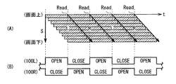
(第2のモード)
図19(A),(B)は、第2のモードにおけるイメージセンサ(CMOS)の露出・読み出しタイミングおよびシャッターの開閉切り替えタイミングを模式的に表したものである。このように、第2のモードでは、左右の視点画像に対応するフレームを1フレームおきに交互に有効フレームとして取得するようになっている。
(Second mode)
FIGS. 19A and 19B schematically show the exposure / read timing of the image sensor (CMOS) and the opening / closing switching timing of the shutter in the second mode. Thus, in the second mode, frames corresponding to the left and right viewpoint images are alternately acquired as effective frames every other frame.
具体的には、制御部17が、ある時刻に取得されるフレーム(フレームL’)と、このフレームL’の全ライン分の読み出し終了以降(露出終了以降)に1ライン目の露出が開始されたフレーム(フレームR’)とをそれぞれ有効フレームとして取得する。換言すると、フレームL’後のフレームであって、フレームL’の全ライン分の読み出しが終了する前(全ライン分の露出が終了する前)に露出開始となるフレーム(フレームL’,R’間のフレームX)は、無効フレームとする。このフレームXについては、例えば、読み出し終了後、画像処理部13において各種処理部へ出力しないようにするか、あるいは読み出し自体を行わないようにすればよい。
Specifically, the
また、図19(B)に示したように、シャッター11の領域SL,SRの各開期間(閉期間)を、例えばフレーム期間fr(ここでは、フレーム期間fr=露出期間T)の2倍の長さとなるように、シャッター11の開閉を切り替える。このように、第2のモードでは、1フレームおきに取得されたフレームL’,R’,…を有効フレームとし、シャッター11における開期間をフレーム期間frの2倍に設定する。
Further, as shown in FIG. 19B, each open period (closed period) of the areas SL and SR of the
前述のように、線順次駆動型のイメージセンサでは、各フレームの画面中央付近においてクロストークが生じ易いが、この第2のモードのように、1フレームおきにフレームL’,R’を取得し、シャッター11の開期間をフレーム期間の2倍とした場合には、クロストークの生じるフレーム(フレームX)が排除される。また、各フレームL’,R’の全ライン分の露出期間Tにおいて、シャッター11の開閉が切り替わることがない(領域SR,SLが開状態あるいは閉状態のまま維持される)。このため、図20(A)に示したように、フレームL’に対応する左視点画像L’1では、画面全域において左視点方向からの光線のみが受光される。また、図20(B)に示したように、フレームR’に対応する右視点画像R’1では、画面全域において右視点方向からの光線のみが受光される。即ち、この第2のモードにおいても、精度良く左右の視点画像を取得可能である。
As described above, in the line sequential drive type image sensor, crosstalk is likely to occur near the center of the screen of each frame. However, as in the second mode, frames L ′ and R ′ are acquired every other frame. When the
(モードの切り替え)
ここで、上記実施の形態等で説明した第1のモードでは、フレームを間引くことなく撮影すること(毎フレーム撮影)が可能であるため、実質的にフレームを間引く第2のモードよりも、光利用効率が高い。一方、第2のモードでは、画面全域においてクロストークが生じにくい(一画面内で視差量が一定である)ため、画面中央付近と上下において視差量の異なる第1のモードよりも、より精度良く視点画像を取得可能である。
(Switching mode)
Here, in the first mode described in the above embodiment and the like, since it is possible to shoot without thinning out frames (shooting every frame), the light is substantially lighter than in the second mode of thinning out frames. High usage efficiency. On the other hand, in the second mode, since crosstalk hardly occurs in the entire screen (the amount of parallax is constant within one screen), the second mode has higher accuracy than the first mode in which the amount of parallax differs between near the center of the screen and above and below. A viewpoint image can be acquired.
従って、第1のモードと第2のモードとの切り替えは、例えば被写体の明るさに応じて行うようにするとよい。明るさについての判断は、例えば制御部17に搭載されたAE(automatic exposure:自動露出)機能(図示せず)等を利用して行うことができ、例えば明るさが所定の閾値未満の場合には第1のモード、閾値以上の場合には第2のモードを実行する。これにより、例えば、室内等の光量が十分でない場所で撮影を行う場合には第1のモードへ、屋外等の光量が十分な場所で撮影を行う場合には第2のモードへ、それぞれ自動的に切り替えることができる。あるいは、これらのモード切り替えを、ユーザ等の手動により(外部入力信号に基づいて)行うようにしてもよい。
Therefore, the switching between the first mode and the second mode may be performed according to the brightness of the subject, for example. The determination about the brightness can be made by using, for example, an AE (automatic exposure) function (not shown) mounted on the
本変形例のように、シャッター11の開閉タイミングを遅延させて視点画像を取得する第1のモードと、1フレームおきに視点画像を取得する第2のモードとを自動または手動により切り換えるようにしてもよい。これにより、上記実施の形態等と同等の効果を得ることができると共に、被写体の明るさに応じて適切な視点画像撮影を行うことができる。
As in this modification, the first mode for acquiring the viewpoint image by delaying the opening and closing timing of the
<変形例4>
[撮像装置2の全体構成]
図21は、変形例4に係る撮像装置(撮像装置2)の全体構成を表したものである。撮像装置2は、上記実施の形態の撮像装置1と同様、被写体を左右の視点方向から撮影し、動画(または静止画)として、左右の視点画像を時系列的に取得するものである。但し、本変形例の撮像装置2は、左右の各視点方向からの光線LL,LRを取得するための光路毎に、撮像レンズ10a1,10b、および撮像レンズ10a2,10bを有する、いわゆる2眼式カメラであり、光路毎にシャッター11a,11bを有している。但し、撮像レンズ10bは、各光路に共通の構成要素である。また、各光路に共通の構成要素として、上記実施の形態の撮像装置1と同様、イメージセンサ12、画像処理部13、レンズ駆動部18、シャッター駆動部19、イメージセンサ駆動部16および制御部17を備えている。
<Modification 4>
[Overall Configuration of Imaging Device 2]
FIG. 21 illustrates an overall configuration of an imaging apparatus (imaging apparatus 2) according to Modification 4. The
撮像レンズ10a1,10bは、左視点方向の光線LLを、撮像レンズ10a2,10bは、右視点方向の光線LRをそれぞれ取得するためのレンズ群である。撮像レンズ10a1,10b間にはシャッター11a、撮像レンズ10a2,10b間にはシャッター11bがそれぞれ配設されている。尚、シャッター11a,11bの配置は特に限定されるものではないが、理想的には撮像レンズ群の瞳面あるいは図示しない絞りの位置に配置されることが望ましい。
The imaging lenses 10a1 and 10b are lens groups for acquiring the light beam LL in the left viewpoint direction, and the imaging lenses 10a2 and 10b are the lens group for acquiring the light beam LR in the right viewpoint direction. A shutter 11a is disposed between the imaging lenses 10a1 and 10b, and a
これらの撮像レンズ10a1,10b(撮像レンズ10a2,10b)は、全体として例えばズームレンズとして機能するものである。撮像レンズ10a1,10b(撮像レンズ10a2,10b)では、レンズ駆動部14によってレンズ間隔等が調整されることにより、焦点距離を可変となっている。また、各レンズ群はそれぞれ1または複数枚のレンズによって構成されている。そのような撮像レンズ10a1とシャッター11aとの間にはミラー110、撮像レンズ10a2とシャッター11bとの間にはミラー111、シャッター11a,11b間にはミラー112がそれぞれ配置されている。これらのミラー110〜112によって、光線LL,LRはそれぞれ、シャッター11a,11bを通過した後、撮像レンズ10bへ入射するようになっている。
These imaging lenses 10a1 and 10b (imaging lenses 10a2 and 10b) function as a zoom lens as a whole, for example. In the imaging lenses 10a1 and 10b (imaging lenses 10a2 and 10b), the lens distance and the like are adjusted by the
シャッター11a,11bは、左右の各光路における透過および遮断を切り替えるためのものであり、シャッター11a,11b毎に開状態(透光状態)および閉状態(遮光状態)が切り替え制御されるようになっている。シャッター11a,11bとしては、上記のような光路切り替えが可能なものであれば、機械式のシャッターであってもよいし、例えば液晶シャッターのような電気式のシャッターであってもよい。
The
レンズ駆動部18は、撮像レンズ10a1,10b(または撮像レンズ10a2,10b)における所定のレンズを光軸に沿ってシフトさせるアクチュエータである。
The
シャッター駆動部19は、シャッター11a,11bの開閉切り替え駆動を行うものである。具体的には、シャッター11aが開状態のときには、シャッター11bが閉状態となるように、シャッター11aが閉状態のときには、シャッター11bが開状態となるようにそれぞれ駆動する。また、動画として各視点画像を取得する際には、シャッター11a,11b毎に開状態および閉状態が時分割で交互に入れ替わるように駆動するようになっている。
The
[撮像装置2の作用、効果]
上記のような撮像装置2では、制御部17の制御に基づき、レンズ駆動部18が撮像レンズ10a1,10bを駆動すると共に、シャッター駆動部19がシャッター11aを開状態、シャッター11bを閉状態にそれぞれ切り替える。また、これらの各動作に同期して、イメージセンサ駆動部16がイメージセンサ12を受光駆動させる。これにより、左視点方向に対応する左光路に切り替えられ、イメージセンサ12では、被写体側からの入射光線のうち光線LLに基づく受光がなされ、左視点画像データD0Lが取得される。
[Operation and Effect of Imaging Device 2]
In the
続いて、レンズ駆動部18が撮像レンズ10a2,10bを駆動すると共に、シャッター駆動部19がシャッター11bを開状態、シャッター11aを閉状態にそれぞれ切り替える。また、これらの各動作に同期して、イメージセンサ駆動部16がイメージセンサ12を受光駆動させる。これにより、右視点方向に対応する右光路に切り替えられ、イメージセンサ12では、被写体側からの入射光線のうち光線LRに基づく受光がなされ、右視点画像データD0Rが取得される。上記のような撮像レンズ10a1,10a2およびシャッター11a,11bの切り替え駆動を時分割で交互に行うことにより、左視点画像,右視点画像に対応する撮像データが時系列に沿って交互に取得され、それら左右の視点画像の組が順次画像処理部13へ入力される。
Subsequently, the
このとき、上記実施の形態と同様、各撮像フレームにおいて、シャッター11における各領域の開閉切り替えを、イメージセンサ12における1ライン目の露出開始から所定の期間遅延して行う。これにより、イメージセンサ12では、特に観察者によって注視され易い画面中央付近において、所望の視点方向からの通過光線を他の視点方向からの光線よりも多く受光することができる。よって、線順次駆動型のイメージセンサ12を用いて、精度良く複数の視点画像を取得することが可能となる。
At this time, similarly to the above-described embodiment, in each imaging frame, switching of opening / closing of each region in the
そして、画像処理部13が、上記のようにして取得された左視点画像データD0L,右視点画像データD0Rに基づく撮像画像に対し、所定の画像処理を施し、例えば立体視用の左右の視点画像を生成する。生成された視点画像は画像処理部13内に記録されるか、あるいは外部へ出力される。
Then, the
上述のように、本発明は、撮像レンズを左右の光路毎に配置してなる2眼式カメラにも適用可能である。このような撮像光学系を用いた場合であっても、シャッター11における開閉切り替えを、イメージセンサ12の1ライン目の露出開始から所定の期間遅延して行うことで、上記実施の形態と同等の効果を得ることができる。また、本変形例の撮像装置2においても、上述の変形例1,2で説明した各タイミング制御を行うようにしてもよいし、上記変形例3で説明したモード切り替えを行ってもよい。
As described above, the present invention can also be applied to a twin-lens camera in which an imaging lens is arranged for each of the left and right optical paths. Even in the case of using such an imaging optical system, switching between opening and closing in the
以上、実施の形態および変形例を挙げて本発明を説明したが、本発明はこれらの実施の形態等に限定されるものではなく、種々の変形が可能である。例えば、上記実施の形態等では、左右2つの光路を切り替えて左右2つの視点画像に対して所定の画像処理を施す場合を例に挙げて説明したが、視点方向は左右(水平方向)に限らず上下(垂直方向)であってもよい。 Although the present invention has been described with reference to the embodiment and the modification examples, the present invention is not limited to the embodiment and the like, and various modifications can be made. For example, in the above-described embodiment and the like, the case where predetermined image processing is performed on the two left and right viewpoint images by switching the two left and right optical paths has been described as an example, but the viewpoint direction is limited to the left and right (horizontal direction). It may be up and down (vertical direction).
また、光路を3つ以上に切り替え可能とし、3つ以上の多視点画像が取得されるようにしてもよい。この場合、例えば、上記実施の形態における撮像装置1のように、シャッターを複数の領域に分割してもよいし、あるいは上記変形例4における撮像装置2のように、複数のシャッターを光路毎に設けてもよい。
In addition, the optical path may be switched to three or more, and three or more multi-view images may be acquired. In this case, for example, the shutter may be divided into a plurality of regions as in the
一例として、図22に、3つの領域SA,SB,SCを有するシャッター(3つの光路にそれぞれ設けられたシャッターSA,SB,SCも同様)を用いて3つの視点画像を取得する場合のイメージセンサの駆動タイミングとシャッターの開閉切り替えタイミングを模式的に示す。尚、ここでは、上記実施の形態等のうち変形例1において説明した信号読み出しタイミングを早めて露出期間を短縮する場合(露出期間T’<フレーム期間fr)を例に挙げる。このように、3光路を切り替えて3つの視点方向からの光線に基づく視点画像をそれぞれ取得する場合も、上述の左右の視点画像撮影時と同様、イメージセンサ12の1ライン目の露出開始から所定の期間(T’/2)遅延してシャッターの開閉を切り替えればよい。
As an example, FIG. 22 shows an image sensor in which three viewpoint images are acquired using a shutter having three areas SA, SB, and SC (the same applies to shutters SA, SB, and SC provided in three optical paths, respectively). The drive timing and shutter opening / closing switching timing are schematically shown. Here, the case where the exposure period is shortened by shortening the signal readout timing described in the first modification in the above-described embodiment and the like (exposure period T ′ <frame period fr) is taken as an example. As described above, when the viewpoint images based on the light rays from the three viewpoint directions are acquired by switching the three optical paths, the predetermined timing from the start of exposure of the first line of the
具体的には、フレームAの撮影時には、その1ライン目の露光開始からT’/2遅延して領域SAを閉状態から開状態へ切り替えると共に、領域SCを開状態から閉状態へ切り替える(領域SBは閉状態のまま)。続いて、フレームBの撮影時には、その1ライン目の露光開始からT’/2遅延して領域SBを開状態へ切り替えると共に、領域SAを閉状態へ切り替える(領域SCは閉状態のまま)。同様に、フレームCの撮影時には、その1ライン目の露光開始からT’/2遅延して領域SCを開状態へ切り替えると共に、領域SBを閉状態へ切り替える(領域SAは閉状態のまま)。これにより、上記実施の形態等と同様、3つの視点画像では、その画面中央付近において所望の視点方向からの光線を受光し易くなる。よって、上記実施の形態および変形例1と同等の効果を得ることができる。
Specifically, at the time of shooting the frame A, the region SA is switched from the closed state to the open state with a delay of T ′ / 2 from the start of exposure of the first line, and the region SC is switched from the open state to the closed state (region). SB remains closed). Subsequently, at the time of shooting the frame B, the region SB is switched to the open state with a delay of T ′ / 2 from the start of exposure of the first line, and the region SA is switched to the closed state (the region SC remains closed). Similarly, at the time of shooting the frame C, the region SC is switched to the open state with a delay of T ′ / 2 from the start of exposure of the first line, and the region SB is switched to the closed state (the region SA remains closed). Thus, as in the above-described embodiment, the three viewpoint images can easily receive light rays from the desired viewpoint direction in the vicinity of the center of the screen. Therefore, an effect equivalent to that of the above embodiment and
また、上記実施の形態等では、シャッターにおける開閉タイミングを、露出期間の1/2の期間遅延する場合を例に挙げて説明したが、遅延期間は必ずしも露出期間の1/2でなくともよい。但し、露出期間の1/2に設定することにより、画面上下での左右の視差バランスを取りやすくなる。露出期間の1/2ではない場合には、画面上下で左右の視差バランスが崩れるが、これはシャッターの開期間の長さを調整することで回避可能である。 In the above embodiment and the like, the case where the opening / closing timing of the shutter is delayed by a half of the exposure period has been described as an example. However, the delay period may not necessarily be a half of the exposure period. However, by setting the exposure period to ½, it becomes easier to balance the left and right parallax at the top and bottom of the screen. When the exposure period is not ½, the left / right parallax balance is lost at the top and bottom of the screen, but this can be avoided by adjusting the length of the shutter open period.
1,2…撮像装置、10a,10a1,10a2,10b…撮像レンズ、11,11a,11b…シャッター、12…イメージセンサ、13…画像処理部、14,18…レンズ駆動部、15,19…シャッター駆動部、16…イメージセンサ駆動部、17…制御部、L1…左視点画像、R1…右視点画像。
DESCRIPTION OF
Claims (9)
複数の光路において各光路の透過および遮断を切り替え可能なシャッターと、
露出および信号読み出しが線順次になされる複数の受光画素を含み、各光路の通過光線に基づく撮像データを取得する撮像素子と、
前記シャッターにおける各光路の透過および遮断の切り替えを制御する制御部とを備え、
前記制御部は、各撮像フレームにおいて前記撮像素子における1ライン目の露出開始から所定の期間遅延して各光路の透過および遮断が切り替わるように前記シャッターを制御する
撮像装置。 An imaging lens;
A shutter capable of switching between transmission and blocking of each optical path in a plurality of optical paths;
An image sensor that includes a plurality of light-receiving pixels in which exposure and signal readout are performed in a line sequential manner, and obtains imaging data based on light rays passing through each optical path;
A control unit for controlling switching between transmission and blocking of each optical path in the shutter,
The control unit controls the shutter so that transmission and blocking of each optical path are switched after a predetermined period from the start of exposure of the first line in the imaging element in each imaging frame.
前記撮像素子における1ライン目の露出開始時期から、露出期間の1/2の期間遅延して、各光路の透過および遮断が切り替わるように前記シャッターを制御する
請求項1に記載の撮像装置。 The controller is
The imaging apparatus according to claim 1, wherein the shutter is controlled such that transmission and blocking of each optical path are switched with a delay of ½ of an exposure period from the exposure start timing of the first line in the imaging element.
請求項2に記載の撮像装置。 The imaging apparatus according to claim 2, wherein the control unit controls an exposure period for one line in the imaging element to be shorter than a frame period.
請求項3に記載の撮像装置。 The imaging device according to claim 3, wherein the control unit advances signal readout timing of the first line in the imaging element in each imaging frame.
請求項3に記載の撮像装置。 The imaging device according to claim 3, wherein the control unit delays the exposure start timing of the first line in the imaging element in each imaging frame.
請求項1に記載の撮像装置。 The imaging device according to claim 1, wherein the shutter has a response characteristic that is substantially the same as a response characteristic when transitioning from the transmission state to the blocking state and a response characteristic when shifting from the blocking state to the transmission state.
請求項6に記載の撮像装置。 The imaging device according to claim 6, wherein the shutter is a liquid crystal shutter using a ferroelectric liquid crystal.
前記制御部は、
被写体の明るさまたは外部入力信号に応じて、
前記第1のモードと、前記撮像素子から出力された撮像データに基づく、左右の視点画像を1フレームおきに交互に有効フレームとして取得する第2のモードとを切り替え可能となっている
請求項1に記載の撮像装置。 In the control unit, in each imaging frame, a mode in which the shutter is controlled so that transmission and blocking of each optical path are switched after a predetermined period from the start of exposure of the first line in the imaging element is set as a first mode. ,
The controller is
Depending on subject brightness or external input signal,
2. The first mode and a second mode in which left and right viewpoint images are alternately acquired as effective frames every other frame based on imaging data output from the imaging device can be switched. The imaging device described in 1.
前記撮像素子において、時間的に連続する複数のフレームのうち、少なくとも第1のフレームと、前記第1のフレームの全ライン分の露出終了以降に1ライン目の露出が開始された第2のフレームとをそれぞれ前記有効フレームとして取得し、
各有効フレームのフレーム開始時期に同期して、各光路の透過および遮断が切り替わるように前記シャッターを制御する
請求項8に記載の撮像装置。 In the second mode,
In the imaging device, at least a first frame among a plurality of temporally continuous frames, and a second frame in which exposure of the first line is started after completion of exposure for all lines of the first frame. And each as the effective frame,
The imaging device according to claim 8, wherein the shutter is controlled so that transmission and blocking of each optical path are switched in synchronization with a frame start time of each effective frame.
Priority Applications (4)
| Application Number | Priority Date | Filing Date | Title |
|---|---|---|---|
| JP2010151401A JP5556448B2 (en) | 2010-07-01 | 2010-07-01 | Imaging device |
| EP11169690.2A EP2403255B1 (en) | 2010-07-01 | 2011-06-13 | Image pickup apparatus |
| CN2011101740118A CN102316264A (en) | 2010-07-01 | 2011-06-24 | Camera head |
| US13/169,269 US8934051B2 (en) | 2010-07-01 | 2011-06-27 | Image pickup apparatus for acquiring a plurality of viewpoint images |
Applications Claiming Priority (1)
| Application Number | Priority Date | Filing Date | Title |
|---|---|---|---|
| JP2010151401A JP5556448B2 (en) | 2010-07-01 | 2010-07-01 | Imaging device |
Publications (3)
| Publication Number | Publication Date |
|---|---|
| JP2012015863A JP2012015863A (en) | 2012-01-19 |
| JP2012015863A5 JP2012015863A5 (en) | 2013-08-01 |
| JP5556448B2 true JP5556448B2 (en) | 2014-07-23 |
Family
ID=44582101
Family Applications (1)
| Application Number | Title | Priority Date | Filing Date |
|---|---|---|---|
| JP2010151401A Expired - Fee Related JP5556448B2 (en) | 2010-07-01 | 2010-07-01 | Imaging device |
Country Status (4)
| Country | Link |
|---|---|
| US (1) | US8934051B2 (en) |
| EP (1) | EP2403255B1 (en) |
| JP (1) | JP5556448B2 (en) |
| CN (1) | CN102316264A (en) |
Families Citing this family (10)
| Publication number | Priority date | Publication date | Assignee | Title |
|---|---|---|---|---|
| JP5594067B2 (en) * | 2010-11-02 | 2014-09-24 | ソニー株式会社 | Image processing apparatus and image processing method |
| KR20120071964A (en) * | 2010-12-23 | 2012-07-03 | 삼성전자주식회사 | Stereoscopic image photographing apparatus |
| DE102011106453A1 (en) * | 2011-07-04 | 2013-01-10 | Carl Zeiss Ag | Method and device for time sequential recording of three-dimensional images |
| US9456735B2 (en) * | 2012-09-27 | 2016-10-04 | Shahinian Karnig Hrayr | Multi-angle rear-viewing endoscope and method of operation thereof |
| KR102006731B1 (en) * | 2012-10-17 | 2019-08-02 | 삼성전자주식회사 | Liquid crystal shutter and image capturing apparatus |
| US10110813B1 (en) * | 2016-04-27 | 2018-10-23 | Ambarella, Inc. | Multi-sensor camera using rolling shutter sensors |
| JP7102114B2 (en) * | 2016-11-11 | 2022-07-19 | キヤノン株式会社 | Photoelectric conversion element, image sensor and image sensor |
| CN109525765A (en) * | 2018-12-21 | 2019-03-26 | 浙江晶鲸科技有限公司 | High-speed image acquisition system and image-pickup method with FLC Light Valve |
| CN109660707A (en) * | 2018-12-27 | 2019-04-19 | 浙江晶鲸科技有限公司 | Image-pickup method and system suitable for high-speed mobile target |
| WO2020190602A1 (en) * | 2019-03-18 | 2020-09-24 | Corning Incorporated | Enhanced imaging device using liquid lens, embedded digital signal processor, and software |
Family Cites Families (13)
| Publication number | Priority date | Publication date | Assignee | Title |
|---|---|---|---|---|
| JPS6411167A (en) | 1987-07-02 | 1989-01-13 | Toray Silicone Co | Covering material composition |
| GB9324047D0 (en) | 1993-11-23 | 1994-01-12 | Watts Jonathan | Image detecting apparatus |
| JPH1060618A (en) | 1996-08-19 | 1998-03-03 | Kobe Steel Ltd | Formation of sprayed coating, sprayed coating formed by using the same and thermal spraying material powder |
| JPH10271534A (en) * | 1997-03-26 | 1998-10-09 | Nippon Hoso Kyokai <Nhk> | Stereoscopic image photographing device |
| JP2000137203A (en) | 1998-11-02 | 2000-05-16 | Mitsui Chemicals Inc | Stereoscopic picture taking device |
| JP2002027499A (en) * | 2000-07-03 | 2002-01-25 | Canon Inc | Imaging apparatus and its controlling method |
| JP2002034056A (en) | 2000-07-18 | 2002-01-31 | Scalar Corp | Device and method for picking up stereoscopic image |
| JP2002095015A (en) * | 2000-09-11 | 2002-03-29 | Canon Inc | Image pickup system, lens unit and imaging device |
| JP2004228810A (en) * | 2003-01-21 | 2004-08-12 | Canon Inc | Accessory for stereoscopic imaging |
| TWI245198B (en) * | 2004-09-01 | 2005-12-11 | Via Tech Inc | Deinterlace method and method for generating deinterlace algorithm of display system |
| KR100588744B1 (en) * | 2004-09-09 | 2006-06-12 | 매그나칩 반도체 유한회사 | Shutter module using line scan type image sensor and control method of it |
| JP4645692B2 (en) * | 2008-07-18 | 2011-03-09 | ソニー株式会社 | Imaging device |
| JP5112283B2 (en) | 2008-12-26 | 2013-01-09 | 株式会社ヤマト | Equipment control system |
-
2010
- 2010-07-01 JP JP2010151401A patent/JP5556448B2/en not_active Expired - Fee Related
-
2011
- 2011-06-13 EP EP11169690.2A patent/EP2403255B1/en not_active Not-in-force
- 2011-06-24 CN CN2011101740118A patent/CN102316264A/en active Pending
- 2011-06-27 US US13/169,269 patent/US8934051B2/en not_active Expired - Fee Related
Also Published As
| Publication number | Publication date |
|---|---|
| EP2403255A2 (en) | 2012-01-04 |
| EP2403255A3 (en) | 2012-08-15 |
| JP2012015863A (en) | 2012-01-19 |
| EP2403255B1 (en) | 2014-12-24 |
| CN102316264A (en) | 2012-01-11 |
| US20120002099A1 (en) | 2012-01-05 |
| US8934051B2 (en) | 2015-01-13 |
Similar Documents
| Publication | Publication Date | Title |
|---|---|---|
| JP5556448B2 (en) | Imaging device | |
| JP5594067B2 (en) | Image processing apparatus and image processing method | |
| JP5577772B2 (en) | Imaging device | |
| US9699440B2 (en) | Image processing device, image processing method, non-transitory tangible medium having image processing program, and image-pickup device | |
| JP5628913B2 (en) | Imaging apparatus and imaging method | |
| US8780185B2 (en) | Image pickup apparatus having a display controlled using interchangeable lens information and/or finder information | |
| JP2012100101A5 (en) | ||
| US10574906B2 (en) | Image processing apparatus and image processing method | |
| JP2014026051A (en) | Image capturing device and image processing device | |
| US20120307016A1 (en) | 3d camera | |
| JP2005173270A (en) | Optical device for stereoscopic photography, photographing device, and system and device for stereoscopic photography | |
| JP4208351B2 (en) | Imaging apparatus, convergence distance determination method, and storage medium | |
| JP2011244377A (en) | Imaging apparatus and image processing system, image processing method, and image processing program | |
| WO2016199381A1 (en) | Image processing apparatus and image processing method | |
| JP2001016617A (en) | Image pickup device, its convergence control method, storage medium and optical device | |
| JP2011030123A (en) | Imaging apparatus, control method of the same, and computer program | |
| WO2013031348A1 (en) | Imaging device | |
| US10567662B2 (en) | Imaging device and control method therefor using shift direction calculation | |
| JP6036784B2 (en) | Image processing apparatus, image processing method, image processing program, and recording medium | |
| TWI746370B (en) | Head mounted display apparatus | |
| JP2003092769A (en) | Stereoscopic video imaging apparatus | |
| JP2023114724A (en) | Stereoscopic imaging apparatus, control method and program | |
| JP2023116360A (en) | Control unit, electronic apparatus, control method, and program | |
| JP2024008154A (en) | Image processing device, display device, and image processing method | |
| JP2002027498A (en) | Apparatus for imaging three-dimensional video |
Legal Events
| Date | Code | Title | Description |
|---|---|---|---|
| A521 | Request for written amendment filed |
Free format text: JAPANESE INTERMEDIATE CODE: A523 Effective date: 20130612 |
|
| A621 | Written request for application examination |
Free format text: JAPANESE INTERMEDIATE CODE: A621 Effective date: 20130612 |
|
| A977 | Report on retrieval |
Free format text: JAPANESE INTERMEDIATE CODE: A971007 Effective date: 20131213 |
|
| A131 | Notification of reasons for refusal |
Free format text: JAPANESE INTERMEDIATE CODE: A131 Effective date: 20131217 |
|
| A521 | Request for written amendment filed |
Free format text: JAPANESE INTERMEDIATE CODE: A523 Effective date: 20140115 |
|
| TRDD | Decision of grant or rejection written | ||
| A01 | Written decision to grant a patent or to grant a registration (utility model) |
Free format text: JAPANESE INTERMEDIATE CODE: A01 Effective date: 20140507 |
|
| A61 | First payment of annual fees (during grant procedure) |
Free format text: JAPANESE INTERMEDIATE CODE: A61 Effective date: 20140520 |
|
| R151 | Written notification of patent or utility model registration |
Ref document number: 5556448 Country of ref document: JP Free format text: JAPANESE INTERMEDIATE CODE: R151 |
|
| R250 | Receipt of annual fees |
Free format text: JAPANESE INTERMEDIATE CODE: R250 |
|
| R250 | Receipt of annual fees |
Free format text: JAPANESE INTERMEDIATE CODE: R250 |
|
| R250 | Receipt of annual fees |
Free format text: JAPANESE INTERMEDIATE CODE: R250 |
|
| R250 | Receipt of annual fees |
Free format text: JAPANESE INTERMEDIATE CODE: R250 |
|
| LAPS | Cancellation because of no payment of annual fees |