JP5555892B2 - Micro / nano bubble generating method, generating nozzle and generating device - Google Patents
Micro / nano bubble generating method, generating nozzle and generating device Download PDFInfo
- Publication number
- JP5555892B2 JP5555892B2 JP2013006945A JP2013006945A JP5555892B2 JP 5555892 B2 JP5555892 B2 JP 5555892B2 JP 2013006945 A JP2013006945 A JP 2013006945A JP 2013006945 A JP2013006945 A JP 2013006945A JP 5555892 B2 JP5555892 B2 JP 5555892B2
- Authority
- JP
- Japan
- Prior art keywords
- micro
- gas
- liquid
- nozzle
- generating
- Prior art date
- Legal status (The legal status is an assumption and is not a legal conclusion. Google has not performed a legal analysis and makes no representation as to the accuracy of the status listed.)
- Active
Links
- 239000002101 nanobubble Substances 0.000 title claims description 200
- 238000000034 method Methods 0.000 title claims description 68
- 239000007788 liquid Substances 0.000 claims description 291
- 239000007789 gas Substances 0.000 claims description 116
- XLYOFNOQVPJJNP-UHFFFAOYSA-N water Substances O XLYOFNOQVPJJNP-UHFFFAOYSA-N 0.000 claims description 56
- CURLTUGMZLYLDI-UHFFFAOYSA-N Carbon dioxide Chemical compound O=C=O CURLTUGMZLYLDI-UHFFFAOYSA-N 0.000 claims description 16
- MHAJPDPJQMAIIY-UHFFFAOYSA-N Hydrogen peroxide Chemical compound OO MHAJPDPJQMAIIY-UHFFFAOYSA-N 0.000 claims description 10
- CBENFWSGALASAD-UHFFFAOYSA-N Ozone Chemical compound [O-][O+]=O CBENFWSGALASAD-UHFFFAOYSA-N 0.000 claims description 10
- VLTRZXGMWDSKGL-UHFFFAOYSA-N perchloric acid Chemical compound OCl(=O)(=O)=O VLTRZXGMWDSKGL-UHFFFAOYSA-N 0.000 claims description 10
- 239000007864 aqueous solution Substances 0.000 claims description 9
- 239000000243 solution Substances 0.000 claims description 9
- IJGRMHOSHXDMSA-UHFFFAOYSA-N Atomic nitrogen Chemical compound N#N IJGRMHOSHXDMSA-UHFFFAOYSA-N 0.000 claims description 8
- QVGXLLKOCUKJST-UHFFFAOYSA-N atomic oxygen Chemical compound [O] QVGXLLKOCUKJST-UHFFFAOYSA-N 0.000 claims description 8
- 239000001569 carbon dioxide Substances 0.000 claims description 8
- 229910002092 carbon dioxide Inorganic materials 0.000 claims description 8
- 229910001873 dinitrogen Inorganic materials 0.000 claims description 8
- 239000001301 oxygen Substances 0.000 claims description 8
- 229910052760 oxygen Inorganic materials 0.000 claims description 8
- 239000004033 plastic Substances 0.000 claims description 8
- 229920003023 plastic Polymers 0.000 claims description 8
- UFHFLCQGNIYNRP-UHFFFAOYSA-N Hydrogen Chemical compound [H][H] UFHFLCQGNIYNRP-UHFFFAOYSA-N 0.000 claims description 6
- XTEGARKTQYYJKE-UHFFFAOYSA-N chloric acid Chemical compound OCl(=O)=O XTEGARKTQYYJKE-UHFFFAOYSA-N 0.000 claims description 5
- 229940005991 chloric acid Drugs 0.000 claims description 5
- 239000011259 mixed solution Substances 0.000 claims description 5
- 239000012286 potassium permanganate Substances 0.000 claims description 5
- 239000000203 mixture Substances 0.000 claims description 4
- 239000012141 concentrate Substances 0.000 claims description 2
- 239000011859 microparticle Substances 0.000 claims 1
- 238000007670 refining Methods 0.000 claims 1
- 238000004140 cleaning Methods 0.000 description 30
- 230000001954 sterilising effect Effects 0.000 description 22
- 239000002245 particle Substances 0.000 description 19
- 238000004659 sterilization and disinfection Methods 0.000 description 19
- 239000004065 semiconductor Substances 0.000 description 17
- 230000000694 effects Effects 0.000 description 12
- 238000011109 contamination Methods 0.000 description 9
- 229910052751 metal Inorganic materials 0.000 description 9
- 239000002184 metal Substances 0.000 description 9
- 239000002667 nucleating agent Substances 0.000 description 8
- 230000007423 decrease Effects 0.000 description 7
- 235000013305 food Nutrition 0.000 description 7
- 238000002347 injection Methods 0.000 description 7
- 239000007924 injection Substances 0.000 description 7
- 235000012431 wafers Nutrition 0.000 description 6
- 238000003780 insertion Methods 0.000 description 5
- 230000037431 insertion Effects 0.000 description 5
- 230000005514 two-phase flow Effects 0.000 description 5
- 239000002585 base Substances 0.000 description 4
- 230000000052 comparative effect Effects 0.000 description 4
- 238000007599 discharging Methods 0.000 description 4
- 239000012535 impurity Substances 0.000 description 4
- 238000004519 manufacturing process Methods 0.000 description 4
- 239000011347 resin Substances 0.000 description 4
- 229920005989 resin Polymers 0.000 description 4
- 239000000126 substance Substances 0.000 description 4
- 235000013311 vegetables Nutrition 0.000 description 4
- 239000000654 additive Substances 0.000 description 3
- 239000012153 distilled water Substances 0.000 description 3
- 238000005553 drilling Methods 0.000 description 3
- 229910021645 metal ion Inorganic materials 0.000 description 3
- 230000001590 oxidative effect Effects 0.000 description 3
- 230000035699 permeability Effects 0.000 description 3
- -1 polyethylene Polymers 0.000 description 3
- 238000005406 washing Methods 0.000 description 3
- 238000007796 conventional method Methods 0.000 description 2
- 238000010586 diagram Methods 0.000 description 2
- 238000011978 dissolution method Methods 0.000 description 2
- 238000009826 distribution Methods 0.000 description 2
- 238000005516 engineering process Methods 0.000 description 2
- 230000007613 environmental effect Effects 0.000 description 2
- 238000012856 packing Methods 0.000 description 2
- 238000012545 processing Methods 0.000 description 2
- 229920000106 Liquid crystal polymer Polymers 0.000 description 1
- 239000004977 Liquid-crystal polymers (LCPs) Substances 0.000 description 1
- FYYHWMGAXLPEAU-UHFFFAOYSA-N Magnesium Chemical compound [Mg] FYYHWMGAXLPEAU-UHFFFAOYSA-N 0.000 description 1
- 206010067482 No adverse event Diseases 0.000 description 1
- 239000004696 Poly ether ether ketone Substances 0.000 description 1
- 229930182556 Polyacetal Natural products 0.000 description 1
- 239000004952 Polyamide Substances 0.000 description 1
- 239000004695 Polyether sulfone Substances 0.000 description 1
- 239000004698 Polyethylene Substances 0.000 description 1
- 239000004734 Polyphenylene sulfide Substances 0.000 description 1
- 239000004743 Polypropylene Substances 0.000 description 1
- 239000004809 Teflon Substances 0.000 description 1
- 229920006362 Teflon® Polymers 0.000 description 1
- 239000002253 acid Substances 0.000 description 1
- 230000000996 additive effect Effects 0.000 description 1
- 239000000853 adhesive Substances 0.000 description 1
- 230000001070 adhesive effect Effects 0.000 description 1
- 230000002411 adverse Effects 0.000 description 1
- 239000003513 alkali Substances 0.000 description 1
- 230000015572 biosynthetic process Effects 0.000 description 1
- 230000009172 bursting Effects 0.000 description 1
- 239000000919 ceramic Substances 0.000 description 1
- 239000003795 chemical substances by application Substances 0.000 description 1
- 230000003247 decreasing effect Effects 0.000 description 1
- 238000013461 design Methods 0.000 description 1
- 239000003599 detergent Substances 0.000 description 1
- 238000011161 development Methods 0.000 description 1
- 229920006351 engineering plastic Polymers 0.000 description 1
- 238000002474 experimental method Methods 0.000 description 1
- 238000002309 gasification Methods 0.000 description 1
- 238000009434 installation Methods 0.000 description 1
- 229910052749 magnesium Inorganic materials 0.000 description 1
- 239000011777 magnesium Substances 0.000 description 1
- 238000012423 maintenance Methods 0.000 description 1
- 239000000463 material Substances 0.000 description 1
- 150000002739 metals Chemical class 0.000 description 1
- 239000003607 modifier Substances 0.000 description 1
- 239000008239 natural water Substances 0.000 description 1
- 238000006386 neutralization reaction Methods 0.000 description 1
- 239000007800 oxidant agent Substances 0.000 description 1
- 230000003647 oxidation Effects 0.000 description 1
- 238000007254 oxidation reaction Methods 0.000 description 1
- 230000035515 penetration Effects 0.000 description 1
- 238000007747 plating Methods 0.000 description 1
- 229920002647 polyamide Polymers 0.000 description 1
- 239000004417 polycarbonate Substances 0.000 description 1
- 229920000515 polycarbonate Polymers 0.000 description 1
- 229920006393 polyether sulfone Polymers 0.000 description 1
- 229920002530 polyetherether ketone Polymers 0.000 description 1
- 229920000573 polyethylene Polymers 0.000 description 1
- 239000005020 polyethylene terephthalate Substances 0.000 description 1
- 229920000139 polyethylene terephthalate Polymers 0.000 description 1
- 229920006324 polyoxymethylene Polymers 0.000 description 1
- 229920001955 polyphenylene ether Polymers 0.000 description 1
- 229920000069 polyphenylene sulfide Polymers 0.000 description 1
- 229920001155 polypropylene Polymers 0.000 description 1
- 230000002035 prolonged effect Effects 0.000 description 1
- 239000002994 raw material Substances 0.000 description 1
- 230000003014 reinforcing effect Effects 0.000 description 1
- 229920006395 saturated elastomer Polymers 0.000 description 1
- 239000007921 spray Substances 0.000 description 1
- 238000005728 strengthening Methods 0.000 description 1
- 239000008399 tap water Substances 0.000 description 1
- 235000020679 tap water Nutrition 0.000 description 1
- 239000002349 well water Substances 0.000 description 1
- 235000020681 well water Nutrition 0.000 description 1
Images


Classifications
-
- B—PERFORMING OPERATIONS; TRANSPORTING
- B08—CLEANING
- B08B—CLEANING IN GENERAL; PREVENTION OF FOULING IN GENERAL
- B08B3/00—Cleaning by methods involving the use or presence of liquid or steam
- B08B3/02—Cleaning by the force of jets or sprays
Description
本発明は、水撃を利用したマイクロ・ナノバブルの発生方法、発生ノズル及び発生装置に関する。 The present invention relates to a method for generating micro / nano bubbles using water hammer, a generating nozzle, and a generating apparatus.
マイクロ・ナノバブルによる洗浄・殺菌方法は、水と空気と微量の添加剤のみを使用した環境負荷の少ない方法であるために、従来の洗剤や薬剤等の薬品を使用する洗浄・殺菌に代わるものとして注目されている。また、安全性が高いことから、野菜や食品等の殺菌方法としての適用も検討されている。従来のマイクロ・ナノバブル発生方法は、気液2相流旋回方式、ベンチューリー管方式、加圧溶解法の3方式が知られている(例えば、気液2相流旋回方式及び加圧溶解法については、それぞれ特許文献1及び2を参照)。
The cleaning and sterilization method using micro / nano bubbles is a method that uses only water, air, and a small amount of additives and has a low environmental impact. Therefore, it is an alternative to cleaning and sterilization using conventional detergents and chemicals. Attention has been paid. Moreover, since it is highly safe, application as a sterilization method for vegetables, foods, and the like is also being studied. Three conventional micro / nano bubble generation methods are known: a gas-liquid two-phase flow swirling method, a venturi tube method, and a pressure dissolution method (for example, a gas-liquid two-phase flow swirling method and a pressure dissolution method). (See
しかしながら、何れの発生方式ともマイクロ・ナノバブルの発生粒子数はまだまだ少なく、十分でない。また、マイクロバブル水は3方式とも簡単に発生させることはできるが、十分なマイクロ・ナノバブルの発生粒子数を得るためにはマイクロバブル水に塩基やマグネシューム等の核剤を入れて発生させる必要がある。核剤の混入は半導体や食品等の洗浄・殺菌への適用拡大に対して大きな妨げとなっているが、現状では、純水を用いてマイクロ・ナノバブルを大量に発生させることは非常に難しい。 However, in any generation method, the number of micro / nano bubbles generated is still small and not sufficient. In addition, microbubble water can be easily generated in all three systems, but in order to obtain a sufficient number of micro / nano bubble particles, it is necessary to generate microbubble water by adding a nucleating agent such as a base or magnesium into the microbubble water. is there. The mixing of the nucleating agent has greatly hindered the expansion of application to cleaning and sterilization of semiconductors and foods, but at present, it is very difficult to generate a large amount of micro / nano bubbles using pure water.
また、水と空気と微量の添加剤で発生させる装置の駆動ポンプは各種方式のポンプが使用可能で有るが、半導体や食品等の洗浄・殺菌等の用途により駆動ポンプを含む装置構成部品は全て金属コンタミのない装置も必要である。例えば、半導体のウェハーなどを金属コンタミを無くして洗浄する場合、マイクロ・ナノバブル発生装置で使用するポンプは、接液部を全て金属イオンなどを一切発生させないもので作り、かつ吐出圧力が安定して、且つ0.3〜0.6Mpaが必要である。 In addition, various types of pumps can be used as drive pumps for devices that generate water, air, and a small amount of additives. However, all device components including drive pumps are used for cleaning and sterilization of semiconductors and foods. A device free of metal contamination is also needed. For example, when cleaning semiconductor wafers without metal contamination, the pumps used in the micro / nano bubble generator are made with all the wetted parts not generating any metal ions and the discharge pressure is stable. And 0.3 to 0.6 Mpa is required.
そこで、回転を利用したポンプで起こることが危惧されるコンタミ現象を避けるために回転を使用しないで液を送るポンプとして、本発明者らは接液部の全ての部分をフッ素樹脂で作成した圧縮空気駆動のベローズシリンダポンプを使用した装置を提案した(特許文献3〜4)。コンタミの影響を無くして清浄な洗浄を行うという目的を達成するためには、ポンプだけでなく、マイクロバルブを発生させるノズルの部分も全てフッ素樹脂等を用いて樹脂化する技術開発が望まれている。
Therefore, as a pump that sends liquid without using rotation in order to avoid a contamination phenomenon that is feared to occur with a pump using rotation, the present inventors have used compressed air in which all parts of the wetted part are made of fluororesin. An apparatus using a driving bellows cylinder pump has been proposed (
従来技術では、核剤等を使用しないで純水のみでマイクロ・ナノバブルを大量に発生させることは極めて困難であり、仮に核剤を添加する場合でも、その添加量を大幅に低減することが求められている。また、マイクロ・ナノバブルの発生量を従来技術よりも大量にすることができれば、洗浄・殺菌効果の大幅な向上が期待できるだけでなく、様々な用途への展開が可能となる。そのため、従来技術に代わる新方式によるマイクロ・ナノバブル発生方法、及びその方法を実現できるマイクロ・ナノバブル発生装置が強く望まれている。 In the prior art, it is extremely difficult to generate a large amount of micro / nano bubbles with pure water alone without using a nucleating agent, and even if a nucleating agent is added, it is required to significantly reduce the amount of addition. It has been. In addition, if the amount of micro / nano bubbles generated can be made larger than that in the prior art, not only can the cleaning and sterilization effect be significantly improved, but it can also be expanded to various uses. Therefore, there is a strong demand for a micro / nano bubble generation method using a new method that replaces the prior art, and a micro / nano bubble generation device that can implement the method.
また、当該分野では、従来からコンタミの無いマイクロ・ナノバブルの発生を行えるシステムを構築することが求められている。上記で述べたように、接液部の全ての部分をフッ素樹脂で作成した圧縮空気駆動のベローズシリンダポンプを適用することによって、この課題は解決できる見通しが得られている。さらに、このポンプを用いたマイクロ・ナノバブル発生装置を用いて、バブルの発生量を従来よりも大量にすることができれば、半導体装置の製造において配線の微細化という技術動向に対して有効な洗浄方法となることが期待される。しかしながら、現状では、メタルフリーの材質で構成される装置においてバブル発生量を多くできるような高機能なものは得られていない。 Further, in this field, it is conventionally required to construct a system that can generate micro / nano bubbles without contamination. As described above, it is expected that this problem can be solved by applying a compressed air-driven bellows cylinder pump in which all parts of the liquid contact part are made of fluororesin. In addition, if a micro / nano bubble generator using this pump can be used to produce a larger amount of bubbles than in the past, an effective cleaning method for the technological trend of finer wiring in the manufacture of semiconductor devices It is expected to be However, at present, no highly functional device capable of increasing the amount of bubble generation has been obtained in an apparatus composed of a metal-free material.
したがって、ポンプを含めて、他の構成部品である発生ノズル、気液混合槽、液送備品等についても総合的に構造及び形状の最適化を行うことによって、新方式によるマイクロ・ナノバブルの発生方法を確立するとともに、高機能のマイクロ・ナノバブル発生装置の開発が強く求められている。最終的には、コンタミの無いマイクロ・ナノバブル発生を行えるシステムを構築することが必要である。 Therefore, a new method for generating micro-nano bubbles by optimizing the structure and shape of the other components, including pumps, as well as generating nozzles, gas-liquid mixing tanks, liquid delivery equipment, etc. In addition, there is a strong demand for the development of highly functional micro / nano bubble generators. Finally, it is necessary to construct a system that can generate micro / nano bubbles without contamination.
以上のような背景に鑑み、本発明は、純水のみでマイクロ・ナノバブルを大量に発生させて清浄な洗浄・殺菌を行うだけでなく、コンタミの無いマイクロ・ナノバブル発生を行えるシステムを構築するために、従来技術とは異なる新規な水撃方式のマイクロ・ナノバブルの発生方法、発生ノズル及び自動調整気液混合槽を含むマイクロ・ナノバブル発生装置を提供することを目的とする。 In view of the background as described above, the present invention not only performs clean cleaning and sterilization by generating a large amount of micro / nano bubbles with pure water alone, but also constructs a system capable of generating micro / nano bubbles without contamination. Another object of the present invention is to provide a novel water hammer type micro / nano bubble generation method different from the prior art, a micro / nano bubble generation device including a generation nozzle and a self-adjusting gas-liquid mixing tank.
上記の課題を解決するための基本になる考えは、溶存気体を含むマイクロ・ナノバブルを大量に作るために、非圧縮性の水がぶつかることでおこる激しい水撃を利用することにある。それを実現するために、マイクロ・ナノバブルの発生方法及び発生装置において、水撃力を最大限に発揮できるように発生ノズルの構造と形状を最適化するとともに、マイクロ・ナノバブルの大量発生を促進するような構成を有する発生装置を構築することによって本発明に到った。 The basic idea for solving the above problem is to use intense water hammer caused by collision of incompressible water in order to make a large number of micro-nano bubbles containing dissolved gas. In order to realize this, in the generation method and generation device of micro / nano bubbles, the structure and shape of the generation nozzle are optimized so as to maximize the water hammer force, and the generation of a large number of micro / nano bubbles is promoted. The present invention has been achieved by constructing a generator having such a configuration.
すなわち、本発明の構成は以下の通りである。
[1]本発明は、水撃力を利用してマイクロ・ナノバブルを発生させるための方法であって、気液混合の状態にある溶存液を、2以上の貫通小穴を周方向に有する筒の外部から該貫通小穴を通して大気圧以上の圧力で噴射させるときに、前記筒の径方向断面と平行な同一平面上で対向するように配置された前記2以上の貫通小穴のそれぞれの開口部から噴射した溶存液を前記筒の中心に水撃が集中するように衝突させることによってマイクロ・ナノバブルを発生させることを特徴とするマイクロ・ナノバブルの発生方法を提供する。
[2]本発明は、気体・液体吸引工程と、気体・液体加圧工程と、加圧された前記の気体を含む液体を新たな気体と混合させる溶存気体富化工程と、該溶存気体富化工程で調整される気液混合の状態にある溶存液を、2以上の貫通小穴を周方向に有する筒の外部から該貫通小穴を通して大気圧以上の圧力で噴射する溶存気体微細化工程とを有し、前記筒の径方向断面と平行な同一平面上で対向するように配置された前記2以上の貫通小穴のそれぞれの開口部から噴射した溶存液を前記筒の中心に水撃が集中するように衝突させることによってマイクロ・ナノバブルを発生させることを有する請求項1に記載のマイクロ・ナノバブルの発生方法を提供する。
[3]本発明は、前記噴射するときの大気圧以上の圧力が0.2〜0.6MPaであり、前記貫通小穴は前記筒の空洞に通じる部分の孔径が0.1〜6.0mmであることを特徴とする前記[1]又は[2]に記載のマイクロ・ナノバブルの発生方法を提供する。
[4]本発明は、前記の溶存液が、オゾン、酸素、過酸化水素、塩素酸、過塩素酸及び過マンガン酸カリウムからなる群の少なくとも1つを有する水溶液であることを特徴とする前記[1]〜[3]の何れかに記載のマイクロ・ナノバブルの発生方法を提供する。
[5]本発明は、前記の溶存液が、炭酸ガス、水素ガス又は窒素ガスを有する水溶液であることを特徴とする前記[1]〜[3]の何れかに記載のマイクロ・ナノバブルの発生方法を提供する。
[6]本発明は、水撃力を利用してマイクロ・ナノバブルを発生させるために使用する発生ノズルであって、空洞の筒と、該筒の周方向に2以上の貫通小穴のそれぞれの開口部が前記筒の径方向断面と平行な同一平面上で対向するように配置された前記2以上の貫通小穴と、前記筒の少なくとも片端部にマイクロ・ナノバブル吐出口とを有し、前記貫通小穴は該貫通小穴の断面中心部を通る延長線のすべてが前記筒の中心で交差するように配置されることを特徴とするマイクロ・ナノバブルの発生ノズルを提供する。
[7]本発明は、前記空洞の筒を2個以上有することを特徴とする前記[6]に記載のマイクロ・ナノバブルの発生ノズルを提供する。
[8]本発明は、前記空洞の筒の2個以上が前記溶存液の流入又は吐出の方向に対して平行又は垂直に並べて設けられたことを特徴とする前記[7]に記載のマイクロ・ナノバブルの発生ノズルを提供する。
[9]本発明は、前記空洞の筒において、該筒の長手方向に前記2以上の貫通小穴を2段以上の多段で設けることを特徴とする前記[6]〜[8]の何れかに記載のマイクロ・ナノバブルの発生ノズルを提供する。
[10]本発明は、前記貫通小孔が、前記筒の空洞に通じる部分の孔径が0.1〜6.0mmであることを特徴とする前記[6]〜[9]の何れかに記載のマイクロ・ナノバブルの発生ノズルを提供する。
[11]本発明は、前記空洞の筒において、該筒の少なくとも片端部に設けるマイクロ・ナノバブル吐出口の径が、前記貫通小孔が周方向に配置される部分の筒の径と同一か、又は前記筒の径よりも大きいことを特徴とする前記[6]〜[10]の何れかに記載のマイクロ・ナノバブルの発生ノズルを提供する。
[12]本発明は、気体及び液体をそれぞれ吸引する手段と、前記気体及び前記液体を同時に加圧して搬送する手段と、該搬送された前記気体を含む前記液体を新たな気体と混合させることによって溶存気体を富化させるための気液混合槽と、該気液混合槽において気液混合の状態にある溶存液を用いてマイクロ・ナノバブルを発生させるために前記[6]〜[11]の何れかに記載の発生ノズルを有するマイクロ・ナノバブル発生手段とを有するマイクロ・ナノバブルの発生装置を提供する。
[13]本発明は、前記マイクロ・ナノバブル発生手段において、前記溶存液は前記発生ノズルの貫通小孔を通して0.2〜0.6MPaの圧力で噴射させることを特徴とする前記[12]に記載のマイクロ・ナノバブルの発生装置を提供する。
[14]本発明は、前記気液混合槽は前記マイクロ・ナノバブルの発生ノズルを有し、前記加圧して搬送する手段によって搬送される前記気体を含む前記液体が、前記発生ノズルによって前記気液混合槽内に吐出されることを特徴とする前記[12]又は[13]に記載のマイクロ・ナノバブルの発生装置を提供する。
[15]本発明は、前記気液混合槽が、該気液混合槽の余分な気体を放出して液と気体の量と気液混合槽内の圧力をいつも一定の範囲に保つために、前記気液混合槽の内部又は外部にフロート弁を備えることを特徴とする前記[12]〜[14]の何れかに記載のマイクロ・ナノバブルの発生装置を提供する。
[16]本発明は、前記[12]〜[15]の何れかに記載のマイクロ・ナノバブルの発生装置において、前記気液混合液が通過するポンプ及び配管の少なくとも何れかがプラスチック製であることを特徴とするマイクロ・ナノバブルの発生装置を提供する。
[17]本発明は、前記前記気液混合液が通過するポンプ及び配管の少なくとも何れかがフッ素樹脂製であることを特徴とする前記[16]に記載のマイクロ・ナノバブルの発生装置を提供する。
[18]本発明は、前記前記気体を含む前記液体を加圧して搬送する手段が、圧縮空気起動式又は電動式のベローズシリンダポンプを使用した装置であることを特徴とする前記[12]〜[17]の何れかに記載のマイクロ・ナノバブルの発生装置を提供する。
[19]本発明は、前記の溶存液が、オゾン、酸素、過酸化水素、塩素酸、過塩素酸及び過マンガン酸カリウムからなる群の少なくとも1つを有する水溶液であることを特徴とする前記[12]〜[18]の何れかに記載のマイクロ・ナノバブルの発生装置を提供する。
[20]本発明は、前記の溶存液が、炭酸ガス、水素ガス又は窒素ガスを有する水溶液であることを特徴とする前記[12]〜[18]の何れかに記載のマイクロ・ナノバブルの発装置を提供する。
[発明の効果]
That is, the configuration of the present invention is as follows.
[1] The present invention is a method for generating micro / nano bubbles using water hammer force, in which a dissolved liquid in a gas-liquid mixed state is used in a cylinder having two or more through small holes in the circumferential direction. Injecting from the respective openings of the two or more through small holes arranged so as to face each other on the same plane parallel to the radial cross section of the cylinder when jetting from the outside through the through small holes at a pressure higher than atmospheric pressure A micro-nano bubble generation method is provided, wherein micro-nano bubbles are generated by colliding the dissolved solution so that water hammer concentrates on the center of the cylinder.
[2] The present invention includes a gas / liquid suction step, a gas / liquid pressurization step, a dissolved gas enrichment step in which a liquid containing the pressurized gas is mixed with a new gas, and the dissolved gas enrichment. A dissolved gas refinement step of injecting a dissolved liquid in a gas-liquid mixed state adjusted in the gasification step from the outside of the cylinder having two or more through-holes in the circumferential direction through the through-holes at a pressure higher than atmospheric pressure. Yes, and water hammer dissolved solution injected from the cylinder radial cross-section and each opening being positioned to face the two or more through-eyelet on a same plane parallel to the center of the tube is concentrated The method for generating micro / nano bubbles according to
[3] In the present invention, the pressure above the atmospheric pressure when jetting is 0.2 to 0.6 MPa, and the through small hole has a hole diameter of 0.1 to 6.0 mm leading to the hollow of the cylinder. There is provided the method for generating micro-nano bubbles according to [1] or [2], which is characterized in that it exists.
[4] The present invention is characterized in that the dissolved liquid is an aqueous solution having at least one of the group consisting of ozone, oxygen, hydrogen peroxide, chloric acid, perchloric acid and potassium permanganate. A method for generating micro / nano bubbles according to any one of [1] to [3] is provided.
[5] The present invention provides the generation of micro / nano bubbles according to any one of [1] to [3], wherein the dissolved liquid is an aqueous solution containing carbon dioxide gas, hydrogen gas, or nitrogen gas. Provide a method.
[6] The present invention is a generating nozzle used for generating micro / nano bubbles using water hammer force, each of a hollow cylinder and two or more through small holes in the circumferential direction of the cylinder. The two or more through small holes arranged so that the portions face each other on the same plane parallel to the radial cross section of the cylinder, and the micro / nano bubble discharge port at at least one end of the cylinder, the through small hole Provides a nozzle for generating micro / nano bubbles, characterized in that all of the extended lines passing through the center of the cross-section of the through hole intersect at the center of the cylinder .
[7] The present invention provides the nozzle for generating micro / nano bubbles according to [6], wherein the nozzle has two or more hollow cylinders.
[8] The present invention is characterized in that two or more of the hollow cylinders are arranged in parallel or perpendicular to the inflow or discharge direction of the dissolved liquid. A nanobubble generating nozzle is provided.
[9] The invention according to any one of [6] to [8], wherein in the hollow cylinder, the two or more through small holes are provided in two or more stages in the longitudinal direction of the cylinder. A micro-nano bubble generating nozzle as described is provided.
[10] The invention according to any one of [6] to [9], wherein the through hole has a hole diameter of 0.1 to 6.0 mm at a portion communicating with the cavity of the cylinder. A nozzle for generating micro / nano bubbles is provided.
[11] In the hollow cylinder, the present invention may be configured such that the diameter of the micro / nano bubble discharge port provided in at least one end of the cylinder is the same as the diameter of the cylinder in the portion where the through small holes are arranged in the circumferential direction. Alternatively, the nozzle for generating micro / nano bubbles according to any one of [6] to [10], wherein the nozzle is larger than a diameter of the cylinder.
[12] The present invention mixes a means for sucking a gas and a liquid, a means for simultaneously pressurizing and transporting the gas and the liquid, and the liquid containing the transported gas with a new gas. In order to generate micro-nano bubbles using a gas-liquid mixing tank for enriching dissolved gas by the gas and a dissolved liquid in a gas-liquid mixing state in the gas-liquid mixing tank, the above-mentioned [6] to [11] There is provided a micro / nano bubble generating device comprising a micro / nano bubble generating means having any of the generating nozzles.
[13] The invention according to [12], wherein in the micro / nano bubble generating means, the dissolved liquid is injected at a pressure of 0.2 to 0.6 MPa through a through hole of the generating nozzle. An apparatus for generating micro / nano bubbles is provided.
[14] In the present invention, the gas-liquid mixing tank has the micro / nano bubble generating nozzle, and the liquid containing the gas transported by the pressurizing and transporting means is converted into the gas-liquid by the generating nozzle. The apparatus for generating micro / nano bubbles according to [12] or [13], wherein the apparatus is discharged into a mixing tank.
[15] In the present invention, the gas-liquid mixing tank releases extra gas in the gas-liquid mixing tank so that the amount of liquid and gas and the pressure in the gas-liquid mixing tank are always kept within a certain range. The micro / nano bubble generating device according to any one of [12] to [14], wherein a float valve is provided inside or outside the gas-liquid mixing tank.
[16] According to the present invention, in the micro / nano bubble generator according to any one of [12] to [15], at least one of a pump and a pipe through which the gas-liquid mixed solution passes is made of plastic. An apparatus for generating micro / nano bubbles is provided.
[17] The present invention provides the micro / nano bubble generating device according to [16], wherein at least one of a pump and a pipe through which the gas-liquid mixed solution passes is made of a fluororesin. .
[18] In the present invention, the means for pressurizing and transporting the liquid containing the gas is a device using a compressed air activated or electric bellows cylinder pump. [17] A micro-nano bubble generator according to any one of [17].
[19] The present invention is characterized in that the dissolved liquid is an aqueous solution having at least one of the group consisting of ozone, oxygen, hydrogen peroxide, chloric acid, perchloric acid and potassium permanganate. [12] A micro-nano bubble generator according to any one of [12] to [18] is provided.
[20] In the present invention, the dissolved liquid is an aqueous solution containing carbon dioxide gas, hydrogen gas, or nitrogen gas, and the micro / nano bubble generation according to any one of the above [12] to [18] Providing equipment.
[Effect of the invention]
本発明によるマイクロ・ナノバブルの発生方法は、水撃力を利用してマイクロ・ナノバブルを発生することによって、核剤等の余分な成分を含まない純水のみでマイクロ・ナノバブルを大量に発生させることができるため、清浄な洗浄・殺菌を行うことができる。この水撃力は、構造と形状を最適化した発生ノズルによって最大限に発揮されるため、連続で安定したバブルの発生を効率的に行うことができるようになる。それによって、マイクロオーダーのバブルだけでなく、ナノオーダーの小さなバブルの発生量を同時に増やすことができ洗浄・殺菌の能力及び機能が従来以上に高まる。 The method for generating micro / nano bubbles according to the present invention generates micro / nano bubbles in a large amount only with pure water not containing extra components such as a nucleating agent by generating micro / nano bubbles using water hammer. Therefore, clean washing and sterilization can be performed. This water hammer force is exerted to the maximum by the generating nozzle whose structure and shape are optimized, so that continuous and stable generation of bubbles can be efficiently performed. As a result, the generation amount of not only micro-order bubbles but also small nano-order bubbles can be increased at the same time, and the ability and function of cleaning and sterilization are enhanced more than before.
本発明によるマイクロ・ナノバブルの発生装置は、バブルの大量発生を安定的に行えるような発生ノズルと装置構成を有するため、純水を用いて清浄な洗浄・殺菌を行うための装置として使用することができる。 Since the micro / nano bubble generating device according to the present invention has a generating nozzle and a device configuration capable of stably generating a large amount of bubbles, it should be used as a device for performing clean cleaning and sterilization using pure water. Can do.
また、気体を液に溶存させる気液混合槽において、ポンプに気体と液を同時に入れて送る場合に気体量が多くなり気体が気液混合槽の内部に充満してしまい液が少なくなるという現象が起こったときに、ノズル部に気体が液に溶存しない気体の状態で吐出しマイクロ・ナノバルブの発生が不安定になり、一様なマイクロ・ナノバルブ発生ができなくなる。この問題は、気液混合槽の内部又は外部に備えるフロート弁から、余分な気体を気液混合槽外に放出して解決することができる。このフロート弁によって液と気体の量をいつも一定の範囲に保つことで、マイクロ・ナノバブルの発生量が一定になる。 Also, in the gas-liquid mixing tank that dissolves gas in liquid, when gas and liquid are put into the pump and sent simultaneously, the amount of gas increases and the gas fills inside the gas-liquid mixing tank and the liquid decreases When this occurs, the gas is not dissolved in the liquid at the nozzle, and the generation of micro / nano valves becomes unstable, and uniform micro / nano valves cannot be generated. This problem can be solved by discharging excess gas outside the gas-liquid mixing tank from a float valve provided inside or outside the gas-liquid mixing tank. By always keeping the amount of liquid and gas within a certain range by this float valve, the generation amount of micro / nano bubbles becomes constant.
さらに、接液部に金属イオンの発生をきらう清浄な洗浄のために、ポンプ及び/又は配管とノズル部をプラスチック、好ましくはフッ素樹脂で作製することによって信頼性の高い清浄な装置になる。 Further, in order to perform clean cleaning that prevents generation of metal ions in the liquid contact portion, the pump and / or the pipe and the nozzle portion are made of plastic, preferably fluororesin, so that a highly reliable clean device can be obtained.
本発明の方法及び装置はコンタミの無いマイクロ・ナノバブル発生システムを構築するために寄与するものである。例えば、半導体ウエハー等の洗浄へ適用することによって、薬液等を用いて煩雑な洗浄を行っていた従来法に比べて、工程を簡便化できるだけでなく、薬液等を使用する必要が無くなることから環境負荷の低減を図ることができる。また、食品や野菜等の殺菌用として使用すれば、確実な殺菌処理を安全に、安心して行うことが可能になる。 The method and apparatus of the present invention contribute to constructing a contamination-free micro / nano bubble generation system. For example, by applying to cleaning of semiconductor wafers, etc., it is possible not only to simplify the process but also to eliminate the need to use chemicals etc. The load can be reduced. Moreover, if it is used for sterilization of food, vegetables, etc., it becomes possible to perform a reliable sterilization process safely and safely.
以下、本発明を実施するための最良の形態を図面にもとづいて説明する。 The best mode for carrying out the present invention will be described below with reference to the drawings.
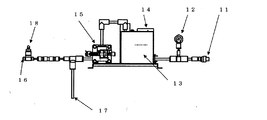
図1及び図2は、本発明を適用したマイクロ・ナノバルブ発生システムの正面図及びその斜視図であり、15がベローズシリンダポンプ、13がポンプコントローラ、14が気液混合槽、12が圧力センサ、11がマイクロ・ナノバルブ発生用ノズル取付部、17が液吸引管、16が気体吸引口、18が気体吸引調整バルブである。 1 and 2 are a front view and a perspective view of a micro / nanovalve generating system to which the present invention is applied, in which 15 is a bellows cylinder pump, 13 is a pump controller, 14 is a gas-liquid mixing tank, 12 is a pressure sensor, 11 is a nozzle mounting portion for generating a micro / nano valve, 17 is a liquid suction pipe, 16 is a gas suction port, and 18 is a gas suction adjustment valve.
これらは、図2に示す斜視図のように配置する。15の接液部をフッ素樹脂で作成したベローズシリンダポンプ15で17の液吸引管、18の気体吸引調整バルブを使用して気体量を調整してポンプ内部に液と気体を混ぜた状態で吸い込んでベローズ内部で撹拌、溶存させて、圧縮し液の中に気体を溶存させる。本発明においては、ベローズシリンダポンプ15はメタルフリーであれば良く、フッ素樹脂以外のプラスチック、例えば、、ポリエチレン、ポリプロピレン及びポリエチレンテレフタレート等の汎用プラスチック、ポリアセタール、ポリアミド、ポリカーボネート及び変性ポリフェニレンエーテル等のエンジニアリングプラスチック、ポリエーテルサルフォン、ポリフェニレンスルフィド、ポリエーテルエーテルケトン及び液晶ポリマー等のスーパーエンジニアリング等の少なくとも1種を使用しても良い。その場合、ポンプだけでなく、液設部にもフッ素樹脂を始め、前記の各種プラスチックを用いることによって、信頼性の高い清浄なマイクロ・ナノバブル発生装置とすることができる。また、本発明において、厳密なメタルフリー化による洗浄や殺菌が要求されない場合には、上記のプラスチックだけでなく、金属やセラミックスを使用しても良い。
These are arranged as in the perspective view shown in FIG. The
次に、気液混合槽14に気体と液をポンプ15で撹拌して圧送する。ポンプ15は、主に圧縮空気起動式ベローズシリンダポンプを使用するが、電動式のものであっても良い。気液混合槽14の気体と液とは、ポンプ15からの圧力を受けており、気体が溶存しやすくなる。つまり気体と液体とをポンプ15から圧送する圧力、この圧力は、12の圧力センサでチェックしている。この方法によって溶存気体の量を多くしてマイクロ・ナノバブルの発生量を増やす準備を行う。
Next, gas and liquid are stirred and pumped into the gas-
圧送されて気液混合槽14に入った液は気体と混合して、気体を液の内部に溶存させてからマイクロ・ナノバルブ発生用ノズル取り付け部11に送る。マイクロ・ナノバルブ発生用ノズル取り付け部11は、溶存した気体を直径が60μm以下、好ましくは15μm以下の大きさのマイクロ・ナノバルブを大量に作成するノズルと接続する部分である。
The liquid that has been pressure-fed and entered the gas-
このとき、12の圧力センサでノズル11と気液混合槽14との間の液圧力の変動をみて気液の溶存状態を監視する。こうすることで安定したマイクロ・ナノバルブ用発生ノズルに必要な一定した圧力状態を実現する。
At this time, the dissolved state of the gas-liquid is monitored by observing the fluctuation of the liquid pressure between the nozzle 11 and the gas-
図1及び図2に示す本発明を適用したマイクロ・ナノバルブ発生装置を用いて実施する工程は次の通りである。気体吸引口16、液吸引管17及び気体吸引調整バブル18を用いて行うのが気体・液体吸引工程である。圧力は、圧力センサ12で調整する。次に、ベローズシリンダポンプ15を用いて気体を含む液体を加圧する工程が気体・液体加圧工程である。引き続き、加圧された前記の気体を含む液体を新たな気体と混合させるために、ポンプコントローラ13及び気液混合槽14を用いて行う工程が溶存気体富化工程である。その後、後述する本発明の発生ノズルをマイクロ・ナノバルブ発生用ノズル取付部11に接続してからマイクロ・ナノバブルを発生させる。この工程を溶存気体微細化工程と呼ぶが、マイクロ・ナノバブルは、2以上の貫通小穴を有する筒の外部から該貫通小穴を通して大気圧以上の圧力で噴射し、前記筒の内部の一点で衝突させることによって発生させることができる。
The steps carried out using the micro / nanovalve generator to which the present invention shown in FIGS. 1 and 2 is applied are as follows. The gas / liquid suction step is performed using the
次に、気体が溶存した状態にある溶存液からマイクロ・ナノバルブを大量に発生させる方法について説明する。図3はマイクロ・ナノバルブ発生用ノズル取り付部の断面図で1、2がノズルの外ケース、ポンプで圧送された溶存液を2分割して、矢印で示すように1の外ケースと2の外ケースから対向するように配置し8のボルトと9のナットで固定する。このように配置した外ケースの中に掘り込みを作り3、4の高速ジェット液噴射ノズル発生部を取りつける。このノズルの穴の大きさで液の吐出流量、液流速を決める。 Next, a method for generating a large number of micro / nanovalves from a dissolved solution in which a gas is dissolved will be described. FIG. 3 is a cross-sectional view of the nozzle mounting portion for generating the micro / nanovalve. 1, 2 are the outer case of the nozzle, and the dissolved liquid pumped by the pump is divided into two parts, as shown by the arrows, It is arranged so as to face the outer case, and is fixed with 8 bolts and 9 nuts. A digging is made in the outer case arranged in this way, and three or four high-speed jet liquid jet nozzle generating portions are attached. The liquid discharge flow rate and liquid flow rate are determined by the size of the nozzle hole.
図4は、組立てられたノズルで8のボルトを9のナットで締め付け固定した状態を示している。マイクロ・ナノバブルを発生した水を矢印の円周方向に吐出する。図5は、高速ジェット液噴射ノズルの側面図であり、マイクロ・ナノバブル水は円周方向に吐出される。 FIG. 4 shows a state where 8 bolts are fastened and fixed by 9 nuts with the assembled nozzle. Water with micro / nano bubbles is discharged in the circumferential direction of the arrow. Figure 5 is a side view of a high-speed jet liquid jet nozzle, micro-nano bubble water is discharged in the circumferential direction.
この高速ジェット液噴射ノズルからの水流を用いてマイクロ・ナノバルブを作成する方法について説明する。高速ジェット液噴射ノズルから出た高圧ポンプ15の吐出圧力(0.2MPa〜0.6MPa)状態から圧力を急激に解放するので気体が溶存する液が互いに激突し、その水撃力で炸裂する力で気体を溶存した液を砕いてマイクロ・ナノバルブを大量に含む状態にする。ただし解放する方法によっては、マイクロ・ナノバブルの発生量が少なくなってしまう場合があるが、本発明による方法と装置によってマイクロ・ナノバブルを大量に発生させることができる。
A method of creating a micro / nanovalve using the water flow from the high-speed jet liquid injection nozzle will be described. Since the pressure is abruptly released from the discharge pressure (0.2 MPa to 0.6 MPa) state of the high-
図6は、マイクロ・ナノバブルを発生させるノズルの3、4の高速ジェット液噴射ノズル発生部の断面図B−Bと外形図である。3、4の高速ジェット液噴射のノズル発生部は、断面図に示すように中心を決める5のセンターピンでセンター出しを行い6と7の位置決めピンで位置合わせをして固定する。この3,4の高速ジェット液噴射ノズル発生部がマイクロ・ナノバブルを発生させる。
6A and 6B are a cross-sectional view BB and an external view of the
図7は、図6の3と4の高速ジェット液噴射ノズル発生部の拡大した断面図であり、3と4は、同じ形で対称に配置されているので3、4の符号で説明する。3、4に気体を溶存させた液を高速ジェトにして送るために3a、4aの流路用小穴で絞る。この絞った流路用小穴3a、4aの先からジェット流が飛び出して3と4の各高速ジェット液噴射ノズル発生部から出たジェットが激突するようにノズル部3b、4bを配置し、激突した気体溶存液からマイクロ・ナノバブルを作成する。ここでできた気体を内部に包み込んだマイクロ・ナノバブルが矢印の円周方向に拡散する。
FIG. 7 is an enlarged cross-sectional view of the high-speed jet liquid jet
高圧で液を送る理由は、小さい穴から出る液の速度を早くすることが目的である。つまり高速で液を衝突させることで、衝撃エネルギーが大きくなり、より大量で小さいマイクロ・ナノバブルを発生させることができる。 The reason for sending the liquid at high pressure is to increase the speed of the liquid coming out of the small hole. In other words, impact energy is increased by colliding liquid at high speed, and a larger amount of small micro / nano bubbles can be generated.
Fが衝突する力とする。液の密度ρ、Sを小さい穴の大きさ、液の速度をVとする。F=ρSV2の関係が成り立つ。Fを最適値にするためには、穴の大きさSと速度Vの関係を考慮した最適設計が必要になる。 The force with which F collides. Let the density ρ and S of the liquid be the size of a small hole and the speed of the liquid be V. The relationship F = ρSV 2 is established. In order to set F to an optimum value, an optimum design is required in consideration of the relationship between the hole size S and the speed V.
ここで重要なことは、もっと高圧を作るポンプの場合には、より多くのマイクロ・ナノバブルを発生させることができる可能性がある。例えば、0.5MPa〜250MPaなどという高圧ポンプもあり、そのようなポンプを使う場合は、圧力に比例し液流速Vが増し、Vの2乗で水撃力Fが増加するのでマイクロ・ナノバブルの発生量は、格段にUPする。しかしながら、そのような高圧のポンプをマイクロ・ナノバブル発生装置に適用することは、軽量、小型、メタルフリー及び低い維持費等の各種要求を満たすことが困難である。 What is important here is that in the case of a pump that produces higher pressures, more micro-nano bubbles may be generated. For example, there are high pressure pumps of 0.5 MPa to 250 MPa, etc., and when such a pump is used, the liquid flow velocity V increases in proportion to the pressure, and the water hammer F increases with the square of V. The amount generated is significantly increased. However, applying such a high-pressure pump to a micro / nano bubble generator is difficult to satisfy various requirements such as light weight, small size, metal free and low maintenance cost.
本発明は、図3〜図7に示すような構造を有するノズルを使用することによって、気液混合の状態にある溶存液を噴射するときの圧力が大気圧(約0.1Mpa)以上であれば、マイクロ・ナノバブルの発生量を従来と同等以上にすることができる。さらに、この圧力を0.2Mpa以上に設定することによって、清浄な洗浄・殺菌を行うための十分な量のマイクロ・ナノバブルを発生させることができる。このように、本発明においては溶存液の噴射圧力の下限値を0.2Mpaと従来よりも低くできるため、金属コンタミの影響を無くすために好適なポンプ、すなわち、図1及び図2に示すようなフッ素樹脂で作製した圧縮空気駆動式又は電動式のベローズシリンダポンプ15を使用することが可能となる。また、本発明の圧縮空気駆動式又は電動式のベローズシリンダポンプを使用するとき、溶存液の噴射圧力が0.6MPaを超えると、マイクロ・ナノバブルの発生量は飽和する傾向にある。したがって、本発明において溶存液を噴射するときの圧力は、0.2〜0.6MPaが好ましい。
The present invention uses a nozzle having a structure as shown in FIGS. 3 to 7 so that the pressure when injecting the dissolved liquid in a gas-liquid mixed state is at least atmospheric pressure (about 0.1 Mpa). For example, the generation amount of micro / nano bubbles can be made equal to or higher than the conventional one. Furthermore, by setting this pressure to 0.2 Mpa or more, it is possible to generate a sufficient amount of micro / nano bubbles for performing clean cleaning and sterilization. Thus, in the present invention, since the lower limit value of the injection pressure of the dissolved liquid can be lowered to 0.2 Mpa as compared with the conventional one, a pump suitable for eliminating the influence of metal contamination, that is, as shown in FIG. 1 and FIG. It is possible to use a compressed air driven or electric
本発明のマイクロ・バブル発生ノズルは、大気圧以上、好ましくは0.2〜0.6MPaという従来よりも低い圧力で溶存液のジェット流を噴射できるようにするため、図7の3b、4bで示すノズル部は径が0.1〜6.0mmであることが必要である。ここで、ノズル部3b、4bのジェット流が飛び出す口及びノズル部3b、4bの径が、本発明において定義する「出射口」及び「ノズルの貫通小穴が筒の空洞に通じる部分の孔径」に相当するものである。なお、ノズル部3b、4bの径を0.1〜6.0mmに規定する理由については、後述の実施形態で詳細に説明する。 The micro-bubble generating nozzle of the present invention is capable of injecting a jet of dissolved liquid at a pressure higher than atmospheric pressure, preferably 0.2 to 0.6 MPa. The nozzle part shown needs to have a diameter of 0.1 to 6.0 mm. Here, the diameter of the nozzle part 3b, 4b from which the jet flow jumps out and the diameter of the nozzle part 3b, 4b are defined as "the exit port" and "the hole diameter of the part where the through hole of the nozzle communicates with the hollow of the cylinder". It is equivalent. In addition, the reason for prescribing the diameters of the nozzle portions 3b and 4b to 0.1 to 6.0 mm will be described in detail in an embodiment described later.
図7において、流路用小穴3a、4aは、気体を溶存させた液を高速ジェトにして送るための絞り機能を有するものであればよく、ノズル部3b、4bに向かって連続的にテーパー状で形成されていても良い。マイクロ・ナノバブルの発生量は、主にノズル部3b、4bの径によって決まるものであり、本発明においては流路用小穴3a、4aの部分を省略することもできる。 In FIG. 7, the small holes 3a and 4a for the flow path need only have a throttling function for sending the liquid in which the gas is dissolved as a high-speed jet, and are continuously tapered toward the nozzle portions 3b and 4b. It may be formed by. The generation amount of micro / nano bubbles is mainly determined by the diameters of the nozzle portions 3b and 4b. In the present invention, the portions of the small holes 3a and 4a for the flow path can be omitted.
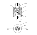
気体溶存した液を激突させる別の方法についての事例を、図8を用いて説明する。図8は、マイクロ・ナノバブルを発生させるノズルで、ノズルケース21と、マイクロ・ナノバブル吐出ノズル22と、台24とから構成されており、液衝突ノズル23の1個又は2個以上を24の台上に取り付け配置する。
An example of another method for causing a gas-dissolved liquid to collide will be described with reference to FIG. FIG. 8 shows a nozzle for generating micro / nano bubbles, which includes a
図9は、図8に示す23の液衝突ノズルを配置した部分の拡大図である。図10は23の液衝突ノズルの1個の形状を示している。23aの小さな穴は23の中心に向かって空いている。この小さな穴から矢印Pから高圧で入った液がこの小さな穴を通って23の中心の部分で衝突させてマイクロ・ナノバブル発生させる。 FIG. 9 is an enlarged view of a portion where 23 liquid collision nozzles shown in FIG. 8 are arranged. FIG. 10 shows the shape of one of the 23 liquid collision nozzles. The small hole 23a is open toward the center of 23. From this small hole, the liquid entered at high pressure from the arrow P passes through this small hole and collides with the central portion of 23 to generate micro / nano bubbles.
実験の結果、液の速度Vをコントロールすれば、発生したマイクロ・ナノバブルの量が多く、かつバブルの寿命が長くなることがわかった。速度Vの目安として、25m/秒を超える速度になると安定したマイクロ・ナノバブル発生ノズルになる。 As a result of the experiment, it was found that if the liquid velocity V was controlled, the amount of micro / nano bubbles generated was increased and the lifetime of the bubbles was prolonged. As a measure of the speed V, when the speed exceeds 25 m / sec, a stable micro / nano bubble generating nozzle is obtained.
同じ効果は、四方から中心に向けて発射してセンターに水撃を集中させることで速度を落としても得られる。つまり、四方からの水撃の場合には、1/2の速さでも同じか、又はそれ以上の効果になる。例えば、F=2ρSV2なので8個の穴があり中心に集中する場合は、中心に集まる力F=ρS(1/2)2×8=2ρSV2になる。このように液が衝突して中心に水撃を集中させるのにノズルの小さい穴を複数にすると、速度Vが遅くとも、流量が多くなるため液の衝突するエネルギーが同じになる。マイクロ・ナノバブルの発生量は液の衝突するエネルギーが同じであれば良いということなので、液を吐出する圧力も下げられ、かつ発生するマイクロ・ナノバブルの量を確保できる。 The same effect can be achieved by reducing the speed by launching from all directions to the center and concentrating the water hammer at the center. That is, in the case of water hammer from four directions, the effect is the same or more even at a speed of 1/2. For example, if F = 2ρSV 2 and there are 8 holes and they are concentrated at the center, the force gathered at the center is F = ρS (1/2) 2 × 8 = 2ρSV 2 . In this way, when the liquid collides and the water hammer is concentrated at the center, if a plurality of small holes are formed in the nozzle, even if the speed V is low, the flow rate increases so that the energy with which the liquid collides is the same. Since the generation amount of micro / nano bubbles is sufficient as long as the energy of collision of the liquid is the same, the pressure for discharging the liquid can be lowered and the amount of generated micro / nano bubbles can be secured.
図10は、23の液衝突ノズルの形状で23のノズル筒の部分の周の部分に小穴23aを空けて、この穴を通して溶存液の中心位置での衝突によってマイクロ・ナノバブルが発生する。ここで発生したマイクロ・ナノバブルは、Qの矢印の方向に吐出して、多数個の液衝突ノズル23を集積するとマイクロ・ナノバブルが大量に出て、図8に示す吐出ノズル22の22aのノズル部から吐出する。
Figure 10 is spaced small holes 23 a in the circumferential portion of the portion of 23 nozzles barrel in the form of
図11に示すように、液衝突ノズル25の形状は、25aの小穴を多段に空け、例えば3段に穴をあけて液の水撃の発生する場所を3ヵ所にすることでマイクロ・ナノバブルを大量に発生させることが可能になるので、ノズルの小型化と効率化には有効な方法である。
As shown in FIG. 11, the shape of the
図11に示すノズルのように、複数の穴から液を吐出させることで、水撃の強度を増加させることができる。この技術を使うと、液の速度Vが遅くてもマイクロ・ナノバブルの発生量が減少しないので、高圧で液を吐出させるポンプが必要でなくなり、負担が少なくて済むため、工業的には、非常に有益な技術で、エネルギー効率の良いノズルの開発ができる。 Like the nozzle shown in FIG. 11, the strength of water hammer can be increased by discharging liquid from a plurality of holes. If this technology is used, the amount of micro / nano bubbles generated does not decrease even if the liquid velocity V is low, so there is no need for a pump that discharges liquid at a high pressure, and the burden can be reduced. This makes it possible to develop energy-efficient nozzles that are very useful.
図12は、気液混合槽14の断面図である。また、図13には、図12において円で囲った領域Eの拡大図を示す。従来の気液混合槽は、気体と液体を高圧で混合するが、ポンプで気体と純水を混合して送る際、気液混合槽内部では、上部に噴水のように噴射して混合する方法で行っていた。しかし、この方法は混合の効率が悪いので効率を良くするために、マイクロ・ナノバブル発生量を多くすることが必要である。
FIG. 12 is a cross-sectional view of the gas-
そこで、図12に示すように、ポンプから気体と液体とを矢印Aから矢印Bへ、次に32と33の気液挿入パイプに気体と液を送り、図13に示すように、気液挿入パイプ32aの穴と33の気液挿入パイプの33aの穴から吐出する気液混合の効率を上げるために液を矢印X方向からと矢印Y方向から衝突させることで起こる水撃を利用することによって、気体と液体との混合を効率よく行い、マイクロ・ナノバブルの原料になる気液混合液を早くかつ混合率も上げることができる。
Therefore, as shown in FIG. 12, the gas and the liquid are sent from the pump from the arrow A to the arrow B, and then the gas and the liquid are sent to the gas and
図12に示す31のフロートは、気液混合するときに気体が多く入りすぎたときに余分に入り過ぎた気体を外部に排出することを目的にして配置したもので、余分に入った気体を安全に排出し、気体と液体の量を適正にする働きをする。つまり気体が余分に入り過ぎて気体のままで残存したときにノズルに気体が流れ込んでしまいマイクロ・ナノバブルの発生ができなくなり、マイクロ・ナノバブル発生が阻害される弊害をなくすことでマイクロ・ナノバブルの発生量を適正かつ安定的に送ることができる。
The
図14には、図12のフロート31の部分の断面図を示している。この31のフロート管の構造は31aのフロート先端部(尖り先にしてある)とフロートが液の圧力で潰れないようにする31bの補強リブと31Cの止め栓とで構成する。
FIG. 14 shows a cross-sectional view of a portion of the
液と気体を混合するには、気体と液の接触面積を大きくすることで気体が液内に溶存する効率を上げることが気液混合に必要であり、この効率が落ちるとマイクロ・ナノバブルの発生にとって致命的な気体不足による発生量の不足になる。 In order to mix liquid and gas, it is necessary for gas-liquid mixing to increase the gas-liquid contact area to increase the efficiency of the gas dissolved in the liquid. The amount of generated gas will be insufficient due to the fatal gas shortage.
液体と気体の量をどの程度でコントロールすると発生するマイクロ・ナノバブルが多くなるかの検討を行った結果、液の量が気液混合槽内の体積比で液が6割、気体が4割が理想的なバランスであり、両者の比率を自動的にコントロールする目的で、この31のフロートの液による浮力を使用して、フロート受け47の過剰ガス排出口48から、余剰気体の排出を行い自動調整を行うことで溶存する気体と液の混合を最適化し、マイクロ・ナノバブルの発生量を安定化させ、マイクロ・ナノバブルの発生量を多くすることが必要である。本発明においては、マイクロ・ナノバブルの発生量を大量にするために、気液混合槽内の液と気体の体積比を液:気体=50:50〜95:5の範囲内で、液の体積比が大きくなるようにコントロールすることが好ましい。本発明において、フロート31は気液混合槽の内部だけでなく、外部に設置してもよい。その場合、気液混合槽の内部と外部とを連結管等によって接続すれば、内部に存在する液と気体の体積比をコントロールすることができる。
As a result of investigating how much the amount of micro / nano bubbles generated by controlling the amount of liquid and gas increases, the amount of liquid is 60% of the liquid and 40% of the gas by the volume ratio in the gas-liquid mixing tank. For the purpose of automatically controlling the ratio of the two in an ideal balance, the surplus gas is automatically discharged from the excess
図15は、気液混合槽をより効率UPしたものにするために実施したものである。基本動作は、図12と図13とで示した内容と同じであり、36、38、40で構成した気液混合槽を基本にし気液混合槽の内部圧力に耐える構造を持たせたものの中で効率良く気体と液体を混合することにある。 FIG. 15 is carried out to make the gas-liquid mixing tank more efficient. The basic operation is the same as that shown in FIG. 12 and FIG. 13, and is based on the gas-liquid mixing tank composed of 36, 38, 40, and has a structure that can withstand the internal pressure of the gas-liquid mixing tank. It is to mix gas and liquid efficiently.
図15に示す気液混合外枠36、フロート41、フロートホルダー35、35aは、フロートホルダー過剰ガス排出口であり、フロート41の41aのフロートの先端で過剰気体を自動調整する機能を有する。
Gas-liquid mixing outside the
従来マイクロ・ナノバブルの発生量が少ない装置の場合、一回水槽などにマイクロ・ナノバブルを発生させておき、この水槽内にできたマイクロ・ナノバブルをポンプで再度汲み上げて気液混合槽で溶存気体を追加投入し、何度も繰り返し循環させマイクロ・ナノバブルを大量に含んだものにするという方法でマイクロ・ナノバブル発生させるものが主流であった。 In the case of a device that generates a small amount of micro / nano bubbles in the past, micro / nano bubbles are generated once in a water tank, and the micro / nano bubbles generated in the water tank are pumped up again with a pump, and dissolved gas is generated in a gas-liquid mixing tank. The mainstream was the generation of micro / nano bubbles by a method in which they were additionally introduced and circulated over and over again to contain a large amount of micro / nano bubbles.
この方法では、マイクロ・ナノバブルの量の管理が困難になり、さらに、循環を行うとコンタミが発生するなどの不具合が発生する。そのため、循環を使わないで、1回の動作でマイクロ・ナノバブルを大量に発生させることができる装置を望まれている。 This method makes it difficult to control the amount of micro / nano bubbles, and further causes problems such as contamination when the circulation is performed. Therefore, there is a demand for an apparatus that can generate a large number of micro / nano bubbles in one operation without using circulation.
そこで、本発明で使用する気液混合槽の中に、図8に示すものと同じ構造を有するノズルホルダー39に保持されるマイクロ・ナノバブル発生ノズル38の働きで、気液混合の状態で液衝突によって、循環なしでマイクロ・ナノバブルを発生させる。
Therefore, in the gas-liquid mixing tank used in the present invention, the liquid collision occurs in the gas-liquid mixing state by the action of the micro / nano
その場合、気液混合槽内部に配置したノズル38は、気液混合槽内で圧力を上げるために、先端に配したノズル11よりも気液混合状態の溶存液の流量が多いことが必須条件である。もしもこのノズル38の方の流量が少ない場合には、先端に付けたノズルからマイクロ・ナノバブルが発生しないことがある。
In that case, in order to raise the pressure in the gas-liquid mixing tank, the
このノズル38を気液混合槽に入れた効果は、この気液混合槽とノズル1回のパスで大量のマイクロ・ナノバブルを安定して発生させることができる。それによって、例えば、半導体製造の洗浄に最適なマイクロ・ナノバブル発生装置を提供できる。
The effect of placing the
本発明においては、この気液混合槽を多段にセットすることで、より多くのマイクロ・ナノバブルを発生させることができ、大量のバブルを発生させるための有効な手段になる。 In the present invention, by setting the gas-liquid mixing tank in multiple stages, more micro / nano bubbles can be generated, which is an effective means for generating a large number of bubbles.
図16は、マイクロ・ナノバブルを発生させるノズルの別の方法を提案する。つまり小穴ノズル45の2以上を取り付けるのに、溶存液の流入又は吐出の方向(長手方向)に対して垂直に並べる配置を採用する。これは、平行に並べた図8に示すものとは異なる配置である。図16に示すように配置すると42、43の外ケースと46のパッキンと44のノズルホルダーに小穴のノズルを図のように配置することで小穴のノズルは、両側に吐出口ができるので流量を確保することが楽にできるという利点がある。
FIG. 16 proposes another nozzle method for generating micro-nano bubbles. That is, in order to attach two or more of the
図16において、INから入れた気液混合液は、45のノズルで水撃状態になりマイクロ・ナノバブルを発生させた後にノズルの両側に出るので流量確保ができるのと、効率が倍になるのでマイクロ・ナノバブルを作るエネルギーが半分になる。 In FIG. 16, the gas-liquid mixed solution put in from IN is in a water hammer state with 45 nozzles and is generated on both sides of the nozzle after generating micro / nano bubbles, so the flow rate can be secured and the efficiency is doubled. The energy to create micro / nano bubbles is halved.
このような水撃法によって作られるノズルは、液同士が衝突するのでノズル構造部へのダメージが少なく寿命の長い発生装置に仕上げることができる。 A nozzle made by such a water hammer method can be finished into a generator having a long life because liquids collide with each other and damage to the nozzle structure is small.
本発明のマイクロ・ナノバブルの発生方法及び発生装置は、半導体や食品等の洗浄・殺菌への適用を図るために、溶存液として核剤等の不純物が混入されていない純水を使用できることが大きな特徴である。仮に、マイクロ・ナノバブルの発生量を増やすために核剤等の使用が必要になる場合でも、その純水中への混入量を大幅に低減することができる。本発明においては、純水以外にも、供給状態や使い易さ等を考慮して、例えば、水道水、井戸水又は天然水等の湧水を使用することができる。さらに、本発明においては、洗浄・殺菌効果を上げるために、溶存液を酸化作用を強くしたり、不純物の剥離浸透性を高めた液に改質しても良い。 The micro / nano bubble generation method and generator of the present invention can use pure water in which impurities such as a nucleating agent are not mixed as a dissolved liquid in order to be applied to cleaning and sterilization of semiconductors and foods. It is a feature. Even if it is necessary to use a nucleating agent or the like in order to increase the amount of micro / nano bubbles generated, the amount mixed in pure water can be greatly reduced. In the present invention, in addition to pure water, for example, spring water such as tap water, well water or natural water can be used in consideration of the supply state and ease of use. Furthermore, in the present invention, in order to improve the cleaning and sterilizing effect, the dissolved liquid may be modified to a liquid that has a stronger oxidizing action or an improved impurity penetration permeability.
上記の溶存液を酸化作用を強くする方法としては、純水にオゾン、酸素、過酸化水素、塩素酸、過塩素酸及び過マンガン酸カリウムからなる群の少なくとも1つを混入させて、これら酸化剤の少なくとも1つを有する水溶液とする方法である。これらの酸化剤の中で、オゾン及び酸素は添加成分としての悪影響がほとんどなく、環境への負荷も非常に小さいことから、本発明においてより好ましい。 As a method for strengthening the oxidizing action of the above-mentioned dissolved liquid, pure water is mixed with at least one of the group consisting of ozone, oxygen, hydrogen peroxide, chloric acid, perchloric acid and potassium permanganate, and the oxidation is performed. This is a method of preparing an aqueous solution having at least one agent. Among these oxidizing agents, ozone and oxygen are more preferable in the present invention because they have almost no adverse effects as additive components and have a very small environmental load.
上記の不純物の剥離浸透性を高める方法としては、炭酸ガス、水素ガス又は窒素ガスの剥離浸透性に優れる気体を混入させる方法が好ましい。炭酸ガス、水素ガス又は窒素ガスは、マイクロ・ナノバブルの発生によって、例えば半導体素子とその表面に付着したレジスト残り等の不純物との界面に容易に侵入するため、洗浄効果を大幅に高めることができる。さらに、炭酸ガス又は窒素ガスは人体に無害であるので、本発明で使用する溶存液の改質剤として好適である。 As a method for increasing the peel permeability of the impurities, a method of mixing a gas excellent in the peel permeability of carbon dioxide gas, hydrogen gas or nitrogen gas is preferable. Carbon dioxide gas, hydrogen gas, or nitrogen gas can easily enter the interface between the semiconductor element and impurities such as resist residue attached to the surface due to the generation of micro / nano bubbles, so that the cleaning effect can be greatly enhanced. . Furthermore, since carbon dioxide gas or nitrogen gas is harmless to the human body, it is suitable as a modifier for the dissolved liquid used in the present invention.
本発明のマイクロ・ナノバブルを発生させるノズルの構造と形状について、具体的な実施形態を用いて詳しく説明する。 The structure and shape of the nozzle for generating micro / nano bubbles of the present invention will be described in detail using specific embodiments.
[第1の実施形態]
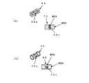
水撃力を利用してマイクロ・ナノバブルを発生させるために検討した液衝突ノズルの構造と形状を図17に示す。図17の(a)は本発明の実施形態に対して比較例に相当するものであり、図17の(b)〜(d)が本発明による実施形態である。
[First Embodiment]
FIG. 17 shows the structure and shape of a liquid collision nozzle studied for generating micro / nano bubbles using water hammer force. FIG. 17A corresponds to a comparative example with respect to the embodiment of the present invention, and FIGS. 17B to 17D show the embodiment according to the present invention.
図17の(a)は、空洞の筒の周囲に1穴49aを形成したものであり、貫通小孔として1穴49aを有するこの比較例の場合には、液の速度Vで出た溶存した液が49の管の壁に直接衝突させる方法になるので発生するマイクロ・ナノバブルは少なく、かつ壁にぶつかるので液の衝撃で壁が破壊される欠点がある。 FIG. 17A shows a case in which one hole 49a is formed around a hollow cylinder, and in the case of this comparative example having one hole 49a as a small through hole, the solution discharged at a liquid velocity V was dissolved. Since the liquid directly collides with the wall of 49 tubes, there are few micro / nano bubbles generated, and the wall is destroyed by the impact of the liquid because it hits the wall.
図17の(b)に示す液衝突ノズルは、貫通小孔として2穴50aが形成されており、この実施形態においては、液の速度Vで出た溶存した液を衝突させると対抗した位置に50aが配置されているため、2Vの速度での衝突が実現できる。衝突のエネルギーは、図17の(a)の比較例と比べて高くなる。 The liquid collision nozzle shown in FIG. 17 (b) is formed with two holes 50a as through-holes. In this embodiment, the liquid collision nozzle is located at a position opposed to the collision of the dissolved liquid discharged at the liquid velocity V. Since 50a is arranged, a collision at a speed of 2V can be realized. The energy of the collision is higher than that in the comparative example of FIG.
図17の(c)に示す液衝突ノズルは、貫通小孔として3穴51aが形成されており、この実施形態においては、液の速度Vで出た溶存した液を衝突させるのに120度の位置に3個の穴を開けることによって、Vの速度で出た液は、中心の激突する点でのエネルギーが3倍になる。つまり3個の穴を利用して衝突させた場合には、先の2個の穴と同じエネルギーで良いのであれば速度Vを20%落としても同じエネルギーになる。速度Vがポンプの圧力で決まるので圧力をさげてもマイクロ・ナノバブルを発生させることができる。 The liquid collision nozzle shown in FIG. 17 (c) is formed with three holes 51a as through-holes. In this embodiment, the liquid collision nozzle of 120 degrees is used to collide the dissolved liquid discharged at the liquid velocity V. By drilling three holes in the position, the liquid that comes out at the speed of V triples the energy at the center clash. That is, when the collision is made using three holes, the same energy can be obtained even if the speed V is reduced by 20% if the same energy as that of the previous two holes is sufficient. Since the speed V is determined by the pressure of the pump, micro / nano bubbles can be generated even if the pressure is reduced.
図17の(d)に示す液衝突ノズルは、貫通小孔として4穴52aが形成されており、この実施形態においては、液の速度Vで出た溶存した液を衝突させるのに90度の位置に4個の穴を開けることによって、Vの速度で出た液は、中心の激突する点でのエネルギーが4倍になる。つまり4個の穴を利用して衝突させた場合には、先の2個の穴と同じエネルギーで良いのであれば速度Vを30%落としても同じエネルギーになる。速度Vがポンプの圧力で決まるので圧力をさげてもマイクロ・ナノバブルを発生させることができる。 The liquid collision nozzle shown in FIG. 17D is formed with four holes 52a as small through holes. In this embodiment, the liquid collision nozzle of 90 degrees is used to collide the dissolved liquid discharged at the liquid velocity V. By drilling four holes in the position, the liquid coming out at the speed of V is quadrupled in energy at the center clash. That is, when collision is performed using four holes, if the same energy as that of the previous two holes is sufficient, the same energy can be obtained even if the speed V is reduced by 30%. Since the speed V is determined by the pressure of the pump, micro / nano bubbles can be generated even if the pressure is reduced.
図17の(e)に示す液衝突ノズルは、貫通小孔として5穴53aが形成されており、この実施形態においては、液の速度Vで出た溶存した液を衝突させるのに72度の位置に5個の穴を開けることによって、Vの速度で出た液は、中心の激突する点でのエネルギーが5倍になる。つまり5個の穴を利用して衝突させた場合には、先の2個の穴と同じエネルギーで良いのであれば速度Vを40%落としても同じエネルギーになる。速度Vがポンプの圧力で決まるので圧力をさげてもマイクロ・ナノバブルを発生させることができる。 The liquid collision nozzle shown in FIG. 17 (e) is formed with five holes 53a as through-holes. In this embodiment, the liquid collision nozzle of 72 degrees is used to collide the dissolved liquid discharged at the liquid velocity V. By drilling 5 holes in the position, the liquid that comes out at the speed of V becomes 5 times the energy at the collision point of the center. That is, when the collision is made using five holes, the same energy can be obtained even if the speed V is decreased by 40% if the same energy as the previous two holes is sufficient. Since the speed V is determined by the pressure of the pump, micro / nano bubbles can be generated even if the pressure is reduced.
以上のように、液衝突ノズルの貫通小孔の構造と配置を最適化することによって高圧ポンプを利用しないと作ることができなかったマイクロ・ナノバブルがポンプ圧力を0.2Mpaにしても大量に発生させることができるので、省エネが実現できる。 As described above, micro / nano bubbles that could not be created without using a high-pressure pump by optimizing the structure and arrangement of the through-holes of the liquid collision nozzle are generated in large quantities even when the pump pressure is 0.2 MPa. Energy saving can be realized.
[第2の実施形態]
本発明のマイクロ・ナノバブルを発生させる液衝突ノズルにおいて、空洞を有する筒の端部に設けるマイクロ・ナノバブル吐出口の径と、貫通小孔が周方向に配置される部分の筒の径との関係について図18を用いて説明する。
[Second Embodiment]
In the liquid collision nozzle for generating micro / nano bubbles of the present invention, the relationship between the diameter of the micro / nano bubble discharge port provided at the end of the hollow cylinder and the diameter of the cylinder at the portion where the through small holes are arranged in the circumferential direction Will be described with reference to FIG.
図18の(a)に、穴54aを2つ有する液衝突ノズルを示す。54のノズルの筒において噴射液が衝突する部分(貫通小孔が形成されている部分)の径をD1と太くし、吐出口の径をD2と細くすることで液衝突でできたマイクロ・ナノバブルに直ぐに圧力がかかる。このことでマイクロ・ナノバブルの組成をコントロールすることができる。つまり発生したマイクロ・ナノバブルの粒子分布をコントロールする手段になり、粒子の微細化に効果がある。 FIG. 18A shows a liquid collision nozzle having two holes 54a. Micro / nanobubbles formed by liquid collision by increasing the diameter of the portion where the jetting liquid collides (the portion where the through hole is formed) to D1 and the diameter of the discharge port to D2 in the cylinder of 54 nozzles. Immediate pressure is applied. This makes it possible to control the composition of micro / nano bubbles. In other words, it becomes a means for controlling the particle distribution of the generated micro / nano bubbles, and is effective in making the particles finer.
図18の(b)に示す液衝突ノズルは、穴55aを2つ有するもので、55のノズルの筒において噴射液が衝突する部分の径をD3と細くし、吐出口の径をD4と太くする。このようにすると衝突でできたマイクロ・ナノバブルは、圧力がかからないので発生したら膨張するマイクロ・ナノバブルの粒子分布は、若干大きくなる。 The liquid collision nozzle shown in FIG. 18 (b) has two holes 55a. The diameter of the portion of the 55 nozzle cylinder where the spray liquid collides is reduced to D3, and the diameter of the discharge port is increased to D4. To do. In this way, since the micro / nano bubbles generated by the collision are not applied with pressure, the particle distribution of the micro / nano bubbles that expand when they are generated becomes slightly larger.
本発明においては図18に示す構造を有するノズルのどちらも使用することができるが、図18の(a)は、吐出口の径がノズルの筒において衝突する部分の径よりも細くなっているため、突出口近くの溶存液の圧力が高くなる。そのため、マイクロ・ナノバブル粒子の微細化には効果があるものの、バブルの生成がやや阻害されて、バブルの発生量の低下やバブルが突出口から離れた場所で時間的に遅れて発生するような現象が現れる場合がある。一方、図18の(b)に示す構造を有するノズルは、吐出口において圧力開放があるため、バブルを安定的に大量に発生させることができる。マイクロ・ナノバブルの微細化はノズルの貫通小孔の径によって調整することが可能であることから、本発明において図18の(b)に示すノズルが好適である。 In the present invention, either of the nozzles having the structure shown in FIG. 18 can be used. However, in FIG. 18A, the diameter of the discharge port is smaller than the diameter of the colliding part in the nozzle cylinder. For this reason, the pressure of the dissolved liquid near the protrusion is increased. Therefore, although it is effective for miniaturization of micro / nano bubble particles, the generation of bubbles is somewhat hindered, and the generation amount of bubbles is reduced or the bubbles are generated with a delay in time away from the protruding opening. A phenomenon may appear. On the other hand, the nozzle having the structure shown in FIG. 18B is capable of generating a large amount of bubbles stably because the pressure is released at the discharge port. Since miniaturization of the micro / nano bubble can be adjusted by the diameter of the through hole of the nozzle, the nozzle shown in FIG. 18B is suitable in the present invention.
[第3の実施形態]
図18の(b)に示す液衝突ノズルについて、液の圧力を一定にして、オゾン(50ppm)を含有する純水を溶存液として用いたときの衝撃ノズル径とマイクロ・ナノバブルとの関係を図19〜図21を用いて説明する。
[Third Embodiment]
For the liquid collision nozzle shown in FIG. 18 (b), the relationship between the impact nozzle diameter and the micro / nano bubbles when the liquid pressure is constant and pure water containing ozone (50 ppm ) is used as the dissolved liquid. This will be described with reference to FIGS.
図19は、ノズル56の貫通小孔から噴射する流量と吐出口から排出する流量との関係を示す図である。図19において、ノズル56の貫通小孔56aからV1の速度で噴射する溶存液は、一秒間に1穴56aから液量Q1で吐出した後、衝突してマイクロ・ナノバブルを発生させる。その後、V2の速度で56の管の吐出口から一秒間に液量Q2で出ていく。ここで、流量Q1とQ2は同じ値になる。 FIG. 19 is a diagram showing the relationship between the flow rate ejected from the through hole of the nozzle 56 and the flow rate discharged from the discharge port. In FIG. 19, the dissolved liquid sprayed from the through small hole 56a of the nozzle 56 at a speed of V1 is ejected at a liquid amount Q1 from one hole 56a per second, and then collides to generate micro / nano bubbles. Thereafter, the liquid Q2 is discharged from the discharge port of the 56 pipe at a speed of V2 with a liquid amount Q2 per second. Here, the flow rates Q1 and Q2 have the same value.
図20に、液衝突ノズルの貫通小孔の径とマイクロ・ナノバブルの発生量との関係を示す。ここで、マイクロ・ナノバブルの発生量は溶存液の単位体積当たりのバブル発生数でプロットした。図20において、液衝突ノズルの貫通小孔の径が大きくなると、V1が小さくなり液量Q1が多くなる。その場合は、マイクロバブル(60ミクロン以上)の発生量は増すが、ナノバブルの発生量が少なくなる。一方、熱衝突ノズルの貫通小孔の径が小さくなると、液量Q1が少なくなる。その場合は、マイクロバブル(60ミクロン以上)の発生が少なくなり、V1が大きくなるが、ナノバブル(2ミクロン以下)の発生量が増加する。 FIG. 20 shows the relationship between the diameter of the through hole of the liquid collision nozzle and the amount of micro / nano bubbles generated. Here, the amount of micro / nano bubbles generated was plotted as the number of bubbles generated per unit volume of the dissolved liquid. In FIG. 20, when the diameter of the through hole of the liquid collision nozzle increases, V1 decreases and the liquid amount Q1 increases. In that case, the generation amount of microbubbles (60 microns or more) increases, but the generation amount of nanobubbles decreases. On the other hand, when the diameter of the through hole of the thermal collision nozzle is reduced, the liquid amount Q1 is reduced. In that case, the generation of microbubbles (60 microns or more) decreases and V1 increases, but the generation amount of nanobubbles (2 microns or less) increases.
このように、液衝突ノズルの貫通小孔の径がマイクロ・ナノバブルの性能を決める重要な要素になっている。液と溶存させる気体の性質による違いもあるが、傾向は上記で説明したようになるので、液衝突ノズルの貫通小孔径によりマイクロ・ナノバブルの量をコントロールできる。 Thus, the diameter of the through hole of the liquid collision nozzle is an important factor that determines the performance of the micro / nano bubble. Although there are differences depending on the nature of the gas to be dissolved with the liquid, since the tendency is as described above, the amount of micro / nano bubbles can be controlled by the through-hole diameter of the liquid collision nozzle.
図21に、液衝突ノズルの貫通小孔径と流量Qとの関係を示す。液の圧力を一定にした状態で、1つの液衝突ノズルの貫通小孔径と流量Qとの関係は、液衝突ノズル径の2乗に比例するが、液の速度Vが液衝突ノズル径の2乗に反比例するので、図20に示したようになる。この液衝突ノズルの穴数を必要な流量との兼ね合いで決定することでノズルの貫通小孔の径の最適化が可能である。 FIG. 21 shows the relationship between the through hole diameter of the liquid collision nozzle and the flow rate Q. While the liquid pressure is constant, the relationship between the small through hole diameter of one liquid collision nozzle and the flow rate Q is proportional to the square of the liquid collision nozzle diameter, but the liquid velocity V is 2 of the liquid collision nozzle diameter. Since it is inversely proportional to the power, it is as shown in FIG. By determining the number of holes of the liquid collision nozzle in consideration of the required flow rate, the diameter of the through hole of the nozzle can be optimized.
図20から、本発明においてノズルの貫通小孔径は0.1〜6.0mmであることが必要である。 ノズルの貫通小孔径が0.1mm未満であると、約60μm以下の小粒径バブルの生成量は増えるものの、その粒径よりも大きなバブルの生成量が急激に少なくなるため、マイクロ・ナノバブルの発生がほとんどみられなくなる。また、ノズルの貫通小孔径が6mmを超えると、生成するバブル総量は増えるものの、逆に、約60μm以下の小粒径バブルの生成量が500個/ml以下と急激に減少するため、本発明の効果を十分に奏することができない。本発明においては、マイクロ・ナノバブルの発生量を
1000個/ml以上と大量にするために、液衝突ノズルの貫通小孔径は0.1〜3mmの範囲で設けることがより好ましい。
From FIG. 20, in the present invention, the through-hole diameter of the nozzle needs to be 0.1 to 6.0 mm. When the through-hole diameter of the nozzle is less than 0.1 mm, the amount of bubbles with a small particle size of about 60 μm or less increases, but the amount of bubbles larger than the particle size rapidly decreases. Occurrence almost disappears. In addition, when the through-hole diameter of the nozzle exceeds 6 mm, the total amount of bubbles to be generated increases, but conversely, the generation amount of small particle bubbles of about 60 μm or less rapidly decreases to 500 / ml or less. The effects of can not be fully achieved. In the present invention, in order to increase the generation amount of micro / nano bubbles to 1000 / ml or more, it is more preferable to provide the through-hole diameter of the liquid collision nozzle in the range of 0.1 to 3 mm.
[第4の実施形態]
溶存液として蒸留水を用いて、図1及び図2に示す本発明のマイクロ・ナノバブル発生装置を用いてマイクロ・ナノバブルを発生させた。ノズルは図3及び図4に示すものと同じ構造を有し、ノズル部3b、4bは径0.5mmの貫通小孔のストレート形状で作製した。また、比較例として、従来技術である気流2相流旋回方式によって、溶存液として同じ蒸留水を用いてマイクロ・ナノバブルを発生させた。図22及び図23に、本発明によるマイクロ・ナノバブルの形成方法及び気流2相流旋回方式によってそれぞれ発生させたバブル発生量とバブルの粒径との関係を示す。バブル発生量は、蒸留水の単位体積当たりのバブル数(個/ml)で表す。バブルの発生量と粒径は、液中パーテイクルカウンターを用いて室温で計測した。図22及び図23には、バブルの粒径としてナノ領域が示されていないが、ナノ領域における粒子数の測定は光学的に困難なためである。
[Fourth Embodiment]
Using distilled water as the dissolved liquid, micro / nano bubbles were generated using the micro / nano bubble generating apparatus of the present invention shown in FIGS. The nozzle has the same structure as that shown in FIGS. 3 and 4, and the nozzle portions 3 b and 4 b were produced in a straight shape with small through holes having a diameter of 0.5 mm. Further, as a comparative example, micro / nano bubbles were generated using the same distilled water as the dissolved liquid by a conventional two-phase air flow swirling method. FIG. 22 and FIG. 23 show the relationship between the bubble generation amount and the bubble particle size generated by the micro / nano bubble forming method and the two-phase flow swirl method according to the present invention, respectively. The bubble generation amount is represented by the number of bubbles per unit volume of distilled water (number / ml). The bubble generation amount and particle size were measured at room temperature using an in-liquid particle counter. 22 and 23 do not show the nano region as the bubble particle size, but it is because it is optically difficult to measure the number of particles in the nano region.
図22及び図23の結果を対比すると、本発明によるマイクロ・ナノバブルの発生方法は、従来の気流2相流旋回方式と比べて、粒径が約60μm以下の全領域にわたってバブル発生数の多いことが分かる。特に、バブル粒径が20〜40μmの領域で顕著な差が見られる。また、バブル粒径が2〜10μmの領域で両者の方法を対比すると、本発明はバブル発生数が従来方法とほぼ同等か、やや多くなっている。粒径の小さい領域におけるバブル発生数の結果から類推すると、本発明はサブミクロン領域、すなわちナノ領域においてもバブル発生数が多いことが考えられる。実際に、本発明によるマイクロ・ナノバブル発生装置を半導体ウエハの洗浄や野菜等の食品の殺菌に使用すると、時間が経過して見かけ上はバブルが消滅したような透明な溶液となった状態でも、洗浄又は殺菌の効果が続くことが確認できた。すなわち、本発明はマイクロ・ナノバブルの発生による洗浄又は殺菌効果を従来法よりも長く継続できるという効果が得られる。これは、1μm以下のナノバブルの発生量が多く、その存在がこのような効果を発揮させたものと考えられる。 Comparing the results shown in FIGS. 22 and 23, the generation method of micro / nano bubbles according to the present invention has a larger number of bubbles over the entire region having a particle diameter of about 60 μm or less as compared with the conventional two-phase flow swirl method. I understand. In particular, a significant difference is observed in the region where the bubble particle size is 20 to 40 μm. Further, when both methods are compared in a region where the bubble particle size is 2 to 10 μm, the number of bubbles generated in the present invention is substantially the same as or slightly larger than the conventional method. By analogy from the results of the number of bubbles generated in a region having a small particle size, it is considered that the present invention has a large number of bubbles even in the submicron region, that is, the nano region. Actually, when the micro-nano bubble generating device according to the present invention is used for cleaning semiconductor wafers or sterilizing foods such as vegetables, even in a state where the bubbles disappeared over time, it became a transparent solution. It was confirmed that the effect of washing or sterilization continued. That is, the present invention provides an effect that the cleaning or sterilizing effect due to the generation of micro / nano bubbles can be continued longer than the conventional method. This is considered to be because the generation amount of nanobubbles of 1 μm or less is large, and the existence thereof exerted such an effect.
以上のように、本発明によるマイクロ・ナノバブルの発生方法は、水撃力を利用してマイクロ・ナノバブルを発生することによって、核剤等の余分な成分を含まない純水のみでマイクロ・ナノバブルを大量に発生させることができるため、清浄な洗浄・殺菌を行うことができる。この水撃力は、構造と形状を最適化した発生ノズル及びバブルの大量発生を安定的に行える発生装置によって最大限に発揮されるため、連続で安定したバブルの発生を効率的に行うことができる。それによって、マイクロオーダーのバブルだけでなく、ナノオーダーの小さなバブルの発生量を同時に増やすことができ、洗浄・殺菌の能力及び機能が従来以上に高まる。 As described above, the method for generating micro / nano bubbles according to the present invention generates micro / nano bubbles by using water hammer force, so that micro / nano bubbles can be generated only with pure water that does not contain extra components such as a nucleating agent. Since it can be generated in large quantities, clean washing and sterilization can be performed. This water hammer force is maximized by a generating nozzle that optimizes the structure and shape and a generator that can stably generate a large amount of bubbles, so that continuous and stable generation of bubbles can be efficiently performed. it can. As a result, the generation amount of not only micro-order bubbles but also small nano-order bubbles can be increased at the same time, and the ability and function of cleaning and sterilization are increased more than ever.
さらに、接液部に金属イオンの発生をきらう清浄な洗浄のために、ポンプ及び/又は配管とノズル部をプラスチック、好ましくはフッ素樹脂で作製することによって信頼性の高い清浄な装置になる。したがって、本発明のマイクロ・ナノバブル発生装置は、半導体ウェハー等の清浄な洗浄に使用することができる。従来から半導体ウェハーの洗浄は、強酸、アルカリで中和、純水でリンスなどを用いて行うため工程が複雑であり、薬液を使用することなどから環境負荷の大きなものであったが、本発明によってこの問題を解決することができる。さらに、薬液の処理などの負担がなくなり半導体の製造は、小さな設備になり半導体プロセスがコンパクトになるなど工業的価値が大である。 Further, in order to perform clean cleaning that prevents generation of metal ions in the liquid contact portion, the pump and / or the pipe and the nozzle portion are made of plastic, preferably fluororesin, so that a highly reliable clean device can be obtained. Therefore, the micro / nano bubble generating apparatus of the present invention can be used for clean cleaning of a semiconductor wafer or the like. Conventionally, cleaning of semiconductor wafers is performed using neutralization with strong acid or alkali, rinsing with pure water, etc., and the process is complicated. Can solve this problem. Furthermore, the burden of processing chemicals and the like is eliminated, and the manufacture of semiconductors has great industrial value such as small equipment and a compact semiconductor process.
また、半導体ウェハーの洗浄において、純水だけでなく、オゾンや酸素のような酸化能力の大きな気体、又は炭酸ガスや窒素ガス等の剥離浸透剤を入れてマイクロ・ナノバブルを発生させたものを洗浄に使用すると、洗浄効果の大幅な向上が図れるだけでなく、洗浄工程が、非常に簡単で、洗浄装置も小型にでき、環境に対してやさしいものになる。さらに、薬液の処理などの負担がなくなり半導体の製造は、小さな設備になり半導体プロセスがコンパクトになるなど工業的価値が大である。 Also, in cleaning semiconductor wafers, not only pure water but also gases with large oxidizing ability such as ozone and oxygen, or those that generate micro / nano bubbles by using a peeling penetrant such as carbon dioxide or nitrogen gas are washed. In addition to greatly improving the cleaning effect, the cleaning process is very simple, the size of the cleaning device can be reduced, and the environment is friendly. Furthermore, the burden of processing chemicals and the like is eliminated, and the manufacture of semiconductors has great industrial value such as small equipment and a compact semiconductor process.
本発明によれば、ポンプ及び接液部をフッ素樹脂で作製したクリーンなシステムから製造されるマイクロ・ナノバブルを利用するため、医療などに使用することができ、今後期待の大きな応用分野が広がってきている。 According to the present invention, micro / nano bubbles manufactured from a clean system in which a pump and a wetted part are made of a fluororesin are used, so that they can be used for medical treatment and the like. ing.
さらに、気体に酸素やオゾンなどを使用したマイクロ・ナノバブルによる洗浄、殺菌の能力を、半導体分野だけでなく、食品、野菜などに利用することができる。したがって、農業、漁業などの分野に応用範囲が広がる可能性があり、また工業の分野では、金属をオゾンマイクロ・ナノバブルで洗浄・酸化をさせたもの上に樹脂を直接射出成形して該金属と樹脂を強固に一体化し、又は、金属と樹脂を接着剤を使い良好に接着させることも出来る、その逆で樹脂の表面を洗浄・酸化させることで良好な金属メッキができるので本発明によるマイクロ・ナノバブルの発生方法、発生ノズル及び発生装置は優位性が非常に高い。 Furthermore, the ability of cleaning and sterilization by micro / nano bubbles using oxygen or ozone as a gas can be used not only for the semiconductor field but also for foods, vegetables and the like. Therefore, there is a possibility that the range of application may be expanded in fields such as agriculture and fishery. In the industrial field, a resin is directly injection-molded on a metal that has been cleaned and oxidized with ozone micro / nanobubbles to form the metal. The resin can be tightly integrated, or the metal and the resin can be bonded well using an adhesive, and conversely, the surface of the resin can be cleaned and oxidized to achieve good metal plating. The nanobubble generation method, the generation nozzle, and the generation apparatus are extremely superior.
1:ノズル外ケース
2: ノズル外ケース
3:高速ジェット液噴射ノノズル発生部
4:高速ジェット液噴射ノノズル発生部
5: センターピン
6:位置決めピン
7:位置決めピン
8:ボルト
9:ナット
11:ノズルとノズル取り付け部
12:圧力計
13:コントローラ
14:気液混合槽
15:ベローズシリンダポンプ
16:気体吸引口
17:液吸引管
18:気体吸引調整バルブ
21:ノズルケース
22:マイクロ・ナノバブル吐出ノズル
23:液衝突ノズル
24:液衝突ノズル取り付け台
25:液衝突ノズルを多段にあけたノズル
31:フロート
32:気液挿入パイプ
33:気液挿入パイプ
34:テフロン側壁
35:過剰ガス排出口
36:気液混合外枠
37:ナノバブル発生ノズル蓋
38:マイクロ・ナノバブル発生ノズル
39:マイクロ・ナノバブル発生ノズルホルダー
40:外枠
41:フロート
42:横型ノズルホルダ
43:横型ノズル外枠
44:横型ノズル外枠
45:ノズル
46:パッキン
47:フロート受け
48:過剰ガス排出口
49:1穴液衝突ノズル
50:2穴液衝突ノズル
51:3穴液衝突ノズル
52:4穴液衝突ノズル
53:5穴液衝突ノズル
54:衝突ノズル
55:衝突ノズル
56:衝突ノズル
1: Nozzle outer case 2: Nozzle outer case 3: High-speed jet liquid injection no-nozzle generator 4: High-speed jet liquid injection no-nozzle generator 5: Center pin 6: Positioning pin 7: Positioning pin 8: Bolt 9: Nut 11: Nozzle Nozzle mounting part 12: Pressure gauge 13: Controller 14: Gas-liquid mixing tank 15: Bellows cylinder pump 16: Gas suction port 17: Liquid suction pipe 18: Gas suction adjustment valve 21: Nozzle case 22: Micro / nano bubble discharge nozzle 23: Liquid collision nozzle 24: Liquid collision nozzle mounting base 25: Nozzle with multiple liquid collision nozzles 31: Float 32: Gas-liquid insertion pipe 33: Gas-liquid insertion pipe
34: Teflon side wall
35: Excess gas discharge port 36: Gas-liquid mixing outer frame 37: Nano bubble generating nozzle lid 38: Micro / nano bubble generating nozzle 39: Micro / nano bubble generating nozzle holder 40: Outer frame 41: Float 42: Horizontal nozzle holder 43: Horizontal nozzle Outer frame 44: Horizontal type nozzle Outer frame 45: Nozzle 46: Packing 47: Float receiver 48: Excess gas discharge port 49: 1 hole liquid collision nozzle 50: 2 hole liquid collision nozzle 51: 3 hole liquid collision nozzle 52: 4 hole liquid Collision nozzle 53: 5-hole liquid collision nozzle 54: Collision nozzle 55: Collision nozzle 56: Collision nozzle
Claims (20)
Priority Applications (1)
| Application Number | Priority Date | Filing Date | Title |
|---|---|---|---|
| JP2013006945A JP5555892B2 (en) | 2012-01-18 | 2013-01-18 | Micro / nano bubble generating method, generating nozzle and generating device |
Applications Claiming Priority (3)
| Application Number | Priority Date | Filing Date | Title |
|---|---|---|---|
| JP2012007726 | 2012-01-18 | ||
| JP2012007726 | 2012-01-18 | ||
| JP2013006945A JP5555892B2 (en) | 2012-01-18 | 2013-01-18 | Micro / nano bubble generating method, generating nozzle and generating device |
Publications (2)
| Publication Number | Publication Date |
|---|---|
| JP2013166143A JP2013166143A (en) | 2013-08-29 |
| JP5555892B2 true JP5555892B2 (en) | 2014-07-23 |
Family
ID=49177023
Family Applications (1)
| Application Number | Title | Priority Date | Filing Date |
|---|---|---|---|
| JP2013006945A Active JP5555892B2 (en) | 2012-01-18 | 2013-01-18 | Micro / nano bubble generating method, generating nozzle and generating device |
Country Status (1)
| Country | Link |
|---|---|
| JP (1) | JP5555892B2 (en) |
Cited By (3)
| Publication number | Priority date | Publication date | Assignee | Title |
|---|---|---|---|---|
| KR20170008813A (en) * | 2014-12-02 | 2017-01-24 | 시그마 테크놀로지 유겐가이샤 | Cleaning method and cleaning device using micro/nano-bubbles |
| JPWO2017195852A1 (en) * | 2016-05-13 | 2018-07-26 | シグマテクノロジー有限会社 | Biologically administrable aqueous solution and method for producing the same |
| JPWO2017199827A1 (en) * | 2016-05-17 | 2018-08-02 | シグマテクノロジー有限会社 | Aqueous solution containing ozone nanobubbles, method for producing the same, and use of the aqueous solution containing ozone nanobubbles |
Families Citing this family (15)
| Publication number | Priority date | Publication date | Assignee | Title |
|---|---|---|---|---|
| CN106663622B (en) * | 2014-07-31 | 2020-01-07 | 株式会社资源开发研究所 | Cleaning device |
| AU2015297372B2 (en) * | 2014-08-01 | 2019-01-17 | National Institute Of Advanced Industrial Science And Technology | Water including permanganate ions, and method for producing same |
| JP6536884B2 (en) * | 2015-04-30 | 2019-07-03 | シグマテクノロジー有限会社 | Modification method of metal surface using micro and nano bubble and adhesion method of metal and resin |
| CN108346360A (en) * | 2017-01-23 | 2018-07-31 | 天津开发区兴衡石油机械配件有限公司 | A kind of seabed air curtain generator |
| JP6353936B1 (en) * | 2017-01-31 | 2018-07-04 | 株式会社金星 | Fine bubble generator |
| CN107261876B (en) * | 2017-07-31 | 2023-04-18 | 广东大任生物科技有限责任公司 | Gas-liquid mixing device |
| WO2019069349A1 (en) * | 2017-10-02 | 2019-04-11 | Hack Japan ホールディングス株式会社 | Bubble generating device and bubble generating method |
| JPWO2019069350A1 (en) * | 2017-10-02 | 2020-10-22 | Hack Japan ホールディングス株式会社 | Bubble generation device, bubble generation method |
| TWI709433B (en) * | 2018-03-05 | 2020-11-11 | 日商金星股份有限公司 | Micro bubble generating device and micro bubble manufacturing method |
| RU2759686C1 (en) | 2018-05-30 | 2021-11-16 | Аквасолюшн Корпорэйшн | Liquid supply device |
| CN109731492A (en) * | 2018-08-21 | 2019-05-10 | 北京环域生态环保技术有限公司 | A kind of self-priming venturi jet stream micro-nano bubble method for generation of dish and device |
| JP6735880B1 (en) * | 2019-05-27 | 2020-08-05 | 昭和電工ガスプロダクツ株式会社 | Ultra fine bubble generator |
| EP3747534A1 (en) | 2019-06-03 | 2020-12-09 | Watermax AG | Device and method for generating nanobubbles |
| JP7467184B2 (en) | 2020-03-19 | 2024-04-15 | 株式会社レゾナック・ガスプロダクツ | Cleaning device and cleaning method |
| WO2021184316A1 (en) * | 2020-03-19 | 2021-09-23 | 纳米气泡有限公司 | Household high-efficiency ozone nano-bubble water generation system |
Family Cites Families (2)
| Publication number | Priority date | Publication date | Assignee | Title |
|---|---|---|---|---|
| JP2000325767A (en) * | 1999-03-15 | 2000-11-28 | Shin Nippon Techno Kk | Apparatus for generating gas-liquid mixed stream and gas-liquid mixing unit pipe |
| JP2008161829A (en) * | 2006-12-28 | 2008-07-17 | Daikin Ind Ltd | Bubble generator |
-
2013
- 2013-01-18 JP JP2013006945A patent/JP5555892B2/en active Active
Cited By (6)
| Publication number | Priority date | Publication date | Assignee | Title |
|---|---|---|---|---|
| KR20170008813A (en) * | 2014-12-02 | 2017-01-24 | 시그마 테크놀로지 유겐가이샤 | Cleaning method and cleaning device using micro/nano-bubbles |
| EP3144962A4 (en) * | 2014-12-02 | 2018-01-10 | Sigma-Technology Inc. | Cleaning method and cleaning device using micro/nano-bubbles |
| KR101934627B1 (en) * | 2014-12-02 | 2019-03-25 | 시그마 테크놀로지 유겐가이샤 | Cleaning method and cleaning device using micro/nano-bubbles |
| US10632506B2 (en) | 2014-12-02 | 2020-04-28 | Sigma-Technology Inc. | Cleaning method and cleaning device using micro/nano-bubbles |
| JPWO2017195852A1 (en) * | 2016-05-13 | 2018-07-26 | シグマテクノロジー有限会社 | Biologically administrable aqueous solution and method for producing the same |
| JPWO2017199827A1 (en) * | 2016-05-17 | 2018-08-02 | シグマテクノロジー有限会社 | Aqueous solution containing ozone nanobubbles, method for producing the same, and use of the aqueous solution containing ozone nanobubbles |
Also Published As
| Publication number | Publication date |
|---|---|
| JP2013166143A (en) | 2013-08-29 |
Similar Documents
| Publication | Publication Date | Title |
|---|---|---|
| JP5555892B2 (en) | Micro / nano bubble generating method, generating nozzle and generating device | |
| KR101937133B1 (en) | Micro and nano bubble generating method, generating nozzle, and generating device | |
| JP6169749B1 (en) | Microbubble generator | |
| JP2007021343A (en) | Microbubble generator | |
| KR20150003473U (en) | Generation apparatus for dissolving gas in liquid and fluid nozzle | |
| WO2009116711A2 (en) | Apparatus of generating microbubbles | |
| JP2015077566A (en) | Air-containing liquid generation device and ejection mechanism for air-containing liquid | |
| CN111617656B (en) | Micro-bubble generator serving as atomizer and using method thereof | |
| JP2009112909A (en) | Gas-liquid dissolving tank in apparatus for generating microbubble | |
| JP4360407B2 (en) | Cleaning device and cleaning method | |
| JP2007117799A (en) | Microbubble generator and microbubble generating apparatus using the same | |
| CN112439330A (en) | Micro-nano bubble generating device and cleaning machine applying same | |
| JP6449531B2 (en) | Microbubble generator | |
| JP2014033999A (en) | Bubble generating nozzle, and loop flow type bubble generating nozzle | |
| JP2005028306A (en) | Gas-liquid mixing device, and sewage purifying device | |
| JP4631561B2 (en) | Microbubble generator | |
| JP2009226328A (en) | Gas dissolving vessel | |
| CN117000074A (en) | Micro-nano bubble water generating device and cleaning liquid-free cleaning device | |
| KR101812872B1 (en) | Nano bubble generator using a particle | |
| WO2023065466A1 (en) | Multistage nanobubble generating device and nanobubble generating method | |
| JP2009160588A (en) | Cleaning device and cleaning method | |
| JP5081801B2 (en) | Gas-liquid dissolution tank in microbubble generator | |
| JP2015077570A (en) | Structure of nozzle to be used in gas dissolution liquid manufacturing system | |
| JP2009178702A (en) | Gas-liquid mixing equipment | |
| JP2003056500A (en) | Ejector |
Legal Events
| Date | Code | Title | Description |
|---|---|---|---|
| RD01 | Notification of change of attorney |
Free format text: JAPANESE INTERMEDIATE CODE: A7426 Effective date: 20130605 |
|
| A521 | Request for written amendment filed |
Free format text: JAPANESE INTERMEDIATE CODE: A523 Effective date: 20130611 |
|
| A621 | Written request for application examination |
Free format text: JAPANESE INTERMEDIATE CODE: A621 Effective date: 20130611 |
|
| A871 | Explanation of circumstances concerning accelerated examination |
Free format text: JAPANESE INTERMEDIATE CODE: A871 Effective date: 20130611 |
|
| A521 | Request for written amendment filed |
Free format text: JAPANESE INTERMEDIATE CODE: A821 Effective date: 20130605 |
|
| RD03 | Notification of appointment of power of attorney |
Free format text: JAPANESE INTERMEDIATE CODE: A7423 Effective date: 20130702 |
|
| A975 | Report on accelerated examination |
Free format text: JAPANESE INTERMEDIATE CODE: A971005 Effective date: 20130730 |
|
| A131 | Notification of reasons for refusal |
Free format text: JAPANESE INTERMEDIATE CODE: A131 Effective date: 20130813 |
|
| A521 | Request for written amendment filed |
Free format text: JAPANESE INTERMEDIATE CODE: A523 Effective date: 20131004 |
|
| A02 | Decision of refusal |
Free format text: JAPANESE INTERMEDIATE CODE: A02 Effective date: 20131023 |
|
| A521 | Request for written amendment filed |
Free format text: JAPANESE INTERMEDIATE CODE: A523 Effective date: 20140109 |
|
| A911 | Transfer to examiner for re-examination before appeal (zenchi) |
Free format text: JAPANESE INTERMEDIATE CODE: A911 Effective date: 20140120 |
|
| A912 | Re-examination (zenchi) completed and case transferred to appeal board |
Free format text: JAPANESE INTERMEDIATE CODE: A912 Effective date: 20140214 |
|
| A521 | Request for written amendment filed |
Free format text: JAPANESE INTERMEDIATE CODE: A523 Effective date: 20140414 |
|
| A61 | First payment of annual fees (during grant procedure) |
Free format text: JAPANESE INTERMEDIATE CODE: A61 Effective date: 20140509 |
|
| R150 | Certificate of patent or registration of utility model |
Ref document number: 5555892 Country of ref document: JP Free format text: JAPANESE INTERMEDIATE CODE: R150 |
|
| R250 | Receipt of annual fees |
Free format text: JAPANESE INTERMEDIATE CODE: R250 |
|
| R250 | Receipt of annual fees |
Free format text: JAPANESE INTERMEDIATE CODE: R250 |
|
| S111 | Request for change of ownership or part of ownership |
Free format text: JAPANESE INTERMEDIATE CODE: R313113 |
|
| R350 | Written notification of registration of transfer |
Free format text: JAPANESE INTERMEDIATE CODE: R350 |
|
| R250 | Receipt of annual fees |
Free format text: JAPANESE INTERMEDIATE CODE: R250 |
|
| S531 | Written request for registration of change of domicile |
Free format text: JAPANESE INTERMEDIATE CODE: R313531 |
|
| R350 | Written notification of registration of transfer |
Free format text: JAPANESE INTERMEDIATE CODE: R350 |
|
| R250 | Receipt of annual fees |
Free format text: JAPANESE INTERMEDIATE CODE: R250 |