JP5555026B2 - Method for producing chlorine from hydrogen chloride using a fluidized bed reactor - Google Patents
Method for producing chlorine from hydrogen chloride using a fluidized bed reactor Download PDFInfo
- Publication number
- JP5555026B2 JP5555026B2 JP2010070380A JP2010070380A JP5555026B2 JP 5555026 B2 JP5555026 B2 JP 5555026B2 JP 2010070380 A JP2010070380 A JP 2010070380A JP 2010070380 A JP2010070380 A JP 2010070380A JP 5555026 B2 JP5555026 B2 JP 5555026B2
- Authority
- JP
- Japan
- Prior art keywords
- particles
- catalyst
- reaction
- catalyst particles
- hydrogen chloride
- Prior art date
- Legal status (The legal status is an assumption and is not a legal conclusion. Google has not performed a legal analysis and makes no representation as to the accuracy of the status listed.)
- Active
Links
- VEXZGXHMUGYJMC-UHFFFAOYSA-N Hydrochloric acid Chemical compound Cl VEXZGXHMUGYJMC-UHFFFAOYSA-N 0.000 title claims description 80
- IXCSERBJSXMMFS-UHFFFAOYSA-N hydrogen chloride Substances Cl.Cl IXCSERBJSXMMFS-UHFFFAOYSA-N 0.000 title claims description 80
- 229910000041 hydrogen chloride Inorganic materials 0.000 title claims description 80
- ZAMOUSCENKQFHK-UHFFFAOYSA-N Chlorine atom Chemical compound [Cl] ZAMOUSCENKQFHK-UHFFFAOYSA-N 0.000 title claims description 58
- 239000000460 chlorine Substances 0.000 title claims description 58
- 229910052801 chlorine Inorganic materials 0.000 title claims description 58
- 238000004519 manufacturing process Methods 0.000 title claims description 42
- 239000002245 particle Substances 0.000 claims description 469
- 239000003054 catalyst Substances 0.000 claims description 267
- 239000010949 copper Substances 0.000 claims description 68
- VYPSYNLAJGMNEJ-UHFFFAOYSA-N Silicium dioxide Chemical compound O=[Si]=O VYPSYNLAJGMNEJ-UHFFFAOYSA-N 0.000 claims description 66
- 239000007789 gas Substances 0.000 claims description 66
- RYGMFSIKBFXOCR-UHFFFAOYSA-N Copper Chemical compound [Cu] RYGMFSIKBFXOCR-UHFFFAOYSA-N 0.000 claims description 63
- 229910052802 copper Inorganic materials 0.000 claims description 63
- 229910052761 rare earth metal Inorganic materials 0.000 claims description 27
- 229910052783 alkali metal Inorganic materials 0.000 claims description 20
- 150000001340 alkali metals Chemical class 0.000 claims description 20
- 239000000377 silicon dioxide Substances 0.000 claims description 17
- PNEYBMLMFCGWSK-UHFFFAOYSA-N aluminium oxide Inorganic materials [O-2].[O-2].[O-2].[Al+3].[Al+3] PNEYBMLMFCGWSK-UHFFFAOYSA-N 0.000 claims description 13
- 238000000034 method Methods 0.000 claims description 10
- 230000001590 oxidative effect Effects 0.000 claims description 8
- 238000006243 chemical reaction Methods 0.000 description 116
- 238000011156 evaluation Methods 0.000 description 35
- 239000011148 porous material Substances 0.000 description 26
- 239000002994 raw material Substances 0.000 description 26
- 230000000694 effects Effects 0.000 description 25
- 229910002027 silica gel Inorganic materials 0.000 description 25
- 239000000741 silica gel Substances 0.000 description 25
- 230000000052 comparative effect Effects 0.000 description 16
- 239000002904 solvent Substances 0.000 description 16
- 239000004480 active ingredient Substances 0.000 description 15
- QVGXLLKOCUKJST-UHFFFAOYSA-N atomic oxygen Chemical compound [O] QVGXLLKOCUKJST-UHFFFAOYSA-N 0.000 description 14
- 239000001301 oxygen Substances 0.000 description 14
- 229910052760 oxygen Inorganic materials 0.000 description 14
- 239000000047 product Substances 0.000 description 13
- 150000001875 compounds Chemical class 0.000 description 11
- 239000006185 dispersion Substances 0.000 description 11
- 238000002360 preparation method Methods 0.000 description 11
- -1 copper chloride Chemical class 0.000 description 10
- 238000005259 measurement Methods 0.000 description 10
- 238000007254 oxidation reaction Methods 0.000 description 9
- 239000005749 Copper compound Substances 0.000 description 8
- 229910004298 SiO 2 Inorganic materials 0.000 description 8
- 150000001880 copper compounds Chemical class 0.000 description 8
- 150000001339 alkali metal compounds Chemical class 0.000 description 7
- GWEVSGVZZGPLCZ-UHFFFAOYSA-N Titan oxide Chemical compound O=[Ti]=O GWEVSGVZZGPLCZ-UHFFFAOYSA-N 0.000 description 6
- 235000010724 Wisteria floribunda Nutrition 0.000 description 6
- MCMNRKCIXSYSNV-UHFFFAOYSA-N Zirconium dioxide Chemical compound O=[Zr]=O MCMNRKCIXSYSNV-UHFFFAOYSA-N 0.000 description 6
- 238000002156 mixing Methods 0.000 description 6
- 230000003647 oxidation Effects 0.000 description 6
- 150000003839 salts Chemical class 0.000 description 6
- IJGRMHOSHXDMSA-UHFFFAOYSA-N Atomic nitrogen Chemical compound N#N IJGRMHOSHXDMSA-UHFFFAOYSA-N 0.000 description 5
- 230000003197 catalytic effect Effects 0.000 description 5
- 238000011144 upstream manufacturing Methods 0.000 description 5
- ZLMJMSJWJFRBEC-UHFFFAOYSA-N Potassium Chemical compound [K] ZLMJMSJWJFRBEC-UHFFFAOYSA-N 0.000 description 4
- 230000001133 acceleration Effects 0.000 description 4
- 238000001035 drying Methods 0.000 description 4
- 238000010304 firing Methods 0.000 description 4
- 238000007667 floating Methods 0.000 description 4
- 239000011521 glass Substances 0.000 description 4
- 239000007791 liquid phase Substances 0.000 description 4
- 239000000463 material Substances 0.000 description 4
- 229910052700 potassium Inorganic materials 0.000 description 4
- 239000011591 potassium Substances 0.000 description 4
- 238000000790 scattering method Methods 0.000 description 4
- 239000000126 substance Substances 0.000 description 4
- XLYOFNOQVPJJNP-UHFFFAOYSA-N water Substances O XLYOFNOQVPJJNP-UHFFFAOYSA-N 0.000 description 4
- MUBZPKHOEPUJKR-UHFFFAOYSA-N Oxalic acid Chemical compound OC(=O)C(O)=O MUBZPKHOEPUJKR-UHFFFAOYSA-N 0.000 description 3
- HEMHJVSKTPXQMS-UHFFFAOYSA-M Sodium hydroxide Chemical compound [OH-].[Na+] HEMHJVSKTPXQMS-UHFFFAOYSA-M 0.000 description 3
- 239000011651 chromium Substances 0.000 description 3
- ORTQZVOHEJQUHG-UHFFFAOYSA-L copper(II) chloride Chemical compound Cl[Cu]Cl ORTQZVOHEJQUHG-UHFFFAOYSA-L 0.000 description 3
- 230000007423 decrease Effects 0.000 description 3
- 238000009792 diffusion process Methods 0.000 description 3
- 238000011049 filling Methods 0.000 description 3
- 239000012530 fluid Substances 0.000 description 3
- NLKNQRATVPKPDG-UHFFFAOYSA-M potassium iodide Chemical compound [K+].[I-] NLKNQRATVPKPDG-UHFFFAOYSA-M 0.000 description 3
- 230000000630 rising effect Effects 0.000 description 3
- 229910052693 Europium Inorganic materials 0.000 description 2
- DGAQECJNVWCQMB-PUAWFVPOSA-M Ilexoside XXIX Chemical compound C[C@@H]1CC[C@@]2(CC[C@@]3(C(=CC[C@H]4[C@]3(CC[C@@H]5[C@@]4(CC[C@@H](C5(C)C)OS(=O)(=O)[O-])C)C)[C@@H]2[C@]1(C)O)C)C(=O)O[C@H]6[C@@H]([C@H]([C@@H]([C@H](O6)CO)O)O)O.[Na+] DGAQECJNVWCQMB-PUAWFVPOSA-M 0.000 description 2
- 229910052779 Neodymium Inorganic materials 0.000 description 2
- PXHVJJICTQNCMI-UHFFFAOYSA-N Nickel Chemical compound [Ni] PXHVJJICTQNCMI-UHFFFAOYSA-N 0.000 description 2
- YGYAWVDWMABLBF-UHFFFAOYSA-N Phosgene Chemical compound ClC(Cl)=O YGYAWVDWMABLBF-UHFFFAOYSA-N 0.000 description 2
- WCUXLLCKKVVCTQ-UHFFFAOYSA-M Potassium chloride Chemical compound [Cl-].[K+] WCUXLLCKKVVCTQ-UHFFFAOYSA-M 0.000 description 2
- 229910052777 Praseodymium Inorganic materials 0.000 description 2
- 229910052772 Samarium Inorganic materials 0.000 description 2
- BZHJMEDXRYGGRV-UHFFFAOYSA-N Vinyl chloride Chemical compound ClC=C BZHJMEDXRYGGRV-UHFFFAOYSA-N 0.000 description 2
- 239000006227 byproduct Substances 0.000 description 2
- 238000001354 calcination Methods 0.000 description 2
- 238000007599 discharging Methods 0.000 description 2
- 238000005868 electrolysis reaction Methods 0.000 description 2
- OGPBJKLSAFTDLK-UHFFFAOYSA-N europium atom Chemical compound [Eu] OGPBJKLSAFTDLK-UHFFFAOYSA-N 0.000 description 2
- 229910021485 fumed silica Inorganic materials 0.000 description 2
- 239000005350 fused silica glass Substances 0.000 description 2
- 238000005338 heat storage Methods 0.000 description 2
- 229910052747 lanthanoid Inorganic materials 0.000 description 2
- 150000002602 lanthanoids Chemical class 0.000 description 2
- 238000000465 moulding Methods 0.000 description 2
- QEFYFXOXNSNQGX-UHFFFAOYSA-N neodymium atom Chemical compound [Nd] QEFYFXOXNSNQGX-UHFFFAOYSA-N 0.000 description 2
- 229910052757 nitrogen Inorganic materials 0.000 description 2
- 239000007800 oxidant agent Substances 0.000 description 2
- PUDIUYLPXJFUGB-UHFFFAOYSA-N praseodymium atom Chemical compound [Pr] PUDIUYLPXJFUGB-UHFFFAOYSA-N 0.000 description 2
- 239000000376 reactant Substances 0.000 description 2
- KZUNJOHGWZRPMI-UHFFFAOYSA-N samarium atom Chemical compound [Sm] KZUNJOHGWZRPMI-UHFFFAOYSA-N 0.000 description 2
- 229910052706 scandium Inorganic materials 0.000 description 2
- SIXSYDAISGFNSX-UHFFFAOYSA-N scandium atom Chemical compound [Sc] SIXSYDAISGFNSX-UHFFFAOYSA-N 0.000 description 2
- 238000004513 sizing Methods 0.000 description 2
- 229910052708 sodium Inorganic materials 0.000 description 2
- 239000011734 sodium Substances 0.000 description 2
- AKHNMLFCWUSKQB-UHFFFAOYSA-L sodium thiosulfate Chemical compound [Na+].[Na+].[O-]S([O-])(=O)=S AKHNMLFCWUSKQB-UHFFFAOYSA-L 0.000 description 2
- 235000019345 sodium thiosulphate Nutrition 0.000 description 2
- 239000007921 spray Substances 0.000 description 2
- 229910052727 yttrium Inorganic materials 0.000 description 2
- VWQVUPCCIRVNHF-UHFFFAOYSA-N yttrium atom Chemical compound [Y] VWQVUPCCIRVNHF-UHFFFAOYSA-N 0.000 description 2
- QTBSBXVTEAMEQO-UHFFFAOYSA-M Acetate Chemical compound CC([O-])=O QTBSBXVTEAMEQO-UHFFFAOYSA-M 0.000 description 1
- BVKZGUZCCUSVTD-UHFFFAOYSA-L Carbonate Chemical compound [O-]C([O-])=O BVKZGUZCCUSVTD-UHFFFAOYSA-L 0.000 description 1
- VEXZGXHMUGYJMC-UHFFFAOYSA-M Chloride anion Chemical compound [Cl-] VEXZGXHMUGYJMC-UHFFFAOYSA-M 0.000 description 1
- VYZAMTAEIAYCRO-UHFFFAOYSA-N Chromium Chemical compound [Cr] VYZAMTAEIAYCRO-UHFFFAOYSA-N 0.000 description 1
- MYMOFIZGZYHOMD-UHFFFAOYSA-N Dioxygen Chemical compound O=O MYMOFIZGZYHOMD-UHFFFAOYSA-N 0.000 description 1
- 229910052692 Dysprosium Inorganic materials 0.000 description 1
- 229910052688 Gadolinium Inorganic materials 0.000 description 1
- XEEYBQQBJWHFJM-UHFFFAOYSA-N Iron Chemical compound [Fe] XEEYBQQBJWHFJM-UHFFFAOYSA-N 0.000 description 1
- WHXSMMKQMYFTQS-UHFFFAOYSA-N Lithium Chemical compound [Li] WHXSMMKQMYFTQS-UHFFFAOYSA-N 0.000 description 1
- ZOKXTWBITQBERF-UHFFFAOYSA-N Molybdenum Chemical compound [Mo] ZOKXTWBITQBERF-UHFFFAOYSA-N 0.000 description 1
- 229910002651 NO3 Inorganic materials 0.000 description 1
- NHNBFGGVMKEFGY-UHFFFAOYSA-N Nitrate Chemical compound [O-][N+]([O-])=O NHNBFGGVMKEFGY-UHFFFAOYSA-N 0.000 description 1
- KDLHZDBZIXYQEI-UHFFFAOYSA-N Palladium Chemical compound [Pd] KDLHZDBZIXYQEI-UHFFFAOYSA-N 0.000 description 1
- QAOWNCQODCNURD-UHFFFAOYSA-L Sulfate Chemical compound [O-]S([O-])(=O)=O QAOWNCQODCNURD-UHFFFAOYSA-L 0.000 description 1
- 229910052769 Ytterbium Inorganic materials 0.000 description 1
- 150000001242 acetic acid derivatives Chemical class 0.000 description 1
- 239000000853 adhesive Substances 0.000 description 1
- 230000001070 adhesive effect Effects 0.000 description 1
- 229910001514 alkali metal chloride Inorganic materials 0.000 description 1
- 229910052784 alkaline earth metal Inorganic materials 0.000 description 1
- 150000001341 alkaline earth metal compounds Chemical class 0.000 description 1
- 150000001342 alkaline earth metals Chemical class 0.000 description 1
- 150000004703 alkoxides Chemical class 0.000 description 1
- 238000007664 blowing Methods 0.000 description 1
- 229910052792 caesium Inorganic materials 0.000 description 1
- TVFDJXOCXUVLDH-UHFFFAOYSA-N caesium atom Chemical compound [Cs] TVFDJXOCXUVLDH-UHFFFAOYSA-N 0.000 description 1
- 239000000969 carrier Substances 0.000 description 1
- 150000001805 chlorine compounds Chemical class 0.000 description 1
- 150000001845 chromium compounds Chemical class 0.000 description 1
- 238000007796 conventional method Methods 0.000 description 1
- 238000001816 cooling Methods 0.000 description 1
- 238000005260 corrosion Methods 0.000 description 1
- 230000007797 corrosion Effects 0.000 description 1
- 229960003280 cupric chloride Drugs 0.000 description 1
- 238000013461 design Methods 0.000 description 1
- 238000011161 development Methods 0.000 description 1
- 229910001873 dinitrogen Inorganic materials 0.000 description 1
- 238000009826 distribution Methods 0.000 description 1
- 239000003814 drug Substances 0.000 description 1
- 229940079593 drug Drugs 0.000 description 1
- KBQHZAAAGSGFKK-UHFFFAOYSA-N dysprosium atom Chemical compound [Dy] KBQHZAAAGSGFKK-UHFFFAOYSA-N 0.000 description 1
- 239000010419 fine particle Substances 0.000 description 1
- 229910052730 francium Inorganic materials 0.000 description 1
- KLMCZVJOEAUDNE-UHFFFAOYSA-N francium atom Chemical compound [Fr] KLMCZVJOEAUDNE-UHFFFAOYSA-N 0.000 description 1
- UIWYJDYFSGRHKR-UHFFFAOYSA-N gadolinium atom Chemical compound [Gd] UIWYJDYFSGRHKR-UHFFFAOYSA-N 0.000 description 1
- 230000005484 gravity Effects 0.000 description 1
- 150000004820 halides Chemical class 0.000 description 1
- 229910000856 hastalloy Inorganic materials 0.000 description 1
- 239000011261 inert gas Substances 0.000 description 1
- 229910052741 iridium Inorganic materials 0.000 description 1
- GKOZUEZYRPOHIO-UHFFFAOYSA-N iridium atom Chemical compound [Ir] GKOZUEZYRPOHIO-UHFFFAOYSA-N 0.000 description 1
- 150000002504 iridium compounds Chemical class 0.000 description 1
- 150000002506 iron compounds Chemical class 0.000 description 1
- 229910052746 lanthanum Inorganic materials 0.000 description 1
- FZLIPJUXYLNCLC-UHFFFAOYSA-N lanthanum atom Chemical compound [La] FZLIPJUXYLNCLC-UHFFFAOYSA-N 0.000 description 1
- 239000007788 liquid Substances 0.000 description 1
- 229910052744 lithium Inorganic materials 0.000 description 1
- 238000011068 loading method Methods 0.000 description 1
- 229910052751 metal Inorganic materials 0.000 description 1
- 239000002184 metal Substances 0.000 description 1
- 239000005078 molybdenum compound Substances 0.000 description 1
- 150000002752 molybdenum compounds Chemical class 0.000 description 1
- 229910052759 nickel Inorganic materials 0.000 description 1
- 150000002816 nickel compounds Chemical class 0.000 description 1
- GUCVJGMIXFAOAE-UHFFFAOYSA-N niobium atom Chemical compound [Nb] GUCVJGMIXFAOAE-UHFFFAOYSA-N 0.000 description 1
- 150000002822 niobium compounds Chemical class 0.000 description 1
- 150000002823 nitrates Chemical class 0.000 description 1
- 235000006408 oxalic acid Nutrition 0.000 description 1
- 150000002941 palladium compounds Chemical class 0.000 description 1
- 230000000737 periodic effect Effects 0.000 description 1
- 239000001103 potassium chloride Substances 0.000 description 1
- 235000011164 potassium chloride Nutrition 0.000 description 1
- 150000002910 rare earth metals Chemical class 0.000 description 1
- 230000035484 reaction time Effects 0.000 description 1
- 230000009257 reactivity Effects 0.000 description 1
- 238000011160 research Methods 0.000 description 1
- 229910052701 rubidium Inorganic materials 0.000 description 1
- IGLNJRXAVVLDKE-UHFFFAOYSA-N rubidium atom Chemical compound [Rb] IGLNJRXAVVLDKE-UHFFFAOYSA-N 0.000 description 1
- 238000007493 shaping process Methods 0.000 description 1
- 235000011121 sodium hydroxide Nutrition 0.000 description 1
- 239000007787 solid Substances 0.000 description 1
- 238000005507 spraying Methods 0.000 description 1
- 238000004448 titration Methods 0.000 description 1
- 238000002627 tracheal intubation Methods 0.000 description 1
- TXVNDKHBDRURNU-UHFFFAOYSA-K trichlorosamarium;hexahydrate Chemical compound O.O.O.O.O.O.[Cl-].[Cl-].[Cl-].[Sm+3] TXVNDKHBDRURNU-UHFFFAOYSA-K 0.000 description 1
- 229910052720 vanadium Inorganic materials 0.000 description 1
- LEONUFNNVUYDNQ-UHFFFAOYSA-N vanadium atom Chemical compound [V] LEONUFNNVUYDNQ-UHFFFAOYSA-N 0.000 description 1
- 150000003682 vanadium compounds Chemical class 0.000 description 1
- 238000007740 vapor deposition Methods 0.000 description 1
- 239000012808 vapor phase Substances 0.000 description 1
- NAWDYIZEMPQZHO-UHFFFAOYSA-N ytterbium Chemical compound [Yb] NAWDYIZEMPQZHO-UHFFFAOYSA-N 0.000 description 1
Images
Description
本発明は、流動床反応器を用いて、塩化水素から塩素を製造する方法に関する。 The present invention relates to a process for producing chlorine from hydrogen chloride using a fluidized bed reactor.
塩素は塩化ビニル、ホスゲン等の原料として有用である。塩素を製造する方法としては、主に食塩電解法、あるいは塩化水素の触媒的酸化等がある。
食塩電解法は、多くの電力を用いるため、エネルギー的に不利であり、また苛性ソーダを副生するため、両者のバランスを考慮しなければならない。
Chlorine is useful as a raw material for vinyl chloride, phosgene and the like. As a method for producing chlorine, there are mainly a salt electrolysis method or catalytic oxidation of hydrogen chloride.
Since the salt electrolysis method uses a lot of electric power, it is disadvantageous in terms of energy, and since caustic soda is by-produced, the balance between the two must be considered.
一方、塩化水素の触媒的酸化による製造は、塩化ビニルやホスゲンの製造などの塩化水素を副生するプロセスにおいて得られる塩化水素を原料として用いるため、副生物の有効利用の観点から有利である。 On the other hand, production by catalytic oxidation of hydrogen chloride is advantageous from the viewpoint of effective utilization of by-products because hydrogen chloride obtained in a process of producing hydrogen chloride as a by-product such as production of vinyl chloride and phosgene is used as a raw material.
上記塩化水素の触媒的酸化による、塩化水素からの塩素の製造においては、その反応が発熱反応であり、平衡転化率が温度の影響を受けることから、低温で行うほど有利である。また高い反応熱を伴う反応であり、反応器内の熱暴走を抑制するため、触媒粒子を流動させることにより、反応容器内の触媒層に均一な温度分布が得られる流動床法で行うことが好ましい。流動床法で用いられる触媒としては、例えば、銅を主成分とするDeacon触媒、Cr2O3/SiO2触媒などが知られている(例えば、特許文献1参照)。 In the production of chlorine from hydrogen chloride by catalytic oxidation of hydrogen chloride, the reaction is an exothermic reaction, and the equilibrium conversion is affected by temperature. Also, it is a reaction with a high reaction heat, and in order to suppress thermal runaway in the reactor, it can be carried out by a fluidized bed method in which a uniform temperature distribution is obtained in the catalyst layer in the reaction vessel by flowing the catalyst particles. preferable. As the catalyst used in the fluidized bed method, for example, a Deacon catalyst mainly composed of copper, a Cr 2 O 3 / SiO 2 catalyst, and the like are known (for example, see Patent Document 1).
銅を主成分とするDeacon触媒については、例えば、比表面積200m2/g以上および平均細孔直径60Å以上のシリカゲル担体に塩化銅、アルカリ金属塩化物、塩化ジジミウム等のランタノイド類を担持した触媒(例えば、特許文献2参照)、比表面積が410m2/g、細孔容積が0.72ml/gのシリカゲルを用いて銅、カリウム、ジジミウムを含浸し調製された流動床触媒(例えば、特許文献3参照)などが知られている。 As for the Deacon catalyst containing copper as a main component, for example, a catalyst in which a lanthanoid such as copper chloride, alkali metal chloride, dymium chloride is supported on a silica gel carrier having a specific surface area of 200 m 2 / g or more and an average pore diameter of 60 mm or more ( For example, see Patent Document 2), a fluidized bed catalyst prepared by impregnating copper, potassium, and dymium with a silica gel having a specific surface area of 410 m 2 / g and a pore volume of 0.72 ml / g (for example, Patent Document 3). For example).
しかしながら、特許文献1〜3で開示された触媒には、一長一短があり、以下のような欠点がある。まず、Cr2O3/SiO2触媒では、活性成分は安価であるが、活性が不充分であるため、高温での反応が必要になる。塩化水素の酸化反応は発熱反応であり、反応平衡の影響があるために、反応温度が高温であるほど転化率は低くなってしまう。一方、Deacon触媒は、Cr2O3/SiO2触媒と比較して高い活性を有するものの、反応中に触媒表面の銅成分から粘着性を有する溶融塩が生成されて、触媒粒子同士が付着してしまう。そのため、触媒粒子の流動性が悪化し、反応容器内の蓄熱が大きくなってしまうために、反応が不可能となる危険性をもつ。 However, the catalysts disclosed in Patent Documents 1 to 3 have merits and demerits and have the following disadvantages. First, in the Cr 2 O 3 / SiO 2 catalyst, the active component is inexpensive, but the activity is insufficient, and thus a reaction at a high temperature is required. Since the oxidation reaction of hydrogen chloride is an exothermic reaction and has an influence of reaction equilibrium, the higher the reaction temperature, the lower the conversion rate. On the other hand, the Deacon catalyst has higher activity compared to the Cr 2 O 3 / SiO 2 catalyst, but during the reaction, an adhesive molten salt is generated from the copper component on the catalyst surface, and the catalyst particles adhere to each other. End up. For this reason, the fluidity of the catalyst particles is deteriorated and the heat storage in the reaction vessel is increased, and there is a risk that the reaction becomes impossible.
したがって、流動床反応器を用いた、塩化水素の触媒的酸化による塩素製造において、触媒が充分な活性を有し、かつ触媒粒子の流動性を維持でき、安定的に連続反応ができる塩化水素から塩素を製造する方法の開発が望まれる。 Therefore, in the production of chlorine by catalytic oxidation of hydrogen chloride using a fluidized bed reactor, the catalyst has sufficient activity and the fluidity of the catalyst particles can be maintained, so that hydrogen chloride can be stably reacted continuously. Development of a method for producing chlorine is desired.
本発明は、上記のような事情に鑑み、流動床反応器を用いた塩化水素から塩素を製造する方法において、銅を含む触媒粒子の流動性が改善され、安定的に連続反応が可能で、かつ高い転化率で塩素を製造できる方法を提供することを目的とする。 In view of the above circumstances, the present invention is a method for producing chlorine from hydrogen chloride using a fluidized bed reactor, the fluidity of catalyst particles containing copper is improved, and a continuous reaction can be stably performed. And it aims at providing the method which can manufacture chlorine with high conversion.
本発明者らは、上記課題を解決するために鋭意研究を行った結果、流動床反応器を用いる塩化水素から塩素を製造する方法において、特定の触媒粒子と、反応不活性な粒子とを、特定量で共存させることにより、塩化水素から塩素を高い転化率で、かつ安定的に連続反応で製造することができることを見出し、本発明を完成させた。 As a result of diligent research to solve the above problems, the inventors of the present invention have produced specific catalyst particles and reaction-inert particles in a method for producing chlorine from hydrogen chloride using a fluidized bed reactor. By coexisting in a specific amount, it was found that chlorine could be produced from hydrogen chloride at a high conversion rate and stably in a continuous reaction, and the present invention was completed.
すなわち、本発明の塩化水素から塩素を製造する方法は、塩化水素を流動床反応器内で酸化して、塩化水素から塩素を製造する方法であって、前記流動床反応器内に、下記要件(A1)および(A2)を満たす触媒粒子(A)と、下記要件(B1)を満たす反応不活性な粒子(B)とが存在し、前記触媒粒子(A)および前記反応不活性な粒子(B)との合計100重量%あたり、銅元素の含有量が0.3〜4.5重量%であることを特徴とする。 That is, the method for producing chlorine from hydrogen chloride according to the present invention is a method for producing chlorine from hydrogen chloride by oxidizing hydrogen chloride in a fluidized bed reactor. There are catalyst particles (A) that satisfy (A1) and (A2), and reaction-inactive particles (B) that satisfy the following requirement (B1), and the catalyst particles (A) and the reaction-inactive particles ( It is characterized in that the content of copper element is 0.3 to 4.5% by weight per 100% by weight in total with B).
(A1)触媒粒子(A)のストークスの式から算出される20℃における空気中での終末速度が、前記流動床反応器内でのガス空塔速度の1.1〜100倍である。
(A2)触媒粒子(A)が、触媒粒子(A)100重量%あたり、銅元素を0.5〜12重量%含む。
(B1)反応不活性な粒子(B)のストークスの式から算出される20℃における空気中での終末速度が、前記流動床反応器内でのガス空塔速度の1.1〜100倍である。
(A1) The terminal velocity in air at 20 ° C. calculated from the Stokes equation of the catalyst particles (A) is 1.1 to 100 times the gas superficial velocity in the fluidized bed reactor.
(A2) The catalyst particles (A) contain 0.5 to 12% by weight of copper element per 100% by weight of the catalyst particles (A).
(B1) The terminal velocity in air at 20 ° C. calculated from the Stokes equation of the reaction-inactive particles (B) is 1.1 to 100 times the gas superficial velocity in the fluidized bed reactor. is there.
本発明の塩化水素から塩素を製造する方法は、通常前記流動床反応器内に、前記触媒粒子(A)および反応不活性な粒子(B)が流動状態で存在する。
前記触媒粒子(A)の平均粒子径が70〜300μmであり、前記反応不活性な粒子(B)の少なくとも一部として、平均粒子径が50μmを超えて、300μm以下の粒子を含むことが好ましい。
In the method for producing chlorine from hydrogen chloride of the present invention, the catalyst particles (A) and reaction-inactive particles (B) are usually present in a fluidized state in the fluidized bed reactor.
The catalyst particles (A) preferably have an average particle size of 70 to 300 μm, and at least part of the reaction-inactive particles (B) include particles having an average particle size of more than 50 μm and 300 μm or less. .
前記流動床反応器内に含まれる触媒粒子(A)と反応不活性な粒子(B)との重量比((A)/(B))が、5/95〜99/1の範囲にあることが好ましい。
前記触媒粒子(A)が、触媒粒子(A)100重量%あたり、銅元素を0.5〜4.5重量%含み、前記流動床反応器内に含まれる触媒粒子(A)と反応不活性な粒子(B)との重量比((A)/(B))が、50/50〜99/1の範囲にあることが好ましい。
The weight ratio ((A) / (B)) of the catalyst particles (A) and the reaction-inactive particles (B) contained in the fluidized bed reactor is in the range of 5/95 to 99/1. Is preferred.
The catalyst particles (A) contain 0.5 to 4.5% by weight of copper element per 100% by weight of the catalyst particles (A), and are inactive with the catalyst particles (A) contained in the fluidized bed reactor. The weight ratio ((A) / (B)) to the fine particles (B) is preferably in the range of 50/50 to 99/1.
前記触媒粒子(A)が、銅元素、希土類元素およびアルカリ金属元素を含有することが好ましい。前記触媒粒子(A)が、銅元素、希土類元素およびアルカリ金属元素を含有する場合には、銅元素と希土類元素との重量比が、1:0.2〜1:6.0の範囲にあり、銅元素とアルカリ金属元素との重量比が、1:0.1〜1:4.0の範囲にあることが好ましく、銅元素と希土類元素との重量比が、1:0.2〜1:3.0の範囲にあり、銅元素とアルカリ金属元素との重量比が、1:0.1〜1:2.5の範囲にあることがより好ましい。 The catalyst particles (A) preferably contain a copper element, a rare earth element, and an alkali metal element. When the catalyst particles (A) contain a copper element, a rare earth element, and an alkali metal element, the weight ratio of the copper element to the rare earth element is in the range of 1: 0.2 to 1: 6.0. The weight ratio of copper element and alkali metal element is preferably in the range of 1: 0.1 to 1: 4.0, and the weight ratio of copper element to rare earth element is 1: 0.2 to 1 It is more preferable that the weight ratio of the copper element and the alkali metal element is in the range of 1: 0.1 to 1: 2.5.
前記反応不活性な粒子(B)が、シリカおよびアルミナから選択される少なくとも1種の粒子であることが好ましい。 The reaction-inactive particles (B) are preferably at least one kind of particles selected from silica and alumina.
本発明の塩化水素から塩素を製造する方法は、従来の銅元素を担持した触媒および流動床反応器を用いて反応を行う塩化水素から塩素を製造する方法と比較して、触媒の流動性が向上しているために、安定的に連続反応が可能で、かつ高い転化率で塩素を製造できる。 The method for producing chlorine from hydrogen chloride according to the present invention has a catalyst fluidity in comparison with the conventional method for producing chlorine from hydrogen chloride in which a reaction is carried out using a catalyst supporting a copper element and a fluidized bed reactor. Since it is improved, a continuous reaction can be stably performed and chlorine can be produced at a high conversion rate.
以下、本発明について詳細に説明する。
本発明の塩化水素から塩素を製造する方法は、塩化水素を流動床反応器内で酸化して、塩化水素から塩素を製造する方法であって、前記流動床反応器内に、下記要件(A1)および(A2)を満たす触媒粒子(A)と、下記要件(B1)を満たす反応不活性な粒子(B)とが存在し、前記触媒粒子(A)および前記反応不活性な粒子(B)との合計100重量%あたり、銅元素の含有量が0.3〜4.5重量%であることを特徴とする。
(A1)触媒粒子(A)のストークスの式から算出される20℃における空気中での終末速度が、前記流動床反応器内でのガス空塔速度の1.1〜100倍である。
(A2)触媒粒子(A)が、触媒粒子(A)100重量%あたり、銅元素を0.5〜12重量%含む。
(B1)反応不活性な粒子(B)のストークスの式から算出される20℃における空気中での終末速度が、前記流動床反応器内でのガス空塔速度の1.1〜100倍である。
Hereinafter, the present invention will be described in detail.
The method for producing chlorine from hydrogen chloride according to the present invention is a method for producing chlorine from hydrogen chloride by oxidizing hydrogen chloride in a fluidized bed reactor, and the following requirements (A1) are contained in the fluidized bed reactor. ) And (A2) and reaction inactive particles (B) satisfying the following requirement (B1), the catalyst particles (A) and the reaction inactive particles (B) The copper element content is 0.3 to 4.5% by weight per 100% by weight in total.
(A1) The terminal velocity in air at 20 ° C. calculated from the Stokes equation of the catalyst particles (A) is 1.1 to 100 times the gas superficial velocity in the fluidized bed reactor.
(A2) The catalyst particles (A) contain 0.5 to 12% by weight of copper element per 100% by weight of the catalyst particles (A).
(B1) The terminal velocity in air at 20 ° C. calculated from the Stokes equation of the reaction-inactive particles (B) is 1.1 to 100 times the gas superficial velocity in the fluidized bed reactor. is there.
粒子の終末速度は、ストークスの式(下記式(1))に基づいて、推算される(例えば、触媒講座第6巻「触媒反応装置とその設計」149頁(3.116)式(触媒学会編著、講談社)参照)。 The terminal velocity of the particle is estimated based on Stokes' formula (the following formula (1)) (for example, Catalyst Course Vol. 6, “Catalyst Reactor and its Design”, page 149 (3.116) (Catalytic Society of Japan). Edited by Kodansha).
![]()
![]()
上記式(1)より、前記(A1)および(B1)における、ストークスの式から算出される20℃における空気中での終末速度を求めることができる。
具体的には、重力加速度を、9.807m/s2とし、気体の密度および気体の粘度を、20℃の空気の密度および粘度、すなわち1.2kg/m3および0.018mPa・sとして、用いることにより、触媒粒子(A)および反応不活性な粒子(B)の20℃における空気中での終末速度を求めることができる。
From the above equation (1), the terminal velocity in air at 20 ° C. calculated from the Stokes equation in (A1) and (B1) can be obtained.
Specifically, the gravitational acceleration is 9.807 m / s 2 , the gas density and gas viscosity are 20 ° C. air density and viscosity, ie 1.2 kg / m 3 and 0.018 mPa · s, By using it, the terminal velocity in air at 20 ° C. of the catalyst particles (A) and the reaction-inactive particles (B) can be determined.
例えば、触媒粒子(A)として、平均粒子径が110μm、嵩密度が410kg/m3の触媒粒子を用いた場合には、該触媒粒子のストークスの式から算出される20℃における空気中での終末速度は、以下の式(2)ようにして求めることができる。 For example, when catalyst particles having an average particle diameter of 110 μm and a bulk density of 410 kg / m 3 are used as the catalyst particles (A), the catalyst particles (A) in air at 20 ° C. calculated from the Stokes equation of the catalyst particles The terminal speed can be obtained by the following equation (2).

また、別の例としては、反応不活性な粒子(B)として、平均粒子径が220μm、嵩密度が350kg/m3の反応不活性な粒子を用いた場合には、該粒子のストークスの式から算出される20℃における空気中での終末速度は、以下の式(3)ようにして求めることができる。 As another example, when reaction-inactive particles having an average particle size of 220 μm and a bulk density of 350 kg / m 3 are used as the reaction-inactive particles (B), the Stokes equation of the particles is used. The terminal velocity in the air at 20 ° C. calculated from the above can be obtained by the following equation (3).
本発明の塩化水素から塩素を製造する方法では、触媒粒子(A)が前記(A1)を満たし、反応不活性な粒子(B)が前記(B1)を満たす。すなわち、前記触媒粒子(A)のストークスの式から算出される20℃における空気中での終末速度が、前記流動床反応器内でのガス空塔速度の1.1〜100倍であり、反応不活性な粒子(B)のストークスの式から算出される20℃における空気中での終末速度が、前記流動床反応器内でのガス空塔速度の1.1〜100倍である。前記(A1)および(B1)を満たすと、塩化水素を流動床反応器内で酸化する際に、触媒粒子(A)および反応不活性な粒子(B)がそれぞれ、反応器内で流動状態、すなわち浮遊状態となる。 In the method for producing chlorine from hydrogen chloride of the present invention, the catalyst particles (A) satisfy the above (A1), and the reaction inactive particles (B) satisfy the above (B1). That is, the terminal velocity in air at 20 ° C. calculated from the Stokes equation of the catalyst particles (A) is 1.1 to 100 times the gas superficial velocity in the fluidized bed reactor, and the reaction The terminal velocity in air at 20 ° C. calculated from the Stokes equation of the inert particles (B) is 1.1 to 100 times the gas superficial velocity in the fluidized bed reactor. When the above (A1) and (B1) are satisfied, when hydrogen chloride is oxidized in the fluidized bed reactor, the catalyst particles (A) and the reaction inert particles (B) are each in a fluidized state in the reactor, That is, it becomes a floating state.
触媒粒子(A)が前記(A1)を満たし、反応不活性な粒子(B)が前記(B1)を満たすと、塩化水素から塩素を製造する際に、触媒粒子(A)および反応不活性な粒子(B)が流動状態で存在するため、触媒粒子(A)どうしが接触する機会が低減され、触媒粒子(A)の流動性を長時間維持することができる。 When the catalyst particles (A) satisfy (A1) and the reaction-inactive particles (B) satisfy (B1), the catalyst particles (A) and the reaction-inactive particles are produced when chlorine is produced from hydrogen chloride. Since the particles (B) are present in a fluid state, the chance of contact between the catalyst particles (A) is reduced, and the fluidity of the catalyst particles (A) can be maintained for a long time.
また、触媒粒子(A)の終末速度をUtA、反応不活性な粒子(B)の終末速度をUtBとすると、触媒粒子(A)の終末速度と、反応不活性な粒子(B)の終末速度との比(UtA/UtB)は、2/3〜3/2であることが好ましく、6/7〜7/6であることがより好ましい。前記範囲では、触媒粒子(A)の流動性を、より長時間維持することができる傾向がある。 Further, when the terminal velocity of the catalyst particles (A) is U tA and the terminal velocity of the reaction inactive particles (B) is U tB , the terminal velocity of the catalyst particles (A) and the reaction inactive particles (B) The ratio (U tA / U tB ) to the terminal speed is preferably 2/3 to 3/2, and more preferably 6/7 to 7/6. In the said range, there exists a tendency which can maintain the fluidity | liquidity of a catalyst particle (A) for a long time.
触媒粒子(A)の終末速度UtAは、0.14〜1.2m/sであることが好ましく、0.15〜0.9m/sであることがより好ましい。反応不活性な粒子(B)の終末速度UtBは、0.13〜1.1m/sであることが好ましく、0.14〜0.8m/sであることがより好ましい。 The terminal velocity U tA of the catalyst particles (A) is preferably 0.14 to 1.2 m / s, and more preferably 0.15 to 0.9 m / s. The terminal velocity U tB of the reaction-inactive particles (B) is preferably 0.13 to 1.1 m / s, and more preferably 0.14 to 0.8 m / s.
本発明の塩化水素から塩素を製造する方法では、前述のように触媒粒子(A)の終末速度(UtA)は、流動床反応器内でのガス空塔速度(Ug)の1.1〜100倍であることが好ましく、1.3〜95倍であることがより好ましい。また、反応不活性な粒子(B)の終末速度(UtB)は、流動床反応器内でのガス空塔速度の1.1〜100倍であることが好ましく、1.3〜95倍であることがより好ましい。すなわち、UtA/Ugが1.1〜100であることが好ましく、1.3〜95であることがより好ましく、UtB/Ugが1.1〜100であることが好ましく、1.3〜95であることがより好ましい。前記終末速度(UtA、UtB)と、ガス空塔速度(Ug)との差が小さいほど、触媒粒子(A)および反応不活性な粒子(B)が、それぞれ流動床反応器内で上昇・浮遊しやすくなるが、前記範囲内では、触媒粒子(A)および反応不活性な粒子(B)が、流動床反応器の外に吹き抜ける量を低減し、触媒粒子(A)および反応不活性な粒子(B)の流動状態を、塩化水素の酸化に好適な範囲に維持することができる。 In the method for producing chlorine from hydrogen chloride of the present invention, as described above, the terminal velocity (U tA ) of the catalyst particles (A) is 1.1 of the gas superficial velocity (U g ) in the fluidized bed reactor. It is preferably ˜100 times, and more preferably 1.3 to 95 times. The terminal velocity (U tB ) of the reaction-inactive particles (B) is preferably 1.1 to 100 times the gas superficial velocity in the fluidized bed reactor, and is 1.3 to 95 times. More preferably. That is, U tA / U g is preferably 1.1 to 100, more preferably 1.3 to 95, and U tB / U g is preferably 1.1 to 100. It is more preferable that it is 3-95. The smaller the difference between the terminal velocities (U tA , U tB ) and the gas superficial velocity (U g ), the more the catalyst particles (A) and the reaction inert particles (B) are in the fluidized bed reactor. Within the above range, the amount of catalyst particles (A) and reaction-inactive particles (B) blowing out of the fluidized bed reactor is reduced, and catalyst particles (A) and reaction-inactive particles are reduced. The flow state of the active particles (B) can be maintained in a range suitable for the oxidation of hydrogen chloride.
触媒粒子(A)の平均粒子径は、好ましくは70〜300μmであり、より好ましくは80〜250μm、さらに好ましくは80〜230μmである。平均粒子径が前記範囲内であると、反応時の流動性が長時間維持される傾向があり、好ましい。 The average particle diameter of the catalyst particles (A) is preferably 70 to 300 μm, more preferably 80 to 250 μm, still more preferably 80 to 230 μm. When the average particle size is within the above range, the fluidity during the reaction tends to be maintained for a long time, which is preferable.
また、触媒粒子(A)の嵩密度は、好ましくは、200〜700kg/m3、より好ましくは300〜650kg/m3である。なお、上記嵩密度は、100mlメスシリンダーに20mlの容積に粒子を充填した際の重量より求められる値である。嵩密度が前記範囲内であると、反応時の流動性が長時間維持される傾向があり、好ましい。 The bulk density of the catalyst particles (A) is preferably 200 to 700 kg / m 3 , more preferably 300 to 650 kg / m 3 . In addition, the said bulk density is a value calculated | required from the weight at the time of filling a 20 ml volume with a particle | grain to a 100 ml graduated cylinder. When the bulk density is within the above range, the fluidity during the reaction tends to be maintained for a long time, which is preferable.
触媒粒子(A)の全細孔容積は、好ましくは、0.2〜2.0ml/gであり、より好ましくは、0.3〜1.9ml/gである。触媒粒子(A)の平均細孔直径は、好ましくは、3〜60nmであり、より好ましくは、5〜55nmである。触媒粒子(A)の細孔構造は、反応物、および生成物の拡散、移動に関係しており、触媒粒子(A)の細孔構造は全細孔容積や平均細孔直径の値によって示される。全細孔容積や平均細孔直径が大きすぎると拡散は速いが触媒表面への到達頻度が下がることがある。一方、触媒粒子(A)の全細孔容積や平均細孔直径が小さすぎると逆に拡散が遅くなることがある。 The total pore volume of the catalyst particles (A) is preferably 0.2 to 2.0 ml / g, more preferably 0.3 to 1.9 ml / g. The average pore diameter of the catalyst particles (A) is preferably 3 to 60 nm, more preferably 5 to 55 nm. The pore structure of the catalyst particles (A) is related to the diffusion and movement of reactants and products. The pore structure of the catalyst particles (A) is indicated by the total pore volume and the average pore diameter. It is. If the total pore volume or average pore diameter is too large, diffusion is fast, but the frequency of reaching the catalyst surface may be reduced. On the other hand, if the total pore volume or average pore diameter of the catalyst particles (A) is too small, diffusion may be slow.
触媒粒子(A)の比表面積は、通常50〜550m2/gであり、好ましくは60〜500m2/gである。本発明においては、触媒粒子(A)の表面に存在する銅元素が活性点として機能することで、塩化水素の酸化反応が進行する。触媒粒子(A)の比表面積が大きくなると、活性点が増加するために好ましい。しかしながら、触媒粒子(A)の比表面積が大きくなると、後述する担体の材料として、表面に多くの空隙を有する多孔質材料を使用しなければならならない。多孔質材料としては、表面の空隙が多くなればなるほど、該多孔質材料で構成された触媒粒子(A)の強度が下がり、流動床反応器内で、塩素を酸化する反応の際に、摩耗等により崩壊しやすくなる傾向がある。以上のような観点から、触媒粒子(A)の比表面積は上記範囲にあることが好ましい。 The specific surface area of the catalyst particles (A) is usually 50 to 550 m 2 / g, preferably 60 to 500 m 2 / g. In the present invention, the copper element present on the surface of the catalyst particle (A) functions as an active point, so that the oxidation reaction of hydrogen chloride proceeds. It is preferable that the specific surface area of the catalyst particles (A) is increased because the active sites increase. However, when the specific surface area of the catalyst particles (A) becomes large, a porous material having many voids on the surface must be used as a support material described later. As the porous material, as the number of voids on the surface increases, the strength of the catalyst particles (A) composed of the porous material decreases, and wear occurs during the reaction of oxidizing chlorine in the fluidized bed reactor. It tends to collapse easily. From the above viewpoint, the specific surface area of the catalyst particles (A) is preferably in the above range.
触媒粒子(A)において、銅元素は活性成分として作用し、該銅元素は、原子価が1価、2価いずれの状態で含まれていてもよい。
本発明に用いる触媒粒子(A)は、触媒粒子(A)100重量%あたり、銅元素を0.5〜12.0重量%含み、好ましくは0.5〜10.0重量%含み、より好ましくは0.5〜4.5重量%含む。
In the catalyst particles (A), the copper element acts as an active component, and the copper element may be contained in a monovalent or bivalent state.
The catalyst particles (A) used in the present invention contain 0.5 to 12.0% by weight, preferably 0.5 to 10.0% by weight, more preferably 100% by weight of the catalyst particles (A). Contains 0.5 to 4.5% by weight.
触媒粒子(A)は、銅元素の他に、活性成分として、アルカリ金属元素および/または希土類元素を含有することが好ましく、アルカリ金属元素および希土類元素を含有することがより好ましい。 The catalyst particles (A) preferably contain an alkali metal element and / or a rare earth element as an active component in addition to the copper element, and more preferably contain an alkali metal element and a rare earth element.
上記アルカリ金属元素としては、リチウム、ナトリウム、カリウム、ルビジウム、セシウム、フランシウムが挙げられる。これらのアルカリ金属は単独でまたは2種以上で使用されても良い。このうち、ナトリウムおよび/またはカリウムが好ましく、カリウムがより好ましい。 Examples of the alkali metal element include lithium, sodium, potassium, rubidium, cesium, and francium. These alkali metals may be used alone or in combination of two or more. Among these, sodium and / or potassium are preferable, and potassium is more preferable.
上記希土類元素としては、周期律表第3族のスカンジウム、イットリウム、原子番号57〜71のいわゆるランタノイドが挙げられる。これらの希土類金属は、単独または2種以上で使用されても構わない。このうち、イットリウム、スカンジウム、ランタン、プラセオジム、ネオジム、サマリウム、ユ−ロピウム、ガドリニウム、ディスプロシウム、イッテルビウムが好ましく、プラセオジム、ネオジム、サマリウム、ユーロピウムがより好ましい。 Examples of the rare earth elements include scandium and yttrium belonging to Group 3 of the periodic table, and so-called lanthanoids having atomic numbers of 57 to 71. These rare earth metals may be used alone or in combination of two or more. Among these, yttrium, scandium, lanthanum, praseodymium, neodymium, samarium, europium, gadolinium, dysprosium, and ytterbium are preferable, and praseodymium, neodymium, samarium, and europium are more preferable.
本発明の触媒粒子(A)は、銅元素とともに、アルカリ金属元素、および希土類元素を含むことが好ましい。触媒粒子(A)が銅元素、希土類元素およびアルカリ金属元素を含有する場合には、銅元素と、希土類元素との重量比が1:0.2〜1:6.0であり、銅元素と、アルカリ金属元素との重量比が1:0.1〜1:4.0であることが好ましく、銅元素と、希土類元素との重量比が1:0.2〜1:3.0であり、銅元素と、アルカリ金属元素との重量比が1:0.1〜1:2.5であることがより好ましい。また、銅元素と、希土類元素との重量比が1:0.5〜1:1.6であり、銅元素と、アルカリ金属元素との重量比が、1:0.4〜1:1.3であることが特に好ましい。上記範囲では各元素が複合化しやすく、触媒の活性に優れる。 The catalyst particles (A) of the present invention preferably contain an alkali metal element and a rare earth element together with a copper element. When the catalyst particles (A) contain a copper element, a rare earth element and an alkali metal element, the weight ratio of the copper element to the rare earth element is 1: 0.2 to 1: 6.0, The weight ratio of the alkali metal element is preferably 1: 0.1 to 1: 4.0, and the weight ratio of the copper element to the rare earth element is 1: 0.2 to 1: 3.0. More preferably, the weight ratio of the copper element and the alkali metal element is 1: 0.1 to 1: 2.5. The weight ratio of copper element to rare earth element is 1: 0.5 to 1: 1.6, and the weight ratio of copper element to alkali metal element is 1: 0.4 to 1: 1. 3 is particularly preferred. Within the above range, each element is easily compounded, and the activity of the catalyst is excellent.
本発明の塩化水素から塩素を製造する方法で使用される触媒粒子(A)は、通常上記活性成分が担体に担持されてなる。この活性成分を分散、担持する担体は、塩化水素、塩素に対して分解しない耐腐食性を有する素材からなるものであれば特に限定されないが、上記担体の素材としては、シリカ、シリカアルミナ、アルミナ、チタニア、ジルコニアなどが挙げられる。このなかでも、シリカが好ましい。シリカ担体としては、通常の市販のシリカゲル、ヒュームドシリカ等のいずれも用いることができる。なお、担体として、シリカ担体を用いる場合には、市販されているシリカをそのまま使用することもできるが、30〜700℃の温度で乾燥または焼成されたシリカを使用することもできる。 In the catalyst particles (A) used in the method for producing chlorine from hydrogen chloride of the present invention, the above active component is usually supported on a carrier. The carrier for dispersing and supporting the active ingredient is not particularly limited as long as it is made of a material having corrosion resistance that does not decompose with respect to hydrogen chloride and chlorine. Examples of the material for the carrier include silica, silica alumina, and alumina. , Titania, zirconia and the like. Of these, silica is preferable. As the silica carrier, any of commercially available silica gel, fumed silica and the like can be used. In addition, when using a silica support | carrier as a support | carrier, although the commercially available silica can also be used as it is, the silica dried or baked at the temperature of 30-700 degreeC can also be used.
また、上記担体の平均粒子径や嵩密度は、当該担体を用いて調製される触媒粒子(A)の平均粒子径や嵩密度を考慮して決定される。例えば、上記担体において、平均粒子径が70〜300μmであり、嵩密度が200〜700kg/m3であることが好ましく、平均粒子径が80〜250μmであり、嵩密度が300〜600kg/m3であることがより好ましい。上記担体の平均細孔直径は、3〜60nmで、全細孔容積は、0.3〜2.5ml/gで、比表面積は、50〜600m2/gであることが好ましく、平均細孔直径は、5〜60nm、全細孔容積は、0.4〜2.0ml/g、比表面積は、70〜570m2/gであることがより好ましい。 The average particle size and bulk density of the carrier are determined in consideration of the average particle size and bulk density of the catalyst particles (A) prepared using the carrier. For example, in the above carrier, the average particle size is preferably 70 to 300 μm, the bulk density is preferably 200 to 700 kg / m 3 , the average particle size is 80 to 250 μm, and the bulk density is 300 to 600 kg / m 3. It is more preferable that The average pore diameter of the carrier is preferably 3 to 60 nm, the total pore volume is preferably 0.3 to 2.5 ml / g, and the specific surface area is preferably 50 to 600 m 2 / g. More preferably, the diameter is 5 to 60 nm, the total pore volume is 0.4 to 2.0 ml / g, and the specific surface area is 70 to 570 m 2 / g.
なお、上記担体の平均粒子径は、粒度分析計を用いてレーザー光回折散乱法(測定波長21nm〜1408μm)により求められる値であり、上記担体の嵩密度は、100mlメスシリンダーに20mlの容積に粒子を充填した際の重量より求められる値である。 The average particle size of the carrier is a value determined by a laser light diffraction scattering method (measurement wavelength: 21 nm to 1408 μm) using a particle size analyzer, and the bulk density of the carrier is 20 ml in a 100 ml graduated cylinder. It is a value obtained from the weight when the particles are filled.
上記担体の形状は、流動床触媒として一般に用いられる形状であり、例えば、多角柱状、円柱状、多角錐状、円錐状、球状等でも構わない。反応時の触媒粒子(A)の摩耗を抑えるためには、担体の形状は球状であることが好ましい。 The shape of the carrier is a shape generally used as a fluidized bed catalyst, and may be, for example, a polygonal column shape, a cylindrical shape, a polygonal pyramid shape, a conical shape, a spherical shape, or the like. In order to suppress wear of the catalyst particles (A) during the reaction, the shape of the support is preferably spherical.
触媒粒子(A)中の上記担体の含有量は、触媒粒子(A)100重量%あたり、通常99.2〜65重量%、好ましくは98〜69重量%、より好ましくは96〜72重量%である。上記範囲では、触媒粒子(A)の活性と強度とを両立することができるため好ましい。 The content of the carrier in the catalyst particles (A) is usually 99.2 to 65% by weight, preferably 98 to 69% by weight, more preferably 96 to 72% by weight per 100% by weight of the catalyst particles (A). is there. In the said range, since activity and intensity | strength of catalyst particle (A) can be made compatible, it is preferable.
また、触媒粒子(A)は、上記活性成分および担体以外の成分(その他の成分)を含んでいてもよい。その成分としては、パラジウム元素、イリジウム元素、クロム元素、バナジウム元素、ニオブ元素、鉄元素、ニッケル元素、モリブデン元素、アルカリ土類金属元素などが挙げられる。これら他の成分が含まれる場合には、担体100重量部あたり、通常0.001〜10重量部の範囲で含まれる。 Further, the catalyst particles (A) may contain components (other components) other than the active component and the carrier. Examples of the components include palladium element, iridium element, chromium element, vanadium element, niobium element, iron element, nickel element, molybdenum element, alkaline earth metal element, and the like. When these other components are contained, they are usually contained in the range of 0.001 to 10 parts by weight per 100 parts by weight of the carrier.
触媒粒子(A)を製造するための方法としては、特に限定されないが、例えば、銅化合物と、任意にアルカリ金属化合物と希土類化合物とを担体に分散する工程と、これらの化合物が分散した担体を焼成する工程、必要により、触媒を成形する工程を経て、触媒粒子(A)を製造することができる。 The method for producing the catalyst particles (A) is not particularly limited. For example, a step of dispersing a copper compound, optionally an alkali metal compound and a rare earth compound, and a carrier in which these compounds are dispersed are used. The catalyst particles (A) can be produced through a firing step and, if necessary, a catalyst shaping step.
上記化合物を担体に分散する工程において、銅元素、任意に含まれるアルカリ金属元素、希土類元素は、それぞれ銅化合物、アルカリ金属化合物、希土類化合物として担体に分散される。 In the step of dispersing the above compound in the support, the copper element, an optional alkali metal element, and a rare earth element are dispersed in the support as a copper compound, an alkali metal compound, and a rare earth compound, respectively.
これらの化合物を担体に分散する方法については特に限定されず、真空チャンバー内での上記元素の蒸着、気相担持、液相担持のいずれの方法も使用できるが、操作性や、均一分散性を考慮すると、液相担持が望ましい。 The method for dispersing these compounds in the carrier is not particularly limited, and any of the above methods of vapor deposition, vapor phase support, and liquid phase support of the above elements in a vacuum chamber can be used. In consideration, liquid phase support is desirable.
液相担持の場合、各活性成分を含む化合物を溶媒に添加し、原料溶液や原料が溶媒中に分散した原料分散液とした後に、触媒担体に吹き付けてもよいし、あるいは、触媒担体を、前記原料溶液や原料分散液中に浸した後、そのまま、原料溶液や原料分散液を攪拌しながら蒸発乾固を行ってもよく、また、触媒担体を、前記原料溶液や原料分散液中に浸した後、触媒担体をこの原料溶液や原料分散液中から引き上げ、乾燥する方法でも構わない。 In the case of liquid phase support, a compound containing each active ingredient is added to a solvent, and a raw material solution or a raw material dispersion in which the raw material is dispersed in the solvent may be sprayed onto the catalyst carrier. Alternatively, the catalyst carrier may be After immersing in the raw material solution or raw material dispersion, the raw material solution or raw material dispersion may be evaporated and dried as it is, and the catalyst carrier may be immersed in the raw material solution or raw material dispersion. Then, the catalyst carrier may be pulled up from the raw material solution or the raw material dispersion and dried.
上記担体を原料溶液や原料分散液中に浸して分散担持する場合は、担持量が少ない場合には、再度触媒担体を原料溶液や原料分散液中に浸すことにより、活性成分の含有率を上げることができる。原料溶液や原料分散液中の活性成分は、担体の細孔内へ入る大きさであれば、溶媒中に溶解していない、固体状態のままでも構わないが、活性成分を均一に細孔内へ分散させるためには、各活性成分が溶媒中に溶解した状態すなわち原料溶液であることが好ましい。 When the carrier is dispersed and supported in the raw material solution or raw material dispersion, if the supported amount is small, the content of the active ingredient is increased by again immersing the catalyst carrier in the raw material solution or raw material dispersion. be able to. The active ingredient in the raw material solution or the raw material dispersion liquid may be in a solid state that does not dissolve in the solvent as long as the active ingredient has a size that can enter the pores of the carrier. In order to disperse the active ingredient, it is preferable that each active ingredient is dissolved in a solvent, that is, a raw material solution.
これらの各活性成分を担体に分散することにより得られた触媒は、該触媒に残存する、原料溶液や原料分散液由来の溶媒量が、該触媒の細孔容積より少ない量にすることが好ましい。触媒に残存する溶媒量が、触媒の細孔容積よりも大きいと、活性成分を分散した触媒を反応器に充填した後に、触媒表面に出ている溶媒が触媒表面から蒸発、あるいは揮散する際に、活性成分が移動することになり、活性成分の触媒担体への担持量が不均一となる。触媒に残存する溶媒量が、触媒の細孔容積よりも少ない量であれば、触媒中に溶媒を含んでいても、表面は濡れずに、活性成分は触媒細孔内に固定されたままのため、担持量は均一で変化することはない。 The catalyst obtained by dispersing each of these active ingredients on the support preferably has a solvent amount remaining in the catalyst derived from the raw material solution or the raw material dispersion smaller than the pore volume of the catalyst. . When the amount of the solvent remaining in the catalyst is larger than the pore volume of the catalyst, after the catalyst in which the active component is dispersed is charged into the reactor, the solvent that has come out on the catalyst surface evaporates or volatilizes from the catalyst surface. The active component moves, and the amount of the active component supported on the catalyst carrier becomes non-uniform. If the amount of solvent remaining in the catalyst is less than the pore volume of the catalyst, the surface remains wet and the active component remains fixed in the catalyst pores even if the catalyst contains a solvent. Therefore, the carrying amount is uniform and does not change.
これら液相で担持する場合の各活性成分の溶媒としては、活性成分を含む化合物を溶解または分散できるものであれば特に限定されないが、取り扱いの容易さから水が好ましい。活性成分を溶媒に溶解、分散するときの濃度は、活性成分の化合物が均一に溶解または分散できれば、特に制限されないが、濃度が低すぎると、担持に時間がかかるため、活性成分および溶媒の合計100重量%当たりの、活性成分量は、好ましくは1〜50重量%、より好ましくは2〜40重量%である。 The solvent for each active ingredient when supported in the liquid phase is not particularly limited as long as it can dissolve or disperse the compound containing the active ingredient, but water is preferable from the viewpoint of ease of handling. The concentration when the active ingredient is dissolved and dispersed in the solvent is not particularly limited as long as the compound of the active ingredient can be uniformly dissolved or dispersed. However, if the concentration is too low, it takes time to carry the active ingredient and the total amount of the active ingredient and the solvent. The amount of the active ingredient per 100% by weight is preferably 1 to 50% by weight, more preferably 2 to 40% by weight.
また、前記分散後の触媒に細孔容積以上の量の溶媒が残存する場合には、前記分散後、反応器への充填前に溶媒除去が必要となるが、細孔容積以下の溶媒量であれば、そのままの状態で反応に用いても、溶媒除去を行ってもよい。溶媒を除去する場合には、乾燥だけでも良いが、更に焼成を行ってもよい。 Further, when a solvent having an amount larger than the pore volume remains in the catalyst after the dispersion, it is necessary to remove the solvent after the dispersion and before filling the reactor. If present, it may be used in the reaction as it is, or the solvent may be removed. When removing the solvent, only drying may be performed, but further baking may be performed.
乾燥条件としては、特に限定はないが、通常、大気中または減圧下、0〜120℃、10分〜24時間の条件で実施される。
焼成条件としては、特に限定はないが、通常、大気中、200〜600℃、10分〜24時間の条件で実施される。
The drying conditions are not particularly limited, but are usually carried out in the air or under reduced pressure at 0 to 120 ° C. for 10 minutes to 24 hours.
There are no particular limitations on the firing conditions, but the firing is usually carried out in air at 200 to 600 ° C. for 10 minutes to 24 hours.
本工程において、担体に分散される銅化合物、アルカリ金属化合物、および希土類化合物は、どのような化合物でもよいが、通常、それぞれ独立にハロゲン化物、硝酸塩、硫酸塩、酢酸塩、炭酸塩、シュウ酸塩、アルコキシドまたは錯塩である。中でも塩化物、硝酸塩または酢酸塩であることが複合塩を形成しやすいという点で好ましい。 In this step, the copper compound, the alkali metal compound, and the rare earth compound dispersed in the support may be any compound, but usually each independently a halide, nitrate, sulfate, acetate, carbonate, oxalic acid. Salt, alkoxide or complex salt. Of these, chlorides, nitrates and acetates are preferred from the viewpoint that complex salts are easily formed.
銅化合物、アルカリ金属化合物、希土類化合物および担体の使用量はその担持方法によって異なるが、得られる触媒に含まれる銅元素、アルカリ金属元素、および希土類元素を前述の範囲内になる量で用いることが好ましい。 The amount of copper compound, alkali metal compound, rare earth compound and carrier used varies depending on the loading method, but copper element, alkali metal element, and rare earth element contained in the obtained catalyst should be used in an amount within the above range. preferable.
さらに上記銅化合物とアルカリ金属化合物、および希土類化合物に加えて、パラジウム化合物、イリジウム化合物、クロム化合物、バナジウム化合物、ニオブ化合物、鉄化合物、ニッケル化合物、モリブデン化合物、アルカリ土類金属化合物などその他の化合物を担体に分散させる場合にも、その添加方法は特に限定されず、銅化合物とアルカリ金属化合物、および希土類化合物と一緒に溶液にして担体に分散しても良いし、別途、先に担体に分散しても、あるいは後から担体に分散しても良い。このようにして上記活性成分および担体以外の、その他の化合物の成分を含む触媒を得ることができる。また、触媒にこれらその他の化合物の成分が含まれる場合には、該成分の含有量は、担体100重量部あたり、金属元素換算で通常0.001〜10重量部の範囲である。 In addition to the above copper compounds, alkali metal compounds, and rare earth compounds, other compounds such as palladium compounds, iridium compounds, chromium compounds, vanadium compounds, niobium compounds, iron compounds, nickel compounds, molybdenum compounds, alkaline earth metal compounds, etc. Also in the case of dispersing in the support, the addition method is not particularly limited, and the copper compound, the alkali metal compound, and the rare earth compound may be dispersed in the support together with the copper compound, or separately in the support. Alternatively, it may be dispersed later on the carrier. In this way, a catalyst containing components of other compounds other than the active component and the carrier can be obtained. Moreover, when the component of these other compounds is contained in a catalyst, content of this component is the range of 0.001-10 weight part normally in conversion of a metal element per 100 weight part of support | carriers.
上記化合物が分散した担体を焼成する工程において、銅化合物、任意に含まれるアルカリ金属化合物および希土類化合物を分散した担体を、例えば室温〜600℃で乾燥あるいは焼成して、担持触媒を調製することが好ましい。温度以外の焼成条件としては、通常大気中、1〜10時間の条件で実施される。 In the step of calcining the carrier in which the above compound is dispersed, the supported catalyst may be prepared by drying or calcining the carrier in which the copper compound, optionally contained alkali metal compound and rare earth compound are dispersed, for example, at room temperature to 600 ° C. preferable. As firing conditions other than temperature, it is normally carried out in air for 1 to 10 hours.
次いで、得られた担持触媒を、必要により、粒子状で、平均粒子径が所望の範囲(例えば70〜300μm)の触媒粒子(A)へ調製する。具体例としては、担持触媒を、グラニューレーターやその他の造粒機などの公知の整粒装置に供して、成形し、得られた粒子の平均粒子径を、所望の範囲(例えば70〜300μm)になるように調製することにより、触媒粒子(A)を得ることができる。また乾燥時に、流動床乾燥機などにより粒子の平均粒子径を所望の範囲(例えば70〜300μm)になるように調製して触媒粒子(A)を得ることができる。 Next, the obtained supported catalyst is prepared into catalyst particles (A) having a particle shape and an average particle diameter in a desired range (for example, 70 to 300 μm) as necessary. As a specific example, the supported catalyst is subjected to molding using a known sizing device such as a granulator or other granulator, and the average particle diameter of the obtained particles is within a desired range (for example, 70 to 300 μm). The catalyst particles (A) can be obtained by preparing so as to be. Further, at the time of drying, the catalyst particles (A) can be obtained by adjusting the average particle diameter of the particles to a desired range (for example, 70 to 300 μm) with a fluid bed dryer or the like.
なお、触媒粒子(A)を調製するにあたり、前工程にて調製された担持触媒を、触媒粒子(A)としてもよい。特に、前記担持触媒の形状が粒子状であり、平均粒子径が70〜300μmである場合、必ずしも本工程を実施する必要はなく、本発明の塩化水素から塩素を製造する方法において、触媒粒子(A)として、そのまま使用することができる。例えば、70〜300μmの平均粒子径を有する粒子状の担体を使用して触媒を調製することで、本工程を実施することがなく触媒粒子(A)を得ることができる。 In preparing the catalyst particles (A), the supported catalyst prepared in the previous step may be used as the catalyst particles (A). In particular, when the supported catalyst has a particle shape and an average particle diameter of 70 to 300 μm, it is not always necessary to perform this step. In the method for producing chlorine from hydrogen chloride of the present invention, catalyst particles ( As A), it can be used as it is. For example, by preparing a catalyst using a particulate carrier having an average particle diameter of 70 to 300 μm, catalyst particles (A) can be obtained without carrying out this step.
本発明の塩化水素から塩素を製造する方法において使用される反応不活性な粒子(B)(不活性粒子(B))は、反応物(塩化水素、酸素)および生成物(塩素、水)に対して反応性を有しない限り、特に限定されるものではない。 The reaction inert particles (B) (inert particles (B)) used in the method for producing chlorine from hydrogen chloride of the present invention are converted into reactants (hydrogen chloride, oxygen) and products (chlorine, water). It does not specifically limit as long as it has no reactivity with respect to it.
不活性粒子(B)の素材としては、シリカ、シリカアルミナ、シリカチタニア、アルミナ、チタニア、ジルコニア、ガラスなどが挙げられるが、なかでもシリカ、シリカアルミナ、アルミナおよびジルコニアが好ましく、特にシリカ、アルミナがさらに好ましい。なお、不活性粒子(B)としては、1種単独で用いても、2種以上を用いてもよい。 Examples of the material of the inert particles (B) include silica, silica alumina, silica titania, alumina, titania, zirconia, and glass, among which silica, silica alumina, alumina, and zirconia are preferable, and silica and alumina are particularly preferable. Further preferred. Inert particles (B) may be used alone or in combination of two or more.
シリカとしては、通常の市販の溶融シリカ、シリカゲル、ヒュームドシリカ等、いずれも用いることができるが、シリカゲルが特に好ましい。アルミナとしては、γ−アルミナ、α−アルミナ等いずれも用いることができるが、γ−アルミナが特に好ましい。なお、これらの市販品を、そのまま使用することもできるが、30〜700℃の温度で乾燥または焼成したものを使用することもできる。 As the silica, any of commercially available fused silica, silica gel, fumed silica and the like can be used, and silica gel is particularly preferable. As alumina, any of γ-alumina, α-alumina and the like can be used, and γ-alumina is particularly preferable. In addition, although these commercial items can also be used as they are, what was dried or baked at the temperature of 30-700 degreeC can also be used.
不活性粒子(B)としては、前述の要件(B1)を満たす粒子であり、その平均粒子径としては、特に限定はない。
不活性粒子(B)の少なくとも一部として、平均粒子径が50μmを超えて、300μm以下である粒子を含むことが好ましい。前記平均粒子径が50μmを超えて、300μm以下である粒子を、不活性粒子(B‐1)とも記す。不活性粒子(B‐1)の平均粒子径は、好ましくは、60〜250μm、より好ましくは、70〜230μmである。ここで、不活性粒子(B)の平均粒子径は、粒度分析計を用いてレーザー光回折散乱法(測定波長21nm〜1408μm)により求められる値である。
The inert particles (B) are particles that satisfy the above-described requirement (B1), and the average particle diameter is not particularly limited.
As at least a part of the inert particles (B), it is preferable to include particles having an average particle diameter of more than 50 μm and 300 μm or less. The particles having an average particle diameter of more than 50 μm and not more than 300 μm are also referred to as inactive particles (B-1). The average particle diameter of the inert particles (B-1) is preferably 60 to 250 μm, more preferably 70 to 230 μm. Here, the average particle diameter of the inert particles (B) is a value obtained by a laser light diffraction scattering method (measurement wavelength: 21 nm to 1408 μm) using a particle size analyzer.
なお、シリカ等の市販品が、上記平均粒子径を有してない場合、グラニューレーターやその他の造粒機などの公知の整粒装置に供して、成形し、平均粒子径を、前記範囲になるように調製、不活性粒子(B‐1)を調製することができる。 In addition, when a commercially available product such as silica does not have the above average particle size, it is subjected to molding using a known sizing device such as a granulator or other granulator, and the average particle size is within the above range. Thus, the inert particles (B-1) can be prepared.
不活性粒子(B)の形状は、多角柱状、円柱状、多角錐状、円錐状、球状等いずれの形状でも構わないが、反応時の摩耗を抑えるためには、球状であることが好ましい。不活性粒子(B)の嵩密度は、好ましくは、200〜700kg/m3、より好ましくは300〜650kg/m3である。 The shape of the inert particles (B) may be any shape such as a polygonal column shape, a columnar shape, a polygonal pyramid shape, a conical shape, and a spherical shape, but a spherical shape is preferable in order to suppress wear during reaction. The bulk density of the inert particles (B) is preferably 200 to 700 kg / m 3 , more preferably 300 to 650 kg / m 3 .
不活性粒子(B)の嵩密度をこのような範囲にすることで、反応時の流動性を維持しやすくできる。
不活性粒子(B)の比表面積は、特に限定されるものではないが、通常100〜600m2/gであるが、好ましくは120〜550m2/gである。
By setting the bulk density of the inert particles (B) in such a range, the fluidity during the reaction can be easily maintained.
The specific surface area of the inert particles (B) is not particularly limited, but is usually 100~600m 2 / g, preferably from 120~550m 2 / g.
触媒粒子(A)どうしの接触機会を低減するという観点から、流動床反応器中には不活性粒子(B)の一部として、平均粒子径が50μm以下である粒子を含んでいてもよい。前記平均粒子径が50μm以下である粒子を、不活性粒子(B‐2)とも記す。不活性粒子(B‐2)の平均粒子径は、好ましくは、5〜50μmである。 From the viewpoint of reducing the chance of contact between the catalyst particles (A), the fluidized bed reactor may contain particles having an average particle diameter of 50 μm or less as part of the inert particles (B). The particles having an average particle diameter of 50 μm or less are also referred to as inert particles (B-2). The average particle diameter of the inert particles (B-2) is preferably 5 to 50 μm.
また、不活性粒子(B‐2)の使用量は、触媒粒子(A)と不活性粒子(B)との合計重量100重量部に対して、好ましくは20重量部以下であり、より好ましくは、1〜20重量部である。 The amount of the inert particles (B-2) used is preferably 20 parts by weight or less, more preferably 100 parts by weight or less with respect to the total weight of the catalyst particles (A) and the inert particles (B). 1 to 20 parts by weight.
不活性粒子(B‐2)の嵩密度は、好ましくは、800〜2600kg/m3、より好ましくは900〜2500kg/m3である。反応不活性な粒子(B-2)の嵩密度がこのような範囲にあると、触媒粒子(A)どうしの接触機会をさらに低減することが可能である。 The bulk density of the inert particles (B-2) is preferably 800 to 2600 kg / m 3 , more preferably 900 to 2500 kg / m 3 . When the bulk density of the reaction-inactive particles (B-2) is in such a range, the contact opportunities between the catalyst particles (A) can be further reduced.
本発明の塩化水素から塩素を製造する方法で使用される流動床反応器内には、上記触媒粒子(A)および上記不活性粒子(B)が存在する。本発明では、反応器内の流動性の向上が可能であり、このため触媒粒子(A)どうしの接触機会を低減することが可能である。触媒粒子(A)どうしの接触機会が低減されるため、触媒粒子(A)として、反応活性の維持に必要な活性成分を高濃度で含有する触媒粒子を用いることが可能である。また、触媒粒子(A)として、活性成分を高濃度で含有する触媒粒子を用いることによって、塩素を製造する際に必要な触媒量を低減することが可能である。必要な触媒量が低減されるため、塩素を製造する際に必要な量の触媒を製造するためのコストを低減することが可能である。 In the fluidized bed reactor used in the method for producing chlorine from hydrogen chloride of the present invention, the catalyst particles (A) and the inert particles (B) are present. In the present invention, the fluidity in the reactor can be improved, and therefore the chance of contact between the catalyst particles (A) can be reduced. Since the contact opportunities between the catalyst particles (A) are reduced, it is possible to use, as the catalyst particles (A), catalyst particles containing an active component necessary for maintaining reaction activity at a high concentration. Moreover, it is possible to reduce the amount of catalyst required when producing chlorine by using catalyst particles containing the active component at a high concentration as the catalyst particles (A). Since the required amount of catalyst is reduced, it is possible to reduce the cost for producing the necessary amount of catalyst when producing chlorine.
ここで、流動床反応器に充填する前に、触媒粒子(A)と不活性粒子(B)とを、ミキサー等の混合手段により混合してから、流動床反応器に仕込むことも可能であるが、流動床反応器内に、触媒粒子(A)および不活性粒子(B)を仕込み、室温〜反応温度で塩化水素が含まれない、窒素あるいは酸素含有ガス気流下で、触媒粒子(A)および不活性粒子(B)を流動させながら混合してもよい。 Here, before the fluidized bed reactor is filled, the catalyst particles (A) and the inert particles (B) can be mixed by mixing means such as a mixer and then charged into the fluidized bed reactor. However, the catalyst particles (A) and the inert particles (B) are charged into the fluidized bed reactor, and the catalyst particles (A) are contained in a nitrogen or oxygen-containing gas stream containing no hydrogen chloride at room temperature to the reaction temperature. The inert particles (B) may be mixed while flowing.
本発明の塩化水素から塩素を製造する方法において、触媒粒子(A)および反応不活性な粒子(B)との合計100重量%あたり、銅元素の含有量が0.3〜4.5重量%であり、好ましくは0.5〜3.5重量%であり、より好ましくは0.7〜1.9重量%である。 In the method for producing chlorine from hydrogen chloride of the present invention, the content of copper element is 0.3 to 4.5% by weight per 100% by weight in total of the catalyst particles (A) and the reaction-inactive particles (B). Preferably 0.5 to 3.5% by weight, more preferably 0.7 to 1.9% by weight.
また、触媒粒子(A)と不活性粒子(B)との重量比((A)/(B))は、通常は5/95〜99/1であり、好ましくは50/50〜99/1であり、より好ましくは60/40〜98/2であり、さらに好ましくは70/30〜95/5である。重量比((A)/(B))が、前記範囲内であると、触媒粒子(A)の流動性向上の効果が大きく、塩化水素の転化率にも優れるため好ましい。 The weight ratio ((A) / (B)) of the catalyst particles (A) to the inert particles (B) is usually 5/95 to 99/1, preferably 50/50 to 99/1. More preferably, it is 60 / 40-98 / 2, More preferably, it is 70 / 30-95 / 5. It is preferable that the weight ratio ((A) / (B)) is within the above range because the effect of improving the fluidity of the catalyst particles (A) is large and the conversion rate of hydrogen chloride is excellent.
触媒粒子(A)100重量%あたりの銅元素含有量ならびに、触媒粒子(A)および不活性粒子(B)との合計100重量%あたりの銅元素含有量を上述した。銅元素の含有量が、上述の範囲を超えて、過度に多い場合には、本発明の塩化水素から塩素を製造する方法において、その反応中に、触媒粒子(A)の表面に存在する銅元素を介して、触媒粒子(A)が凝集する場合がある。触媒粒子(A)が凝集すると、流動性が悪化し、触媒粒子(A)が塊状になってしまい、反応を継続することができない場合がある。このため、銅元素の含有量は前記範囲であることが好ましい。 The copper element content per 100% by weight of the catalyst particles (A) and the copper element content per 100% by weight in total of the catalyst particles (A) and the inert particles (B) are described above. When the content of elemental copper exceeds the above-mentioned range and is excessively large, in the method for producing chlorine from hydrogen chloride according to the present invention, copper existing on the surface of the catalyst particles (A) during the reaction. The catalyst particles (A) may agglomerate through the elements. When the catalyst particles (A) are aggregated, the fluidity is deteriorated and the catalyst particles (A) are agglomerated, and the reaction may not be continued. For this reason, it is preferable that content of a copper element is the said range.
本発明の塩化水素から塩素を製造する方法は、塩化水素を流動床反応器内で酸化して、塩化水素から塩素を製造する方法であって、前記流動床反応器内に、前記触媒粒子(A)と、前記反応不活性な粒子(B)とが存在し、前記触媒粒子(A)および前記反応不活性な粒子(B)との合計100重量%あたり、銅元素の含有量が0.3〜4.5重量%であればよい。前記酸化を行うための反応条件としては、通常以下の条件で行われる。 The method for producing chlorine from hydrogen chloride according to the present invention is a method for producing chlorine from hydrogen chloride by oxidizing hydrogen chloride in a fluidized bed reactor, wherein the catalyst particles ( A) and the reaction-inactive particles (B) exist, and the content of copper element is 0.1 per 100% by weight in total of the catalyst particles (A) and the reaction-inactive particles (B). It may be 3 to 4.5% by weight. The reaction conditions for performing the oxidation are usually performed under the following conditions.
本発明の塩化水素から塩素を製造する方法で用いられる流動床反応器としては、反応器内部で触媒粒子(A)および不活性粒子(B)が流動している状態にできる反応器を指し、特に限定されるものではない。 The fluidized bed reactor used in the method for producing chlorine from hydrogen chloride of the present invention refers to a reactor in which the catalyst particles (A) and the inert particles (B) can flow in the reactor, It is not particularly limited.
典型的には、塩化水素および酸素を供給するためのガス入口と、生成した塩素を排出するためのガス出口とを備え、当該ガス入口とガス出口との間に触媒粒子(A)および不活性粒子(B)が存在し、ガス入口側(上流側)からの塩化水素および酸素の供給により生じる風圧によって、触媒粒子(A)および不活性粒子(B)が流動される流動床反応器が挙げられる。 Typically, a gas inlet for supplying hydrogen chloride and oxygen and a gas outlet for discharging generated chlorine are provided, and catalyst particles (A) and inert gas are provided between the gas inlet and the gas outlet. A fluidized bed reactor in which the particles (B) are present and the catalyst particles (A) and the inert particles (B) are flowed by the wind pressure generated by the supply of hydrogen chloride and oxygen from the gas inlet side (upstream side). It is done.
なお、触媒粒子(A)および不活性粒子(B)は、通常、触媒粒子(A)および不活性粒子(B)を通さない程度の孔径を有するエキスパンドメッシュや有孔板の直上に(下流側の面に)存在している。 The catalyst particles (A) and the inert particles (B) are usually directly above the expanded mesh or perforated plate having a pore size that does not allow the catalyst particles (A) and the inert particles (B) to pass through (downstream side). Exist).
塩化水素と酸素とから塩素が生成する反応は、発熱反応であるとともに平衡反応であるため、反応温度が高すぎると転化率が低下し、低すぎると触媒の活性が充分でない。そのため、反応温度は、通常250〜500℃であり、好ましくは320〜420℃である。反応時の圧力は、操作性を考慮すれば、通常大気圧〜50気圧である。 Since the reaction in which chlorine is generated from hydrogen chloride and oxygen is an exothermic reaction and an equilibrium reaction, the conversion rate decreases if the reaction temperature is too high, and the activity of the catalyst is not sufficient if the reaction temperature is too low. Therefore, reaction temperature is 250-500 degreeC normally, Preferably it is 320-420 degreeC. In consideration of operability, the pressure during the reaction is usually from atmospheric to 50 atm.
塩化水素の酸化反応に用いる酸化剤としては、通常酸素が使用される。酸素源としては、コストが低いことから、空気をそのまま使用してもよいが、平衡反応であるため、転化率は100%に至らない。したがって、未反応塩化水素と生成物である塩素とを分離して、未反応の塩化水素をリサイクルする場合、酸素源として、不活性な窒素ガスを含まない純酸素を使用することが好ましい。 As an oxidizing agent used for the oxidation reaction of hydrogen chloride, oxygen is usually used. As the oxygen source, air may be used as it is because of its low cost. However, since it is an equilibrium reaction, the conversion rate does not reach 100%. Therefore, when the unreacted hydrogen chloride and the product chlorine are separated and the unreacted hydrogen chloride is recycled, it is preferable to use pure oxygen containing no inert nitrogen gas as the oxygen source.
また、酸素に対する塩化水素の理論モル比(塩化水素/酸素)は4であるが、一般的に理論量よりも酸素を過剰に供給する方が高い転化率を達成することができるため、酸素に対する塩化水素のモル比(塩化水素/酸素)を1以上、3.0未満とすることが好ましく、1.0以上、2.5未満とすることがより好ましい。 In addition, the theoretical molar ratio of hydrogen chloride to oxygen (hydrogen chloride / oxygen) is 4, but generally a higher conversion can be achieved by supplying oxygen in excess than the theoretical amount. The molar ratio of hydrogen chloride (hydrogen chloride / oxygen) is preferably 1 or more and less than 3.0, more preferably 1.0 or more and less than 2.5.
上述のように、塩化水素を酸化する反応は、発熱反応である。そのため、反応容器内に、たとえば、冷却する装置を備え、充分に除熱できる限り、触媒粒子(A)および反応不活性粒子(B)の合計重量に対する塩化水素の供給速度は、特に限定されるものではない。一般的には、触媒粒子(A)および反応不活性粒子(B)の合計重量に対する塩化水素の供給速度は、触媒粒子(A)および反応不活性粒子(B)の合計1kgあたり、好ましくは100NL/h以上、2000NL/h未満であり、より好ましくは200NL/h以上、1000NL/h未満である。 As described above, the reaction for oxidizing hydrogen chloride is an exothermic reaction. Therefore, for example, the supply rate of hydrogen chloride with respect to the total weight of the catalyst particles (A) and the reaction inert particles (B) is particularly limited as long as the reaction vessel is equipped with a cooling device and can sufficiently remove heat. It is not a thing. Generally, the supply rate of hydrogen chloride relative to the total weight of the catalyst particles (A) and the reaction inert particles (B) is preferably 100 NL per 1 kg of the catalyst particles (A) and the reaction inert particles (B). / h or more and less than 2000 NL / h, more preferably 200 NL / h or more and less than 1000 NL / h.
また、流動床反応容器内で上記反応を行うにあたり、ガス空塔速度(ug)は、触媒粒子(A)および反応不活性な粒子(B)の平均粒子径、嵩密度に応じて適宜設定される。
本発明の塩化水素から塩素を製造する方法を実施するにあたり、未反応の塩化水素を、反応容器外(系外)に排出してもよいし、リサイクルしてもよい。
Further, when performing the reaction in a fluidized bed reaction vessel, the gas superficial velocity (u g), the average particle diameter of the catalyst particles (A) and the reaction inert particles (B), properly set in accordance with the bulk density Is done.
In carrying out the method for producing chlorine from hydrogen chloride of the present invention, unreacted hydrogen chloride may be discharged out of the reaction vessel (outside the system) or recycled.
先に述べたように、平衡反応である塩化水素を酸化する反応において、可能な限り、平衡状態近くに至るまで、塩化水素を酸化させ続けて塩素に転化することが好ましい。このように反応させると、未反応の塩化水素の量を低減できるので経済的に好適である。 As described above, in the reaction of oxidizing hydrogen chloride, which is an equilibrium reaction, it is preferable to continuously oxidize hydrogen chloride and convert it to chlorine until it is as close to an equilibrium state as possible. Such a reaction is economically preferable because the amount of unreacted hydrogen chloride can be reduced.
また、ガス空塔速度(Ug)は、流動層高(流動層の厚さ)などを考慮して、適宜選択されるが、通常、0.01〜0.9m/sであり、好ましくは、0.01〜0.6m/sである。 Further, the gas superficial velocity (U g ) is appropriately selected in consideration of fluidized bed height (fluidized bed thickness) and the like, but is usually 0.01 to 0.9 m / s, preferably 0.01 to 0.6 m / s.
ガス空塔速度(Ug)が前記範囲を下回ると、反応は充分に進むものの、塩素の生成速度が遅いために非効率であり、さらには、触媒粒子の流動性が悪化する場合もある。一方で、ガス空塔速度(Ug)が前記範囲を超えると、反応が不完全になってしまい、充分な転化率で塩素が得られないために、未反応の塩化水素の量が増大してしまう場合がある。この未反応の塩化水素を廃棄するにしても、あるいはリサイクルするにしても、運転エネルギーを多量に使用することになるために、効率的ではない。ガス空塔速度(ug)が上記範囲にあると、反応を継続して、安定的に進行させることができるので好ましい。 When the gas superficial velocity (U g ) is less than the above range, the reaction proceeds sufficiently, but is inefficient due to the slow generation rate of chlorine, and the fluidity of the catalyst particles may deteriorate. On the other hand, if the gas superficial velocity (U g ) exceeds the above range, the reaction becomes incomplete, and chlorine cannot be obtained at a sufficient conversion rate, so the amount of unreacted hydrogen chloride increases. May end up. Even if this unreacted hydrogen chloride is discarded or recycled, a large amount of operating energy is used, which is not efficient. When the gas superficial velocity (u g) is in the above range, the reaction was continued, it is possible to proceed stably preferred.
なお、ガス空塔速度が大きくなったり、触媒粒子(A)や不活性粒子(B)の終末速度とガス空塔速度との差が小さくなったりすると、各粒子が反応器内部で浮遊あるいは上昇しやすくなる。このような粒子の浮遊や上昇を防ぐために、本発明の塩化水素から塩素を製造する方法では、前記流動床反応器内または反応器よりも下流側にサイクロンを配置し、該サイクロンにより、上昇した触媒粒子(A)や不活性粒子(B)の一部を、捕集し、サイクロンよりも上流側の反応容器内に戻してもよい。 When the gas superficial velocity increases or the difference between the terminal velocity of the catalyst particles (A) and the inert particles (B) and the gas superficial velocity decreases, each particle floats or rises inside the reactor. It becomes easy to do. In order to prevent such particles from floating and rising, in the method for producing chlorine from hydrogen chloride according to the present invention, a cyclone is disposed in the fluidized bed reactor or downstream of the reactor, and the cyclone is raised by the cyclone. A part of the catalyst particles (A) and the inert particles (B) may be collected and returned to the reaction vessel upstream of the cyclone.
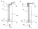
前記流動床反応器内または反応器よりも下流側にサイクロンを配置し、該サイクロンにより、触媒粒子(A)や不活性粒子(B)の一部を、捕集し、サイクロンよりも上流側の反応容器中に戻すための態様としては特に限定はないが、例えば図1(a)、(b)に示す態様が挙げられる。 A cyclone is disposed in the fluidized bed reactor or downstream of the reactor, and the catalyst particles (A) and a part of the inert particles (B) are collected by the cyclone, and upstream of the cyclone. Although there is no limitation in particular as an aspect for returning in a reaction container, For example, the aspect shown to Fig.1 (a) and (b) is mentioned.
図1(a)、(b)に示す態様では、流動床反応器の最上流側に、塩化水素および酸素(原料ガスA1)を供給するためのガス入口10bと、流動床反応器の最下流側に、生成物である塩素や未反応ガス(生成ガスA2)を排出するためのガス出口10cと、反応容器の内部に、直上(下流側)に触媒粒子(A)および反応不活性な粒子(B)14を載置する有孔板10dと、が設置されている。このような有孔板10dは、粒子とガスとの混合を促進するために設置されており、有孔板の開孔率、動床反応容器のガス入り口10bとガス出口cとの間における設置間隔、枚数などは、状況に応じて適宜調整することができる。
1 (a) and 1 (b), a
さらに、図1(a)に示す態様では、流動床反応器10の内部にサイクロン11が配置されており、図1(b)に示す態様では、反応器の外部、すなわち反応器よりも下流側にサイクロン11が配置されている。
Further, in the embodiment shown in FIG. 1 (a), a
図1(a)に示す態様では、反応器内部10aにサイクロン11が配置されており、図1(b)に示す態様では、反応器よりも下流側にサイクロン11が配置されており、該サイクロンによって、触媒粒子(A)や不活性粒子(B)の一部(反応器内部で浮遊・上昇した粒子)を捕集する。
In the embodiment shown in FIG. 1 (a), a
捕集された反応器内部で浮遊・上昇した粒子は、サイクロンの粒子出口13から、サイクロンよりも上流側の反応器内部10aに戻される。
図1(a)、(b)の態様のように、サイクロンを配置することにより、触媒粒子(A)や不活性粒子(B)の一部が、反応器内部で浮遊・上昇した場合であっても、触媒粒子(A)や不活性粒子(B)を反応器内部10aに好適に循環させることが可能である。
The particles floating and rising inside the collected reactor are returned from the
As shown in FIGS. 1 (a) and 1 (b), when the cyclone is arranged, a part of the catalyst particles (A) and the inert particles (B) float and rise inside the reactor. However, the catalyst particles (A) and the inert particles (B) can be suitably circulated in the
なお、上記サイクロンは、粒子の捕集ができれば、どのような形状、仕様のものでも使用することができる。また、反応条件に応じて、サイクロンは、適宜配置することができ、図1(a)に示されるように反応器内に配置されていてもよく、図1(b)に示されるように反応器外に配置されていてもよい。また、本反応は発熱反応であるため、熱交換器を反応器内部に配置し、除熱しやすい構造とすることも可能である。 The cyclone can be used in any shape and specification as long as particles can be collected. In addition, the cyclone can be appropriately arranged according to the reaction conditions, and may be arranged in the reactor as shown in FIG. 1 (a), or the reaction as shown in FIG. 1 (b). You may arrange | position outside the vessel. In addition, since this reaction is an exothermic reaction, it is possible to arrange a heat exchanger inside the reactor to make it easy to remove heat.
以下、本発明を実施例、比較例によって更に詳述するが、本発明はこれによって限定されるものではない。
各実施例および比較例において使用された触媒粒子(A)の調製、各粒子(触媒粒子(A)および反応不活性な粒子(B))の平均粒子径、嵩密度および終末速度の測定、ならびに各実施例および比較例の評価は、以下の条件・基準に基づいて実施された。
Hereinafter, the present invention will be described in more detail with reference to Examples and Comparative Examples, but the present invention is not limited thereto.
Preparation of catalyst particles (A) used in each example and comparative example, measurement of average particle diameter, bulk density and terminal velocity of each particle (catalyst particles (A) and reaction-inactive particles (B)), and Evaluation of each Example and the comparative example was implemented based on the following conditions and criteria.
(1)触媒粒子(A)の調製
各実施例および比較例で使用された触媒粒子1〜5は、下記条件により調製された。
(i)触媒粒子1の調製
水150gに、塩化第二銅(和光純薬、特級)2.98g、塩化サマリウム・六水和物(和光純薬、特級)3.26g、塩化カリウム(和光純薬、特級)1.54gを加え、攪拌して溶液Aを得た。
(1) Preparation of catalyst particles (A) The catalyst particles 1 to 5 used in each Example and Comparative Example were prepared under the following conditions.
(I) Preparation of catalyst particle 1 To 150 g of water, 2.98 g of cupric chloride (Wako Pure Chemical, special grade), 3.26 g of samarium chloride hexahydrate (Wako Pure Chemical, special grade), potassium chloride (Wako Pure) 1.54 g (drug, special grade) was added and stirred to obtain Solution A.
次いで、シリカゲル担体(富士シリシア化学製、Q−15、粒径75〜150μm)50gを、直径25cmのパン型ミキサ−に入れ、回転数30rpmで回転させながら、このシリカゲル担体に、溶液Aを、1流体スプレーノズルを用いスプレー状にして吹き付けながら加えて、回転を2h行い、シリカゲル担体に溶液Aを吸液させた。その後、溶液Aを吸液したシリカゲル担体をロータリーエバポレーターに移し、95℃で30min乾燥して、Cu:K:Sm:SiO2=2.5:1.5:2.5:93.5の重量比率(触媒粒子100重量%あたりの銅元素の重量:2.36重量%)の担持触媒(触媒粒子1)を得た。 Next, 50 g of a silica gel carrier (manufactured by Fuji Silysia Chemical Co., Ltd., Q-15, particle size 75 to 150 μm) is put in a pan-type mixer having a diameter of 25 cm, and while rotating at a rotation speed of 30 rpm, It was added while spraying in a spray form using a one-fluid spray nozzle, rotating for 2 hours, and the solution A was absorbed into the silica gel carrier. Thereafter, the silica gel carrier having absorbed the solution A was transferred to a rotary evaporator and dried at 95 ° C. for 30 minutes to obtain a weight of Cu: K: Sm: SiO 2 = 2.5: 1.5: 2.5: 93.5. A supported catalyst (catalyst particles 1) in a ratio (weight of copper element per 100% by weight of catalyst particles: 2.36% by weight) was obtained.
得られた触媒粒子1の平均粒子径および嵩密度を、下記「平均粒子径および嵩密度の測定」に基づいてそれぞれ測定したところ、触媒粒子1の平均粒子径は110μmであり、嵩密度は410kg/m3であった。また、得られた触媒粒子1の終末速度を、下記「終末速度の測定」に基づいて測定したところ、触媒粒子1の終末速度は0.25m/sであった。 When the average particle diameter and bulk density of the obtained catalyst particles 1 were measured based on the following “measurement of average particle diameter and bulk density”, the average particle diameter of the catalyst particles 1 was 110 μm and the bulk density was 410 kg. / M 3 . Moreover, when the terminal velocity of the obtained catalyst particle 1 was measured based on the following “measurement of terminal velocity”, the terminal velocity of the catalyst particle 1 was 0.25 m / s.
(ii)触媒粒子2の調製
担体を、シリカゲル担体(富士シリシア化学製、Q−15、粒径75〜500μm)に変更し、Cu:K:Sm:SiO2=3.5:2.1:3.5:90.9の重量比率(触媒粒子100重量%あたりの銅元素の重量:3.20重量%)の担持触媒を得たこと以外は、触媒粒子1と同様の調製条件で、担持触媒(触媒粒子2)を得た。
(Ii) Preparation of catalyst particles 2 The support was changed to a silica gel support (F-15, manufactured by Fuji Silysia Chemical Co., Ltd., particle size 75 to 500 μm), and Cu: K: Sm: SiO 2 = 3.5: 2.1: The catalyst was supported under the same preparation conditions as catalyst particle 1 except that a supported catalyst having a weight ratio of 3.5: 90.9 (weight of copper element per 100% by weight of catalyst particle: 3.20% by weight) was obtained. A catalyst (catalyst particles 2) was obtained.
また、触媒粒子1の場合と同様に、平均粒子径、嵩密度および終末速度を測定したところ、触媒粒子2の平均粒子径は220μmであり、嵩密度は450kg/m3、終末速度は1.10m/sであった。 Further, as in the case of the catalyst particle 1, the average particle diameter, the bulk density, and the terminal velocity were measured. As a result, the average particle size of the catalyst particle 2 was 220 μm, the bulk density was 450 kg / m 3 , and the terminal velocity was 1. It was 10 m / s.
(iii)触媒粒子3の調製
担体を、シリカゲル担体(富士シリシア化学製、Q−10、粒径75〜150μm)に変更し、Cu:K:Sm:SiO2=1.5:0.9:1.5:96.1の重量比率(触媒粒子100重量%あたりの銅元素の重量:1.45重量%)の担持触媒を得たこと以外は、触媒粒子1と同様の調製条件で、担持触媒(触媒粒子3)を得た。
(Iii) Preparation of catalyst particles 3 The support was changed to a silica gel support (Q-10, manufactured by Fuji Silysia Chemical Co., Ltd., particle size 75 to 150 μm), and Cu: K: Sm: SiO 2 = 1.5: 0.9: The catalyst was supported under the same preparation conditions as catalyst particle 1 except that a supported catalyst having a weight ratio of 1.5: 96.1 (weight of copper element per 100% by weight of catalyst particle: 1.45% by weight) was obtained. A catalyst (catalyst particles 3) was obtained.
また、触媒粒子1の場合と同様に、平均粒子径、嵩密度および終末速度を測定したところ、触媒粒子3の平均粒子径は96μmであり、嵩密度は450kg/m3であり、終末速度は0.21m/sであった。 Further, as in the case of the catalyst particle 1, the average particle size, the bulk density, and the terminal velocity were measured. As a result, the average particle size of the catalyst particle 3 was 96 μm, the bulk density was 450 kg / m 3 , and the terminal velocity was It was 0.21 m / s.
(iv)触媒粒子4の調製
担体を、シリカゲル担体(富士シリシア化学製、Q−15、粒径75〜300μm)に変更し、Cu:K:Sm:SiO2=5:3:5:87の重量比率(触媒粒子100重量%あたりの銅元素の重量:4.50重量%)の担持触媒を得たこと以外は、触媒粒子1と同様の調製条件で、担持触媒(触媒粒子4)を得た。
(Iv) Preparation of catalyst particles 4 The support was changed to a silica gel support (F-15 manufactured by Fuji Silysia Chemical Co., Ltd., Q-15, particle size 75 to 300 μm), and Cu: K: Sm: SiO 2 = 5: 3: 5: 87 A supported catalyst (catalyst particle 4) was obtained under the same preparation conditions as catalyst particle 1, except that a supported catalyst in a weight ratio (weight of copper element per 100% by weight of catalyst particle: 4.50% by weight) was obtained. It was.
また、触媒粒子1の場合と同様に、平均粒子径、嵩密度および終末速度を測定したところ、触媒粒子4の平均粒子径は140μmであり、嵩密度は460kg/m3であり、終末速度は0.45m/sであった。 Further, as in the case of the catalyst particle 1, the average particle diameter, the bulk density, and the terminal speed were measured. As a result, the average particle diameter of the catalyst particle 4 was 140 μm, the bulk density was 460 kg / m 3 , and the terminal speed was It was 0.45 m / s.
(v)触媒粒子5の調製
担体を、シリカゲル担体(富士シリシア化学製、Q−15、粒径75〜300μm)に変更し、Cu:K:Sm:SiO2=10:6:10:74の重量比率(触媒粒子100重量%あたりの銅元素の重量:8.09重量%)の担持触媒を得たこと以外は、触媒粒子1と同様の調製条件で、担持触媒(触媒粒子5)を得た。
(V) Preparation of catalyst particles 5 The support was changed to a silica gel support (F-15, manufactured by Fuji Silysia Chemical Co., Ltd., Q-15, particle size 75 to 300 μm), and Cu: K: Sm: SiO 2 = 10: 6: 10: 74 A supported catalyst (catalyst particle 5) was obtained under the same preparation conditions as catalyst particle 1, except that a supported catalyst in a weight ratio (weight of copper element per 100% by weight of catalyst particle: 8.09% by weight) was obtained. It was.
また、触媒粒子1の場合と同様に、平均粒子径、嵩密度および終末速度を測定したところ、触媒粒子5の平均粒子径は140μmであり、嵩密度は500kg/m3であり、終末速度は0.49m/sであった。 Further, as in the case of the catalyst particles 1, the average particle diameter, the bulk density, and the terminal velocity were measured. As a result, the average particle diameter of the catalyst particles 5 was 140 μm, the bulk density was 500 kg / m 3 , and the terminal velocity was It was 0.49 m / s.
(2)平均粒子径および嵩密度の測定
各実施例および比較例で使用される触媒粒子(A)および反応不活性な粒子(B)の、平均粒子径を、MicrotracMT3300EXII(Microtrac社製粒度分析計)を用いてレーザー光回折散乱法(測定波長21nm〜1408μm)により求めた。
(2) Measurement of average particle diameter and bulk density The average particle diameter of the catalyst particles (A) and reaction-inactive particles (B) used in each of the examples and comparative examples was measured using Microtrac MT3300EXII (a particle size analyzer manufactured by Microtrac). ) Using a laser light diffraction scattering method (measurement wavelength: 21 nm to 1408 μm).
また、各実施例および比較例で使用される触媒粒子および不活性粒子について、それぞれの嵩密度を、100mlメスシリンダーに20mlの容積に粒子を充填した際の重量より求めた。 Moreover, about the catalyst particle | grains and inert particle | grains which are used by each Example and a comparative example, each bulk density was calculated | required from the weight at the time of filling a particle | grain with a 20 ml volume to a 100 ml graduated cylinder.
(3)終末速度の測定
各実施例および比較例で使用される触媒粒子(A)および反応不活性な粒子(B)の終末速度(m/s)を、下記のストークスの式から算出した。
(3) Measurement of terminal velocity The terminal velocity (m / s) of the catalyst particles (A) and reaction-inactive particles (B) used in each Example and Comparative Example was calculated from the following Stokes equation.
なお、各粒子の嵩密度は、粒子密度の0.6倍の値とし、流動床反応器内の気体を20℃の空気であるとし、流動床反応器内における空気の密度(ρg)を1.2kg/m3、空気の粘度を0.018mPa・s、重力加速度を9.807m/s2とした。 The bulk density of each particle is 0.6 times the particle density, the gas in the fluidized bed reactor is air at 20 ° C., and the air density (ρ g ) in the fluidized bed reactor is The viscosity of air was set to 1.2 kg / m 3 , the viscosity of air was set to 0.018 mPa · s, and the acceleration of gravity was set to 9.807 m / s 2 .
![]()
また、各粒子の終末速度と、実施例および比較例におけるガス空塔速度との比も求めた。
![]()
Further, the ratio between the terminal velocity of each particle and the gas superficial velocity in the examples and comparative examples was also determined.
(4)評価方法
各実施例または比較例で使用された触媒粒子(A)および反応不活性な粒子(B)について、特に記述がない限りは、以下の条件にて、活性評価および流動性評価を行った。
(4) Evaluation method Unless otherwise specified, the activity evaluation and fluidity evaluation of the catalyst particles (A) and the reaction-inactive particles (B) used in each example or comparative example were performed under the following conditions. Went.
(i)活性評価
ヨウ化カリウム(関東化学、オキシダント測定用)を水に溶解し、0.2mol/l溶液を調整した。この溶液300mlに生成ガスを8分間吸収させた。生成ガスを吸収した溶液を、0.1mol/lチオ硫酸ナトリウム溶液(関東化学)で滴定し、該チオ硫酸ナトリウム溶液の滴定量に基づいて、各実施例または比較例にて生成した塩素のモル量を測定し、塩化水素の転化率を求めた。
(I) Activity evaluation Potassium iodide (Kanto Chemical Co., Inc. for oxidant measurement) was dissolved in water to prepare a 0.2 mol / l solution. The product gas was absorbed into 300 ml of this solution for 8 minutes. The solution in which the product gas was absorbed was titrated with a 0.1 mol / l sodium thiosulfate solution (Kanto Chemical), and based on the titration amount of the sodium thiosulfate solution, the mol of chlorine produced in each example or comparative example. The amount was measured to determine the conversion rate of hydrogen chloride.
(ii)流動性評価
反応開始から2時間経過時において、熱電対を用いてガラスフィルター直上(フィルターより下流側0cm)およびフィルターより下流側4cmの各位置の温度を測定し、その温度差を求めた。この温度差が小さいほど蓄熱が小さく、流動性良好であると判断できる。
(Ii) Evaluation of fluidity After 2 hours from the start of the reaction, the temperature at each position immediately above the glass filter (0 cm downstream from the filter) and 4 cm downstream from the filter is measured using a thermocouple, and the temperature difference is obtained. It was. It can be determined that the smaller the temperature difference, the smaller the heat storage and the better the fluidity.
[実施例1]
触媒粒子1と、不活性粒子(B1)としてシリカゲル(富士シリシア化学製、Q−6、粒径75〜150μm、平均粒子径100μm、嵩密度500kg/m3、終末速度0.25m/s)とを、触媒粒子1:Q−6=9:1の重量比となるように混合して、混合粒子1を得た。混合粒子1には、該混合粒子(触媒粒子1およびシリカゲル(Q−6))100重量%あたり、銅元素が2.12重量%含まれる。
[Example 1]
As catalyst particles 1 and inert particles (B1), silica gel (manufactured by Fuji Silysia Chemical, Q-6, particle size 75-150 μm, average particle size 100 μm, bulk density 500 kg / m 3 , terminal velocity 0.25 m / s) Were mixed at a weight ratio of catalyst particles 1: Q-6 = 9: 1 to obtain mixed particles 1. The mixed particles 1 contain 2.12% by weight of copper element per 100% by weight of the mixed particles (catalyst particles 1 and silica gel (Q-6)).
次いで、両端の一方にガス入口、他方にガス出口を備え、ガス入口から下流側130mmの位置にガラスフィルター(孔径;16〜40μm)を備えたハステロイ製反応管(内径;23mm、長さ;500mm、メッシュ直上(メッシュより下流側0cm)とメッシュより下流側4cmの位置にそれぞれ温度測定用熱電対内挿管(直径3mm)を備える。)を設置した。21.5mlの混合粒子1を、ガラスフィルター直上に、下流側から充填した。この反応管に、ガス入口から、塩化水素:酸素:窒素=50:30:20の割合(モル比)で混合された原料ガスを合計130ml/minで供給し、原料ガスの風圧により、メッシュ上の触媒粒子1および不活性粒子を流動させながら、原料ガスを空塔速度1.2cm/s、反応温度360℃、反応時間2時間の反応条件において反応させて、生成ガスを採取した。
得られた生成ガスについて、上記「(4)評価方法」に基づき、活性評価および流動性評価を行った。得られた結果を表1に示す。
Next, a Hastelloy reaction tube (inner diameter: 23 mm, length: 500 mm) provided with a gas inlet at one end and a gas outlet at the other, and a glass filter (pore diameter: 16 to 40 μm) at a position 130 mm downstream from the gas inlet. In addition, a thermocouple intubation tube (diameter 3 mm) was installed immediately above the mesh (0 cm downstream from the mesh) and 4 cm downstream from the mesh. 21.5 ml of the mixed particles 1 were filled directly on the glass filter from the downstream side. A raw material gas mixed in a ratio (molar ratio) of hydrogen chloride: oxygen: nitrogen = 50: 30: 20 is supplied from the gas inlet to this reaction tube at a total of 130 ml / min. The raw material gas was reacted under the reaction conditions of a superficial velocity of 1.2 cm / s, a reaction temperature of 360 ° C., and a reaction time of 2 hours while fluidizing the catalyst particles 1 and the inert particles.
The obtained product gas was subjected to activity evaluation and fluidity evaluation based on the “(4) Evaluation method”. The obtained results are shown in Table 1.
[実施例2]
触媒粒子1と、不活性粒子(B1)としてシリカゲル(Q−6、粒径75〜150μm、平均粒子径100μm、嵩密度500kg/m3、終末速度0.25m/s)とを、触媒粒子1:Q−6=7:3の重量比となるように混合して、混合粒子2を得た。得られた混合粒子2を反応管に充填したこと以外は、実施例1と同様に反応させて生成ガスを採取し、活性評価および流動性評価を行った。得られた結果を表1に示す。なお、混合粒子2には、該混合粒子(触媒粒子1およびQ−6)100重量%あたり、銅元素が1.65重量%含まれる。
[Example 2]
Catalyst particles 1 and silica gel (Q-6, particle size 75 to 150 μm, average particle size 100 μm, bulk density 500 kg / m 3 , terminal velocity 0.25 m / s) as inert particles (B1) are used as catalyst particles 1 : Q-6 = 7: 3 was mixed to obtain a mixed particle 2. Except that the obtained mixed particles 2 were filled in the reaction tube, the reaction was carried out in the same manner as in Example 1 to collect the generated gas, and the activity evaluation and fluidity evaluation were performed. The obtained results are shown in Table 1. The mixed particles 2 contain 1.65% by weight of copper element per 100% by weight of the mixed particles (catalyst particles 1 and Q-6).
[比較例1]
触媒粒子1のみを、反応管に充填したこと以外は、実施例1と同様に反応させて生成ガスを採取し、活性評価および流動性評価を行った。得られた結果を表1に示す。
[Comparative Example 1]
Except that only the catalyst particles 1 were filled in the reaction tube, the reaction was carried out in the same manner as in Example 1 to collect the product gas, and the activity evaluation and fluidity evaluation were performed. The obtained results are shown in Table 1.
[実施例3]
不活性粒子(B1)であるシリカゲルと、それと平均粒子径および嵩密度が異なる不活性粒子(不活性粒子(B2))を添加することによる活性および流動性への影響を確認するために、触媒粒子1と、不活性粒子(B1)としてシリカゲル(Q−6、粒径75〜150μm、平均粒子径100μm、嵩密度500kg/m3、終末速度0.25m/s)および不活性粒子(B2)として溶融シリカ(電気化学工業製、FB−40S、平均粒子径40μm、嵩密度1300kg/m3、終末速度0.10m/s)とを、触媒粒子1:Q−6:FB−40S=8:1:1の重量比になるように混合して、混合粒子3を得た。得られた混合粒子3を反応管に充填したこと以外は、実施例1と同様に反応させて生成ガスを採取し、活性評価および流動性評価を行った。得られた結果を表1に示す。なお、混合粒子3には、該混合粒子(触媒粒子1、Q−6およびFB−40S)100重量%あたり、銅元素が1.89重量%含まれる。
[Example 3]
In order to confirm the influence on the activity and fluidity by adding silica gel which is inert particles (B1) and inert particles (inactive particles (B2)) having an average particle diameter and bulk density different from that, a catalyst Particle 1 and silica gel (Q-6, particle size 75-150 μm, average particle size 100 μm, bulk density 500 kg / m 3 , terminal velocity 0.25 m / s) as inert particles (B1) and inert particles (B2) Fused silica (manufactured by Denki Kagaku Kogyo Co., Ltd., FB-40S, average particle size 40 μm, bulk density 1300 kg / m 3 , terminal velocity 0.10 m / s) and catalyst particles 1: Q-6: FB-40S = 8: The mixed particles 3 were obtained by mixing at a weight ratio of 1: 1. Except that the obtained mixed particles 3 were filled in the reaction tube, the reaction was carried out in the same manner as in Example 1 to collect the generated gas, and the activity evaluation and fluidity evaluation were performed. The obtained results are shown in Table 1. The mixed particles 3 contain 1.89% by weight of copper element per 100% by weight of the mixed particles (catalyst particles 1, Q-6 and FB-40S).
[実施例4]
触媒粒子2と、不活性粒子(B1)としてシリカゲル(Q−15、粒径75〜500μm、平均粒子径220μm、嵩密度350kg/m3、終末速度0.85m/s)とを、8:2の重量比となるように混合して、混合粒子4を得た。得られた混合粒子4を反応管に充填したこと以外は、実施例1と同様に反応させて生成ガスを採取し、活性評価および流動性評価を行った。得られた結果を表1に示す。なお、混合粒子4には、該混合粒子(触媒粒子2およびQ−15)100重量%あたり、銅元素が2.56重量%含まれる。
[Example 4]
Catalyst particles 2 and silica gel (Q-15, particle size 75-500 μm, average particle size 220 μm, bulk density 350 kg / m 3 , terminal velocity 0.85 m / s) as inert particles (B1) 8: 2 To obtain a mixed particle 4. Except that the obtained mixed particles 4 were filled in the reaction tube, the reaction was carried out in the same manner as in Example 1 to collect the generated gas, and the activity evaluation and fluidity evaluation were performed. The obtained results are shown in Table 1. The mixed particles 4 contain 2.56% by weight of copper element per 100% by weight of the mixed particles (catalyst particles 2 and Q-15).
[比較例2]
触媒粒子2のみを、反応管に充填したこと以外は、実施例1と同様に反応させて生成ガスを採取し、活性評価および流動性評価を行った。得られた結果を表1に示す。
[Comparative Example 2]
Except that only the catalyst particles 2 were filled in the reaction tube, the reaction was carried out in the same manner as in Example 1 to collect the generated gas, and the activity evaluation and fluidity evaluation were performed. The obtained results are shown in Table 1.
[実施例5]
触媒粒子3と、不活性粒子(B1)としてシリカゲル(Q−6、粒径75〜150μm、平均粒子径100μm、嵩密度500kg/m3、終末速度0.25m/s)とを、8:2の重量比となるように混合して、混合粒子5を得た。得られた混合粒子5を反応管に充填したこと以外は、実施例1と同様に反応させて生成ガスを採取し、活性評価および流動性評価を行った。得られた結果を表1に示す。なお、混合粒子5には、該混合粒子(触媒粒子3およびQ−6)100重量%あたり、銅元素が1.16重量%含まれる。
[Example 5]
Catalyst particles 3 and silica gel (Q-6, particle size 75 to 150 μm, average particle size 100 μm, bulk density 500 kg / m 3 , terminal velocity 0.25 m / s) as inert particles (B1) 8: 2 To obtain a mixed particle 5. Except that the obtained mixed particles 5 were filled in the reaction tube, the reaction was carried out in the same manner as in Example 1 to collect the generated gas, and the activity evaluation and fluidity evaluation were performed. The obtained results are shown in Table 1. The mixed particles 5 contain 1.16% by weight of copper element per 100% by weight of the mixed particles (catalyst particles 3 and Q-6).
[比較例3]
触媒粒子3のみを、反応管に充填したこと以外は、実施例1と同様に反応させて生成ガスを採取し、活性評価および流動性評価を行った。得られた結果を表1に示す。
[Comparative Example 3]
Except that only the catalyst particles 3 were filled in the reaction tube, the reaction was carried out in the same manner as in Example 1 to collect the product gas, and the activity evaluation and fluidity evaluation were performed. The obtained results are shown in Table 1.
[実施例6]
触媒粒子4と、不活性粒子(B1)としてシリカゲル(Q−15、粒径75〜300μm、平均粒子径140μm、嵩密度360kg/m3、終末速度0.36m/s)とを、2:8の重量比となるように混合して、混合粒子6を得た。得られた混合粒子6を反応管に充填したこと以外は、実施例1と同様に反応させて生成ガスを採取し、活性評価および流動性評価を行った。得られた結果を表1に示す。なお、混合粒子6には、該混合粒子(触媒粒子4およびQ−15)100重量%あたり、銅元素が0.90重量%含まれる。
[Example 6]
Catalyst particles 4 and silica gel (Q-15, particle size 75 to 300 μm, average particle size 140 μm, bulk density 360 kg / m 3 , terminal velocity 0.36 m / s) as inert particles (B1) are 2: 8. To obtain a mixed particle 6. Except that the obtained mixed particles 6 were filled in the reaction tube, the reaction was carried out in the same manner as in Example 1 to collect the generated gas, and the activity evaluation and fluidity evaluation were performed. The obtained results are shown in Table 1. The mixed particles 6 contain 0.90% by weight of copper element per 100% by weight of the mixed particles (catalyst particles 4 and Q-15).
[実施例7]
触媒粒子5と、不活性粒子(B1)としてシリカゲル(Q−15、粒径75〜300μm、平均粒子径140μm、嵩密度360kg/m3、終末速度0.36m/s)とを、3.5:6.5の重量比となるように混合して、混合粒子7を得た。得られた混合粒子7を反応管に充填したこと以外は、実施例1と同様に反応させて生成ガスを採取し、活性評価および流動性評価を行った。得られた結果を表1に示す。なお、混合粒子7には、該混合粒子(触媒粒子5およびQ−15)100重量%あたり、銅元素が2.83重量%含まれる。
[Example 7]
Catalyst particles 5 and silica gel (Q-15, particle size 75 to 300 μm, average particle size 140 μm, bulk density 360 kg / m 3 , terminal velocity 0.36 m / s) as inert particles (B1) 3.5 : The mixed particles 7 were obtained by mixing so that the weight ratio was 6.5. Except that the obtained mixed particles 7 were filled in the reaction tube, the reaction was carried out in the same manner as in Example 1 to collect the generated gas, and the activity evaluation and fluidity evaluation were performed. The obtained results are shown in Table 1. The mixed particles 7 contain 2.83% by weight of copper element per 100% by weight of the mixed particles (catalyst particles 5 and Q-15).
[実施例8]
触媒粒子3と、不活性粒子(B1)としてシリカゲル(Q−6、粒径75〜150μm、平均粒子径100μm、嵩密度500kg/m3、終末速度0.25m/s)とを、4:6の重量比となるように混合して、混合粒子8を得た。得られた混合粒子8を反応管に充填したこと以外は、実施例1と同様に反応させて生成ガスを採取し、活性評価および流動性評価を行った。得られた結果を表1に示す。なお、混合粒子8には、該混合粒子(触媒粒子3およびQ−6)100重量%あたり、銅元素が0.58重量%含まれる。
[Example 8]
Catalyst particles 3 and silica gel (Q-6, particle size 75 to 150 μm, average particle size 100 μm, bulk density 500 kg / m 3 , terminal velocity 0.25 m / s) as inert particles (B1) 4: 6 The mixed particles 8 were obtained by mixing so that the weight ratio was. Except that the obtained mixed particles 8 were filled in the reaction tube, the reaction was carried out in the same manner as in Example 1 to collect the generated gas, and the activity evaluation and fluidity evaluation were performed. The obtained results are shown in Table 1. The mixed particles 8 contain 0.58% by weight of copper element per 100% by weight of the mixed particles (catalyst particles 3 and Q-6).
[比較例4]
触媒粒子4と、不活性粒子(B1)としてシリカゲル(Q−15、粒径75〜300μm、平均粒子径140μm、嵩密度360kg/m3、終末速度0.36m/s)とを、0.4:9.6の重量比となるように混合して、混合粒子9を得た。得られた混合粒子9を反応管に充填したこと以外は、実施例1と同様に反応させて生成ガスを採取し、活性評価および流動性評価を行った。得られた結果を表1に示す。なお、混合粒子9には、該混合粒子(触媒粒子4およびQ−15)100重量%あたり、銅元素が0.18重量%含まれる。
[Comparative Example 4]
Catalyst particles 4 and silica gel (Q-15, particle size 75 to 300 μm, average particle size 140 μm, bulk density 360 kg / m 3 , terminal velocity 0.36 m / s) as inert particles (B1) 0.4 : The mixed particles 9 were obtained by mixing so that the weight ratio was 9.6. Except that the obtained mixed particles 9 were filled in the reaction tube, the reaction was carried out in the same manner as in Example 1 to collect the generated gas, and the activity evaluation and fluidity evaluation were performed. The obtained results are shown in Table 1. The mixed particles 9 contain 0.18% by weight of copper element per 100% by weight of the mixed particles (catalyst particles 4 and Q-15).
[比較例5]
触媒粒子5と、不活性粒子(B1)としてシリカゲル(Q−15、粒径75〜300μm、平均粒子径140μm、嵩密度360kg/m3、終末速度0.36m/s)とを、6:4の重量比となるように混合して、混合粒子10を得た。得られた混合粒子10を反応管に充填したこと以外は、実施例1と同様に反応させて生成ガスを採取し、活性評価および流動性評価を行った。得られた結果を表1に示す。なお、混合粒子10には、該混合粒子(触媒粒子5およびQ−15)100重量%あたり、銅元素が4.85重量%含まれる。
[Comparative Example 5]
Catalyst particles 5 and silica gel (Q-15, particle size 75 to 300 μm, average particle size 140 μm, bulk density 360 kg / m 3 , terminal velocity 0.36 m / s) as inert particles (B1) 6: 4 To obtain a
[比較例6]
終末速度とガス空塔速度との比が小さい場合の影響を確認するために、触媒粒子2と、不活性粒子(B1)としてシリカゲル(Q−15、粒径75〜500μm、平均粒子径220μm、嵩密度350kg/m3、終末速度0.85m/s)とを、8:2の重量比となるように混合して、混合粒子11を得た。得られた混合粒子11を反応管に充填したことと、原料ガスの反応条件において、空塔速度を1.2cm/sから0.7cm/sに変更したこと以外は、実施例1と同様に反応させて生成ガスを採取し、活性評価および流動性評価を行った。得られた結果を表1に示す。なお、混合粒子11には、該混合粒子(触媒粒子2およびQ−15)100重量%あたり、銅元素が2.56重量%含まれる。
[Comparative Example 6]
In order to confirm the influence when the ratio between the terminal velocity and the gas superficial velocity is small, the catalyst particles 2 and the inert particles (B1) as silica gel (Q-15, particle size 75-500 μm, average particle size 220 μm, A bulk density of 350 kg / m 3 and an end speed of 0.85 m / s) were mixed so as to obtain a weight ratio of 8: 2 to obtain
10:流動床反応器
10a:反応器内部
10b:ガス入口
10c:ガス出口
10d:有孔板
11:サイクロン
12:粒子循環用配管
13:粒子出口
14:触媒粒子(A)および反応不活性粒子(B)
A1:原料ガス
A2:生成ガス
10:
A1: Raw material gas A2: Product gas
Claims (9)
前記流動床反応器内に、下記要件(A1)および(A2)を満たす触媒粒子(A)と、下記要件(B1)を満たす反応不活性な粒子(B)とが存在し、
前記触媒粒子(A)および前記反応不活性な粒子(B)との合計100重量%あたり、銅元素の含有量が0.3〜4.5重量%であることを特徴とする塩化水素から塩素を製造する方法。
(A1)触媒粒子(A)のストークスの式から算出される20℃における空気中での終末速度が、前記流動床反応器内でのガス空塔速度の1.1〜100倍である。
(A2)触媒粒子(A)が、触媒粒子(A)100重量%あたり、銅元素を0.5〜12重量%含む。
(B1)反応不活性な粒子(B)のストークスの式から算出される20℃における空気中での終末速度が、前記流動床反応器内でのガス空塔速度の1.1〜100倍である。 A method for producing chlorine from hydrogen chloride by oxidizing hydrogen chloride in a fluidized bed reactor,
In the fluidized bed reactor, there are catalyst particles (A) that satisfy the following requirements (A1) and (A2), and reaction-inactive particles (B) that satisfy the following requirements (B1):
Hydrogen chloride to chlorine, wherein the content of copper element is 0.3 to 4.5% by weight per 100% by weight in total of the catalyst particles (A) and the reaction-inactive particles (B) How to manufacture.
(A1) The terminal velocity in air at 20 ° C. calculated from the Stokes equation of the catalyst particles (A) is 1.1 to 100 times the gas superficial velocity in the fluidized bed reactor.
(A2) The catalyst particles (A) contain 0.5 to 12% by weight of copper element per 100% by weight of the catalyst particles (A).
(B1) The terminal velocity in air at 20 ° C. calculated from the Stokes equation of the reaction-inactive particles (B) is 1.1 to 100 times the gas superficial velocity in the fluidized bed reactor. is there.
前記流動床反応器内に含まれる触媒粒子(A)と反応不活性な粒子(B)との重量比((A)/(B))が、50/50〜99/1の範囲にある、請求項1〜3のいずれか一項に記載の塩化水素から塩素を製造する方法。 The catalyst particles (A) contain 0.5 to 4.5% by weight of copper element per 100% by weight of the catalyst particles (A),
The weight ratio ((A) / (B)) of catalyst particles (A) and reaction-inactive particles (B) contained in the fluidized bed reactor is in the range of 50/50 to 99/1. The method to manufacture chlorine from the hydrogen chloride as described in any one of Claims 1-3.
銅元素と希土類元素との重量比が、1:0.2〜1:6.0の範囲にあり、
銅元素とアルカリ金属元素との重量比が、1:0.1〜1:4.0の範囲にある、請求項1〜5のいずれか一項に記載の塩化水素から塩素を製造する方法。 The catalyst particles (A) contain a copper element, a rare earth element and an alkali metal element,
The weight ratio of copper element to rare earth element is in the range of 1: 0.2 to 1: 6.0;
The method for producing chlorine from hydrogen chloride according to any one of claims 1 to 5, wherein the weight ratio of the copper element and the alkali metal element is in the range of 1: 0.1 to 1: 4.0.
銅元素と希土類元素との重量比が、1:0.2〜1:3.0の範囲にあり、
銅元素とアルカリ金属元素との重量比が、1:0.1〜1:2.5の範囲にある、請求項1〜5のいずれか一項に記載の塩化水素から塩素を製造する方法。 The catalyst particles (A) contain a copper element, a rare earth element and an alkali metal element,
The weight ratio of copper element to rare earth element is in the range of 1: 0.2 to 1: 3.0;
The method for producing chlorine from hydrogen chloride according to any one of claims 1 to 5, wherein the weight ratio of the copper element and the alkali metal element is in the range of 1: 0.1 to 1: 2.5.
Priority Applications (1)
| Application Number | Priority Date | Filing Date | Title |
|---|---|---|---|
| JP2010070380A JP5555026B2 (en) | 2009-03-26 | 2010-03-25 | Method for producing chlorine from hydrogen chloride using a fluidized bed reactor |
Applications Claiming Priority (3)
| Application Number | Priority Date | Filing Date | Title |
|---|---|---|---|
| JP2009076926 | 2009-03-26 | ||
| JP2009076926 | 2009-03-26 | ||
| JP2010070380A JP5555026B2 (en) | 2009-03-26 | 2010-03-25 | Method for producing chlorine from hydrogen chloride using a fluidized bed reactor |
Publications (3)
| Publication Number | Publication Date |
|---|---|
| JP2010248062A JP2010248062A (en) | 2010-11-04 |
| JP2010248062A5 JP2010248062A5 (en) | 2013-01-17 |
| JP5555026B2 true JP5555026B2 (en) | 2014-07-23 |
Family
ID=43310877
Family Applications (1)
| Application Number | Title | Priority Date | Filing Date |
|---|---|---|---|
| JP2010070380A Active JP5555026B2 (en) | 2009-03-26 | 2010-03-25 | Method for producing chlorine from hydrogen chloride using a fluidized bed reactor |
Country Status (1)
| Country | Link |
|---|---|
| JP (1) | JP5555026B2 (en) |
Families Citing this family (3)
| Publication number | Priority date | Publication date | Assignee | Title |
|---|---|---|---|---|
| JP2014125418A (en) * | 2012-12-27 | 2014-07-07 | Mitsubishi Materials Corp | Apparatus and method for producing carbon nanofiber |
| JP6486015B2 (en) * | 2014-04-25 | 2019-03-20 | 三菱ケミカル株式会社 | Fluidized bed reactor |
| JP2023533143A (en) | 2020-05-29 | 2023-08-02 | ベーアーエスエフ・エスエー | Catalyst for the oxidation of hydrogen chloride and its production |
Family Cites Families (3)
| Publication number | Priority date | Publication date | Assignee | Title |
|---|---|---|---|---|
| JPH01257102A (en) * | 1988-04-06 | 1989-10-13 | Mitsui Toatsu Chem Inc | Production of chlorine from hydrogen chloride |
| JP3852983B2 (en) * | 1996-06-21 | 2006-12-06 | 三井化学株式会社 | Catalyst for producing chlorine from hydrogen chloride |
| JP5289131B2 (en) * | 2009-03-26 | 2013-09-11 | 三井化学株式会社 | Fluidized bed catalyst for chlorine production and method for producing chlorine using the catalyst |
-
2010
- 2010-03-25 JP JP2010070380A patent/JP5555026B2/en active Active
Also Published As
| Publication number | Publication date |
|---|---|
| JP2010248062A (en) | 2010-11-04 |
Similar Documents
| Publication | Publication Date | Title |
|---|---|---|
| JP5414527B2 (en) | Catalyst, process for producing the same, and process for producing chlorine using the catalyst | |
| JP5628930B2 (en) | Catalyst for producing unsaturated aldehyde and / or unsaturated carboxylic acid, and method for producing unsaturated aldehyde and / or unsaturated carboxylic acid using the catalyst | |
| KR101795095B1 (en) | Shell catalytic converter made of a hollow cylindrical carrier body and a catalytically active oxide mass applied to the outer surface of the carrier body | |
| TW201512163A (en) | Method of producing unsaturated aldehyde and/or unsaturated carboxylic acid | |
| US8785675B2 (en) | Mixed catalyst | |
| JP6308844B2 (en) | Catalyst for producing hydrogen and method for producing hydrogen using the catalyst | |
| CN110709163A (en) | Catalyst and process for preparing same | |
| JP5468065B2 (en) | Catalyst for producing chlorine and method for producing chlorine using the catalyst | |
| JP5555026B2 (en) | Method for producing chlorine from hydrogen chloride using a fluidized bed reactor | |
| TWI501810B (en) | Production method of unsaturated nitrile | |
| JP5586382B2 (en) | Method for producing catalyst for producing unsaturated aldehyde and / or unsaturated carboxylic acid, catalyst therefor, and method for producing acrolein and / or acrylic acid using the catalyst | |
| CN109952270B (en) | Method for producing chlorine by hydrogen chloride oxidation | |
| JP5015057B2 (en) | Catalyst for synthesis of chlorine and method for producing the same, and method for synthesizing chlorine using the catalyst | |
| JP2007111581A (en) | Solid catalyst for synthesizing methacrylic acid, its preparing method and manufacturing method of methacrylic acid | |
| JP5414300B2 (en) | Chlorine production method | |
| JP2010228952A (en) | Method for producing chlorine form hydrogen chloride using fluidizing bed reactor | |
| JP5289132B2 (en) | Catalyst for producing chlorine and method for producing chlorine using the catalyst | |
| JP5503732B2 (en) | Chlorine production method | |
| JP4253176B2 (en) | Catalyst for producing acrylic acid and method for producing acrylic acid | |
| JP5289131B2 (en) | Fluidized bed catalyst for chlorine production and method for producing chlorine using the catalyst | |
| JP2012062235A (en) | Method for producing chlorine | |
| JP2017225955A (en) | MANUFACTURING METHOD OF MgO CARRYING CATALYST | |
| JP6308834B2 (en) | Catalyst for producing hydrogen and method for producing hydrogen using the catalyst |
Legal Events
| Date | Code | Title | Description |
|---|---|---|---|
| A521 | Request for written amendment filed |
Free format text: JAPANESE INTERMEDIATE CODE: A523 Effective date: 20121128 |
|
| A621 | Written request for application examination |
Free format text: JAPANESE INTERMEDIATE CODE: A621 Effective date: 20121128 |
|
| TRDD | Decision of grant or rejection written | ||
| A01 | Written decision to grant a patent or to grant a registration (utility model) |
Free format text: JAPANESE INTERMEDIATE CODE: A01 Effective date: 20140520 |
|
| A61 | First payment of annual fees (during grant procedure) |
Free format text: JAPANESE INTERMEDIATE CODE: A61 Effective date: 20140530 |
|
| R150 | Certificate of patent or registration of utility model |
Ref document number: 5555026 Country of ref document: JP Free format text: JAPANESE INTERMEDIATE CODE: R150 |
|
| R250 | Receipt of annual fees |
Free format text: JAPANESE INTERMEDIATE CODE: R250 |
|
| R250 | Receipt of annual fees |
Free format text: JAPANESE INTERMEDIATE CODE: R250 |
|
| R250 | Receipt of annual fees |
Free format text: JAPANESE INTERMEDIATE CODE: R250 |
|
| R250 | Receipt of annual fees |
Free format text: JAPANESE INTERMEDIATE CODE: R250 |
|
| R250 | Receipt of annual fees |
Free format text: JAPANESE INTERMEDIATE CODE: R250 |
|
| R250 | Receipt of annual fees |
Free format text: JAPANESE INTERMEDIATE CODE: R250 |
|
| R250 | Receipt of annual fees |
Free format text: JAPANESE INTERMEDIATE CODE: R250 |