JP5554722B2 - Clamp member, clamp and anastomosis device - Google Patents
Clamp member, clamp and anastomosis device Download PDFInfo
- Publication number
- JP5554722B2 JP5554722B2 JP2010543928A JP2010543928A JP5554722B2 JP 5554722 B2 JP5554722 B2 JP 5554722B2 JP 2010543928 A JP2010543928 A JP 2010543928A JP 2010543928 A JP2010543928 A JP 2010543928A JP 5554722 B2 JP5554722 B2 JP 5554722B2
- Authority
- JP
- Japan
- Prior art keywords
- valgus
- clamp
- organ
- gripping
- piercing
- Prior art date
- Legal status (The legal status is an assumption and is not a legal conclusion. Google has not performed a legal analysis and makes no representation as to the accuracy of the status listed.)
- Expired - Fee Related
Links
Images


Classifications
-
- A—HUMAN NECESSITIES
- A61—MEDICAL OR VETERINARY SCIENCE; HYGIENE
- A61B—DIAGNOSIS; SURGERY; IDENTIFICATION
- A61B17/00—Surgical instruments, devices or methods, e.g. tourniquets
- A61B17/11—Surgical instruments, devices or methods, e.g. tourniquets for performing anastomosis; Buttons for anastomosis
- A61B17/115—Staplers for performing anastomosis in a single operation
- A61B17/1152—Staplers for performing anastomosis in a single operation applying the staples on the outside of the lumen
-
- A—HUMAN NECESSITIES
- A61—MEDICAL OR VETERINARY SCIENCE; HYGIENE
- A61B—DIAGNOSIS; SURGERY; IDENTIFICATION
- A61B17/00—Surgical instruments, devices or methods, e.g. tourniquets
- A61B17/068—Surgical staplers, e.g. containing multiple staples or clamps
- A61B17/072—Surgical staplers, e.g. containing multiple staples or clamps for applying a row of staples in a single action, e.g. the staples being applied simultaneously
- A61B17/07207—Surgical staplers, e.g. containing multiple staples or clamps for applying a row of staples in a single action, e.g. the staples being applied simultaneously the staples being applied sequentially
-
- A—HUMAN NECESSITIES
- A61—MEDICAL OR VETERINARY SCIENCE; HYGIENE
- A61B—DIAGNOSIS; SURGERY; IDENTIFICATION
- A61B17/00—Surgical instruments, devices or methods, e.g. tourniquets
- A61B17/068—Surgical staplers, e.g. containing multiple staples or clamps
- A61B17/072—Surgical staplers, e.g. containing multiple staples or clamps for applying a row of staples in a single action, e.g. the staples being applied simultaneously
- A61B2017/07214—Stapler heads
-
- A—HUMAN NECESSITIES
- A61—MEDICAL OR VETERINARY SCIENCE; HYGIENE
- A61B—DIAGNOSIS; SURGERY; IDENTIFICATION
- A61B17/00—Surgical instruments, devices or methods, e.g. tourniquets
- A61B17/11—Surgical instruments, devices or methods, e.g. tourniquets for performing anastomosis; Buttons for anastomosis
- A61B2017/1121—Surgical instruments, devices or methods, e.g. tourniquets for performing anastomosis; Buttons for anastomosis adapted for performing tissue or graft eversion
Description
この発明は、外科手術において消化管等を縫合又は吻合するために器官組織を把持するためのクランプ部材、クランプ及び吻合器に関する。
本願は、2008年12月25日に、日本に出願された特願2008−329866号、及び特願2008―329867号に基づき優先権を主張し、その内容をここに援用する。The present invention relates to a clamp member, a clamp, and an anastomosis device for grasping an organ tissue for suturing or anastomosing a digestive tract or the like in a surgical operation.
This application claims priority based on Japanese Patent Application Nos. 2008-329866 and 2008-329867 filed in Japan on December 25, 2008, the contents of which are incorporated herein by reference.
周知のように、腸管や胃をはじめとする消化器外科分野の管腔状生体組織(器官組織等)に病変組織がある場合、その病変部位を切除した後に、正常な管腔状の生体組織同士の端部と端部(端々吻合)や端部と側部(端側吻合)、或いは側部と側部(側々吻合)を縫合又は吻合し、連続する消化管として再建する再建術が必要となる。 As is well known, when there is a diseased tissue in a luminal living tissue (organ tissue, etc.) in the field of digestive surgery including the intestinal tract and stomach, a normal luminal living tissue after excision of the lesion site. Reconstruction that reconstructs as a continuous digestive tract by suturing or anastomosing end-to-end (end-to-end anastomosis), end-to-side (end-side anastomosis), or side-to-side (end-to-side anastomosis) Necessary.
かかる筒状の生体組織の再建術において、例えば、吻合に関しては、筒状の生体組織の断端部近傍を内側に反らせて管内で縫合する内反吻合と、断端部近傍を外側に反らせて管外で縫合する外反吻合とが知られ、従来、衛生面、癒着防止等の観点から内反吻合が一般的に行なわれ、消化管の内反吻合では縫合部材であるステープルが環状に配列された環状自動吻合器が第一選択になっている(例えば特許文献1参照。)。 In the reconstruction of the cylindrical living tissue, for example, with regard to anastomosis, the inner anastomosis in which the vicinity of the stump portion of the cylindrical living tissue is bent inward and sutured in the tube, and the vicinity of the stump portion is bent outward. The valgus anastomosis that is sutured outside the tube is known. Conventionally, the varus anastomosis is generally performed from the viewpoints of hygiene and prevention of adhesion, and in the varus anastomosis of the digestive tract, staples that are suture members are arranged in a ring shape The annular automatic anastomosis device is the first choice (see, for example, Patent Document 1).
しかしながら、特許文献1に記載の自動吻合器を使用する場合、消化管の内腔に自動吻合器の本体部分を挿入したり、吻合される反対側の消化管にアンビルヘッドを挿入する必要があるために、不潔域への本体挿入や、消化管の断端が開放状態となるため、術野が汚染される可能性がある。また、操作手順が煩雑で多くの時間がかかるために手術時間が伸びる可能性があるうえ、環状自動吻合器を使用した場合の合併症の1つとしてよく知られる術後狭窄が起きる可能性があるという問題がある。
However, when using the automatic anastomosis device described in
一方、上記環状自動吻合器を用いた場合における汚染の解消や、術後狭窄の解消のために外反吻合に対する要求があり、外反吻合を短時間で効率よく行なうための手段として吻合装置が開示されている(例えば、特許文献2参照。)。 On the other hand, there is a demand for valgus anastomosis in order to eliminate contamination in the case of using the annular automatic anastomosis device and to eliminate postoperative stenosis, and an anastomosis device is a means for efficiently performing valgus anastomosis in a short time. (For example, refer to Patent Document 2).
しかしながら、特許文献2に記載の吻合装置を用いる場合には、
1)突刺歯及びすくい歯からなる把持歯がハウジングから露出しているために、把持歯に物体が接触すると把持歯が破損し又は操作者と接触すると操作者が傷つく可能性がある。
2)また、各種操作をおこなうためのレバーを有しているものの、その履行手順は複雑で、操作者は各種操作に相応の習熟を要する。
3)吻合における操作手順を誤った場合、生体組織に損傷を与える可能性がある。
という側面があった。
そこで、生体組織を容易かつ安定して把持することができ、縫合又は吻合を容易かつ効率的に行なえて、誤った操作をすることが抑制可能とされる、縫合器、吻合器をはじめとする手術用機器に対する技術が要請されている。However, when using the anastomosis device described in
1) Since the gripping teeth including the piercing teeth and the rake teeth are exposed from the housing, the gripping teeth may be damaged when an object comes in contact with the gripping teeth, or the operator may be injured when contacting the operator.
2) Moreover, although it has a lever for performing various operations, the implementation procedure is complicated, and the operator needs appropriate proficiency for various operations.
3) If the operation procedure in the anastomosis is wrong, there is a possibility that the living tissue is damaged.
There was an aspect that.
Therefore, it is possible to grasp a living tissue easily and stably, easily and efficiently perform suturing or anastomosis, and suppress an erroneous operation. There is a demand for technology for surgical devices.
本発明は、このような事情を考慮してなされたものであり、以下に記載する課題のうち少なくとも一つを解決することを目的とする。
1)突刺歯、すくい歯の損傷及び突刺歯、すくい歯により操作者が負傷することが抑制可能とされ、容易かつ効率的に生体組織を把持可能なクランプ部材を提供すること。
2)生体組織の把持及び外反を容易かつ安定して行なうことができるクランプを提供すること。
3)操作が容易で効率的な吻合を行なうことが可能な吻合器を提供すること。
4)吻合時の誤操作に起因して生体組織を損傷することを抑制可能な吻合器を提供すること。The present invention has been made in view of such circumstances, and an object thereof is to solve at least one of the problems described below.
1) To provide a clamp member that can suppress an operator from being injured by piercing teeth, rake teeth, and piercing teeth, rake teeth, and can easily and efficiently grasp a living tissue.
2) To provide a clamp capable of easily and stably gripping and valving a living tissue.
3) To provide an anastomosis device that can be operated easily and efficiently.
4) To provide an anastomosis device capable of suppressing damage to living tissue due to an erroneous operation during anastomosis.
上記課題を解決するために、この発明は以下の手段を提案している。
本発明に係る第1の発明は、クランプ部材であって、器官組織を挟むクランプ面と、器官壁を縫合する側の縫合面とを有し、縫合方向に延在して形成されたフォークに、前記フォークの長手方向に複数の突刺歯が等ピッチで配列された第1の把持歯板部材と、前記第1の把持歯板部材に沿って配置されるとともに各突刺歯と対応し前記対応する突刺歯と等ピッチに配置されかつ先端側を前記対応する突刺歯側に向けて形成される複数のすくい歯を有し、前記第1の把持歯板部材と相対移動することにより前記すくい歯の先端部が前記突刺歯の先端部と合致するように構成された第2の把持歯板部材と、前記第1の把持歯板部材と第2の把持歯板部材とを互いに相対移動可能に収納するハウジングと、前記第1の把持歯板部材と前記第2の把持歯板部材の少なくともいずれか一方に接続され、前記第1の把持歯板部材と前記第2の把持歯板部材とを長手方向に1ピッチ分相対移動させる把持歯駆動部とを有し、前記器官組織の縫合部近傍を把持するように構成された器官把持機構と、前記器官把持機構と接続され、前記器官把持機構を、前記フォークの長手方向を横切って、前記突刺歯が前記器官組織の縫合部近傍を突刺す外反前位置から前記器官組織の縫合部が縫合面に位置する外反後位置に至る外反移動範囲を移動させるように構成された外反機構と、前記フォークに配置され、前記器官把持機構の外反移動範囲を規定するとともに、前記器官把持機構を前記外反前位置と前記外反後位置のそれぞれにおいて保持し、前記器官把持機構が前記外反後位置側に移動した場合における前記第1の把持歯板部材と第2の把持歯板部材とを管理するための把持管理手段を備えることを特徴とする。In order to solve the above problems, the present invention proposes the following means.
1st invention which concerns on this invention is a clamp member, Comprising: It has the clamp surface which pinches | interposes an organ tissue, and the suture surface of the side which sutures an organ wall, and the fork formed in the suture direction was formed. A first holding tooth plate member in which a plurality of piercing teeth are arranged at an equal pitch in the longitudinal direction of the fork, and the first holding tooth plate member is disposed along the first holding tooth plate member and corresponds to each piercing tooth. The rake teeth have a plurality of rake teeth that are arranged at an equal pitch to the piercing teeth that are formed with the tip side facing the corresponding piercing tooth side, and move relative to the first grasping tooth plate member. A second gripping tooth plate member configured so that a tip end portion thereof matches a tip portion of the piercing tooth, and the first gripping tooth plate member and the second gripping tooth plate member can be moved relative to each other. A housing for housing, the first gripping tooth plate member, and the second grip A gripping tooth drive unit that is connected to at least one of the plate members and relatively moves the first gripping toothplate member and the second gripping toothplate member by one pitch in the longitudinal direction; An organ gripping mechanism configured to grip the vicinity of a sutured portion of tissue, and connected to the organ gripping mechanism, crossing the organ gripping mechanism across the longitudinal direction of the fork, and the piercing teeth are sutured to the organ tissue A valgus mechanism configured to move a valgus movement range from a position before valgus that pierces the vicinity of the part to a position after valgus where the sutured portion of the organ tissue is located on the stitching surface; and a valgus mechanism disposed on the fork. Defining the valgus movement range of the organ gripping mechanism, holding the organ gripping mechanism at each of the pre-valgus position and the post-valgus position, and moving the organ gripping mechanism toward the valgus position In case Characterized in that it comprises a gripping management means for managing serial first gripping teeth plate member and the second gripping teeth plate member.
この発明に係るクランプ部材によれば、器官把持機構の第1の把持歯板部材と第2の把持歯板部材とが相対移動することにより、突刺歯が器官組織外側の縫合部近傍を突き刺すとともに、この突刺歯の先端部にすくい歯の先端部が合致して器官組織を把持し、外反機構が、器官把持機構をクランプ部材の長手方向を横切って移動させることにより、器官組織を外反して器官壁が形成される。この明細書において、突刺歯の先端部にすくい歯の先端部が合致するとは、器官組織を把持する目的において、これらの先端部が略一致することをいう。
また、把持管理手段を備えていて、器官把持機構を外反前位置と外反後位置のそれぞれにおいて保持し、器官把持機構が外反後位置側に移動した場合に、第1の把持歯板部材と第2の把持歯板部材とが、意図しない動作をしないように適切に管理されているので、器官組織が、外反時に、突刺歯及びすくい歯から外れることが抑制され、把持した器官組織を安定して保持することができる。According to the clamp member of the present invention, the first grasping toothplate member and the second grasping toothplate member of the organ grasping mechanism move relative to each other, so that the piercing teeth pierce the vicinity of the suture part outside the organ tissue. The tip of the rake teeth matches the tip of the piercing tooth to grip the organ tissue, and the valgus mechanism moves the organ gripping mechanism across the longitudinal direction of the clamp member, thereby inverting the organ tissue. As a result, an organ wall is formed. In this specification, that the tip portion of the rake tooth matches the tip portion of the piercing tooth means that these tip portions substantially match for the purpose of grasping the organ tissue.
Also, a grip management means is provided, and the first gripping tooth plate is held when the organ gripping mechanism is held at each of the pre-valgus position and the post-valgus position, and the organ gripping mechanism is moved to the post-valgus position side. Since the member and the second grasping tooth plate member are appropriately managed so as not to perform an unintended operation, the organ tissue is prevented from being detached from the piercing teeth and the rake teeth at the time of eversion, and the grasped organ The tissue can be held stably.
本発明に係る第2の発明は、上記第1の発明に係るクランプ部材であって、前記器官把持機構は、第1の把持歯板部材と第2の把持歯板部材とが相対移動して前記器官組織を把持する場合に、前記突刺歯が突刺し方向に前進するように構成されており、前記突刺歯が前記突刺し方向の後退位置にある場合に、前記突刺歯及び前記すくい歯の先端部を格納して、前記突刺歯及び前記すくい歯の先端部が外部と接触するのを抑制する把持歯保護壁部を備えることを特徴とする。 2nd invention which concerns on this invention is a clamp member which concerns on the said 1st invention, Comprising: As for the said organ holding | grip mechanism, a 1st holding toothplate member and a 2nd holding toothplate member move relatively. When grasping the organ tissue, the piercing teeth are configured to advance in the piercing direction, and when the piercing teeth are in the retracted position in the piercing direction, the piercing teeth and the rake teeth A gripping tooth protection wall portion is provided that stores the tip portion and prevents the tip portion of the piercing tooth and the rake tooth from coming into contact with the outside.
この発明に係るクランプ部材によれば、突刺歯及びすくい歯が突刺し方向の後退位置にある場合に、把持歯保護壁部が突刺歯及びすくい歯の先端部を格納しているので、突刺歯及びすくい歯の先端部が外部の物体と接触して破損するのが抑制され、ひいては破損した突刺歯、すくい歯により器官組織を損傷することが抑制される。この明細書において突刺し方向とは、突刺し歯が器官組織外側を押える方向(突刺し歯が移動する方向)を意味する。
また、突刺歯、すくい歯が医療従事者等の操作者と接触することが抑制されるので、操作者が器官把持機構を容易、安全かつ効率的に取り扱うことができる。According to the clamp member of the present invention, when the piercing teeth and the rake teeth are in the retracted position in the piercing direction, the gripping tooth protection wall portion stores the tip portions of the piercing teeth and the rake teeth. In addition, the tip portion of the rake teeth is prevented from being damaged due to contact with an external object, and as a result, damage to the organ tissue due to the damaged piercing teeth and rake teeth is suppressed. In this specification, the piercing direction means a direction in which the piercing tooth presses the outside of the organ tissue (direction in which the piercing tooth moves).
In addition, since the stab teeth and rake teeth are prevented from coming into contact with an operator such as a medical worker, the operator can easily, safely and efficiently handle the organ gripping mechanism.
本発明に係る第3の発明は、上記第1又は第2の発明に係るクランプ部材であって、前記突刺歯は、前記突刺し方向に延在し又は前記すくい歯側に傾く方向に延在して形成されていることを特徴とする。 A third invention according to the present invention is the clamp member according to the first or second invention, wherein the piercing teeth extend in the piercing direction or in a direction inclined toward the rake teeth side. It is characterized by being formed.
この発明に係るクランプ部材によれば、突刺歯が、突刺し方向に延在し又はすくい歯側に傾く方向に延在して形成されているので、突刺しを容易に行なうとともに、器官組織をすくい歯とともに充分に把持することができる。 According to the clamp member of the present invention, the piercing teeth are formed to extend in the piercing direction or in a direction inclined to the rake teeth side, so that the piercing can be easily performed and the organ tissue is It can be gripped well with rake teeth.
本発明に係る第4の発明は、上記第1又は第2の発明に係るクランプ部材であって、前記突刺歯は、先端部側が前記すくい歯側に漸次変位するように形成されていることを特徴とする。 4th invention which concerns on this invention is a clamp member which concerns on the said 1st or 2nd invention, Comprising: The said piercing tooth is formed so that the front-end | tip part side may be displaced gradually to the said rake tooth side. Features.
この発明に係るクランプ部材によれば、突刺歯の先端部側がすくい歯側に漸次変位するように形成されているので、器官組織を傷つけることが抑制され、また、器官組織を確実に把持することができる。 According to the clamp member according to the present invention, the distal end side of the piercing tooth is formed so as to be gradually displaced toward the rake tooth side, so that the organ tissue is prevented from being damaged, and the organ tissue is securely grasped. Can do.
本発明に係る第5の発明は、上記第1から第4のいずれか1つの発明に係るクランプ部材であって、前記器官把持機構は、前記第1の把持歯板部材には、前記器官組織を把持する場合に、前記第2の把持歯板部材が前記第1の把持歯板部材に対して相対移動する把持動作方向に向かって、前記突刺歯から離間する側に傾斜する第1傾斜切欠部と、前記第1傾斜切欠部の前記把持動作方向端部から前記把持動作方向に伸びる逃部とを有する第1係合切欠部が形成され、前記第2の把持歯板部材には、把持歯動作方向に向かって前記すくい歯から離間する側に傾斜する第2係合切欠部が形成され、前記把持歯駆動部には、前記第1の係合切欠部及び前記第2係合切欠部と係合する把持歯動作部材が形成され、前記把持歯動作部材が前記把持動作方向に移動されることにより、前記すくい歯及び前記突刺歯の先端部が前記突刺し方向に前進するとともに、前記すくい歯が前記対応する突刺歯に向かって移動するように構成されていることを特徴とする。 A fifth invention according to the present invention is the clamp member according to any one of the first to fourth inventions, wherein the organ gripping mechanism includes the organ tissue in the first gripping toothplate member. A first inclined notch that inclines toward the side away from the pierced tooth toward a gripping operation direction in which the second gripping toothplate member moves relative to the first gripping toothplate member. parts and the first engaging notch and a escape portion extending from a first said gripping operation direction end portion of the inclined notch in the gripping operation direction is formed, the second gripping teeth plate member, grip A second engagement notch portion that is inclined toward the side away from the rake teeth in the tooth operation direction is formed, and the gripping tooth drive portion includes the first engagement notch portion and the second engagement notch portion. A gripping tooth operating member is formed to be engaged with the gripping tooth operating member. The rake teeth and the tip portions of the piercing teeth are advanced in the piercing direction, and the rake teeth are moved toward the corresponding piercing teeth. And
この発明に係る器官把持機構によれば、把持歯駆動部が操作されることにより、把持歯動作部材が第1係合切欠部の第1傾斜切欠部及び第2係合切欠部に係合しながら把持動作方向に移動されることにより、突刺歯及びすくい歯が、突刺し方向に前進して器官組織を突刺す。
また、把持歯動作部材が、第2係合切欠部の把持動作方向の端部と当接して、第1係合切欠部の逃部を移動することにより、第2の把持歯板部材が第1の把持歯板部材に対して把持動作方向に移動して、すくい歯が、対応する突刺歯側に1ピッチ分だけ移動して、すくい歯の先端部が、突刺歯の先端部と合致する。
その結果、把持歯駆動部の一つの操作によって、すくい歯と突刺歯の突刺し方向の移動及びすくい歯と突刺歯の先端部同士が接近する方向に移動して、器官組織を効率的かつ確実に把持することができる。According to the organ gripping mechanism of the present invention, when the gripping tooth drive unit is operated, the gripping tooth operating member is engaged with the first inclined notch portion and the second engagement notch portion of the first engagement notch portion. While being moved in the gripping operation direction, the piercing teeth and the rake teeth advance in the piercing direction to pierce the organ tissue.
In addition, the gripping tooth operating member abuts on the end of the second engagement notch in the gripping operation direction and moves along the relief of the first engagement notch, so that the second gripping tooth plate member The gripping tooth plate member moves in the gripping operation direction, the rake teeth move toward the corresponding piercing tooth side by one pitch, and the tip portion of the rake tooth matches the tip portion of the piercing tooth. .
As a result, a single operation of the grasping tooth drive unit moves the rake teeth and the piercing teeth in the piercing direction and moves the rake teeth and the piercing teeth in the direction in which they approach each other, thereby efficiently and reliably organ tissue. Can be gripped.
本発明に係る第6の発明は、上記第1から第5のいずれか1つの発明に係るクランプ部材であって、前記器官把持機構は、前記ハウジングの前記縫合面側にガイドが形成され、前記ガイドに沿って切刃を移動させることにより、前記クランプ面に配置された前記器官組織を、前記縫合部又は前記縫合部に対応する位置から適切な間隔をあけて切離可能とすることを特徴とする。 A sixth invention according to the present invention is the clamp member according to any one of the first to fifth inventions, wherein the organ gripping mechanism has a guide formed on the suture surface side of the housing, By moving a cutting blade along the guide, the organ tissue arranged on the clamp surface can be separated from the suture part or a position corresponding to the suture part at an appropriate interval. And
この発明に係るクランプ部材によれば、切刃が縫合面側に形成されたガイドに案内されるので、切刃をガイドに沿って移動させることにより、器官組織の縫合部又は縫合部に対応する位置から所定間隔をあけた位置に切断部(断端)が形成される。
その結果、クランプ面に配置された器官組織を容易かつ最適な位置で切離することができ、ひいては、縫合部近傍の器官組織の余剰又は不足を抑制して器官組織の吻合を安定かつ効率的に行なうことができる。According to the clamp member of the present invention, since the cutting blade is guided by the guide formed on the suture surface side, the cutting blade is moved along the guide to correspond to the suture portion or the suture portion of the organ tissue. A cut portion (cut end) is formed at a position spaced a predetermined distance from the position.
As a result, the organ tissue arranged on the clamping surface can be easily and optimally separated, and as a result, the surplus or deficiency of the organ tissue near the sutured portion is suppressed and the anastomosis of the organ tissue is stably and efficiently performed. Can be done.
本発明に係る第7の発明は、上記第1から第6のいずれか1つの発明に係るクランプ部材であって、前記外反機構は、それぞれの前記フォークに配置されるとともにそれぞれの前記器官把持機構に連結され、回動、スライド、または複合した動作をすることにより、前記突刺歯及び前記すくい歯の先端部が前記外反移動範囲と対応する所定の外反軌跡を通過させるための外反操作部を備えることを特徴とする。 A seventh invention according to the present invention is the clamp member according to any one of the first to sixth inventions, wherein the valgus mechanism is disposed on each of the forks and holds each of the organs A valgus for allowing the tip of the piercing teeth and the rake teeth to pass through a predetermined valgus trajectory corresponding to the valgus movement range by being connected to a mechanism and performing a rotation, slide, or combined operation. An operation unit is provided.
この発明に係るクランプ部材によれば、それぞれのフォークにおいて、外反機構が器官把持機構に連結された外反操作部を、回動、スライド、または複合した動作を行なうことにより、突刺歯及びすくい歯の先端部が外反移動範囲と対応する所定の外反軌跡を通過する。したがって、器官把持機構及び外反機構の形状等に適した外反操作部を構成することができる。 According to the clamp member of the present invention, in each fork, the valgus mechanism and the rake teeth are raked by rotating, sliding, or performing a combined operation on the valgus operation unit in which the valgus mechanism is connected to the organ gripping mechanism. The tip of the tooth passes through a predetermined valgus locus corresponding to the valgus movement range. Therefore, a valgus operation unit suitable for the shape of the organ gripping mechanism and the valgus mechanism can be configured.
本発明に係る第8の発明は、上記第7の発明に係るクランプ部材であって、前記外反機構は、前記外反操作部により前記器官把持機構を遠隔操作で外反可能とされ、かつ前記外反前位置、前記外反後位置において、前記器官把持機構を保持可能に構成されることを特徴とする。 An eighth invention according to the present invention is the clamp member according to the seventh invention , wherein the valgus mechanism can be valgused remotely by the valgus operation part, and The organ gripping mechanism is configured to be able to be held at the pre-valgus position and the post-valgus position.
この発明に係るクランプ部材によれば、外反操作部によって遠隔操作可能とされるとともに、器官把持機構が外反前位置、外反後位置にて保持可能とされているので、外反操作部を容易に操作するとともに、器官把持機構を外反前位置及び外反後位置にて確実に保持して、安定した外反操作を行なうことができる。 According to the clamp member of the present invention, the valgus operation part can be remotely operated by the valgus operation part, and the organ gripping mechanism can be held at the valgus position and the valgus position. Can be easily operated, and the organ gripping mechanism can be securely held at the position before and after the valgus to perform a stable valgus operation.
本発明に係る第9の発明は、上記第1から第8のいずれか1つの発明に係るクランプ部材であって、前記外反機構は、少なくとも4つのリンクからなるリンク機構を備え、前記縫合方向と直交する面において前記リンク機構が姿勢を変えることにより、前記突刺歯及び前記すくい歯の先端部が前記外反移動範囲と対応する所定の外反軌跡を移動するように構成されていることを特徴とする。 A ninth invention according to the present invention is the clamp member according to any one of the first to eighth inventions, wherein the valgus mechanism includes a link mechanism including at least four links, and the stitching direction. The tip of the piercing teeth and the rake teeth moves along a predetermined valgus locus corresponding to the valgus movement range by changing the posture of the link mechanism on a plane orthogonal to Features.
この発明に係るクランプ部材によれば、少なくとも4つのリンクからなるリンク機構が縫合方向と直交する面における姿勢を変えることにより、突刺歯及びすくい歯の先端部が所定の外反軌跡を移動するので、把持した器官組織への引張力及び器官組織の伸びを抑制しつつスムースに器官組織を外反することができる。その結果、外反に際して把持された器官組織に無理な力が加わることが抑制され、器官組織の負担を軽減することができる。 According to the clamp member according to the present invention, since the link mechanism including at least four links changes the posture in the plane orthogonal to the stitching direction, the tip portions of the piercing teeth and the rake teeth move along a predetermined valgus locus. The organ tissue can be smoothly evacuated while suppressing the tensile force on the grasped organ tissue and the elongation of the organ tissue. As a result, it is possible to suppress an excessive force from being applied to the organ tissue that is gripped during the valgus, thereby reducing the burden on the organ tissue.
本発明に係る第10の発明は、上記第9の発明に係るクランプ部材であって、前記器官把持機構は、把持駆動部と、前記第1の把持歯板部材及び前記第2の把持歯板部材とは、前記フォークの長手方向を横切る方向に相対移動可能に接続されていることを特徴とする。 A tenth invention according to the present invention is the clamp member according to the ninth invention, wherein the organ gripping mechanism includes a gripping drive unit , the first gripping toothplate member, and the second gripping toothplate. The member is connected so as to be relatively movable in a direction crossing the longitudinal direction of the fork.
この発明に係るクランプ部材によれば、把持駆動部と、第1の把持歯板部材及び前記第2の把持歯板部材とが、フォークの長手方向を横切る方向に相対移動可能に接続されているので、外反操作をした場合に、フォークを横切る方向における把持歯駆動部の位置をそのまま維持して、突刺歯及びすくい歯の先端部を外反することができるので、把持歯駆動部及び外反操作部の操作を容易に行なうことができる。 According to the clamp member of the present invention, the gripping drive unit, the first gripping toothplate member, and the second gripping toothplate member are connected so as to be relatively movable in a direction crossing the longitudinal direction of the fork. Therefore, when a valgus operation is performed, the position of the gripping tooth drive unit in the direction across the fork can be maintained as it is, and the tip of the piercing teeth and the rake teeth can be valgused. The operation unit can be easily operated.
本発明に係る第11の発明は、上記第1から第8のいずれか1つの発明に係るクランプ部材であって、前記外反機構は、前記縫合方向に沿って形成される外反軸線周りに回動することで、前記突刺歯及び前記すくい歯の先端部が、前記外反移動範囲と対応する所定の外反軌跡を移動するように前記器官把持機構を支持する外反回動支持部を備えることを特徴とする。 An eleventh invention according to the present invention is the clamp member according to any one of the first to eighth inventions, wherein the valgus mechanism is formed around a valgus axis formed along the stitching direction. A valgus rotation support portion that supports the organ gripping mechanism so that the tip portions of the piercing teeth and the rake teeth move along a predetermined valgus locus corresponding to the valgus movement range by rotating. It is characterized by providing.
この発明に係るクランプ部材によれば、外反機構が、縫合方向に沿って形成される外反軸線周りに回動することで、突刺歯及びすくい歯の先端部が所定の外反軌跡を移動するので、外反機構を簡単な構造とすることができる。 According to the clamp member of the present invention, the tip of the piercing teeth and the rake teeth moves along a predetermined valgus locus by the valgus mechanism rotating around the valgus axis formed along the stitching direction. Therefore, the valgus mechanism can have a simple structure.
本発明に係る第12の発明は、上記第11の発明に係るクランプ部材であって、前記外反機構は、前記外反前位置と前記外反後位置のうちいずれか一方において、選択的に前記器官把持機構を係止する外反位置係止部材を備え、外反位置係止部材は、前記把持歯駆動部が前記突刺歯と前記すくい歯とを把持位置に移動するまでは、前記器官把持機構は、前記外反前位置において係止され、前記突刺歯と前記すくい歯とが把持状態である場合は、前記器官把持機構は、外反可能とされ、外反操作が行われた後は、前記器官把持機構は、前記外反後位置において係止されることを特徴とする。 A twelfth aspect of the present invention is the clamp member according to the eleventh aspect of the present invention, wherein the valgus mechanism is selectively operated at any one of the position before the valgus and the position after the valgus. A valgus position locking member for locking the organ gripping mechanism is provided, and the valgus position locking member holds the organ until the gripping tooth drive unit moves the piercing teeth and the rake teeth to a gripping position. The gripping mechanism is locked at the position before the valgus, and when the piercing teeth and the rake teeth are in a gripping state, the organ gripping mechanism is allowed to valgus and after the valgus operation is performed. The organ gripping mechanism is locked at the valgus position.
この発明に係るクランプ部材によれば、外反位置係止部材が、把持歯駆動部が突刺歯とすくい歯とを把持位置に移動するまでは、器官把持機構を外反前位置において係止し、突刺歯とすくい歯とが把持状態である場合は、器官把持機構を外反操作可能とされる。
また、外反操作が行われた後は、器官把持機構を外反後位置において係止するので、器官把持機構が外反後位置に保持される。
その結果、器官把持機構、外反機構を、吻合が完了するまで安定して保持することができる。According to the clamp member of the present invention, the valgus position locking member locks the organ gripping mechanism at the pre-valgus position until the gripping tooth drive unit moves the piercing teeth and the rake teeth to the gripping position. When the piercing teeth and the rake teeth are in a gripping state, the organ gripping mechanism can be operated valgus.
Further, after the valgus operation is performed, the organ gripping mechanism is locked at the post-valgus position, so that the organ gripping mechanism is held at the post-valgus position.
As a result, the organ gripping mechanism and the valgus mechanism can be stably held until the anastomosis is completed.
本発明に係る第13の発明は、上記第12の発明に係るクランプ部材であって、前記外反位置係止部材は、前記器官把持機構とともに移動されるとともに、前記突刺歯と前記すくい歯とが前記把持位置に移動された場合に前記器官把持機構と相対移動可能とされ、前記突刺歯と前記すくい歯とが把持位置に移動するまで、前記器官把持機構を前記外反前位置において係止する外反前位置係止部と、前記器官把持機構が外反操作された場合に、前記器官把持機構を前記外反後位置において係止する外反後位置係止部とを備え、前記器官把持機構が外反された場合に、前記器官把持機構と相対移動して、前記器官把持機構との係止が、前記外反前位置係止部から前記外反後位置係止部に切り換わるように構成されていることを特徴とする。 A thirteenth aspect of the present invention is the clamp member according to the twelfth aspect of the present invention, wherein the valgus position locking member is moved together with the organ gripping mechanism, and the pierced teeth and the rake teeth Is moved relative to the organ gripping mechanism when moved to the gripping position, and the organ gripping mechanism is locked at the valgus front position until the piercing teeth and the rake teeth move to the gripping position. A valgus pre-position locking portion, and a valgus post-position locking portion for locking the organ gripping mechanism at the post-valgus position when the organ gripping mechanism is operated valgus, When the gripping mechanism is evacuated, it moves relative to the organ gripping mechanism, and the locking with the organ gripping mechanism switches from the valgus front position locking part to the valgus rear position locking part. It is comprised as follows.
この発明に係るクランプ部材によれば、器官把持機構とともに移動される外反位置係止部材を有しており、この外反位置係止部材に形成された外反前位置係止部と、外反後位置係止部が、器官把持機構を外反前位置及び外反後位置において保持するように構成されている。また、器官把持機構が外反された場合に、外反位置係止部材が器官把持機構と相対移動して、器官把持機構との係止が、外反前位置係止部から外反後位置係止部に切り換わる。
その結果、簡単な構成により、器官把持機構の外反前位置及び外反後位置における保持を確実に行なうことができる。The clamp member according to the present invention has the valgus position locking member that is moved together with the organ gripping mechanism, the valgus position locking portion formed on the valgus position locking member, The posterior position locking portion is configured to hold the organ gripping mechanism at the valgus position and the valgus position. In addition, when the organ gripping mechanism is flipped, the valgus position locking member moves relative to the organ gripping mechanism, so that the locking with the organ gripping mechanism is performed from the valgus front position locking portion to the post valgus position. Switch to the locking part.
As a result, the organ gripping mechanism can be reliably held at the position before and after the valgus with a simple configuration.
本発明に係る第14の発明は、クランプであって、上記第1から第13のいずれか1つの発明に係るクランプ部材を、前記クランプ面が互いに、離間、接近可能とされ、かつ接近した場合に前記クランプ面が対向するように二つを一対として配置して構成されることを特徴とする。 14th invention which concerns on this invention is a clamp, Comprising: The clamp member which concerns on any one said 1st thru | or 13th invention WHEREIN: When the said clamp surfaces are mutually spaced apart and accessible, and approached The two are arranged in pairs so that the clamp surfaces face each other.
この発明に係るクランプによれば、二つのクランプ部材を、クランプ面同士が対向するように一対として配置することによりクランプを構成するので、クランプにより挟んだ器官組織を、それぞれのクランプ部材の器官把持機構、外反機構によって、容易かつ効率的に把持及び外反することができる。 According to the clamp according to the present invention, the clamp is configured by arranging two clamp members as a pair so that the clamp surfaces are opposed to each other. Therefore, organ tissues sandwiched between the clamps are held by the organs of the respective clamp members. By the mechanism and the valgus mechanism, the gripping and valving can be easily and efficiently performed.
本発明に係る第15の発明は、上記第14の発明に係るクランプであって、それぞれの前記クランプ部材に配置される器官把持機構を、同期して相対移動させる把持動作同期手段を備えることを特徴とする。 A fifteenth aspect of the present invention is the clamp according to the fourteenth aspect of the present invention, further comprising grasping operation synchronization means for synchronously moving the organ grasping mechanism disposed on each of the clamp members. Features.
この発明に係るクランプによれば、互いに対応する器官把持機構を同期して作動する把持動作同期手段を備えているので、器官の中空部を挟んで位置する両側において、突刺歯及びすくい歯が器官組織を同時に把持することが可能となり、その結果、器官組織を安定して把持することができ、安定した縫合、吻合を行なうことができる。 According to the clamp according to the present invention, since the gripping operation synchronizing means that operates the corresponding organ gripping mechanisms in synchronization with each other is provided, the piercing teeth and the rake teeth are disposed on both sides of the organ between the hollow portions. The tissue can be grasped at the same time. As a result, the organ tissue can be grasped stably, and stable suturing and anastomosis can be performed.
本発明に係る第16の発明は、上記第14又は第15の発明に係るクランプを、互いの前記縫合面を離間、接近可能とし、かつ接近した場合に前記縫合面にて対向するように二つを一組として配置し、前記二つを一組として配置したクランプにおいて、前記縫合面にて互いに対向する二つのクランプ部材を一対として構成される二対のクランプ部材対のそれぞれには、いずれか一方のクランプ部材に配置され、前記縫合面側にステープルが通過する溝穴が形成されるとともに前記ステープルを収納するステープル収納部と、前記ステープル収納部から前記ステープルを押し出す射出部と、前記クランプ部材対の他方のクランプ部材に配置され、前記縫合面側に前記ステープルを成形するための形状部が形成されたアンビル部材と、を有する縫合機構が形成されることを特徴とする。 According to a sixteenth aspect of the present invention, the clamp according to the fourteenth or fifteenth aspect of the present invention is configured so that the stitching surfaces are separated from each other and accessible, and when approaching each other, the stitching surfaces are opposed to each other. In a clamp in which two clamp members are disposed as a pair and the two are disposed as a pair, each of two pairs of clamp members configured as a pair of two clamp members facing each other on the stitching surface, A staple accommodating portion which is disposed on one of the clamp members and has a slot through which staples pass on the stitching surface side and accommodates the staple; an ejection portion which pushes out the staple from the staple accommodating portion; and the clamp An anvil member disposed on the other clamp member of the pair of members and having a shape portion for forming the staple on the stitching surface side. Mechanism characterized in that is formed.
この発明に係る吻合器によれば、2対のクランプ部材対のそれぞれに、縫合機構が形成され、外反により形成した器官壁の縫合部同士を突合せてステープルにより縫合するので、器官組織の吻合を効率的かつ安定して行なうことができる。 According to the anastomosis instrument according to the present invention, the suture mechanism is formed in each of the two pairs of clamp members, and the stitched portions of the organ wall formed by the valgus are brought into contact with each other and sutured with staples. Can be performed efficiently and stably.
本発明に係るクランプ部材によれば、器官組織が、外反時に、器官組織が突刺歯及びすくい歯から外れることが抑制されるので、把持した器官組織を安定して保持することができる。
また、本発明に係るクランプによれば、挟んだ器官組織を、クランプを構成するそれぞれのクランプ部材の器官把持機構、外反機構によって、容易かつ効率的に把持及び外反することができる。
この発明に係る吻合器によれば、器官組織の吻合を効率的かつ安定して行なうことができる。According to the clamp member of the present invention, the organ tissue is restrained from being detached from the piercing teeth and the rake teeth at the time of valgus, so that the grasped organ tissue can be stably held.
Further, according to the clamp according to the present invention, the sandwiched organ tissue can be easily and efficiently grasped and evacuated by the organ grasping mechanism and the valgus mechanism of each clamp member constituting the clamp.
According to the anastomosis instrument according to the present invention, anastomosis of organ tissues can be performed efficiently and stably.
以下、本発明の第1の実施形態について、図面を参照して説明する。
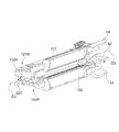
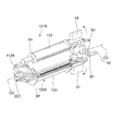
図1から図3に示したのは、本発明に係る吻合器を示す図であって、符号1は吻合器を、符号2R、2Lはクランプを示している。
また、図4、図5は、クランプ2Rを構成する一対のクランプ部材20R(クランプ部材21R及びクランプ部材25Rから構成される)、及びクランプ2Lを構成する一対のクランプ部材20L(クランプ部材21L及びクランプ部材25Lから構成される)を示す図であり、図6は、クランプ部材25Lを示す図である。
図1から図6に示した座標軸に付した符号R、L、Fr、Rr、U、Dは、吻合器1及びその構成部材に係る方向を示しており、吻合器1の後方側Rr(以下、手前側という)を手前に持った場合の右(R)、左(L)、Fr(先端側)、上側(U)、下側(D)を示している。A first embodiment of the present invention will be described below with reference to the drawings.
FIG. 1 to FIG. 3 are diagrams showing an anastomosis apparatus according to the present invention, in which
4 and 5 show a pair of
Reference numerals R, L, Fr, Rr, U, and D attached to the coordinate axes shown in FIG. 1 to FIG. 6 indicate directions related to the
吻合器1は、図1から図3に示すように、軸線O1R周りに回動可能なクランプ2Rと、軸線O1L周りに回動可能なクランプ2Lとを備えている。
クランプ2Rとクランプ2Lとは、それぞれ軸線O1R、O1L周りに回動可能とされている。As shown in FIGS. 1 to 3, the
The
また、クランプ2Rとクランプ2Lは、クランプ2Rに形成された軸線O1Rと直交する軸線O2と同軸に形成された連結孔23Rに、クランプ2Lに形成された軸線O1Lと直交する軸線O2と同軸に形成された連結ピン23Lを挿入することにより結合可能とされ、クランプ2Rとクランプ2Lとは、互いに軸線O2周りに回動可能とされている。
The
クランプ2Rとクランプ2Lとを連結し、軸線O2周りに回動して閉じた場合、クランプ2Rの軸線O1Rと、クランプ2Lの軸線O1Lは、一つの軸線O1上に配置されるようになっている。なお、軸線O1、軸線O2は、空間上の絶対座標を意味するのではなく、クランプ2R、2Lが閉じられて吻合器1を構成した場合における吻合器1を基準とする軸線である。
When the
クランプ2Rは、図4に示すように、クランプ部材21Rと、クランプ部材25Rとを備え、それぞれのクランプ部材21R、25Rは、吻合器1として用いる際に縫合方向に延在して形成されたフォークと、クランプ部材21R、25Rの長手方向に配置される器官把持機構3と、クランプ部材21R、25Rの長手方向と直交する断面において器官把持機構3の姿勢を変え、器官把持機構3が把持した器官組織の端部を外反させる外反機構5と、ファイアリング機構60及びアンビル部材67と、把持管理手段とを備えている。
また、クランプ部材21Rのクランプ面と、クランプ部材25Rのクランプ面とは、対向可能に構成されており、クランプ部材21Rとクランプ部材25Rとを閉じることにより、器官組織を挟むことが可能とされている。As shown in FIG. 4, the
The clamp surface of the
また、クランプ2Lは、図5に示すように、クランプ部材21Lと、クランプ部材25Lとを備え、それぞれのクランプ部材21L、25Lは、吻合器1として用いる際に縫合方向に延在して形成されたフォークと、クランプ部材21L、25Lの長手方向に配置される器官把持機構3と、クランプ部材21L、25Lの長手方向と直交する断面において器官把持機構3の姿勢を変え、器官把持機構3が把持した器官組織の端部を外反させる外反機構5と、ファイアリング機構60及びアンビル部材67と、把持管理手段とを備えている。
また、クランプ部材21Lのクランプ面と、クランプ部材25Lのクランプ面とは、対向可能に構成されており、クランプ部材21Lとクランプ部材25Lとを閉じることにより、器官組織を挟むことが可能とされている。Further, as shown in FIG. 5, the
Further, the clamp surface of the
なお、クランプ2Rとクランプ2Lとは、クランプ部材21R、25R、21L、25Lに設けられたそれぞれの外反機構5を全て外反操作した場合に、軸線O2周りに閉じることができるようになっている。
The
また、クランプ2Rとクランプ2Lとは、軸線O2周りに吻合器1を閉じたときに互いに対向する2組のクランプ部材対21、クランプ部材対25を構成するようになっている。
クランプ部材対21を構成するクランプ部材21Rとクランプ部材21Lの間、及びクランプ部材対25を構成するクランプ部材21Rとクランプ部材21Lの間の互いに対向する面は縫合対向面(縫合面)とされている。The
The mutually facing surfaces between the
吻合器1を構成した場合に、互いに対向するクランプ部材21Rとクランプ部材21L、及びクランプ部材21Lとクランプ部材21Rとの間には、ファイアリング機構60及びアンビル部材67を有する縫合機構がそれぞれ構成され、クランプ部材21R及びクランプ部材25Lにはファイアリング機構60が配置され、クランプ部材21L及び25Rにはアンビル部材67が配置されている。
When the
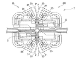
図6は、クランプ2Lのクランプ部材25Lに配置されるファイアリング機構60の概略構成を示す図であり、ファイアリング機構60は、ステープルSを収納するステープル収納部61と、射出部62とを備えている。
FIG. 6 is a diagram illustrating a schematic configuration of a
また、クランプ2Rのクランプ部材21R、25R、及びクランプ2Lのクランプ部材21L、25Lのそれぞれは、例えば、器官組織との反応が抑制される軽量なプラスチック樹脂の外観カバーにより被覆されている。
In addition, each of the
器官把持機構3は、図7に示すように、突刺歯部材(第1の把持歯板部材)31と、すくい歯部材(第2の把持歯板部材)35と、ハウジング39と、把持歯作動部材(把持歯動作部材)40と、係合ピン(第1係合部材、第2係合部材)43とを備え、前面側(縫合面側)から、ハウジング39、突刺歯部材31、すくい歯部材35、把持歯作動部材40の順に重ねて配置され、器官組織の縫合部近傍を把持するようになっている。また、ハウジング39は、突刺歯部材31と、すくい歯部材35を、突刺歯32の先端部32A及びすくい歯36の先端部36Aを含めて格納可能とされており、突刺歯32及びすくい歯36先端側の露出が抑制されるようになっている。
なお、この実施形態において、突刺し方向とは、突刺し歯が器官組織外側を押える方向(突刺し歯が移動する方向)を意味する。As shown in FIG. 7, the
In this embodiment, the piercing direction means the direction in which the piercing tooth presses the outside of the organ tissue (the direction in which the piercing tooth moves).
また、突刺歯部材31及びすくい歯36は、すくい歯36が突刺歯32に対して1ピッチ(突刺歯32の間隔)分手前側に後退した状態で配置されており、すくい歯36が1ピッチ前進したときにすくい歯36の先端部36Aが、1ピッチ先の突刺歯32の先端部32Aと略一致(合致)するようになっている。
Further, the piercing
突刺歯部材31は、板状の部材からなり、例えば、直針状に形成された複数の突刺歯32が櫛歯状に等ピッチに配列され、突刺歯32には第1係合切欠部33が形成されており、第1係合切欠部33には突刺歯32の配列方向の手前側(一方側)から先端側(他方側)に向かうにつれて突刺歯32から離間する側に傾斜する第1傾斜切欠部33Aとこの第1傾斜切欠部33Aから配列方向先端側に伸びる逃部33Bが形成されている。
The piercing
すくい歯部材35は、突刺歯部材31と並行して配置される板状の部材からなり、例えば、フック針状に形成された複数のすくい歯36が各突刺歯32と対応し、対応する突刺歯32と等ピッチに配列されるとともに、一方側から他方側に向かうにつれてすくい歯36から離間する側に傾斜する第2係合切欠部37が形成されている。この実施形態において、すくい歯36はその先端側がクランプ部材20R、20Lの先端側を向くように形成され、すくい歯36が突刺歯32に対して1ピッチ前進することで突刺歯32が突き刺した器官組織Pにすくい歯36が引っ掛けられて器官組織Pを把持するようになっている。
The
ハウジング39は、突刺歯部材31及びすくい歯部材35の前面側に配置され、突刺歯32及びすくい歯36の先端側の露出を抑制して、突刺歯32及びすくい歯36の損傷及び操作者との接触を抑制するようになっている。また、ハウジング39には、突刺歯32の配列方向に2本の長孔39Aが並んで形成され、長孔39Aに沿って係合ピン43が移動可能とされている。
The
把持歯作動部材40には、2つの係合ピン43が配設されており、操作ノブ41を操作することで、係合ピン43が突刺歯部材31、すくい歯部材35、ハウジング39に対してクランプ部材20R、20Lの手前側から先端側に相対移動するようになっている。
The gripping
第1傾斜切欠部33Aと、第2係合切欠部37と、係合ピン43とは、第1の駆動機構を構成し、係合ピン43が手前側から先端側に移動することで突刺歯32及びすくい歯36を矢印α方向に移動させてハウジング39の縁部39Eから露出させるようになっている。
The first
また、逃部33Bと、第2係合切欠部37と、係合ピン43とは、第2の駆動機構を構成し、係合ピン43が手前側から先端側に移動して逃部33Bに導入されるとともに第2係合切欠部37と係合して第2係合切欠部37の先端側の壁部を手前側から先端側に移動させることによりすくい歯部材35と突刺歯部材31とを突刺歯32の配列方向に相対移動させてすくい歯36を矢印β方向に移動させることによりすくい歯36と突刺歯32の位相を1ピッチ分変えるようになっている。
Further, the
なお、この実施形態において、第1の駆動機構と第2の駆動機構は、ともに操作ノブ41に連結されており操作ノブ41を操作することにより、突刺歯32に対してすくい歯36が長手方向に1ピッチ移動するとともにハウジング39の縁部39Eから露出するようになっている。
In this embodiment, the first drive mechanism and the second drive mechanism are both connected to the
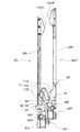
図8A、図8Bは、器官把持機構3の概略を示す図であり、把持歯作動部材40は連結部材44を介して連結ロッド12に接続され、連結ロッド12は、UBコネクタ13を介して連結部材13Bに接続され、連結部材13Bは操作ノブ41に接続されるようになっている。
8A and 8B are diagrams schematically showing the
また、把持歯作動部材40は、係合凸部40Aを介して、連結ロッド12の係合凹部12Gと係合されている。なお、係合凹部12Gは、長手方向の端面12Hの幅が係合凸部40Aよりもわずかに幅広に形成されている。
その結果、操作ノブ41が作動されて連結ロッド12が前後方向に移動することにより、把持歯作動部材40は、前後方向に移動して器官把持機構3の突刺歯32及びすくい歯36を把持状態とする一方で、外反機構5が操作される際には、外反操作ノブ51が回動されても、操作ノブ41が外反操作ノブ51と回動方向相対移動されて、操作ノブ41の回動が防止されるようになっている。The gripping
As a result, when the
連結ロッド12は、後述する外反操作ノブ51に軸方向に摺動可能に挿入されており、操作ノブ41を手前側から先端側(図8Aにおける右から左側)に移動させて図8Bのようにすることにより器官把持機構3において突刺歯32及びすくい歯36がハウジング39の縁部39Eから露出する方向に移動するようになっている。
また、連結ロッド12は、外反操作ノブ51に挿入される部分が、例えば、四角柱に形成されており、外反操作ノブ51を回動させると連結ロッド12が回動されて外反機構5が器官把持機構3の突刺歯32及びすくい歯36を外反状態になるように構成されている。
また、外反操作ノブ51の回動は、UBコネクタ13には伝達されないようになっている。The connecting
Further, the connecting
Further, the rotation of the
以下、図9A、図9B、図9Cを参照して器官把持機構3の作用を説明する。
まず、操作ノブ41を操作(図9Aにおける右から左側に移動)して、図9Aに示すように連結部材13Bを移動させると、連結ロッド12が前進して係合ピン43が突刺歯部材31の第1傾斜切欠部33A及びすくい歯部材35の第2係合切欠部37の傾斜部と係合させる。Hereinafter, the operation of the
First, when the
次に、図9Bに示すように連結部材13Bをさらに移動させると、係合ピン43が突刺歯部材31の第1傾斜切欠部33A及びすくい歯部材35の第2係合切欠部37の傾斜部に沿って移動し、突刺歯32及びすくい歯36が矢印α方向に移動してハウジング39の縁部39Eから露出する。
次いで、図9Cに示すように、係合ピン43が突刺歯部材31の逃部33Bに導かれるとともにすくい歯部材35の第2係合切欠部37と係合して第2係合切欠部37の先端側の壁部を押圧してすくい歯部材35と突刺歯部材31とが相対移動するとすくい歯36が矢印β方向に移動してすくい歯36と突刺歯32の位相が1ピッチ分変位する。Next, when the connecting
Next, as shown in FIG. 9C, the
なお、第1の把持歯板部材と第2の把持歯板部材とは、把持歯駆動部が、第1の把持歯板部材と第2の把持歯板部材の少なくともいずれか一方に接続されて、互いに相対移動可能とされた構成であってもよい。 The first gripping toothplate member and the second gripping toothplate member are such that the gripping tooth drive unit is connected to at least one of the first gripping toothplate member and the second gripping toothplate member. The configuration may be such that they can move relative to each other.
また、ハウジング39には、図10に示すように、前面(器官組織Pの端部がある)側に器官組織Pを吻合において縫合部から適切な間隔が確保されるように器官組織を切断刃Cにより切離して、縫合部に対応する位置(ここでは突刺歯32の先端部32A)から所定の間隔Kをあけた位置を断端部とするためのカットプロテクタ(器官組織を切離するためのガイド)39Bが形成されている。
In addition, as shown in FIG. 10, the
切断刃(例えば、メス)Cを、カットプロテクタ39Bに沿って移動させることにより、切断刃C先端の切断部C1は、クランプ面に挟んだ状態の器官組織Pを、突刺歯32の先端部32Aから所定の間隔Kをあけた縫合部近傍(例えば、最適とされる位置)で容易に切離することができる。
その結果、器官組織Pの縫合部近傍の余剰又は不足を抑制して器官組織Pの吻合を安定かつ効率的に行なうことができる。なお、カットプロテクタ39Bは、突刺歯32の伸びる方向に対して把持歯先端部側が10°から45°の範囲で交差することが好適である。By moving the cutting blade (for example, a knife) C along the
As a result, surplus or deficiency in the vicinity of the sutured portion of the organ tissue P can be suppressed, and the anastomosis of the organ tissue P can be performed stably and efficiently. The
また、図11Aに示すように、各クランプ2R、2Lは、例えば、いずれか一方のクランプ部材のUBコネクタ13に同期用凸部45Aが形成され、UBコネクタ13に対応して他方のクランプ部材に配置されたコネクタ14には同期用凹部45Bが形成されている。
同期用凸部45Aと、同期用凹部45Bとは、器官把持機構3を、同期して移動させる把持動作同期手段45を構成する。
その結果、図11Bに示すように、クランプ2R、2Lを閉じて同期用凸部45Aを同期用凹部45Bに挿入することにより対向する2つの器官把持機構3が、器官組織Pをクランプ面に挟んだ状態で同期して駆動され、突刺歯32及びすくい歯36が同期して駆動するようになっている。In addition, as shown in FIG. 11A, each
The synchronization
As a result, as shown in FIG. 11B, the two
外反機構5は、遠隔操作により器官把持機構3を外反操作する外反操作ノブ(外反操作部)51と、連結ロッド12が、フォークの長手方向を横切って回動することにより吻合器1の長手方向に沿う軸線方向から見た場合の姿勢が変化するリンク53により、器官把持機構3が、縫合部近傍を突刺す外反前位置から器官組織の縫合部が縫合面に位置する外反後位置に至る外反移動範囲を移動するように構成されている。なお、例えば、外反操作ノブ51とクランプ部材21R、21L、25R、25Lとの間には、外反機構5を外反前位置、及び外反後位置において係止するための図示しない、係合部が設けられており、これら係合部は、把持管理手段を構成する。
The
外反操作ノブ51は、外反操作をした場合に外反操作ノブ51に形成されたロック凸部(図示せず)が入り込むロック凹部が形成されていて、外反操作ノブ51を回動させた場合に、ロック凸部がロック凹部に係合して器官把持機構3の突刺歯32及びすくい歯36が露出された位置で保持されるとともに、器官把持機構3が外反後位置にて保持されて外反状態が維持されるようになっている。
The
リンク53は、この実施形態では、図12A、図12Bに示すように4つの複数(4つ以上)のリンク53A、53B、53C、53Dにより構成されており、リンク53Aは、一方端を吻合器1の本体側に形成され連結ロッド12の回転軸線と一致して形成される支点J1とし、他方端をリンク部材52Bに形成される支点J2とする支点J1、J2間に形成されており、外反操作ノブ51により連結ロッド12を回動させることによりリンク53の姿勢を変えてハウジング39を外反させるようになっている。
In this embodiment, the
また、リンク53Bは一方端をリンク部材52Bに形成される支点J2とし他方端をハウジング39に形成される支点J3とする支点J2、J3間に形成され、リンク53Cは一方端をハウジング39に形成される支点J3とし他方端を同じくハウジング39に形成される支点J4とする支点J3、J4間に形成され、リンク53Dはそれぞれハウジング39に形成される支点J4及び支点J1間に形成されている。
この実施形態において、外反機構5は、リンク53A、53B、53C、53Dにより形成される四角形のリンク53とされている。The
In this embodiment, the
図13は、リンク53からなる外反機構5による器官組織Pの外反軌跡を示す図であり、上記構成とすることにより、外反操作ノブ51を回動することで器官把持機構3により把持した器官組織Pを小さな力でスムースに外反させることができ、簡単な構造により、外反に際して器官組織Pに無理な伸張力が加わるのを抑制して器官組織Pの負担を軽減することができる。
なお、外反機構5を構成するリンクについては、4つ以上のリンクから構成される他の機構を用いてもよい。FIG. 13 is a diagram showing the valgus locus of the organ tissue P by the
In addition, about the link which comprises the
また、吻合器1を構成するクランプ2R、2Lは、外反に際して、外反操作ノブ51を回動させることにより一対のクランプ部材20R、20Lの間隔を所定間隔に調整、保持するクランプ部材間隔維持手段を備えている。
クランプ部材間隔維持手段は、図14A、図14Bに示すように、例えば、クランプ2を構成するいずれかの一方のクランプ部材20の先端側に設けられたフォーク連結部材22と、他方のクランプ部材20に配置され器官把持機構3の連結ロッド12とを備えており、フォーク連結部材22には連結ロッド12の先端部12Aを収納する収納空間が形成されている。In addition, the
As shown in FIGS. 14A and 14B, the clamp member interval maintaining means includes, for example, a
連結ロッド12の先端部12Aは、先端側の一方の側面にテーパが形成されるとともに他方の側面に平面部が形成されており、フォーク連結部材22の収納空間は、外反されていない状態の連結ロッド12の先端部12Aが収容空間に容易に挿入可能とされるとともに器官把持機構3が外反された場合に先端部12Aの平面部により押圧される内壁面が形成されている。
The
その結果、クランプ2を閉じた状態で連結ロッド12を前進させて器官把持機構3を作動させた場合、図14Aに示すように先端部12Aがフォーク連結部材22の収容部にスムースに挿入される。
その状態で、外反操作ノブ51により連結ロッド12を回動させると、図14Bに示すように先端部12Aのテーパの向きが変わって先端部12Aの平面部が収容部の内壁面と当接して一対のクランプ部材20R、20Lの間隔を所定間隔に調整、保持する。As a result, when the connecting
In this state, when the connecting
また、各クランプ2は、器官把持機構3が外反後位置側に移動した場合に、突刺歯部材31とすくい歯部材35が相対移動しないように管理して、外反した器官組織Pが器官把持機構3からはずれるのを抑制するための把持管理手段を有している。
In addition, each
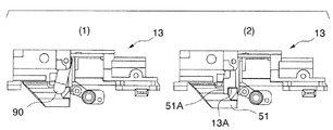
この把持管理手段は、UBコネクタ13に形成された係止凹部13Aと、外反操作ノブ51の外反操作における外反操作ノブ51の回動方向前方側に形成された係止凸部51Aとを備え、外反操作ノブ51を回動させて外反操作した場合に係止凸部51Aが係止凹部13Aに挿入されることにより実現されるようになっている。
The grip management means includes a
具体的には、図15A(1)、(2)に示すように、突刺歯32及びすくい歯36により器官組織Pを把持するために器官把持機構3を前進させるとUBコネクタ13も前進する。
次に、図15B(1)、(2)に示すように、UBコネクタ13が前進すると係止凹部13Aが外反操作ノブ51の係止凸部51Aに対応する位置に到達する。
次いで、図15C(1)、(2)に示すように、ノブ51を回動させて外反状態とすると、係止凸部51Aが係止凹部13Aに挿入されてUBコネクタ13の後退が抑制される。
なお、図15A(1)、図15B(1)、図15C(1)は、リリース部材90のUBコネクタ13に対する向きを示す図であり、図15A(2)、図15B(2)、図15C(2)は、外反操作ノブ51の係止凸部51Aとの相対的位置を示す図でありリリース部材90を省略している。また、図15A(2)、図15B(2)において二点鎖線で示した外反操作ノブ51は、係止凸部51Aと係止凹部13Aの相対位置を概念的に示したものである。Specifically, as shown in FIGS. 15A (1) and (2), when the
Next, as shown in FIGS. 15B (1) and (2), when the
Next, as shown in FIGS. 15C (1) and 15 (2), when the
15A (1), FIG. 15B (1), and FIG. 15C (1) are views showing the orientation of the
その結果、UBコネクタ13の後退が抑制され、外反された状態の器官組織Pから突刺歯32及びすくい歯36がはずれるのが抑制されて外反状態における器官組織Pを安定して把持することができる。
なお、かかる外反状態の器官組織Pを安定して把持する機構については、他の機構によって実現してもよいし、かかる機構の設定については任意に選択可能である。As a result, the retreat of the
Note that the mechanism for stably grasping the organ tissue P in the valgus state may be realized by another mechanism, and the setting of the mechanism can be arbitrarily selected.
縫合機構は、図1、図2に示すように、クランプ2Rを構成しているクランプ部材21Rとクランプ部材25R、及びクランプ2Lを構成しているクランプ部材21Lとクランプ部材25Lのうち、相手側のクランプ2R、2Lとの間で互いに対向可能とされる2組のクランプ部材対21、25間に構成されており、2組の縫合機構は、それぞれファイアリング機構60と、アンビル部材67とを備えている。
As shown in FIGS. 1 and 2, the suturing mechanism includes a
図16、図17はファイアリング機構60を、図18A、図18Bは縫合機構の作用を説明する図である。
ファイアリング機構60は、図4、図5に示したようにクランプ2Rに配置される上側ファイアリング機構60Rと、クランプ2Lに配置される下側ファイアリング機構60Lとを備え、それぞれのファイアリング機構60は、射出部62と、図18Aに示すようなステープルSを保持するステープル収納部61とを備えている。16 and 17 illustrate the
The
また、射出スライダ63R、63Lは、図16に示すように、吻合器1において上側の縫合機構を構成する射出スライダ63Rは、クランプ2Rのクランプ部材21Rを構成するためのフレーム11Rに設けられ、下側の縫合機構を構成する射出スライダ63Lは、クランプ2Lのクランプ部材25Lを構成するためのフレームに設けられている。
Further, as shown in FIG. 16, the
この実施形態において、ファイアリング機構60はクランプ部材対21、25のうちクランプ部材(一方のクランプ部材)21R、25Lに配置され、アンビル部材67はクランプ部材(他方のクランプ部材)21L、25Rに配置されている。
In this embodiment, the
すなわち、図4に示すように、クランプ2Rでは、例えば、操作者が吻合器1を持った場合における上側を縫合するための上側ファイアリング機構60Rがクランプ部材21Rに配置されるとともに、クランプ2Lに配置される下側ファイアリング機構60Rと対応するアンビル部材67Rがクランプ部材21Rに配置されている。
また、図5に示すように、クランプ2Lでは下側ファイアリング機構60Lがクランプ部材25Lに配置されるとともにアンビル部材67Lがクランプ部材21Lに配置されている。That is, as shown in FIG. 4, in the
Further, as shown in FIG. 5, in the
ステープル収納部61は、ステープルSの形状及び配列に対応する複数の保持孔(図示せず)を有しており、この実施形態において、保持孔はそれぞれのクランプ部材21R、25Lの長手方向に沿って上下2列のステープルSの列が並列に配置されるように形成されていている。
The
射出部62は、図18A、図18Bに示すように、射出スライダ63と、射出スライダ63の先端部に形成されるスライダヘッド63Hと、図16、図17に示すような射出スライダ63に入力する射出ノブ64と、ノックアウト65とを備えている。
また、射出スライダ63は、射出スライダ63Rと、射出スライダ63Lとを備えている。As shown in FIGS. 18A and 18B, the
The
ステープルSは、強度、耐腐食性が高く、生体反応を発生し難い材料、例えば、チタン等によって構成され、「コ」の字型に形成されており、中央軸部に対して屈曲された両側の針部が、中央軸部の中央側に向かって折り曲げられることで重ね合わせた器官組織Pを互いに係止して縫合するようになっている。 The staple S is made of a material that has high strength and corrosion resistance and hardly generates a biological reaction, such as titanium, and is formed in a “U” shape, and is bent on both sides with respect to the central shaft portion. These needle portions are bent toward the center side of the central shaft portion, so that the stacked organ tissues P are locked and sutured together.
それぞれのアンビル部材67は、図18Aに示すように、射出されたステープルSの両側の針部を中央軸部の中央側に向かって折り曲げて成形するための成形凹部の列を2列備えており、ステープル収納部61R、61Lのそれぞれに対応して配置されている。
As shown in FIG. 18A, each
縫合機構は、図18Aに示すように、射出スライダ63を前進させることによりスライダヘッド63Hがノックアウト65のテーパ部を押圧してステープル収納部61に収納されたステープルS側に前進させ、ステープルSをアンビル部材67に向かって順次射出するようになっている。
As shown in FIG. 18A, the suturing mechanism moves the
また、図16、図17に示すように、射出スライダ63Rの射出ノブ64Rの進行方向前方側(射出時の移動方向)には、射出ノブ64Rから射出ノブ64Lの前方に伸びるスライダガイド64Sが形成され、このスライダガイド64Sはフレーム11Rに対応するクランプ部材21Lのフレーム(図示せず)に形成されたガイドと係合して射出ノブ64Rが前進後退する際の横ブレを抑制するようになっている。
また、このスライダガイド64Sは射出順序管理手段を構成しており、射出スライダ63Lが射出スライダ63Rより先行して前進すること、及び射出スライダ63Rが原点位置(作動前の位置)にある場合の射出スライダ63Lの前進を阻止するようになっている。As shown in FIGS. 16 and 17, a
Further, the
その結果、吻合における操作手順が、射出スライダ63Rにより上側を縫合し、後から下側を縫合する順序である場合に、誤操作の発生を抑制することができる。
また、射出スライダ63Lの射出ノブ64Lの進行方向後方側には、図17に示すように、スライダガイド64Tが形成されており、このスライダガイド64Tは、クランプ部材25Lとクランプ部材25Rが閉じられた場合にフレームとこれに対応するフレーム(図示せず)との間に形成されるガイド用の間隙と係合することにより射出ノブ64Lが前進後退する際の横ブレを抑制するようになっている。As a result, when the operation procedure in the anastomosis is an order in which the upper side is stitched by the
Further, as shown in FIG. 17, a
また、射出ノブ64R、64Lには、それぞれロックノブ64P、64Qが形成されていて、射出ノブ64R、64Lは、このロックノブ64P、64Qを押してロックノブ64P、64Qに形成された係合部がフレームのガイド部に形成された切欠(例えば、フレーム11Rにおいては切欠11P)との係合が解除された場合に射出ノブ64R、64Lが前進可能とされている。
その結果、射出ノブ64R、64Lそれぞれの前進を誤操作することが抑制されるようになっている。The injection knobs 64R and 64L are formed with
As a result, erroneous operation of the forward movement of each of the injection knobs 64R and 64L is suppressed.
また、縫合機構にはフローティング機構68が設けられており、このフローティング機構68は、図18Bに示すように、アンビル部材67をクランプ2に設けるためのアンビル取付穴67Aの径を取付ネジ67Bよりもわずかに大きく形成することにより構成され、ステープル収納部61に対するアンビル部材67の相対的位置の所定の範囲内で調整可能とされている。
The suturing mechanism is provided with a floating
なお、この実施形態においては、フローティング機構68がアンビル部材67側に設けられステープル収納部61が固定されている場合について説明したが、フローティング機構68をステープル収納部61とアンビル部材67のいずれに設けるかは自在に設定可能であり、フローティング機構68をステープル収納部61側に設けてもよいし、ステープル収納部61とアンビル部材67の双方に設けてもよい。
In this embodiment, the floating
また、縫合機構は、ステープル収納部61の縫合対向面に、図18Bに示すような位置決ピン61A(位置決手段)が設けられるとともに、アンビル部材67の縫合対向面には位置決孔(位置決手段)66Aが形成されており、位置決ピン61Aが位置決孔66Aに挿入されることによりステープル収納部61とアンビル部材67との相対的位置が保持されるようになっている。
Further, the suturing mechanism is provided with a
かかる構成により、縫合機構にアライメントずれ等がある場合にも把持した器官組織PにステープルSを安定して形成することができ、例えば、ステープル成形不良や縫合不良の発生が抑制される。 With this configuration, the staple S can be stably formed on the grasped organ tissue P even when there is misalignment or the like in the suturing mechanism, and, for example, the occurrence of staple forming failure or suturing failure is suppressed.
また、吻合器1は、先行射出部ロック手段を備え、2組の縫合機構のうち先に作動させた射出部を射出終了位置でロックして移動不能とするようになっている。
この実施形態において、先行射出部ロック手段は、図19A〜図19D、図20A〜図20Eに示すような射出スライダ63Rに形成されたスライダロック用凹部75と、吻合器本体に設けられたスライダロック部材71とを備えている。In addition, the
In this embodiment, the preceding injection portion locking means includes a
スライダロック部材71は、例えば、プラスチック等の樹脂により形成され吻合器1に取付けるための取付孔が形成された部材本体から周囲に向かって伸びる3つのアームを備えており、3つのアームはそれぞれロック部71A、付勢部71B、解除ピン部71Cとされていて、付勢部71Bが弾性変形することにより、ロック部71A、解除ピン部71Cの取付孔を中心とする向きが変化するようになっている。
The
先行射出部ロック手段は、射出スライダ63Rを前進させた場合にその前進端位置においてスライダロック部材71のロック部71Aが、射出スライダ63Rのスライダロック用凹部75と係合して射出スライダ63Rをロックして射出スライダ63Rの前進後退をさせないようになっている。
When the
以下、図19A〜図19Dを参照して、先行射出部ロック手段の作用を説明する。
まず、図19Aに示すように、クランプ部材対21によりクランプされた吻合器1上側の器官組織Pを縫合するために射出スライダ63Rを前進させる。
前進させた射出スライダ63Rが前進端に到達すると、図19Bに示すように、スライダロック用凹部75にロック部71Aが係合して射出スライダ63Rが移動不能となる。この状態は、射出スライダ63Lが前進端に移動した後、後退するまで維持される。
次に、図19Cに示すように、クランプ部材対25によりクランプされた吻合器1の下側の器官組織Pを縫合するために射出スライダ63Lを前進させる。
次いで、図19Dに示すように、射出スライダ63Lを後退させるとロック部71Aがスライダロック用凹部75からはずれて射出スライダ63Rがスライド可能となる。Hereinafter, with reference to FIGS. 19A to 19D, the operation of the preceding injection unit locking means will be described.
First, as shown in FIG. 19A, the
When the
Next, as shown in FIG. 19C, the
Next, as shown in FIG. 19D, when the
また、吻合器1は、射出部ロック解除手段を備えており、後に作動させる射出スライダ63をステープルSの射出終了後に原点位置側に移動させることで、先に移動され先行射出部ロック手段により係止された射出スライダ63のロックを解除して移動可能とするようになっている。
Further, the
この実施形態において、射出部ロック解除手段は、射出スライダ63Lに形成された解除溝部80とスライダロック部材71とを有している。
射出部ロック解除手段は、図19A〜図19D、図20A〜図20Eに示すように、2組の縫合機構のうち、射出スライダ63R(一方の射出部)を先行して作動させた場合に、射出スライダ63L(他方の射出部)を作動させてその後双方の射出スライダ63R、63Lを原点位置に戻す際に原点位置側に移動させることにより突刺歯32及びすくい歯36が後退して器官把持機構3の把持が解除されるようになっている。
なお、先行して作動させた射出スライダ63Rを射出部ロック解除手段によりロック解除する場合の射出スライダ63Lは、後退端とすることが操作上好適である。In this embodiment, the injection portion lock releasing means has a
As shown in FIGS. 19A to 19D and FIGS. 20A to 20E, the injection unit unlocking means, when the
Note that it is preferable in terms of operation that the
射出スライダ63Lには、図17、図19A〜図19D、図20A〜図20Eに示すように、ロック解除ピン部71Cと係合してロック部71Aをスライダロック用凹部75から解除するため解除溝部80が形成されている。
解除溝部80は、図17、図19A〜図19D、図20A〜図20Eに示すように、射出スライダ63Lの上面に形成されたピン導入部81と、傾斜部82と、変形保持部83とを有している。As shown in FIGS. 17, 19A to 19D, and 20A to 20E, the
As shown in FIGS. 17, 19A to 19D, and 20A to 20E, the
以下、図20A〜図20Eを参照して、射出部ロック解除手段の作用について説明する。なお、便宜のため、図20においてスライダガイド64Sは図示していない。
まず、図20Aに示すように、吻合器1の下側にクランプした器官組織Pを縫合するために射出スライダ63Lを前進させる。
次に、図20Bに示すように、射出スライダ63LによるステープルSの射出が終了すると、解除溝部80のピン導入部81にロック解除ピン部71Cが近接する。
次いで、図20Cに示すように、射出スライダ63Lが前進端に近づくと解除溝部80のピン導入部81と傾斜部82との間に形成される壁部の後方側の先端にロック解除ピン部71Cが近づく。
次に、図20Dに示すように、射出スライダ63Lが前進端に到達するとロック解除ピン部71Cがピン導入部81から傾斜部82に移動可能となる。
次いで、図20Eに示すように、射出スライダ63Lを後退するとロック解除ピン部71Cは傾斜部82に沿って射出スライダ63Lの外方(図20Eにおける上)側に移動する。
その結果、スライダロック部材71の付勢部71Bが変形して、ロック部71Aがスライダロック用凹部75から離間する側に変形して射出スライダ63Lのロックが解除される。Hereinafter, with reference to FIG. 20A to FIG. 20E, the operation of the injection unit unlocking means will be described. For convenience, the
First, as shown in FIG. 20A, the
Next, as shown in FIG. 20B, when the ejection of the staple S by the
Next, as shown in FIG. 20C, when the
Next, as shown in FIG. 20D, when the
Next, as shown in FIG. 20E, when the
As a result, the urging
また、吻合器1は、把持解除機構(ロック解除手段)を有している。
図21Aから図24Eは、把持解除機構を説明する図である。
把持解除機構は、リリース部材90と、射出スライダ63Rに形成されたリリース部材制御部95と、UBコネクタ13に形成され係合ピン93が係合可能とされた係合凹部13Cとを備えている。The
FIG. 21A to FIG. 24E are diagrams illustrating the grip release mechanism.
The grip release mechanism includes a
UBコネクタ13は、図21A、図21Bに示すような把持解除機構を構成する係合凹部13Cを備え、係合ピン93が係合可能とされている。
また、UBコネクタ13は、図21Bに示すように、上のクランプ部材21R、21Lと下のクランプ部材25R、25Lを閉じた状態でロックするための上下ロック27を構成している。The
Further, as shown in FIG. 21B, the
上下ロック27は、係合凸部28と、解除ノブ29とを備えている。
係合凸部28は、下側クランプ部材25R、25Lに配置され、解除ノブ29は、上側のクランプ部材21R、21Lに配置されている。
係合凸部28は、上側のクランプ部材21R、21L側に向かって伸びる板状部材からなり、クランプ2R、2Lの軸線O1R、O1Lと平行に形成された複数の係合溝28Aを有している。The
The engagement
The engagement
解除ノブ29は、係合凸部28と係合して上下ロックを作動させるとともに、ロックされた上下ロック27を解除するためのものであり、係合凸部28が挿入される孔を形成する壁部29Aと、係合凸部28をロックする係止部材28Bとを有している。
The
係止部材28Bが係合溝28A側に付勢されており、係止部材28Bの先端に形成された係合凸部29Cが係合溝28Aに係合することにより、クランプ2R、2Lを閉じた状態でロックするようになっている。
また、解除ノブ28を付勢方向に反して移動させることにより、係合溝28Aに対する係合凸部29Cの係合が解除され、上下ロック27が解除されるようになっている。The locking member 28B is urged toward the engaging
Further, by moving the
リリース部材90は、長円形に形成されたリリース部材本体91の一方の端部の一方側の面に吻合器1に対して回動可能に設けられる回動ピン92が形成され、他方側の端部の回動ピン92が形成されたのとは反対側の面に係合ピン93が形成されており、吻合器1とは回動ピン92を介して連結されている。
The
図22A、図22Bは、リリース部材制御部95を説明する図であり、図22Aは側面図を、図22Bは射出スライダ63Rの下側の面を示す平面図である。リリース部材制御部95は、射出スライダ63Rの下側の面に形成され、射出スライダ63Rの後方側が射出スライダ63Rの下面から離れて漸次高くなるリリース部材変形傾斜部96と、リリース部材変形傾斜部96の後方側に形成されたリリース部材復元段差部97と、射出スライダ63Rが後退することで射出スライダ63Rとほぼ直交して配置されたリリース部材90の係合ピン93を射出スライダ63Rの移動方向(後退方向)に向かって回動される傾斜部98とを備えている。
22A and 22B are diagrams illustrating the release
図23A〜図23D、図24A〜図24Eは、把持解除機構の作用を説明する図であり、図23A〜図23Dはリリース部材90の動作を、図24A〜図24Eはリリース部材90による器官把持機構3の解除を説明する図である。
まず、図23Aに示すように射出スライダ63Lを前進させる。
次に、図23Bに示すように、射出スライダ63Lのリリース部材制御部95がリリース部材90まで前進すると、リリース部材制御部95のリリース部材変形傾斜部96にリリース部材本体91が乗り上がる。この場合、リリース部材本体91が変形するのでリリース部材90は回動されることはない。
次いで、図23Cに示すように、変形したリリース部材90がリリース部材制御部95のリリース部材復元段差部97が到達すると、リリース部材本体91がリリース部材変形傾斜部96からリリース部材復元段差部97に落ちてリリース部材本体91の変形がなくなる。このように射出スライダ63Lが前進する場合にはリリース部材90は回動しない。
次いで、図23Dに示すように射出スライダ63Lが後退すると、リリース部材90が傾斜部98により回動される。その結果、リリース部材90の係合ピン93がUBコネクタ13の係止凹部13Aに挿入される。23A to 23D and FIGS. 24A to 24E are views for explaining the operation of the grasp release mechanism. FIGS. 23A to 23D show the operation of the
First, as shown in FIG. 23A, the
Next, as shown in FIG. 23B, when the release
Next, as shown in FIG. 23C, when the
Next, as shown in FIG. 23D, when the
図24A〜図24Eは、把持解除機構におけるリリース部材90の作用を説明する図である。
まず、図24Aに示すように、器官把持機構3を作動させるために操作ノブ41を前進する。
図24Bは、器官把持機構3において、例えば、突刺歯32及びすくい歯36がともに移動して露出される場合の位置を示しており、図24Cはすくい歯36が前進端に到達して器官組織Pを把持した位置(戻り方向の矢印は除く)にUBコネクタ13が前進した場合を示している。24A to 24E are views for explaining the action of the
First, as shown in FIG. 24A, the
FIG. 24B shows a position in the
この図24A、図23Bを経て、UBコネクタ13が図24Cに示した位置に到達するまでの間、及び図23A、図23Bを経て図23Cの状態に到達するまでのリリース部材本体91が変形してリリース部材90がリリース部材制御部95を乗り越えるまでの間、リリース部材90は回動することはない。
The release member
次に、図24Cに示すように、図23B、図23Cにおけるリリース部材制御部95によりリリース部材90が回動を開始する。
次いで、図24Dに示すように、リリース部材90が回動してリリース部材90の係合ピン93がUBコネクタ13の係合凹部13Cとの係合を開始し、UBコネクタ13を介して器官把持機構3の連結ロッド12を後退させる。その結果、突刺歯32及びすくい歯36がハウジング39内に下がってゆく。
そして、図24Eに示すように、リリース部材90が回動端に到達するまで回動され、UBコネクタ13がその位置まで後退すると器官把持機構3による器官組織Pの把持が解除される。Next, as shown in FIG. 24C, the
Next, as shown in FIG. 24D, the
Then, as shown in FIG. 24E, the
以上のように、リリース部材90がUBコネクタ13の係合凹部13Cと係合してUBコネクタ13を後退させることにより、外反機構5を外反前の元位置まで戻すことなく器官組織Pから突刺歯32及びすくい歯36がはずれるため、吻合された器官組織Pの突合せ状態を維持したまま吻合器1からはずすことができる。
As described above, the
具体的な作用を、図25A〜図25Dを参照して説明する。
まず、射出スライダ63Lを前進させて縫合を終えた状態では、図25Aに示すとおり、UBコネクタ13の係止凹部13Aに係止凸部51Aが挿入された状態であり図15C(1)、図15C(2)と同等の状態である。
次に、射出スライダ63Lを後退させてリリース部材90が回動(図23C、図23D参照)すると、図25B(1)、(2)に示すように係合ピン93が係止凸部51Aに当接して係止凸部51Aが係止凹部13Aから抜ける方向に押圧され、リリース部材90が所定の角度まで回動すると図25Cに示すように係止凸部51Aが係止凹部13Aから抜ける。
その結果、UBコネクタ13の後退に際して外反操作ノブ51を元に戻すことなく、図25D(1)、(2)に示すように、係止凸部51Aが係止凹部13Aから抜けてUBコネクタ13が後退することができる。
ここで、図25B(1)は図25B(2)のX−X断面を、図25D(1)は図25D(2)のY−Y断面を示したものである。A specific operation will be described with reference to FIGS. 25A to 25D.
First, in a state where the
Next, when the
As a result, when the
Here, FIG. 25B (1) shows the XX cross section of FIG. 25B (2), and FIG. 25D (1) shows the YY cross section of FIG. 25D (2).
以下、図26Aから図34を参照して、吻合器1の作用について説明する。
まず、クランプ2において対向する一対のクランプ面の間に、筒状の器官組織Pの端部近傍を偏平にしてマーカー(図示せず)を目安にして配置し、クランプ2を軸線O1周りに回動して挟み、操作ノブ41を操作する。そうすると、図26A、図26Bに示すように、器官組織Pに突刺歯32を突き刺すとともにすくい歯36により器官組織Pを引っ掛けて把持する。Hereinafter, the operation of the
First, the vicinity of the end of the tubular organ tissue P is flattened between a pair of opposing clamp surfaces in the
ここでは、患部を切除した筒状組織の端部近傍を把持する場合を示しているが、患部を切除し端部を形成する前の筒状の器官組織をクランプし、その後に患部を切除することが一般的な手技手順である。 Here, the case is shown in which the vicinity of the end of the cylindrical tissue from which the affected part has been excised is shown, but the affected part is excised and the tubular organ tissue before the end is formed is clamped, and then the affected part is excised. This is a general procedure.
次に、図27、図28に示すように、外反操作ノブ51を操作して外反機構5のリンク53の姿勢を変えて器官組織Pの端部近傍を外反させる。
図29、図30は、その途中過程を示している。
次いで、図31に示すように、外反操作ノブ51をさらに回動して器官組織Pの端部近傍を外反の終了位置まで移動させる。Next, as shown in FIGS. 27 and 28, the
29 and 30 show the intermediate process.
Next, as shown in FIG. 31, the
次いで、2組のクランプ2R、2Lを、軸線O2周りに回動させて、図32に示すようにクランプ2R及びクランプ2Lを対向させるとともにこれらクランプ2R、2Lにより外反された器官組織Pの開口部近傍の端部を突き合せる。
このとき、先端側に設けられたフォーク結合フックNにより、クランプ2R及びクランプ2Lを充分に重ね合わせる。Next, the two sets of
At this time, the
次に、左右のファイアリング機構60を操作して、図33に示すように突き合わせた器官組織P同士をステープルSによって縫合する。
縫合は、それぞれの射出ノブ64R、64Lを操作してそれぞれの射出スライダ63R、63Lを順番にスライドさせることにより行なわれ、それぞれのスライダヘッド63Hが前進して対応するノックアウト65を前進させてステープル収納部61からステープルSをアンビル部材67に向かって射出するとともに針部を折り曲げて成形することで行なわれる。Next, the left and
Stitching is performed by operating the ejection knobs 64R and 64L to slide the
次に、図34に示すように、射出スライダ63L及び射出スライダ63Rを順番に後退させることで器官把持機構3の突刺歯32及びすくい歯36が後退して、突刺歯32及びすくい歯36が器官組織Pから離れる。
この状態で、クランプ2R、2Lを開き、その後、クランプ2R及びクランプ2Lを軸線O2周りに回動させて吻合器の各クランプ部材21R、21L、25R、25Lを器官組織Pから分離させる。Next, as shown in FIG. 34, the
In this state, the
なお、上記第1の実施の形態においては、突刺歯32が、ほぼ突刺し方向に延在する場合について説明したが、例えば、突刺歯32に代えて、図35A、図35Bに示すように、突刺歯232がすくい歯236側にわずかに傾いて延在する構成としてもよく、かかる構成を採用することにより、突刺しを容易に行ない、すくい歯236とともに器官組織Pを充分に把持することができる。
In the first embodiment, the case where the piercing
また、例えば、図36A、図36Bに示すように、突刺歯332を、すくい歯336のように曲線的に形成して、先端部332Aがすくい歯336側に漸次変位するように形成してもよく、かかる構成を採用することにより、器官組織Pを傷つけることが抑制され、また、器官組織をつまむようにして確実に把持することができる。なお、先端部がすくい歯側に漸次変位する構成において、すくい歯336以外の形状を採用してもよい。
Further, for example, as shown in FIGS. 36A and 36B, the piercing
クランプ部材21R、21L、25R、25Lによれば、外反操作ノブ51により、器官把持機構3を構遠隔操作よって、外反前位置、外反後位置にて保持することができるので、外反操作を容易に行なうことができ、器官把持機構3を外反前位置及び外反後位置にて確実に保持して、安定した外反操作を行なうことができる。
According to the
クランプ102R,102Lによれば、クランプ2によりクランプした器官組織Pをほぼ同一の厚さに維持することができるので器官組織Pを安定して把持するとともに縫合することができる。
According to the
また、把持管理手段を備えているので、器官把持機構3を外反前位置と外反後位置のそれぞれにおいて保持し、器官把持機構3が外反後位置側に移動した場合に、外反後に器官組織Pが、突刺歯32及びすくい歯36から外れることが抑制され、把持した器官組織Pを安定して保持することができる。
In addition, since the grip management means is provided, the
また、クランプ部材21R、21L、25R、25Lによれば、突刺歯32及びすくい歯36がハウジング39に収納されるので、突刺歯32及びすくい歯36の先端部32A、36Aが外部の物体と接触して破損するのが抑制される。
その結果、医療従事者等の操作者が、容易、安全かつ効率的に取り扱うことができる。
また、破損した突刺歯32、すくい歯36により器官組織Pを損傷することが抑制される。Further, according to the
As a result, an operator such as a medical worker can easily, safely and efficiently handle it.
In addition, damage to the organ tissue P by the damaged piercing
クランプ2R、2Lによれば、挟んだ器官組織Pを、それぞれのクランプ部材の器官把持機構3、外反機構5によって、容易かつ効率的に把持及び外反することができる。
また、クランプ2R、2Lによれば、上下の対応する器官把持機構3を同期して作動するので、器官組織Pを上下から同時に把持することができ、器官組織Pを安定して把持することができる。According to the
Further, according to the
吻合器1によれば、離間管理手段を備えていて、2つの射出部がともに原点位置にある場合に限定して、クランプ2R、2Lを開くことが可能とされるので、器官組織Pの損傷を抑制することができる。
According to the
吻合器1によれば、二つの射出ノブ64R、64Lがともに作動して吻合が完了するまで、器官把持機構3により器官組織Pが確実に把持され、かつクランプ面に挟持されるので、安定した吻合を行なうことができる。
According to the
吻合器1によれば、解除ノブ29を作動させることにより、上下ロック27及び器官把持機構3による把持を、容易に解除することができ、かつ吻合時の複雑な手順、並びに誤操作に起因する器官組織Pの損傷を抑制し、一連の操作手順を容易かつ安全に遂行することができる。
以上のように、吻合器1によれば、器官組織Pの吻合を効率的かつ安定して行なうことができる。According to the
As described above, according to the
次に、本発明の第2の実施形態について、図面を参照して説明する。
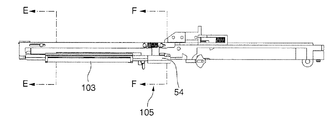
図37、図38に示したのは、本発明に係る吻合器を示す図であって、符号101は吻合器を、符号102R、102Lはクランプを示している。Next, a second embodiment of the present invention will be described with reference to the drawings.
FIG. 37 and FIG. 38 are views showing an anastomosis apparatus according to the present invention, in which reference numeral 101 indicates an anastomosis apparatus and
また、図39、図40は、クランプ102Rを構成する一対のクランプ部材120R(クランプ部材121R及びクランプ部材125Rから構成される)、及びクランプ102Lを構成する一対のクランプ部材120L(クランプ部材121L及びクランプ部材125Lから構成される)を示す図であり、図41は、クランプ部材125Lを示す図である。
図37から図41に示した座標軸に付した符号R、L、Fr、Rr、U、Dは、吻合器1及びその構成部材に係る方向を示しており、吻合器1の後方側Rr(以下、手前側という)を手前に持った場合の右(R)、左(L)、Fr(先端側)、上側(U)、下側(D)を示している。39 and 40, a pair of
Symbols R, L, Fr, Rr, U, and D attached to the coordinate axes shown in FIG. 37 to FIG. 41 indicate directions related to the
吻合器101は、図37、図38に示すように、軸線O1R周りに回動可能なクランプ102Rと、軸線O1L周りに回動可能なクランプ102Lとを備えている。
クランプ102Rとクランプ102Lとは、それぞれ軸線O1R、O1L周りに回動可能とされている。As shown in FIGS. 37 and 38, the
The
また、クランプ102Rとクランプ102Lは、クランプ102Rに形成された軸線O1Rと直交する軸線O2と同軸に形成された連結孔123Rに、クランプ102Lに形成された軸線O1Lと直交する軸線O2と同軸に形成された連結ピン123Lを挿入することにより結合可能とされ、クランプ102Rとクランプ102Lとは、互いに軸線O2周りに回動可能とされている。
The
クランプ102Rとクランプ102Lとを連結し、軸線O2周りに回動して閉じた場合、クランプ102Rの軸線O1Rと、クランプ102Lの軸線O1Lは、一つの軸線O1上に配置されるようになっている。
When the
また、クランプ102Rとクランプ102Lとを閉じた状態で、先端側を閉じるための図示しないロック部材(図1における符号N)を備えていて、吻合を行なう場合に、左右のクランプ102R、102Lが開くのを防止するようになっている。
なお、軸線O1、軸線O2は、空間上の絶対座標を意味するのではなく、クランプ2R、2Lが閉じられて吻合器1を構成した場合における吻合器1を基準とする軸線である。In addition, a lock member (not shown) (not shown in FIG. 1) for closing the distal end side is provided with the
The axis O1 and the axis O2 do not mean absolute coordinates in space, but are axes based on the
クランプ102Rは、図39に示すように、クランプ部材121Rと、クランプ部材125Rとを備えている。
それぞれのクランプ部材121R、125Rは、吻合器101として用いる際に縫合方向に延在して形成されたフォークと、クランプ部材121R、125Rの長手方向に配置される器官把持機構103と、外反機構105と、ファイアリング機構160及びアンビル部材67と、把持管理手段とを備えている。As shown in FIG. 39, the
Each of the
外反機構105は、それぞれのクランプ部材121R、125Rの長手方向に形成される外反軸線O3U、O3D周りに、それぞれの器官把持機構103を回動して、器官把持機構103が把持した器官組織の端部を外反させるようになっている。
The
また、クランプ部材121Rのクランプ面と、クランプ部材125Rのクランプ面とは、対向可能に構成されており、クランプ部材121Rとクランプ部材125Rとを閉じることにより、器官組織を挟むことが可能とされている。
The clamp surface of the
また、クランプ102Lは、図40に示すように、クランプ部材121Lと、クランプ部材125Lとを備えている。
それぞれのクランプ部材121L、125Lは、吻合器101として用いる際に縫合方向に延在して形成されたフォークと、クランプ部材121L、125Lの長手方向に配置される器官把持機構103と、外反機構105と、ファイアリング機構160及びアンビル部材67と、把持管理手段とを備えている。In addition, the
Each of the
外反機構105は、それぞれのクランプ部材121L、125Lの長手方向に形成される外反軸線O3(O3U、O3D)周りに、それぞれの器官把持機構103を回動して、器官把持機構103が把持した器官組織の端部を外反させるようになっている。なお、クランプ120R、102Lの外反軸線O3U及び外反軸線O3Dは、クランプ120R、102Lを閉じた場合に、ひとつの外反軸線O3上に同軸に配置されるようになっている。
The
また、クランプ部材121Lのクランプ面と、クランプ部材125Lのクランプ面とは、対向可能に構成されており、クランプ部材121Lとクランプ部材125Lとを閉じることにより、器官組織を挟むことが可能とされている。
Further, the clamp surface of the
なお、クランプ102Rとクランプ102Lとは、クランプ部材121R、125R、121L、125Lに設けられたそれぞれの外反機構105を全て外反操作した場合に、軸線O2周りに閉じることができるようになっている。
The
また、クランプ102Rとクランプ102Lとは、軸線O2周りに吻合器101を閉じたときに互いに対向する2組のクランプ部材対121、クランプ部材対125を構成するようになっている。
クランプ部材対121を構成するクランプ部材121Rとクランプ部材121Lの間、及びクランプ部材対125を構成するクランプ部材121Rとクランプ部材121Lの間の互いに対向する面は縫合対向面(縫合面)とされている。Further, the
The mutually opposing surfaces between the
吻合器101を構成した場合に、互いに対向するクランプ部材121Rとクランプ部材121L、及びクランプ部材121Lとクランプ部材121Rとの間には、ファイアリング機構160及びアンビル部材67を有する縫合機構がそれぞれ構成され、クランプ部材121R及びクランプ部材25Lにはファイアリング機構160が配置され、クランプ部材121L及び25Rにはアンビル部材67が配置されている。
When the
図41は、クランプ102Lのクランプ部材125Lに配置されるファイアリング機構160の概略構成を示す図であり、ファイアリング機構160は、ステープルSを収納するステープル収納部61と、射出部とを備え、射出部は、射出ノブ164Lと射出スライダ63とを有している。
また、クランプ102R及びクランプ102Lは、例えば、器官組織との反応が抑制される軽量なプラスチック樹脂の外観カバーにより被覆されていることが好適である。FIG. 41 is a diagram illustrating a schematic configuration of a
Moreover, it is preferable that the
器官把持機構103は、図42に示すように、突刺歯部材(第1の把持歯板部材)31と、すくい歯部材(第2の把持歯板部材)35と、ハウジング139と、把持歯作動部材(把持歯動作部材)140と、係合ピン(第1係合部材、第2係合部材)43とを備え、前面側(縫合面側)から、ハウジング139、突刺歯部材31、すくい歯部材35、把持歯作動部材140の順に重ねて配置され、器官組織の縫合部近傍を把持するようになっている。
また、器官把持機構103は、図42に示すように、連結プレート112及び外反位置係止部材140と接続されている。連結プレート112と外反位置係止部材140は、器官把持機構103を把持操作する場合には、突刺歯部材31、及びすくい歯部材35の双方に相対移動し、外反操作する場合には、連結プレート112と外反位置係止部材140とは、回動方向(フォークを横切る方向)に相対移動するようになっている。As shown in FIG. 42, the
Further, the
また、ハウジング139は、突刺歯部材31と、すくい歯部材35を、突刺歯32の先端部32A及びすくい歯36の先端部36Aを含めて格納可能とされており、突刺歯32及びすくい歯36先端側の露出が抑制されるようになっている。
なお、この実施形態において、突刺し方向とは、突刺し歯が器官組織外側を押える方向(突刺し歯が移動する方向)を意味する。The
In this embodiment, the piercing direction means the direction in which the piercing tooth presses the outside of the organ tissue (the direction in which the piercing tooth moves).
また、突刺歯部材31、すくい歯部材35、および突刺歯32、すくい歯36の構成は第1の実施形態にかかる器官把持機構3の場合と同じであるので、同じ符号を付し、説明を省略する。
Moreover, since the structure of the piercing
ハウジング139は、突刺歯部材31及びすくい歯部材35の前面側に配置され、突刺歯32の先端部32A及びすくい歯36の先端部36Aの縁部139Eからの露出を抑制して、突刺歯32及びすくい歯36の損傷及び操作者との接触を抑制するようになっている。また、ハウジング139には、突刺歯32の配列方向に2本の長孔139Aが並んで形成され、長孔139Aに沿って係合ピン43が移動可能とされており、突刺歯32及びすくい歯36を矢印α方向に移動させてハウジング39の縁部39Eから露出させるようになっている。また、ハウジング139には、ハウジング39と同様にカットプロテクタが形成されている。
The
また、ハウジング139は、両端部に外反軸線O3(O3U、又はO3D)を構成するための外反回動支持部5Hが形成されている。
なお、クランプ102R、102Lを構成する上側のクランプ部材121R、121Lを構成する器官把持機構103の外反回動支持部5Hと、下側のクランプ部材125R、125Lを構成する器官把持機構103の外反回動支持部5Hとは、クランプ102R、102Lを閉じた場合に、外反軸線O3U及び外反軸線O3Dがひとつの外反軸線O3を形成するように、長手方向において異なる位置に配置されている。Further, the
Note that the valgus
把持歯作動部材140には、2つの係合ピン43が配設されており、操作ノブ42を操作することで、係合ピン43が突刺歯部材31、すくい歯部材35、ハウジング139に対してクランプ部材120R、120Lの手前側から先端側に相対移動するようになっている。
The gripping
なお、この実施形態において、第1の駆動機構と第2の駆動機構は、ともに操作ノブ42に連結されており、操作ノブ42を操作することにより、突刺歯32に対してすくい歯36が長手方向に1ピッチ移動するとともにハウジング139の縁部139Eから露出するようになっている。
In this embodiment, the first drive mechanism and the second drive mechanism are both connected to the
また、把持歯作動部材140は、係合凹部140Aを介して、連結プレート112の係合凸112Gと係合されている。なお、係合凸部112Gは、長手方向の端面の幅が係合凹部140Aよりもわずかに幅狭に形成されている。
その結果、操作ノブ42が作動されて連結ロッド112が前方向に移動することにより、把持歯作動部材140は、前方向に移動して器官把持機構103の突刺歯32及びすくい歯36を把持状態とする一方で、外反機構105が操作される際には、外反操作ノブ54が回動されても、操作ノブ42が外反操作ノブ54と回動方向に相対移動されて、操作ノブ42の回動が防止されるようになっている。Further, the gripping
As a result, when the
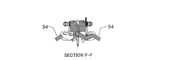
次に、図43Aから図46を参照して、外反機構105について説明する。
外反機構105は、遠隔操作により器官把持機構103を外反操作する外反操作ノブ(外反操作部)54が、フォークの長手方向を横切って回動することにより、外反軸線O3周りに器官把持機構103が回動して、器官組織を外反前位置から外反後位置に至る外反移動範囲を移動して、器官組織を外反するようになっている。Next, the
The
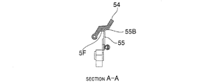
また、外反機構105は、器官把持機構103の連結プレート112とともに移動する外反位置係止部材55を備えている。
外反位置係止部材55は、連結プレート112とともに、ハウジング139と移動可能とされており、操作ノブ42が操作されると、連結プレート112とともに突刺歯部材31とすくい歯部材35の把持位置に移動されるようになっている。この場合、外反位置係止部材55及び連結プレート112は、外反位置係止部材55に形成されたガイド孔55Dと、連結プレート112に形成されたガイド孔12D(ガイド55Dと共通するものもある)が、ピン12に案内されて移動する。The
The valgus
また、操作ノブ42により、突刺歯部材31とすくい歯部材35が把持位置に移動するまでは、図43A〜図43C、図45に示すように、器官把持機構103の当接部5Fと外反前位置係止部55Bとが係合して、器官把持機構103を外反前位置に係止するようになっている。
また、図44A〜図44C、図46に示すように、器官把持機構103が外反操作された場合に、器官把持機構103の外反後位置係合部55Gと外反後位置係止部55Eとが係合して、器官把持機構103を外反後位置に係止するようになっている。Further, until the
44A to 44C and 46, when the
また、外反位置係止部材55と、連結プレート112とは、長孔12L及び係止ピン55Jにより、所定の範囲内で相対移動可能とされており、器官把持機構103が外反される場合に、外反位置係止部材55が連結プレート112と相対移動して、ハウジング139(当接部5F)が、外反位置係止部材55の係止形状部55Aの切換形状部55Cを乗り越えることにより、器官把持機構103との係合が、外反前位置係止部55Bから外反後位置係止部55Gに切り換わるようになっている。なお、切り換りが終了すると、外反位置係止部材55と連結プレート112との相対位置は、スプリング55Sにより元に戻るようになっている。
Further, the valgus
その結果、クランプ部材121R、121L、125R、125Lによれば、簡単な構成により、器官把持機構103を、外反前位置及び外反後位置において確実に保持することができる。
As a result, according to the
また、器官把持機構3の場合と同様に、クランプ部材121Rに配置された器官把持機構103とクランプ部材125Rに配置された器官把持機構103、及びクランプ部材121Lに配置された器官把持機構103とクランプ部材125Lに配置された器官把持機構103は、それぞれ把持動作同期手段145により同期して作動するようになっている。
Similarly to the
なお、第1の把持歯板部材と第2の把持歯板部材とは、把持歯駆動部が、第1の把持歯板部材と第2の把持歯板部材の少なくともいずれか一方に接続されて、互いに相対移動可能とされた構成であってもよい。 The first gripping toothplate member and the second gripping toothplate member are such that the gripping tooth drive unit is connected to at least one of the first gripping toothplate member and the second gripping toothplate member. The configuration may be such that they can move relative to each other.
また、クランプ102R、102Lは、クランプ部材121R及び125R、125R、125Lの先端側の間隔を一定に保持するための先端間隔保持部を備えている。
クランプ部材125R、125Lの器官把持機構103を構成する連結プレート112は、図47から図50に示すように、先端から後端側に向かってクランプ部材121R、121Lから離間する側に傾斜する先端傾斜部112Aが形成されている。In addition, the
As shown in FIGS. 47 to 50, the connecting
その結果、図48、図50に示すように、操作ノブ42を作動させて器官把持機構103による器官組織Pの把持を行なうことにより、先端傾斜部112Aをクランプ部材121R、121Lの連結収納部22Cに収容させて、容易かつ確実にクランプ102R、102Lのクランプ面同士間の間隔を所定間隔に形成することができるようになっている。
先端傾斜部112A及び連結収納部22Cは、先端間隔保持部を形成している。As a result, as shown in FIGS. 48 and 50, the
The tip inclined
次に、図51Aから図54Cを参照して、外反機構105の作用について、説明する。
まず、図51Aから図51Cに示すように、器官把持機構103により、器官組織Pを把持する。
このとき、外反操作ノブ54は、図51Bに示す位置にあり、把持された器官組織Pは図51Cに示すような状態である。Next, the operation of the
First, as shown in FIGS. 51A to 51C, the organ tissue P is gripped by the
At this time, the
次に、外反操作ノブ54を回動させて、器官把持機構103により器官組織Pを外反すると、図52Aから図52Cに示すように、器官組織Pの外反が開始する。図52Aから図52Cに示したのは、外反途中の状態であり、外反操作ノブ54は、図52Bに示す位置にあり、把持された器官組織Pは図52Cに示すような状態である。
Next, when the
図54Aから図54Cに示したのは、器官把持機構103を回動させることにより、器官組織Pを外反させる過程を示す図であり、図54Aは外反前の状態を、図54Bは外反途中の状態を、図54Cは外反後の状態を示している。
FIG. 54A to FIG. 54C are diagrams showing a process of inverting the organ tissue P by rotating the
次に、図55Aから図61を参照して、吻合器101に係るロック解除手段について説明する。
ロック解除手段は、図55Aから図55Cに示すように、解除ノブ129と、解除ノブ管理手段85とを備えている。射出ノブ164R、164Lは、前進させられて前進端に到達した場合に、射出部ロック部材76(先行射出部ロック手段)により拘束されるようになっている。なお、射出ノブ164R、164Lは、いずれを先行させてもよく、後から作動させた射出部164も拘束されるようになっている。Next, with reference to FIG. 55A to FIG. 61, the unlocking means according to the
As shown in FIGS. 55A to 55C, the lock release means includes a
解除ノブ129は、射出ノブ164R及び射出ノブ164Lがともに作動されて吻合操作を完了した場合に、解除ノブ管理手段85が作動することにより、解除ノブ129を操作して、上下ロック及び器官把持機構103による把持を解除するようになっている。
The
解除ノブ129は、係合凸部128とともに、クランプ102R、102Lの上下ロックを構成するとともにロックされた上下ロック27を解除するためのものであり、スプリング129Sによって先端側に付勢され、解除ノブ129を手前側に作動させることにより、上下ロックが解除されるようになっている。
The
また、解除ノブ129には、解除ノブ129の長手方向の移動を拘束するための係合凸部129Aと、ロック部材129Bを有しており、ロック部材129Bの先端には、係合凸部128に形成された係合部128Aと係合して、上側のクランプ部材121R、121Lと、下側のクランプ部材125R、125Lとが閉じられた場合に、解除ノブ129を作動して解除しなければ、上側のクランプ部材121R、121Lと、下側のクランプ部材125R、125Lとが開かないようになっている。
Further, the
係合凸部128は、下側クランプ部材125R、125Lに配置され、解除ノブ129の係合部材129Bは、上側のクランプ部材121R、121Lに配置されている。
係合凸部28は、上側のクランプ部材121R、121L側に向かって伸びる板状部材からなり、先端側に係合凸部129Bと係合するための三角形状に形成された係合部128Aが形成されている。
係合部128Aには、軸線O1R、又はO1Lと平行に形成された複数の係合溝を有している。The engagement
The engaging
The engaging
解除ノブ管理手段85は、ロック部材86と、ロック管理部材(係止部管理部材)87とを備えている。
ロック部材86は、クランプ部材102Rとクランプ102Lのそれぞれに、吻合器101の長手方向に延在し、左右対称に一対配置され、先端側から後端側に向かうにつれて左右方向外側に拡がるロック傾斜部(第2ロック係止部)86Aと、長手方向の途中に左右方向内側に凹んで形成されたロック凹部(第1ロック係止部)86Bとを備え、それぞれ先端側を中心に回動するようになっている。The release knob management means 85 includes a
The
ロック管理部材87は、射出ノブ164R、164L側に、揺動部材88を備え、図示しないガイドによって吻合器101の長手方向に移動可能とされ、揺動部材88を介して射出ノブ164R、164Lの作動を検知し、先端側に移動するようになっている。
ロック管理部材87は、管理凸部87Aを有し、左右のクランプ102R、102Lが開いている場合には、長手方向に移動自在とされ、左右のクランプ102R、102Lが閉じられた場合には、左右のロック部材86間に管理凸部87Aが挟まれるようになっている。The
The
管理凸部87Aが、左右のロック部材86間の後端側に挟まれている場合には、ロック部材86は、後端側が左右方向外側に拡げられ、先端側に挟まれている場合には、ロック部材86の後端側が左右方向内側に変位して接近可能となる。
When the management
ロック部材86の後端側が左右外側に拡がり、左右方向内側に変位不能である場合には、ロック部材86のロック傾斜部86A、及びロック凹部86Bは、左右方向外側に位置している。
ロック傾斜部86A、及びロック凹部86Bは、左右方向外側に位置していると、解除ノブ129の傾斜部129A、及び操作ノブ42のロック凸部42Aがそれぞれロック傾斜部86A、及びロック凹部86Bと係合して、解除ノブ129が長手方向において拘束されるようになっている。When the rear end side of the
When the lock inclined
なお、ロック解除手段は、図56Aから図57Bに示すように、クランプ102Rと102Lが閉じられていない場合には、左右のロック部材86間に、ロック管理部材87が挟まれることがないために、器官把持機構103、解除ノブ129の操作は自在に行なうことができ、一方、クランプ102Rと102Lが閉じられている場合には、射出ノブ164R、164Lを作動させなければ、解除ノブ129を作動させることができないようになっている。
その結果、二つの射出部の作動が完了するまで、クランプ102R、102Lによる器官組織Pの挟持、及び器官把持機構103による器官組織Pの把持を確実に維持することができる。As shown in FIGS. 56A to 57B, the lock release means is configured so that the
As a result, the clamping of the organ tissue P by the
次に、ロック解除手段の作用について説明する。
まず、図58に示すように、左右のクランプ102R、102Lを軸線O2周りに回動して閉じ、吻合器101を構成する。
左右のクランプ102R、102Lが閉じられると、左右のロック部材86の後端側に、ロック管理部材87の管理凸部87Aが挟まれる。
左右のロック部材86の後端側に管理凸部87Aが挟まれると、解除ノブ129の傾斜部129A、操作ノブ42のロック凸部42Aが、それぞれロック部材86のロック傾斜部86A、ロック凹部86Bと係合して解除ノブ129が拘束される。Next, the operation of the unlocking means will be described.
First, as shown in FIG. 58, the left and
When the left and
When the management
次に、図59に示すように、例えば、右側の射出ノブ164Rを作動させて前進端まで移動させると、射出ノブ164Rが射出部ロック部材76により前進端で拘束される。このとき、揺動部材88は、図59における反時計方向に回動するので、射出ノブ164Rの移動をロック管理部材87に伝えるのが防止される。
Next, as shown in FIG. 59, for example, when the
次に、図60に示すように、左側の射出ノブ164Lを作動させて前進端まで移動させると、射出ノブ164Lが射出部ロック部材76により前進端で拘束される。このとき、揺動部材88は、図60における時計方向に回動するとともに、射出ノブ164Lの移動がロック管理部材87に伝達される。
射出ノブ164Lの移動がロック管理部材87に伝達されると、ロック管理部材87の管理凸部87Aが、左右のロック部材86間を後端側から前端側に移動して左右のロック部材86が左右方向内側に変位可能となり、解除ノブ129を手前側に移動させることが可能となる。Next, as shown in FIG. 60, when the
When the movement of the
次に、図61に示すように、解除ノブ129を手前側に移動させると、解除ノブ129の傾斜部129Aにより、ロック部材86のロック傾斜部86Aが左右方向内側に変位して、操作ノブ42のロック凸部42Aとロック凹部86Bと係合が解除されるとともに、操作ノブ42が手前側に移動されて、器官把持機構103により器官組織Pの把持が解除される。
Next, as shown in FIG. 61, when the
解除ノブ管理手段85によれば、上下ロック及び器官把持機構103による把持を、解除ノブ129の簡単な操作によって、一括して解除することができる。
その結果、吻合を安全に行なうことができる。According to the release knob management means 85, the vertical lock and the gripping by the
As a result, the anastomosis can be performed safely.
クランプ部材121R、121L、125R、125Lの外反機構105によれば、把持した器官組織Pへの引張力及び器官組織Pの伸びを抑制しつつスムースに器官組織Pを外反することができ、器官組織Pに無理な力が加わることが抑制されて器官組織Pへの負担を軽減することができる。
According to the
クランプ102R,102Lによれば、クランプ102によりクランプした器官組織Pをほぼ同一の厚さに維持することができるので器官組織Pを安定して把持するとともに縫合することができる。
According to the
また、吻合器101によれば、先行射出部ロック手段、射出部解除機構を有しているので、吻合操作が完了するまで、器官把持機構103、外反機構105等を安定して保持することができる。
吻合器101によれば、ロック解除手段を有しているので、器官把持機構103が器官組織Pを把持した状態で吻合器101が開くことが抑制され、器官組織Pの損傷を抑制することができる。
以上のように、吻合器1によれば、吻合手術を容易かつ効率的に行なうことができ、その結果、吻合に際しての器官組織Pへの損傷を抑制することができる。Further, since the
According to the
As described above, according to the
なお、本発明は上記した実施の形態に限定されるものではなく、その趣旨を逸脱しない範囲で適宜変更可能であり、上記実施形態において記載した構成の一部を除いた構成としてもよい。 Note that the present invention is not limited to the above-described embodiment, and can be modified as appropriate without departing from the spirit of the present invention, and may have a configuration excluding a part of the configuration described in the above-described embodiment.
また、器官把持機構3、103における突刺歯32及びすくい歯36の露出を、操作ノブ41、42を手前側から先端側に移動して行なう場合について説明したが、操作ノブ41、42を先端側から手前側に移動することで突刺歯32及びすくい歯36が露出する構成、すなわち吻合器1の先端側を一方側、手前側を他方側とする構成としてもよい。また、第1の駆動機構及び第2の駆動機構を共通の操作ノブ41、42により操作するかどうかは任意に設定可能な事項である。
Further, the case where the piercing
また、上記実施の形態においては、対向する2つのクランプ2R、2Lが、軸線O2周りに回動し、クランプ2R、2Lを構成する一対のクランプ部材20R、20Lが、それぞれ軸線O1R、O1L周りに回動可能に構成されている場合について説明したが、例えば、これら2つのクランプ2R、2Lを構成するクランプ部材121R、25R、21L、25Lのうち、いずれか一つ又は複数が、軸線O1R、O1L(O1)、O2周りの回動に代えて、ガイド等により、離間、接近するように構成されてもよい。
In the above-described embodiment, the two opposing
また、上記第1、第2の実施形態においては、第1の駆動機構による突刺歯32及びすくい歯36の露出を、突刺歯部材31及びすくい歯部材35をハウジング39、139に対して吻合器1の長手方向に移動し、第2の駆動機構による突刺歯32とすくい歯36の位相変化をすくい歯部材35を、突刺歯部材31及びハウジング39、139に対して吻合器1の長手方向に移動する場合について説明したが、突刺歯部材31、すくい歯部材35、ハウジング39、139のうちいずれの部材を移動させることによりこれらを相対移動させるかは任意に設定可能な事項である。
In the first and second embodiments, the piercing
また、上記実施の形態においては、第1の駆動機構及び第2の駆動機構を操作ノブ41、42により作動させる場合について説明したが、第1の駆動機構及び第2の駆動機構を個別に作動させる構成としてもよい。 In the above embodiment, the case where the first drive mechanism and the second drive mechanism are operated by the operation knobs 41 and 42 has been described. However, the first drive mechanism and the second drive mechanism are individually operated. A configuration may be adopted.
また、第1の駆動機構と第2の駆動機構が、操作ノブ41の移動を突刺歯部材31及びすくい歯部材35に形成された第1、第2係合切欠部33、37により突刺歯32及びすくい歯36の変位に変換する場合について説明したが、突刺歯32及びすくい歯36の変位を他の機構により付与するようにしてもよい。また、操作ノブ41の移動を突刺歯32及びすくい歯36の変位に変換するのではなく、例えば、モータ、アクチュエータ等により突刺歯32及びすくい歯36に変位を与える構成してもよい。
Further, the first drive mechanism and the second drive mechanism cause the movement of the
また、例えば、外反操作ノブ51、54を吻合器1、101の長手方向に移動させることにより第1の駆動機構、第2の駆動機構を駆動する構成としてもよい。
In addition, for example, the first drive mechanism and the second drive mechanism may be driven by moving the valgus operation knobs 51 and 54 in the longitudinal direction of the
なお、上記第1の実施形態においては、外反機構105が4つ以上のリンクを用いて構成される場合について説明したが、例えば、3つ以下のリンク機構により構成してもよいし、また、連結ロッド12周りに器官把持機構103を回動する構成としてもよい。
In the first embodiment, the case where the
また、上記第2の実施形態においては、クランプ2Rのクランプ部材121Rに配置された外反機構105の外反軸O3Uと、クランプ部材125Rに配置された外反機構105の外反軸O3Dが、クランプ部材121Rとクランプ部材125Rを閉じた場合に、外反軸O3上に同軸に配置される場合について説明したが、クランプ部材121Rとクランプ部材125Rを閉じた状態で、クランプ部材121Rの外反軸O3Uと、クランプ部材125Rの外反軸O3Dが、別々の軸線上に配置されるようにしてもよい。
In the second embodiment, the valgus shaft O3U of the
なお、上記実施の形態においては、吻合器1、吻合器101に関して、クランプ部材21R、121R及びクランプ部材25L、125Lにファイアリング機構60、160が配置され、クランプ部材21L、121L及びクランプ部材25R、125Rにアンビル部材67が配置される場合について説明したが、クランプ部材21L、121L及びクランプ部材25R、125Rにファイアリング機構60、160を配置し、クランプ部材21R、121R及びクランプ部材25L、125Lにアンビル部材67を配置してもよい。
In the above embodiment, regarding the
また、縫合機構に係るフローティング機構を、設けるかどうかは任意に設定することができる。
また、ファイアリング機構60、160と、アンビル部材67のいずれをフローティングさせるかについても、任意に設定可能な事項である。Whether or not to provide a floating mechanism related to the suturing mechanism can be arbitrarily set.
In addition, which of the firing
また、上記第1の実施形態においては、射出スライダ63Rが先に前進し、後から射出スライダ63Lが前進する場合について説明したが、射出部62の操作順序を上記実施形態と逆とする構成としてもよい。
In the first embodiment, the case where the
また、吻合器1においては、外反機構5がマルチリンクにより構成され、吻合器101では、外反機構105が、シングルヒンジにより構成される場合について説明したが、例えば、フォークを横切る方向にスライドするような構成の外反機構を用いることも可能である。
In the
また、上記実施の形態においては、吻合器1が、射出順序管理手段、先行射出部ロック手段、射出部ロック解除手段、把持解除機構を備える場合について説明したが、これらを備えるかどうかは任意に選択可能である。
In the above embodiment, the case where the
また、上記実施の形態においては、クランプ2R、2L、102R、102L、及びこれに対応するクランプ部材を、吻合器1、101に用いる場合について説明したが、腸管、胃等に筒状の器管の他、器官組織を縫合する他の縫合器に適用してもよいし、器官組織を把持する他の手術用具に適用してもよい。
また、人の器官組織に限定されることなく、家畜やペット等の動物を対象とする生体の把持装置、縫合器、吻合器に適用できることはいうまでもない。In the above embodiment, the clamps 2R, 2L, 102R, and 102L and the corresponding clamp members are used for the
Needless to say, the present invention is not limited to human tissue, and can be applied to living body grasping devices, suture devices, and anastomosis devices for animals such as livestock and pets.
また、上記第1の実施の形態においては、外観カバーが軽量なプラスチックにより形成される場合について、上記第2の実施の形態においては、外観カバーにより被覆していない場合について説明したが、外観カバーにより被覆するかどうか、また、被覆する場合に外観カバーとして用いる材料としては、生体における拒絶反応を考慮したチタン等をはじめとする金属材料、その他の材料によって形成することも可能である。 Further, in the first embodiment, the case where the outer cover is formed of a lightweight plastic has been described. In the second embodiment, the case where the outer cover is not covered with the outer cover has been described. As a material used as an exterior cover in the case of coating, it is also possible to form a metal material such as titanium in consideration of rejection in the living body, or other materials.
この発明に係る吻合器によれば、器官組織の吻合を効率的かつ安定して行なうことができるので、産業上利用可能である。 The anastomosis instrument according to the present invention can be used industrially because an anastomosis of organ tissues can be performed efficiently and stably.
P 器官組織
O1 軸線
O2 軸線
S ステープル
1 吻合器
2R、2L クランプ
3 器官把持機構
5 外反手段
13 UBコネクタ
13A 係止凹部
20R、20L 一対のクランプ部材
21、25 クランプ部材対
21R、25R、21L、25L クランプ部材
31 突刺歯部材
32 突刺歯
32A 先端部
33 第1係合切欠部
33A 第1傾斜切欠部
33B 逃部
35 すくい歯部材
36 すくい歯
37 第2係合切欠部
39 ハウジング
39B カットプロテクタ
39E 縁部
41 操作ノブ
42 操作ノブ
43 係合ピン(第1係合部材、第2係合部材)
45 把持動作同期手段
45A 同期凸部(把持動作同期手段)
45B 同期凹部(把持動作同期手段)
51 外反操作ノブ
51A ノブ係止凸部
53、53A、53B、53C、53D リンク
54 外反操作ノブ
J1、J2、J3、J4 支点
60 ファイアリング機構
61 ステープル収納部
61A 位置決ピン(位置決手段)
62 射出部
63、63R、63L 射出スライダ
64S スライダガイド
64T スライダガイド
66A 位置決孔(位置決手段)
67 アンビル部材
67A アンビル取付穴(フローティング機構)
67B 取付ネジ(フローティング機構)
68 フローティング機構
71 スライダロック部材
71A ロック部
71B 解除ピン
75 スライダロック用凹部
76 射出部ロック部材(先行射出部ロック手段)
80 解除溝部
90 リリース部材
93 係合ピン
95 リリース部材制御部
96 リリース部材変形傾斜部
97 リリース部材復元段差部
98 傾斜部
101 吻合器
102R、102L クランプ
103 器官把持機構
105 外反手段
112 連結プレート
112A 先端傾斜部
120R、120L 一対のクランプ部材
121、125 クランプ部材対
121R、125R、121L、125L クランプ部材
129 解除ノブ
145 把持動作同期手段
160 ファイアリング機構P organ tissue O1 axis O2
45 Grasping movement synchronization means 45A Synchronous convex part (gripping movement synchronization means)
45B Synchronous recess (gripping operation synchronization means)
51
62
67
67B Mounting screw (floating mechanism)
68 Floating
80
Claims (16)
前記フォークの長手方向に複数の突刺歯が等ピッチで配列された第1の把持歯板部材と、
前記第1の把持歯板部材に沿って配置されるとともに各突刺歯と対応し前記対応する突刺歯と等ピッチに配置されかつ先端側を前記対応する突刺歯側に向けて形成される複数のすくい歯を有し、前記第1の把持歯板部材と相対移動することにより前記すくい歯の先端部が前記突刺歯の先端部と合致するように構成された第2の把持歯板部材と、
前記第1の把持歯板部材と第2の把持歯板部材とを互いに相対移動可能に収納するハウジングと、
前記第1の把持歯板部材と前記第2の把持歯板部材の少なくともいずれか一方に接続され、前記第1の把持歯板部材と前記第2の把持歯板部材とを長手方向に1ピッチ分相対移動させる把持歯駆動部と、
を有し、前記器官組織の縫合部近傍を把持するように構成された器官把持機構と、
前記器官把持機構と接続され、前記器官把持機構を、前記フォークの長手方向を横切って、前記突刺歯が前記器官組織の縫合部近傍を突刺す外反前位置から前記器官組織の縫合部が縫合面に位置する外反後位置に至る外反移動範囲を移動させるように構成された外反機構と、
前記フォークに配置され、前記器官把持機構の外反移動範囲を規定するとともに、前記器官把持機構を前記外反前位置と前記外反後位置のそれぞれにおいて保持し、前記器官把持機構が前記外反後位置側に移動した場合における前記第1の把持歯板部材と第2の把持歯板部材とを管理するための把持管理手段を備えることを特徴とするクランプ部材。 A fork that has a clamping surface that sandwiches an organ tissue and a suture surface that sutures an organ wall, and extends in the suture direction.
A first grasping tooth plate member in which a plurality of piercing teeth are arranged at an equal pitch in the longitudinal direction of the fork;
A plurality of pins arranged along the first gripping tooth plate member, corresponding to each piercing tooth, arranged at the same pitch as the corresponding piercing tooth, and formed with the tip side facing the corresponding piercing tooth side. A second grasping toothplate member having scoop teeth and configured to move relative to the first grasping toothplate member so that a tip portion of the scoop teeth matches a tip portion of the piercing tooth;
A housing for housing the first gripping toothplate member and the second gripping toothplate member so as to be movable relative to each other;
It is connected to at least one of the first gripping toothplate member and the second gripping toothplate member, and the first gripping toothplate member and the second gripping toothplate member are spaced by one pitch in the longitudinal direction. A gripping tooth drive for relative movement, and
An organ gripping mechanism configured to grip the vicinity of the sutured portion of the organ tissue,
The organ grasping mechanism is connected to the organ grasping mechanism, and the suture portion of the organ tissue is sutured from a position before valgus where the piercing teeth pierce the vicinity of the suture portion of the organ tissue across the longitudinal direction of the fork. A valgus mechanism configured to move a valgus movement range that reaches the posterior valgus position located on the surface;
The organ gripping mechanism is disposed on the fork to define a valgus movement range of the organ gripping mechanism, and holds the organ gripping mechanism at each of the front valgus position and the post valgus position, and the organ gripping mechanism is A clamp member comprising grip management means for managing the first grip tooth plate member and the second grip tooth plate member when moved to the rear position side.
前記器官把持機構は、
第1の把持歯板部材と第2の把持歯板部材とが相対移動して前記器官組織を把持する場合に、前記突刺歯が突刺し方向に前進するように構成されており、
前記突刺歯が前記突刺し方向の後退位置にある場合に、前記突刺歯及び前記すくい歯の先端部を格納して、前記突刺歯及び前記すくい歯の先端部が外部と接触するのを抑制する把持歯保護壁部を備えることを特徴とするクランプ部材。 The clamp member according to claim 1,
The organ gripping mechanism is
When the first grasping tooth plate member and the second grasping tooth plate member relatively move to grasp the organ tissue, the piercing tooth is configured to advance in the piercing direction,
When the piercing teeth are in the retracted position in the piercing direction, the piercing teeth and the tip portions of the rake teeth are stored to prevent the piercing teeth and the tip portions of the rake teeth from coming into contact with the outside. A clamp member comprising a gripping tooth protection wall.
前記突刺歯は、
前記突刺し方向に延在し又は前記すくい歯側に傾く方向に延在して形成されていることを特徴とするクランプ部材。 The clamp member according to claim 1 or 2,
The piercing tooth is
A clamp member characterized by extending in the piercing direction or extending in a direction inclined toward the rake teeth side.
前記突刺歯は、
先端部側が前記すくい歯側に漸次変位するように形成されていることを特徴とするクランプ部材。 The clamp member according to claim 1 or 2,
The piercing tooth is
A clamp member, wherein the tip end side is formed so as to be gradually displaced toward the rake tooth side.
前記器官把持機構は、
前記第1の把持歯板部材には、前記器官組織を把持する場合に、前記第2の把持歯板部材が前記第1の把持歯板部材に対して相対移動する把持動作方向に向かって、前記突刺歯から離間する側に傾斜する第1傾斜切欠部と、前記第1傾斜切欠部の前記把持動作方向端部から前記把持動作方向に伸びる逃部とを有する第1係合切欠部が形成され、
前記第2の把持歯板部材には、把持歯動作方向に向かって前記すくい歯から離間する側に傾斜する第2係合切欠部が形成され、
前記把持歯駆動部には、前記第1の係合切欠部及び前記第2係合切欠部と係合する把持歯動作部材が形成され、
前記把持歯動作部材が前記把持動作方向に移動されることにより、前記すくい歯及び前記突刺歯の先端部が前記突刺し方向に前進するとともに、前記すくい歯が前記対応する突刺歯に向かって移動するように構成されていることを特徴とするクランプ部材。 The clamp member according to any one of claims 1 to 4,
The organ gripping mechanism is
In the first grasping tooth plate member, when grasping the organ tissue, the second grasping tooth plate member moves relative to the first grasping tooth plate member toward the grasping operation direction. A first engagement notch portion having a first inclined notch portion that is inclined to the side away from the piercing tooth and a relief portion that extends from the end portion of the first inclined notch portion in the gripping operation direction is formed. And
The second gripping tooth plate member is formed with a second engagement notch portion inclined toward the side away from the rake teeth toward the gripping tooth operation direction ,
The gripping tooth drive member is formed with a gripping tooth operating member that engages with the first engagement notch and the second engagement notch,
When the gripping tooth movement member is moved in the gripping movement direction, the rake teeth and the tip portions of the piercing teeth advance in the piercing direction, and the rake teeth move toward the corresponding piercing teeth. It is comprised so that it may carry out. The clamp member characterized by the above-mentioned.
前記器官把持機構は、
前記ハウジングの前記縫合面側にガイドが形成され、前記ガイドに沿って切刃を移動させることにより、
前記クランプ面に配置された前記器官組織を、前記縫合部又は前記縫合部に対応する位置から所定間隔をあけて切離可能とすることを特徴とするクランプ部材。 The clamp member according to any one of claims 1 to 5,
The organ gripping mechanism is
A guide is formed on the suture surface side of the housing, and by moving a cutting blade along the guide,
A clamp member characterized in that the organ tissue disposed on the clamp surface can be separated from the suture part or a position corresponding to the suture part at a predetermined interval.
前記外反機構は、
それぞれの前記フォークに配置されるとともにそれぞれの前記器官把持機構に連結され、回動、スライド、または複合した動作をすることにより、前記突刺歯及び前記すくい歯の先端部が前記外反移動範囲と対応する所定の外反軌跡を通過させるための外反操作部を備えることを特徴とするクランプ部材。 The clamp member according to any one of claims 1 to 6,
The valgus mechanism is
It is arranged on each fork and connected to each organ gripping mechanism, and by rotating, sliding, or performing a combined operation, the tip of the piercing tooth and the rake tooth is set to the valgus movement range. A clamp member comprising a valgus operating portion for passing a corresponding predetermined valgus locus.
前記外反機構は、
前記外反操作部により前記器官把持機構を遠隔操作で外反可能とされ、かつ前記外反前位置、前記外反後位置において、前記器官把持機構を保持可能に構成されることを特徴とするクランプ部材。 The clamp member according to claim 7 ,
The valgus mechanism is
The organ gripping mechanism is configured to be valgusable remotely by the valgus operation unit, and is configured to be able to hold the organ gripping mechanism at the position before valgus and the position after valgus. Clamp member.
前記外反機構は、
少なくとも4つのリンクからなるリンク機構を備え、前記縫合方向と直交する面において前記リンク機構が姿勢を変えることにより、前記突刺歯及び前記すくい歯の先端部が前記外反移動範囲と対応する所定の外反軌跡を移動するように構成されていることを特徴とするクランプ部材。 The clamp member according to any one of claims 1 to 8,
The valgus mechanism is
A link mechanism comprising at least four links, and the link mechanism changes its posture in a plane orthogonal to the stitching direction, whereby the tip portions of the piercing teeth and the rake teeth correspond to the valgus movement range; A clamp member characterized by being configured to move along a hallux trajectory.
前記器官把持機構は、
把持駆動部と、前記第1の把持歯板部材及び前記第2の把持歯板部材とは、
前記フォークの長手方向を横切る方向に相対移動可能に接続されていることを特徴とするクランプ部材。 The clamp member according to claim 9,
The organ gripping mechanism is
The gripping drive unit, the first gripping toothplate member, and the second gripping toothplate member are:
A clamp member characterized by being connected so as to be relatively movable in a direction transverse to the longitudinal direction of the fork.
前記外反機構は、
前記縫合方向に沿って形成される外反軸線周りに回動することで、前記突刺歯及び前記すくい歯の先端部が、前記外反移動範囲と対応する所定の外反軌跡を移動するように前記器官把持機構を支持する外反回動支持部を備えることを特徴とするクランプ部材。 The clamp member according to any one of claims 1 to 8,
The valgus mechanism is
By rotating around the valgus axis formed along the stitching direction, the tip portions of the piercing teeth and the rake teeth move along a predetermined valgus locus corresponding to the valgus movement range. A clamp member comprising a valgus rotation support portion for supporting the organ gripping mechanism.
前記外反機構は、
前記外反前位置と前記外反後位置のうちいずれか一方において、選択的に前記器官把持機構を係止する外反位置係止部材を備え、
前記外反位置係止部材は、
前記把持歯駆動部が前記突刺歯と前記すくい歯とを把持位置に移動するまで、前記器官把持機構を、前記外反前位置において係止し、
前記突刺歯と前記すくい歯とが把持位置にある場合は、前記器官把持機構を外反可能とし、
外反操作が行われた後は、前記器官把持機構を、前記外反後位置において係止するように構成されていることを特徴とするクランプ部材。 The clamp member according to claim 11,
The valgus mechanism is
A valgus position locking member that selectively locks the organ gripping mechanism at any one of the position before the valgus and the position after the valgus,
The valgus position locking member is:
Until the gripping tooth drive unit moves the piercing teeth and the rake teeth to a gripping position, the organ gripping mechanism is locked at the valgus front position,
When the piercing teeth and the rake teeth are in the gripping position, the organ gripping mechanism can be valgus,
A clamp member configured to lock the organ gripping mechanism at the post-valgus position after a valgus operation is performed.
前記外反位置係止部材は、
前記器官把持機構とともに移動可能とされ、
前記突刺歯と前記すくい歯とが把持位置に移動するまで、前記器官把持機構を前記外反前位置において係止する外反前位置係止部と、
前記器官把持機構が外反操作された後に、前記器官把持機構を前記外反後位置において係止する外反後位置係止部と、を備え、
前記突刺歯と前記すくい歯とが前記把持位置にある場合には、外反操作が可能とされ、
前記外反操作されることにより前記器官把持機構と相対移動されて、前記器官把持機構との係止が、前記外反前位置係止部から前記外反後位置係止部に切り換わるように構成されていることを特徴とするクランプ部材。 The clamp member according to claim 12,
The valgus position locking member is:
Movable with the organ gripping mechanism;
A valgus front position locking portion that locks the organ gripping mechanism at the valgus front position until the piercing teeth and the rake teeth move to a gripping position;
A valgus rear position locking portion for locking the organ gripping mechanism in the posterior valgus position after the organ gripping mechanism is valgus operated;
When the piercing teeth and the rake teeth are in the gripping position, a valgus operation is possible,
When the valgus is operated, it is moved relative to the organ gripping mechanism so that the locking with the organ gripping mechanism is switched from the valgus front position locking portion to the valgus rear position locking portion. It is comprised, The clamp member characterized by the above-mentioned.
それぞれの前記クランプ部材に配置される器官把持機構を、同期して相対移動させる把持動作同期手段を備えることを特徴とするクランプ。 The clamp according to claim 14, wherein
A clamp comprising: a grasping operation synchronizing means for relatively moving an organ grasping mechanism disposed on each of the clamp members synchronously.
互いの前記縫合面を離間、接近可能とし、かつ接近した場合に前記縫合面にて対向するように二つを一組として配置し、
前記二つを一組として配置したクランプにおいて、前記縫合面にて互いに対向する二つのクランプ部材を一対として構成される二対のクランプ部材対のそれぞれには、いずれか一方のクランプ部材に配置され、前記縫合面側にステープルが通過する溝穴が形成されるとともに前記ステープルを収納するステープル収納部と、前記ステープル収納部から前記ステープルを押し出す射出部と、
前記クランプ部材対の他方のクランプ部材に配置され、前記縫合面側に前記ステープルを成形するための形状部が形成されたアンビル部材と、
を有する縫合機構が形成されることを特徴とする吻合器。 The clamp according to claim 14 or 15,
The two stitching surfaces are spaced apart, accessible, and arranged as a pair so as to face each other at the stitching surface when approached,
In the clamp in which the two are disposed as a set, each of the two pairs of clamp members configured as a pair of two clamp members facing each other on the stitching surface is disposed on one of the clamp members. A stapling portion in which a staple passes and is formed on the stitching surface side, and a staple storage portion that stores the staple, and an ejection portion that pushes out the staple from the staple storage portion,
An anvil member disposed on the other clamp member of the pair of clamp members and having a shape portion for forming the staple on the stitching surface side;
An anastomosis device characterized in that a suturing mechanism is formed.
Priority Applications (1)
| Application Number | Priority Date | Filing Date | Title |
|---|---|---|---|
| JP2010543928A JP5554722B2 (en) | 2008-12-25 | 2009-12-25 | Clamp member, clamp and anastomosis device |
Applications Claiming Priority (6)
| Application Number | Priority Date | Filing Date | Title |
|---|---|---|---|
| JP2008329866 | 2008-12-25 | ||
| JP2008329867 | 2008-12-25 | ||
| JP2008329866 | 2008-12-25 | ||
| JP2008329867 | 2008-12-25 | ||
| JP2010543928A JP5554722B2 (en) | 2008-12-25 | 2009-12-25 | Clamp member, clamp and anastomosis device |
| PCT/JP2009/007321 WO2010073734A1 (en) | 2008-12-25 | 2009-12-25 | Clamping member, clamp, and anastomotic apparatus |
Publications (2)
| Publication Number | Publication Date |
|---|---|
| JPWO2010073734A1 JPWO2010073734A1 (en) | 2012-06-14 |
| JP5554722B2 true JP5554722B2 (en) | 2014-07-23 |
Family
ID=42287366
Family Applications (2)
| Application Number | Title | Priority Date | Filing Date |
|---|---|---|---|
| JP2010543928A Expired - Fee Related JP5554722B2 (en) | 2008-12-25 | 2009-12-25 | Clamp member, clamp and anastomosis device |
| JP2010543927A Pending JPWO2010073733A1 (en) | 2008-12-25 | 2009-12-25 | Anastomosis |
Family Applications After (1)
| Application Number | Title | Priority Date | Filing Date |
|---|---|---|---|
| JP2010543927A Pending JPWO2010073733A1 (en) | 2008-12-25 | 2009-12-25 | Anastomosis |
Country Status (5)
| Country | Link |
|---|---|
| US (1) | US8523041B2 (en) |
| EP (1) | EP2371301A1 (en) |
| JP (2) | JP5554722B2 (en) |
| CN (1) | CN102202586A (en) |
| WO (2) | WO2010073733A1 (en) |
Families Citing this family (188)
| Publication number | Priority date | Publication date | Assignee | Title |
|---|---|---|---|---|
| US5865361A (en) | 1997-09-23 | 1999-02-02 | United States Surgical Corporation | Surgical stapling apparatus |
| US8584921B2 (en) | 2006-10-06 | 2013-11-19 | Covidien Lp | Surgical instrument with articulating tool assembly |
| US8061576B2 (en) | 2007-08-31 | 2011-11-22 | Tyco Healthcare Group Lp | Surgical instrument |
| US7988028B2 (en) | 2008-09-23 | 2011-08-02 | Tyco Healthcare Group Lp | Surgical instrument having an asymmetric dynamic clamping member |
| US8628544B2 (en) | 2008-09-23 | 2014-01-14 | Covidien Lp | Knife bar for surgical instrument |
| US7896214B2 (en) | 2008-09-23 | 2011-03-01 | Tyco Healthcare Group Lp | Tissue stop for surgical instrument |
| JP5554722B2 (en) * | 2008-12-25 | 2014-07-23 | 泉工医科工業株式会社 | Clamp member, clamp and anastomosis device |
| US8292154B2 (en) | 2009-04-16 | 2012-10-23 | Tyco Healthcare Group Lp | Surgical apparatus for applying tissue fasteners |
| US8899461B2 (en) | 2010-10-01 | 2014-12-02 | Covidien Lp | Tissue stop for surgical instrument |
| US9451959B2 (en) | 2011-06-09 | 2016-09-27 | Covidien Lp | Surgical fastener applying apparatus |
| US9271728B2 (en) | 2011-06-09 | 2016-03-01 | Covidien Lp | Surgical fastener applying apparatus |
| US9289209B2 (en) | 2011-06-09 | 2016-03-22 | Covidien Lp | Surgical fastener applying apparatus |
| US8763876B2 (en) | 2011-06-30 | 2014-07-01 | Covidien Lp | Surgical instrument and cartridge for use therewith |
| US20130012958A1 (en) | 2011-07-08 | 2013-01-10 | Stanislaw Marczyk | Surgical Device with Articulation and Wrist Rotation |
| US9539007B2 (en) | 2011-08-08 | 2017-01-10 | Covidien Lp | Surgical fastener applying aparatus |
| US9155537B2 (en) | 2011-08-08 | 2015-10-13 | Covidien Lp | Surgical fastener applying apparatus |
| US9724095B2 (en) | 2011-08-08 | 2017-08-08 | Covidien Lp | Surgical fastener applying apparatus |
| US9016539B2 (en) | 2011-10-25 | 2015-04-28 | Covidien Lp | Multi-use loading unit |
| US8740036B2 (en) | 2011-12-01 | 2014-06-03 | Covidien Lp | Surgical instrument with actuator spring arm |
| US10299815B2 (en) | 2012-01-19 | 2019-05-28 | Covidien Lp | Surgical instrument with clam releases mechanism |
| US8864010B2 (en) | 2012-01-20 | 2014-10-21 | Covidien Lp | Curved guide member for articulating instruments |
| US8979827B2 (en) | 2012-03-14 | 2015-03-17 | Covidien Lp | Surgical instrument with articulation mechanism |
| US9526497B2 (en) | 2012-05-07 | 2016-12-27 | Covidien Lp | Surgical instrument with articulation mechanism |
| US9232944B2 (en) | 2012-06-29 | 2016-01-12 | Covidien Lp | Surgical instrument and bushing |
| US9364217B2 (en) | 2012-10-16 | 2016-06-14 | Covidien Lp | In-situ loaded stapler |
| US9345480B2 (en) | 2013-01-18 | 2016-05-24 | Covidien Lp | Surgical instrument and cartridge members for use therewith |
| US10561432B2 (en) | 2013-03-05 | 2020-02-18 | Covidien Lp | Pivoting screw for use with a pair of jaw members of a surgical instrument |
| US9629628B2 (en) | 2013-03-13 | 2017-04-25 | Covidien Lp | Surgical stapling apparatus |
| US9814463B2 (en) | 2013-03-13 | 2017-11-14 | Covidien Lp | Surgical stapling apparatus |
| US9717498B2 (en) | 2013-03-13 | 2017-08-01 | Covidien Lp | Surgical stapling apparatus |
| US9668728B2 (en) | 2013-03-13 | 2017-06-06 | Covidien Lp | Surgical stapling apparatus |
| US9510827B2 (en) | 2013-03-25 | 2016-12-06 | Covidien Lp | Micro surgical instrument and loading unit for use therewith |
| CN103263283B (en) * | 2013-05-02 | 2015-10-21 | 苏州天臣国际医疗科技有限公司 | Linear cutting anastomat |
| US9445810B2 (en) | 2013-06-12 | 2016-09-20 | Covidien Lp | Stapling device with grasping jaw mechanism |
| US9662108B2 (en) | 2013-08-30 | 2017-05-30 | Covidien Lp | Surgical stapling apparatus |
| CN105682567B (en) | 2013-11-04 | 2021-09-10 | 柯惠Lp公司 | Surgical fastener applying apparatus |
| AU2013403917A1 (en) | 2013-11-04 | 2016-04-28 | Covidien Lp | Surgical fastener applying apparatus |
| AU2013403915A1 (en) | 2013-11-04 | 2016-04-28 | Covidien Lp | Surgical fastener applying apparatus |
| CA2932285C (en) | 2013-12-17 | 2019-10-08 | Standard Bariatrics, Inc. | Resection line guide for a medical procedure and method of using same |
| US9867613B2 (en) | 2013-12-19 | 2018-01-16 | Covidien Lp | Surgical staples and end effectors for deploying the same |
| US9848874B2 (en) | 2014-02-14 | 2017-12-26 | Covidien Lp | Small diameter endoscopic stapler |
| CA2944383C (en) | 2014-03-29 | 2019-09-17 | Standard Bariatrics, Inc. | End effectors, surgical stapling devices, and methods of using same |
| EP3125796B1 (en) | 2014-03-29 | 2024-03-06 | Standard Bariatrics Inc. | Surgical stapling devices |
| US9757126B2 (en) | 2014-03-31 | 2017-09-12 | Covidien Lp | Surgical stapling apparatus with firing lockout mechanism |
| US9668733B2 (en) | 2014-04-21 | 2017-06-06 | Covidien Lp | Stapling device with features to prevent inadvertent firing of staples |
| US9861366B2 (en) | 2014-05-06 | 2018-01-09 | Covidien Lp | Ejecting assembly for a surgical stapler |
| WO2015174985A1 (en) | 2014-05-15 | 2015-11-19 | Lp Covidien | Surgical fastener applying apparatus |
| CN104083190B (en) * | 2014-06-18 | 2018-05-25 | 北京航空航天大学 | A kind of medical operating instrument is engaged position surface texture |
| CN105395230B (en) * | 2014-09-11 | 2017-05-10 | 天津瑞贝精密机械技术研发有限公司 | Outwards-turned type end-end surgical stapler |
| US10039545B2 (en) | 2015-02-23 | 2018-08-07 | Covidien Lp | Double fire stapling |
| US10130367B2 (en) | 2015-02-26 | 2018-11-20 | Covidien Lp | Surgical apparatus |
| US10085749B2 (en) | 2015-02-26 | 2018-10-02 | Covidien Lp | Surgical apparatus with conductor strain relief |
| US9918717B2 (en) | 2015-03-18 | 2018-03-20 | Covidien Lp | Pivot mechanism for surgical device |
| US10463368B2 (en) | 2015-04-10 | 2019-11-05 | Covidien Lp | Endoscopic stapler |
| US10299789B2 (en) | 2015-05-05 | 2019-05-28 | Covidie LP | Adapter assembly for surgical stapling devices |
| US10117650B2 (en) | 2015-05-05 | 2018-11-06 | Covidien Lp | Adapter assembly and loading units for surgical stapling devices |
| US10039532B2 (en) | 2015-05-06 | 2018-08-07 | Covidien Lp | Surgical instrument with articulation assembly |
| US10143474B2 (en) | 2015-05-08 | 2018-12-04 | Just Right Surgical, Llc | Surgical stapler |
| US10349941B2 (en) | 2015-05-27 | 2019-07-16 | Covidien Lp | Multi-fire lead screw stapling device |
| US10172615B2 (en) | 2015-05-27 | 2019-01-08 | Covidien Lp | Multi-fire push rod stapling device |
| US10548599B2 (en) | 2015-07-20 | 2020-02-04 | Covidien Lp | Endoscopic stapler and staple |
| US9987012B2 (en) | 2015-07-21 | 2018-06-05 | Covidien Lp | Small diameter cartridge design for a surgical stapling instrument |
| US10064622B2 (en) | 2015-07-29 | 2018-09-04 | Covidien Lp | Surgical stapling loading unit with stroke counter and lockout |
| US10045782B2 (en) | 2015-07-30 | 2018-08-14 | Covidien Lp | Surgical stapling loading unit with stroke counter and lockout |
| WO2017040884A1 (en) * | 2015-09-04 | 2017-03-09 | The Regents Of The University Of Michigan | Device to aid in arterial microvascular anastomosis |
| US10285837B1 (en) | 2015-09-16 | 2019-05-14 | Standard Bariatrics, Inc. | Systems and methods for measuring volume of potential sleeve in a sleeve gastrectomy |
| US10213204B2 (en) | 2015-10-02 | 2019-02-26 | Covidien Lp | Micro surgical instrument and loading unit for use therewith |
| US10772632B2 (en) | 2015-10-28 | 2020-09-15 | Covidien Lp | Surgical stapling device with triple leg staples |
| US10595864B2 (en) | 2015-11-24 | 2020-03-24 | Covidien Lp | Adapter assembly for interconnecting electromechanical surgical devices and surgical loading units, and surgical systems thereof |
| US10111660B2 (en) | 2015-12-03 | 2018-10-30 | Covidien Lp | Surgical stapler flexible distal tip |
| US10966717B2 (en) | 2016-01-07 | 2021-04-06 | Covidien Lp | Surgical fastener apparatus |
| US10660623B2 (en) | 2016-01-15 | 2020-05-26 | Covidien Lp | Centering mechanism for articulation joint |
| US10349937B2 (en) | 2016-02-10 | 2019-07-16 | Covidien Lp | Surgical stapler with articulation locking mechanism |
| US10420559B2 (en) | 2016-02-11 | 2019-09-24 | Covidien Lp | Surgical stapler with small diameter endoscopic portion |
| US10456140B2 (en) * | 2016-04-01 | 2019-10-29 | Ethicon Llc | Surgical stapling system comprising an unclamping lockout |
| US10561419B2 (en) | 2016-05-04 | 2020-02-18 | Covidien Lp | Powered end effector assembly with pivotable channel |
| US11065022B2 (en) | 2016-05-17 | 2021-07-20 | Covidien Lp | Cutting member for a surgical instrument |
| US10631857B2 (en) | 2016-11-04 | 2020-04-28 | Covidien Lp | Loading unit for surgical instruments with low profile pushers |
| US11642126B2 (en) | 2016-11-04 | 2023-05-09 | Covidien Lp | Surgical stapling apparatus with tissue pockets |
| US10492784B2 (en) | 2016-11-08 | 2019-12-03 | Covidien Lp | Surgical tool assembly with compact firing assembly |
| US10463371B2 (en) | 2016-11-29 | 2019-11-05 | Covidien Lp | Reload assembly with spent reload indicator |
| US10709901B2 (en) | 2017-01-05 | 2020-07-14 | Covidien Lp | Implantable fasteners, applicators, and methods for brachytherapy |
| US10952767B2 (en) | 2017-02-06 | 2021-03-23 | Covidien Lp | Connector clip for securing an introducer to a surgical fastener applying apparatus |
| US20180235618A1 (en) | 2017-02-22 | 2018-08-23 | Covidien Lp | Loading unit for surgical instruments with low profile pushers |
| US10849621B2 (en) | 2017-02-23 | 2020-12-01 | Covidien Lp | Surgical stapler with small diameter endoscopic portion |
| US11350915B2 (en) | 2017-02-23 | 2022-06-07 | Covidien Lp | Surgical stapler with small diameter endoscopic portion |
| US10299790B2 (en) | 2017-03-03 | 2019-05-28 | Covidien Lp | Adapter with centering mechanism for articulation joint |
| US10660641B2 (en) | 2017-03-16 | 2020-05-26 | Covidien Lp | Adapter with centering mechanism for articulation joint |
| US10603035B2 (en) | 2017-05-02 | 2020-03-31 | Covidien Lp | Surgical loading unit including an articulating end effector |
| US11324502B2 (en) | 2017-05-02 | 2022-05-10 | Covidien Lp | Surgical loading unit including an articulating end effector |
| US10524784B2 (en) | 2017-05-05 | 2020-01-07 | Covidien Lp | Surgical staples with expandable backspan |
| US10390826B2 (en) | 2017-05-08 | 2019-08-27 | Covidien Lp | Surgical stapling device with elongated tool assembly and methods of use |
| US10420551B2 (en) | 2017-05-30 | 2019-09-24 | Covidien Lp | Authentication and information system for reusable surgical instruments |
| US10478185B2 (en) | 2017-06-02 | 2019-11-19 | Covidien Lp | Tool assembly with minimal dead space |
| US10912562B2 (en) | 2017-08-14 | 2021-02-09 | Standard Bariatrics, Inc. | End effectors, surgical stapling devices, and methods of using same |
| US10624636B2 (en) | 2017-08-23 | 2020-04-21 | Covidien Lp | Surgical stapling device with floating staple cartridge |
| US10806452B2 (en) | 2017-08-24 | 2020-10-20 | Covidien Lp | Loading unit for a surgical stapling instrument |
| US10925603B2 (en) | 2017-11-14 | 2021-02-23 | Covidien Lp | Reload with articulation stabilization system |
| US10863987B2 (en) | 2017-11-16 | 2020-12-15 | Covidien Lp | Surgical instrument with imaging device |
| CN109953786B (en) * | 2017-12-14 | 2021-02-09 | 天臣国际医疗科技股份有限公司 | Nail bin assembly and medical anastomat using same |
| AU2018382026B2 (en) | 2017-12-14 | 2020-12-24 | Touchstone International Medical Science Co., Ltd. | Staple cartridge assembly and medical stapler using the staple cartridge assembly |
| US10945732B2 (en) | 2018-01-17 | 2021-03-16 | Covidien Lp | Surgical stapler with self-returning assembly |
| WO2019165640A1 (en) | 2018-03-02 | 2019-09-06 | Covidien Lp | Surgical stapling instrument |
| US10849622B2 (en) | 2018-06-21 | 2020-12-01 | Covidien Lp | Articulated stapling with fire lock |
| US10736631B2 (en) | 2018-08-07 | 2020-08-11 | Covidien Lp | End effector with staple cartridge ejector |
| US11278285B2 (en) | 2018-08-13 | 2022-03-22 | Cilag GbmH International | Clamping assembly for linear surgical stapler |
| US11033266B2 (en) | 2018-08-13 | 2021-06-15 | Cilag Gmbh International | Decoupling mechanism for linear surgical stapler |
| US10898187B2 (en) | 2018-08-13 | 2021-01-26 | Ethicon Llc | Firing system for linear surgical stapler |
| US10849620B2 (en) | 2018-09-14 | 2020-12-01 | Covidien Lp | Connector mechanisms for surgical stapling instruments |
| US11510669B2 (en) | 2020-09-29 | 2022-11-29 | Covidien Lp | Hand-held surgical instruments |
| US10905419B2 (en) | 2018-10-11 | 2021-02-02 | Ethicon Llc | Closure assembly for linear surgical stapler |
| US11045193B2 (en) | 2018-10-11 | 2021-06-29 | Cilag Gmbh International | Anvil assembly for linear surgical stapler |
| US11090051B2 (en) | 2018-10-23 | 2021-08-17 | Covidien Lp | Surgical stapling device with floating staple cartridge |
| US11197673B2 (en) | 2018-10-30 | 2021-12-14 | Covidien Lp | Surgical stapling instruments and end effector assemblies thereof |
| US10912563B2 (en) | 2019-01-02 | 2021-02-09 | Covidien Lp | Stapling device including tool assembly stabilizing member |
| US11344297B2 (en) | 2019-02-28 | 2022-05-31 | Covidien Lp | Surgical stapling device with independently movable jaws |
| US11259808B2 (en) | 2019-03-13 | 2022-03-01 | Covidien Lp | Tool assemblies with a gap locking member |
| US11284892B2 (en) | 2019-04-01 | 2022-03-29 | Covidien Lp | Loading unit and adapter with modified coupling assembly |
| US11284893B2 (en) | 2019-04-02 | 2022-03-29 | Covidien Lp | Stapling device with articulating tool assembly |
| US11241228B2 (en) | 2019-04-05 | 2022-02-08 | Covidien Lp | Surgical instrument including an adapter assembly and an articulating surgical loading unit |
| US11224424B2 (en) | 2019-08-02 | 2022-01-18 | Covidien Lp | Linear stapling device with vertically movable knife |
| US11406385B2 (en) | 2019-10-11 | 2022-08-09 | Covidien Lp | Stapling device with a gap locking member |
| MX2022005311A (en) | 2019-11-04 | 2022-05-26 | Standard Bariatrics Inc | Systems and methods of performing surgery using laplace's law tension retraction during surgery. |
| US11123068B2 (en) | 2019-11-08 | 2021-09-21 | Covidien Lp | Surgical staple cartridge |
| US11534163B2 (en) | 2019-11-21 | 2022-12-27 | Covidien Lp | Surgical stapling instruments |
| US11707274B2 (en) | 2019-12-06 | 2023-07-25 | Covidien Lp | Articulating mechanism for surgical instrument |
| US11109862B2 (en) | 2019-12-12 | 2021-09-07 | Covidien Lp | Surgical stapling device with flexible shaft |
| US11737747B2 (en) | 2019-12-17 | 2023-08-29 | Covidien Lp | Hand-held surgical instruments |
| US11278282B2 (en) | 2020-01-31 | 2022-03-22 | Covidien Lp | Stapling device with selective cutting |
| US11452524B2 (en) | 2020-01-31 | 2022-09-27 | Covidien Lp | Surgical stapling device with lockout |
| EP4103070A4 (en) | 2020-02-14 | 2023-11-08 | Covidien LP | Cartridge holder for surgical staples and having ridges in peripheral walls for gripping tissue |
| US11344301B2 (en) | 2020-03-02 | 2022-05-31 | Covidien Lp | Surgical stapling device with replaceable reload assembly |
| US11344302B2 (en) | 2020-03-05 | 2022-05-31 | Covidien Lp | Articulation mechanism for surgical stapling device |
| US11707278B2 (en) | 2020-03-06 | 2023-07-25 | Covidien Lp | Surgical stapler tool assembly to minimize bleeding |
| US11246593B2 (en) | 2020-03-06 | 2022-02-15 | Covidien Lp | Staple cartridge |
| US11357505B2 (en) | 2020-03-10 | 2022-06-14 | Covidien Lp | Surgical stapling apparatus with firing lockout mechanism |
| US11317911B2 (en) | 2020-03-10 | 2022-05-03 | Covidien Lp | Tool assembly with replaceable cartridge assembly |
| US11406383B2 (en) | 2020-03-17 | 2022-08-09 | Covidien Lp | Fire assisted powered EGIA handle |
| US11426159B2 (en) | 2020-04-01 | 2022-08-30 | Covidien Lp | Sled detection device |
| US11331098B2 (en) | 2020-04-01 | 2022-05-17 | Covidien Lp | Sled detection device |
| US11504117B2 (en) | 2020-04-02 | 2022-11-22 | Covidien Lp | Hand-held surgical instruments |
| US11937794B2 (en) | 2020-05-11 | 2024-03-26 | Covidien Lp | Powered handle assembly for surgical devices |
| US11191537B1 (en) | 2020-05-12 | 2021-12-07 | Covidien Lp | Stapling device with continuously parallel jaws |
| US11406387B2 (en) | 2020-05-12 | 2022-08-09 | Covidien Lp | Surgical stapling device with replaceable staple cartridge |
| US11534167B2 (en) | 2020-05-28 | 2022-12-27 | Covidien Lp | Electrotaxis-conducive stapling |
| US11191538B1 (en) | 2020-06-08 | 2021-12-07 | Covidien Lp | Surgical stapling device with parallel jaw closure |
| US11844517B2 (en) | 2020-06-25 | 2023-12-19 | Covidien Lp | Linear stapling device with continuously parallel jaws |
| US11324500B2 (en) | 2020-06-30 | 2022-05-10 | Covidien Lp | Surgical stapling device |
| US11446028B2 (en) | 2020-07-09 | 2022-09-20 | Covidien Lp | Tool assembly with pivotable clamping beam |
| US11517305B2 (en) | 2020-07-09 | 2022-12-06 | Covidien Lp | Contoured staple pusher |
| US11266402B2 (en) | 2020-07-30 | 2022-03-08 | Covidien Lp | Sensing curved tip for surgical stapling instruments |
| US11439392B2 (en) | 2020-08-03 | 2022-09-13 | Covidien Lp | Surgical stapling device and fastener for pathological exam |
| US11395654B2 (en) | 2020-08-07 | 2022-07-26 | Covidien Lp | Surgical stapling device with articulation braking assembly |
| US11602342B2 (en) | 2020-08-27 | 2023-03-14 | Covidien Lp | Surgical stapling device with laser probe |
| US11678878B2 (en) | 2020-09-16 | 2023-06-20 | Covidien Lp | Articulation mechanism for surgical stapling device |
| US11660092B2 (en) | 2020-09-29 | 2023-05-30 | Covidien Lp | Adapter for securing loading units to handle assemblies of surgical stapling instruments |
| US11406384B2 (en) | 2020-10-05 | 2022-08-09 | Covidien Lp | Stapling device with drive assembly stop member |
| US11576674B2 (en) | 2020-10-06 | 2023-02-14 | Covidien Lp | Surgical stapling device with articulation lock assembly |
| US11890007B2 (en) | 2020-11-18 | 2024-02-06 | Covidien Lp | Stapling device with flex cable and tensioning mechanism |
| US11737774B2 (en) | 2020-12-04 | 2023-08-29 | Covidien Lp | Surgical instrument with articulation assembly |
| US11819200B2 (en) | 2020-12-15 | 2023-11-21 | Covidien Lp | Surgical instrument with articulation assembly |
| US11553914B2 (en) | 2020-12-22 | 2023-01-17 | Covidien Lp | Surgical stapling device with parallel jaw closure |
| US11744582B2 (en) | 2021-01-05 | 2023-09-05 | Covidien Lp | Surgical stapling device with firing lockout mechanism |
| US11759206B2 (en) | 2021-01-05 | 2023-09-19 | Covidien Lp | Surgical stapling device with firing lockout mechanism |
| US11759207B2 (en) | 2021-01-27 | 2023-09-19 | Covidien Lp | Surgical stapling apparatus with adjustable height clamping member |
| US11517313B2 (en) | 2021-01-27 | 2022-12-06 | Covidien Lp | Surgical stapling device with laminated drive member |
| US11717300B2 (en) | 2021-03-11 | 2023-08-08 | Covidien Lp | Surgical stapling apparatus with integrated visualization |
| US11452574B1 (en) | 2021-03-23 | 2022-09-27 | Standard Bariatrics, Inc. | Systems and methods for preventing tissue migration in surgical staplers |
| US11497495B2 (en) | 2021-03-31 | 2022-11-15 | Covidien Lp | Continuous stapler strip for use with a surgical stapling device |
| US11666330B2 (en) | 2021-04-05 | 2023-06-06 | Covidien Lp | Surgical stapling device with lockout mechanism |
| US11576670B2 (en) | 2021-05-06 | 2023-02-14 | Covidien Lp | Surgical stapling device with optimized drive assembly |
| US11812956B2 (en) | 2021-05-18 | 2023-11-14 | Covidien Lp | Dual firing radial stapling device |
| US11696755B2 (en) | 2021-05-19 | 2023-07-11 | Covidien Lp | Surgical stapling device with reload assembly removal lockout |
| US11510673B1 (en) | 2021-05-25 | 2022-11-29 | Covidien Lp | Powered stapling device with manual retraction |
| US11771423B2 (en) | 2021-05-25 | 2023-10-03 | Covidien Lp | Powered stapling device with manual retraction |
| US11701119B2 (en) | 2021-05-26 | 2023-07-18 | Covidien Lp | Powered stapling device with rack release |
| US11576675B2 (en) | 2021-06-07 | 2023-02-14 | Covidien Lp | Staple cartridge with knife |
| US11617579B2 (en) | 2021-06-29 | 2023-04-04 | Covidien Lp | Ultra low profile surgical stapling instrument for tissue resections |
| US11707275B2 (en) | 2021-06-29 | 2023-07-25 | Covidien Lp | Asymmetrical surgical stapling device |
| US11602344B2 (en) | 2021-06-30 | 2023-03-14 | Covidien Lp | Surgical stapling apparatus with firing lockout assembly |
| US11540831B1 (en) | 2021-08-12 | 2023-01-03 | Covidien Lp | Staple cartridge with actuation sled detection |
| US11779334B2 (en) | 2021-08-19 | 2023-10-10 | Covidien Lp | Surgical stapling device including a manual retraction assembly |
| US11707277B2 (en) | 2021-08-20 | 2023-07-25 | Covidien Lp | Articulating surgical stapling apparatus with pivotable knife bar guide assembly |
| US11576671B1 (en) | 2021-08-20 | 2023-02-14 | Covidien Lp | Small diameter linear surgical stapling apparatus |
| US11864761B2 (en) | 2021-09-14 | 2024-01-09 | Covidien Lp | Surgical instrument with illumination mechanism |
| US11653922B2 (en) | 2021-09-29 | 2023-05-23 | Covidien Lp | Surgical stapling device with firing lockout mechanism |
| US11660094B2 (en) | 2021-09-29 | 2023-05-30 | Covidien Lp | Surgical fastening instrument with two-part surgical fasteners |
| US11849949B2 (en) | 2021-09-30 | 2023-12-26 | Covidien Lp | Surgical stapling device with firing lockout member |
Citations (3)
| Publication number | Priority date | Publication date | Assignee | Title |
|---|---|---|---|---|
| JPS534758B2 (en) * | 1974-07-26 | 1978-02-20 | ||
| JPS5316634B2 (en) * | 1975-03-31 | 1978-06-02 | ||
| JPS581939B2 (en) * | 1978-09-11 | 1983-01-13 | ヴセソジユズニ ナウチノ イスレドヴアテルスキ イ イスピタテルニ インスチテユ−ト メデイツインスコイテクニキ | Surgical device for suturing organ organs with metal staples |
Family Cites Families (12)
| Publication number | Priority date | Publication date | Assignee | Title |
|---|---|---|---|---|
| JPS534758A (en) | 1976-07-03 | 1978-01-17 | Nobuo Hirai | Metal working tool |
| JPS5316634A (en) | 1977-06-17 | 1978-02-15 | Canon Inc | Electrophotographic device |
| CH635505A5 (en) | 1978-08-28 | 1983-04-15 | Vnii Ispytatel Med Tech | Surgical suturing device for suturing organs with metal clips |
| JPS581939A (en) | 1981-06-26 | 1983-01-07 | 松下電工株式会社 | Device for journaling movable contact plate |
| US5005749A (en) | 1988-07-01 | 1991-04-09 | United States Surgical Corp. | Anastomosis surgical stapling instrument |
| US5478003A (en) * | 1991-10-18 | 1995-12-26 | United States Surgical Corporation | Surgical apparatus |
| US5484451A (en) * | 1992-05-08 | 1996-01-16 | Ethicon, Inc. | Endoscopic surgical instrument and staples for applying purse string sutures |
| US5431323A (en) * | 1992-10-09 | 1995-07-11 | Ethicon, Inc. | Endoscopic surgical instrument with pivotable and rotatable staple cartridge |
| US5465894A (en) * | 1993-12-06 | 1995-11-14 | Ethicon, Inc. | Surgical stapling instrument with articulated stapling head assembly on rotatable and flexible support shaft |
| US8241282B2 (en) * | 2006-01-24 | 2012-08-14 | Tyco Healthcare Group Lp | Vessel sealing cutting assemblies |
| US20080308602A1 (en) * | 2007-06-18 | 2008-12-18 | Timm Richard W | Surgical stapling and cutting instruments |
| JP5554722B2 (en) * | 2008-12-25 | 2014-07-23 | 泉工医科工業株式会社 | Clamp member, clamp and anastomosis device |
-
2009
- 2009-12-25 JP JP2010543928A patent/JP5554722B2/en not_active Expired - Fee Related
- 2009-12-25 CN CN2009801433731A patent/CN102202586A/en active Pending
- 2009-12-25 EP EP09834540A patent/EP2371301A1/en not_active Withdrawn
- 2009-12-25 JP JP2010543927A patent/JPWO2010073733A1/en active Pending
- 2009-12-25 US US13/141,174 patent/US8523041B2/en not_active Expired - Fee Related
- 2009-12-25 WO PCT/JP2009/007320 patent/WO2010073733A1/en active Application Filing
- 2009-12-25 WO PCT/JP2009/007321 patent/WO2010073734A1/en active Application Filing
Patent Citations (3)
| Publication number | Priority date | Publication date | Assignee | Title |
|---|---|---|---|---|
| JPS534758B2 (en) * | 1974-07-26 | 1978-02-20 | ||
| JPS5316634B2 (en) * | 1975-03-31 | 1978-06-02 | ||
| JPS581939B2 (en) * | 1978-09-11 | 1983-01-13 | ヴセソジユズニ ナウチノ イスレドヴアテルスキ イ イスピタテルニ インスチテユ−ト メデイツインスコイテクニキ | Surgical device for suturing organ organs with metal staples |
Also Published As
| Publication number | Publication date |
|---|---|
| CN102202586A (en) | 2011-09-28 |
| JPWO2010073733A1 (en) | 2012-06-14 |
| WO2010073734A1 (en) | 2010-07-01 |
| EP2371301A1 (en) | 2011-10-05 |
| WO2010073733A1 (en) | 2010-07-01 |
| JPWO2010073734A1 (en) | 2012-06-14 |
| US20110257679A1 (en) | 2011-10-20 |
| US8523041B2 (en) | 2013-09-03 |
Similar Documents
| Publication | Publication Date | Title |
|---|---|---|
| JP5554722B2 (en) | Clamp member, clamp and anastomosis device | |
| US9844366B2 (en) | Needle for laparoscopic suturing instrument | |
| RU2593358C2 (en) | Surgical instruments with locking hinge end effector | |
| JP6728073B2 (en) | Articulation drive mechanism for surgical staplers | |
| RU2683695C2 (en) | Surgical cutting and stapling instruments with articulatable end effectors | |
| RU2600203C2 (en) | Surgical instruments with hinge and rotating end effector | |
| US7810693B2 (en) | Surgical stapling and cutting instrument with articulatable end effector | |
| JP6532879B2 (en) | Articulatable surgical instrument having separate and distinct closure and firing systems | |
| CN101156801B (en) | Grasping jaw mechanism | |
| CN104039243B (en) | For the tissue stitching instrument safety switch feature structure preventing jaw from opening too early | |
| US8070759B2 (en) | Surgical fastening device | |
| EP2959838A2 (en) | Articulation drive features for surgical stapler | |
| CN107847229A (en) | There is the surgery nail bin of compressive features structure at cutter slit | |
| CN108498126B (en) | Surgical suture instrument | |
| CN105025825A (en) | Surgical instrument end effector articulation drive with pinion and opposing racks | |
| BR112013006851B1 (en) | SURGICAL INSTRUMENT | |
| CN104394782A (en) | Articulatable surgical instrument comprising firing drive | |
| KR20070079051A (en) | Endoscopic surgical instrument with a handle that can articulate with respect to the shaft | |
| WO2016021290A1 (en) | Surgical instrument | |
| EP4274492A1 (en) | Surgical instrument with linear and purse string suture staples | |
| US20230380853A1 (en) | Articulation locking mechanisms for end effectors and methods of use | |
| JP6625569B2 (en) | Unlock feature of pivotable articulating joint for surgical stapler | |
| JP2007083022A (en) | Surgical instrument assemblying method and medical device used for its assembly method |
Legal Events
| Date | Code | Title | Description |
|---|---|---|---|
| A621 | Written request for application examination |
Free format text: JAPANESE INTERMEDIATE CODE: A621 Effective date: 20121012 |
|
| A131 | Notification of reasons for refusal |
Free format text: JAPANESE INTERMEDIATE CODE: A131 Effective date: 20131022 |
|
| A521 | Request for written amendment filed |
Free format text: JAPANESE INTERMEDIATE CODE: A523 Effective date: 20131219 |
|
| TRDD | Decision of grant or rejection written | ||
| A01 | Written decision to grant a patent or to grant a registration (utility model) |
Free format text: JAPANESE INTERMEDIATE CODE: A01 Effective date: 20140513 |
|
| A61 | First payment of annual fees (during grant procedure) |
Free format text: JAPANESE INTERMEDIATE CODE: A61 Effective date: 20140529 |
|
| R150 | Certificate of patent or registration of utility model |
Ref document number: 5554722 Country of ref document: JP Free format text: JAPANESE INTERMEDIATE CODE: R150 |
|
| LAPS | Cancellation because of no payment of annual fees |