JP5550930B2 - Transform unmanned aerial / land vehicle - Google Patents
Transform unmanned aerial / land vehicle Download PDFInfo
- Publication number
- JP5550930B2 JP5550930B2 JP2010020310A JP2010020310A JP5550930B2 JP 5550930 B2 JP5550930 B2 JP 5550930B2 JP 2010020310 A JP2010020310 A JP 2010020310A JP 2010020310 A JP2010020310 A JP 2010020310A JP 5550930 B2 JP5550930 B2 JP 5550930B2
- Authority
- JP
- Japan
- Prior art keywords
- unmanned aerial
- vehicle
- aerial vehicle
- unmanned
- ugv
- Prior art date
- Legal status (The legal status is an assumption and is not a legal conclusion. Google has not performed a legal analysis and makes no representation as to the accuracy of the status listed.)
- Expired - Fee Related
Links
- 230000007246 mechanism Effects 0.000 claims description 86
- 230000000712 assembly Effects 0.000 claims description 16
- 238000000429 assembly Methods 0.000 claims description 16
- 238000000034 method Methods 0.000 claims description 4
- 230000001131 transforming effect Effects 0.000 claims description 3
- 230000010354 integration Effects 0.000 claims description 2
- 230000008878 coupling Effects 0.000 description 12
- 238000010168 coupling process Methods 0.000 description 12
- 238000005859 coupling reaction Methods 0.000 description 12
- 230000033001 locomotion Effects 0.000 description 8
- 230000005484 gravity Effects 0.000 description 6
- 230000005540 biological transmission Effects 0.000 description 4
- 238000007689 inspection Methods 0.000 description 4
- 239000000446 fuel Substances 0.000 description 3
- 230000000007 visual effect Effects 0.000 description 3
- 238000004891 communication Methods 0.000 description 2
- 230000009977 dual effect Effects 0.000 description 2
- 238000003384 imaging method Methods 0.000 description 2
- 230000003287 optical effect Effects 0.000 description 2
- 238000012546 transfer Methods 0.000 description 2
- 241000282412 Homo Species 0.000 description 1
- 238000013459 approach Methods 0.000 description 1
- 230000001174 ascending effect Effects 0.000 description 1
- 210000000078 claw Anatomy 0.000 description 1
- 230000019771 cognition Effects 0.000 description 1
- 230000000295 complement effect Effects 0.000 description 1
- 239000002131 composite material Substances 0.000 description 1
- 239000000356 contaminant Substances 0.000 description 1
- 238000012937 correction Methods 0.000 description 1
- 238000013461 design Methods 0.000 description 1
- 239000012636 effector Substances 0.000 description 1
- 230000000694 effects Effects 0.000 description 1
- 239000002360 explosive Substances 0.000 description 1
- 230000010006 flight Effects 0.000 description 1
- 239000002828 fuel tank Substances 0.000 description 1
- 238000011835 investigation Methods 0.000 description 1
- 230000001788 irregular Effects 0.000 description 1
- 239000003550 marker Substances 0.000 description 1
- 238000006386 neutralization reaction Methods 0.000 description 1
- 239000013307 optical fiber Substances 0.000 description 1
- 238000012545 processing Methods 0.000 description 1
- 230000008439 repair process Effects 0.000 description 1
- 230000004044 response Effects 0.000 description 1
- 238000001228 spectrum Methods 0.000 description 1
- 239000007858 starting material Substances 0.000 description 1
- 239000000126 substance Substances 0.000 description 1
- 230000000153 supplemental effect Effects 0.000 description 1
- 239000000725 suspension Substances 0.000 description 1
- 230000002459 sustained effect Effects 0.000 description 1
- 230000007704 transition Effects 0.000 description 1
- 238000012800 visualization Methods 0.000 description 1
- XLYOFNOQVPJJNP-UHFFFAOYSA-N water Substances O XLYOFNOQVPJJNP-UHFFFAOYSA-N 0.000 description 1
Images


Classifications
-
- B—PERFORMING OPERATIONS; TRANSPORTING
- B64—AIRCRAFT; AVIATION; COSMONAUTICS
- B64C—AEROPLANES; HELICOPTERS
- B64C37/00—Convertible aircraft
-
- B—PERFORMING OPERATIONS; TRANSPORTING
- B64—AIRCRAFT; AVIATION; COSMONAUTICS
- B64C—AEROPLANES; HELICOPTERS
- B64C39/00—Aircraft not otherwise provided for
- B64C39/02—Aircraft not otherwise provided for characterised by special use
- B64C39/024—Aircraft not otherwise provided for characterised by special use of the remote controlled vehicle type, i.e. RPV
-
- B—PERFORMING OPERATIONS; TRANSPORTING
- B64—AIRCRAFT; AVIATION; COSMONAUTICS
- B64U—UNMANNED AERIAL VEHICLES [UAV]; EQUIPMENT THEREFOR
- B64U10/00—Type of UAV
- B64U10/70—Convertible aircraft, e.g. convertible into land vehicles
-
- B—PERFORMING OPERATIONS; TRANSPORTING
- B64—AIRCRAFT; AVIATION; COSMONAUTICS
- B64U—UNMANNED AERIAL VEHICLES [UAV]; EQUIPMENT THEREFOR
- B64U30/00—Means for producing lift; Empennages; Arrangements thereof
- B64U30/20—Rotors; Rotor supports
- B64U30/26—Ducted or shrouded rotors
-
- B—PERFORMING OPERATIONS; TRANSPORTING
- B64—AIRCRAFT; AVIATION; COSMONAUTICS
- B64U—UNMANNED AERIAL VEHICLES [UAV]; EQUIPMENT THEREFOR
- B64U50/00—Propulsion; Power supply
- B64U50/10—Propulsion
- B64U50/12—Propulsion using turbine engines, e.g. turbojets or turbofans
-
- B—PERFORMING OPERATIONS; TRANSPORTING
- B64—AIRCRAFT; AVIATION; COSMONAUTICS
- B64U—UNMANNED AERIAL VEHICLES [UAV]; EQUIPMENT THEREFOR
- B64U60/00—Undercarriages
- B64U60/40—Undercarriages foldable or retractable
-
- B—PERFORMING OPERATIONS; TRANSPORTING
- B64—AIRCRAFT; AVIATION; COSMONAUTICS
- B64U—UNMANNED AERIAL VEHICLES [UAV]; EQUIPMENT THEREFOR
- B64U60/00—Undercarriages
- B64U60/50—Undercarriages with landing legs
-
- B—PERFORMING OPERATIONS; TRANSPORTING
- B64—AIRCRAFT; AVIATION; COSMONAUTICS
- B64U—UNMANNED AERIAL VEHICLES [UAV]; EQUIPMENT THEREFOR
- B64U70/00—Launching, take-off or landing arrangements
- B64U70/90—Launching from or landing on platforms
- B64U70/92—Portable platforms
- B64U70/93—Portable platforms for use on a land or nautical vehicle
-
- B—PERFORMING OPERATIONS; TRANSPORTING
- B64—AIRCRAFT; AVIATION; COSMONAUTICS
- B64U—UNMANNED AERIAL VEHICLES [UAV]; EQUIPMENT THEREFOR
- B64U80/00—Transport or storage specially adapted for UAVs
- B64U80/10—Transport or storage specially adapted for UAVs with means for moving the UAV to a supply or launch location, e.g. robotic arms or carousels
-
- B—PERFORMING OPERATIONS; TRANSPORTING
- B64—AIRCRAFT; AVIATION; COSMONAUTICS
- B64U—UNMANNED AERIAL VEHICLES [UAV]; EQUIPMENT THEREFOR
- B64U10/00—Type of UAV
- B64U10/10—Rotorcrafts
- B64U10/13—Flying platforms
-
- B—PERFORMING OPERATIONS; TRANSPORTING
- B64—AIRCRAFT; AVIATION; COSMONAUTICS
- B64U—UNMANNED AERIAL VEHICLES [UAV]; EQUIPMENT THEREFOR
- B64U30/00—Means for producing lift; Empennages; Arrangements thereof
- B64U30/20—Rotors; Rotor supports
-
- B—PERFORMING OPERATIONS; TRANSPORTING
- B64—AIRCRAFT; AVIATION; COSMONAUTICS
- B64U—UNMANNED AERIAL VEHICLES [UAV]; EQUIPMENT THEREFOR
- B64U50/00—Propulsion; Power supply
- B64U50/20—Transmission of mechanical power to rotors or propellers
Description
本開示は、無人航空ビークル(無人の航空用の乗り物)に関する。 The present disclosure relates to unmanned aerial vehicles (unmanned aerial vehicles).
無人航空ビークル(UAV:unmanned aerial vehicle)は、パイロット不在型の航空機である。UAVは、遠隔制御されるか、または、事前にプログラムされた飛行計画もしくはより複雑な動的自動制御システムに基づいて自律的に飛行することが可能である。UAVは、現行においては、偵察および攻撃を含む、複数の軍事的任務において使用されている。UAVはまた、人間の航空偵察員が危険にさらされるであろう銃撃戦、警察による騒擾および犯罪現場の監視、ならびに自然災害における調査支援などの、少数ではあるが増加しつつある民事的用途においても使用される。多くの場合、UAVは、有人航空機にとっては過度に単調な、過度に汚れが激しい、または過度に危険な任務に関して好まれる。UAVの形状、サイズ、構成、および特徴は多様であるが、概して、UAVは、制御された持続的な水平飛行が可能であり、ジェットエンジン、往復動エンジン、またはタービンエンジンによって駆動される。 An unmanned aerial vehicle (UAV) is a pilot-free aircraft. UAVs can be remotely controlled or fly autonomously based on pre-programmed flight plans or more complex dynamic automatic control systems. UAVs are currently used in multiple military missions, including reconnaissance and attacks. UAVs are also in minor but increasing civilian applications, such as gun battles where human air scouts may be at risk, police riots and crime scene surveillance, and natural disaster investigation support Also used. In many cases, UAVs are preferred for missions that are overly monotonous, overly dirty, or overly dangerous for manned aircraft. Although UAVs vary in shape, size, configuration, and characteristics, in general, UAVs are capable of controlled and sustained horizontal flight and are driven by jet engines, reciprocating engines, or turbine engines.
UAVは、電磁スペクトルセンサ、生物学的センサ、および化学センサを含む、リモートセンシング機能を有してよい。UAVは、UAV自体の構成に基づき様々な手段を使用して物品を輸送することが可能である。ほとんどのペイロード(積載物または積載重量)は、機体またはダクト内のある場所に位置する内部ポッド内に格納される。さらに、UAVは、厳しい天候の中での捜索および救助、または敵の領域内での偵察任務のために使用され得る。 A UAV may have remote sensing capabilities, including electromagnetic spectrum sensors, biological sensors, and chemical sensors. A UAV can transport articles using various means based on the configuration of the UAV itself. Most payload (load or load weight) is stored in an internal pod located somewhere in the fuselage or duct. In addition, UAVs can be used for search and rescue in severe weather or for reconnaissance missions in enemy territory.
同様に、無人陸上ビークル(UGV:unmanned ground vehicle)は、人的能力の拡張部として使用されるロボットプラットフォームである。このタイプのロボットは、一般的には、屋外においておよび多様な地形にわたって作動することが可能であり、人間の代替として働く。UGVには、2つの大まかな分類、すなわち自律型および遠隔操作型がある。自律型UGVは、本質的に自律型ロボットであり、遠隔操作型UGVは、遠隔地に位置する人間操作者により通信リンクを介して制御されるビークルである。全ての認知プロセスは、見通し内の視覚的観察またはビデオカメラなどのリモートセンシング入力のいずれかによるセンシング・フィードバックに基づいて、操作者により実施される。操作者は、有線接続または無線接続を介してビークルを制御し、ユーザは、観察されるビークルの動作に基づいて全ての制御を行う。今日では、多様な遠隔操作型UGVが利用されている。例としては、爆発物/爆弾無効力化ビークルがある。 Similarly, an unmanned ground vehicle (UGV) is a robotic platform used as an extension of human capacity. This type of robot is generally capable of operating outdoors and across a variety of terrain and serves as a human alternative. There are two general categories of UGV: autonomous and remote control. An autonomous UGV is essentially an autonomous robot, and a remotely operated UGV is a vehicle that is controlled via a communication link by a human operator located at a remote location. All cognitive processes are performed by the operator based on sensing feedback, either by visual observation in line of sight or by remote sensing inputs such as video cameras. The operator controls the vehicle via a wired connection or a wireless connection, and the user performs all controls based on the observed vehicle behavior. Today, various remote control type UGVs are used. An example is an explosive / bomb neutralization vehicle.
UGVは、周囲環境に関する情報を取得し、人間またはビークルなどの関心対象を検出する能力を有する。さらに、UGVは、人間の介在を伴わずに長時間にわたり作業することも可能であり、または、人間による誘導支援を伴わずに、人間またはUGV自体にとって危険な状況を回避しつつA地点からB地点まで移動することも可能である。UGVは、損傷を被った際に、外部からの支援なしに自身を修復するための能力を有し得る。 UGV has the ability to obtain information about the surrounding environment and detect objects of interest such as humans or vehicles. Furthermore, the UGV can work for a long time without human intervention, or without a human guidance support, while avoiding a dangerous situation for the human or the UGV itself, from the point A to the B It is also possible to move to a point. A UGV may have the ability to repair itself without any external assistance when damaged.
現行のUGVに付随する欠点は、例えば車輪または無限軌道などの陸上移動機構に起因する、脅威に対する配備の遅さ、および、流れの速い河川または急勾配の峡谷などの変則的な地形を切り抜けて機動する能力がないことである。UAVに付随する欠点は、外空中での任務に向かう途中において比較的検出されやすい点である。 Disadvantages associated with current UGV are, for example, slow deployment to threats due to land movement mechanisms such as wheels or endless tracks, and overcoming irregular terrain such as fast-flowing rivers or steep canyons. There is no ability to move. A drawback associated with UAV is that it is relatively easy to detect on the way to a mission in the air.
ここでは、変容式無人航空/陸上ビークルの概要が述べられる。本発明は、無人陸上ビークルの迅速な配備、および/または無人航空ビークルとの一体化による障害物回避という有利な効果を有する。 Here, an overview of a transformable unmanned aerial / land vehicle is presented. The present invention has the advantageous effects of rapid deployment of unmanned land vehicles and / or obstacle avoidance by integration with unmanned aerial vehicles.
一態様においては、本発明は、(a)無人陸上ビークルと一体化された無人航空ビークルと、(b)無人航空ビークルおよび無人陸上ビークルによって共有される動力ユニットと、(c)無人航空ビークルおよび無人陸上ビークルによって共有されるビークル制御装置と、(d)無人航空ビークルから無人陸上ビークルを切り離すための係合解除機構と、(e)無人航空ビークルもしくは無人陸上ビークルの上に配置された1つまたは複数のマニピュレータアームと、(f)着陸装置とを備える変容式無人航空/陸上ビークルアセンブリを提供する。 In one aspect, the present invention provides (a) an unmanned aerial vehicle integrated with an unmanned land vehicle; (b) a power unit shared by the unmanned aerial vehicle and the unmanned land vehicle; and (c) an unmanned aerial vehicle and A vehicle controller shared by the unmanned land vehicle; (d) a disengagement mechanism for disconnecting the unmanned land vehicle from the unmanned aerial vehicle; and (e) one disposed on the unmanned aerial vehicle or unmanned land vehicle. Alternatively, a transformable unmanned aerial / land vehicle assembly comprising a plurality of manipulator arms and (f) a landing gear is provided.
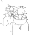
一態様においては、図1から図4、および図6に図示されるように、本発明は、(a)無人陸上ビークル20と一体化された無人航空ビークル15、(b)無人航空ビークル15および無人陸上ビークル20により共有される動力ユニット25、(c)無人航空ビークル15および無人陸上ビークル20により共有されるビークル制御装置、(d)無人航空ビークル15から無人陸上ビークル20を切り離すための係合解除機構30、(e)無人航空ビークル15もしくは無人陸上ビークル20のいずれかの上に配置された1つまたは複数のマニピュレータアーム140、ならびに(f)着陸装置35を備える変容式無人航空/陸上ビークルアセンブリ10を提供する。
In one aspect, as illustrated in FIGS. 1-4 and 6, the present invention includes (a) an unmanned aerial vehicle 15 integrated with an unmanned land vehicle 20, (b) an unmanned aerial vehicle 15 and A power unit 25 shared by the unmanned land vehicle 20; (c) a vehicle controller shared by the unmanned aerial vehicle 15 and the unmanned land vehicle 20; and (d) an engagement for disconnecting the unmanned land vehicle 20 from the unmanned aerial vehicle 15. Transforming unmanned aerial / land vehicle comprising release mechanism 30, (e) one or more manipulator arms 140 disposed on either unmanned aerial vehicle 15 or unmanned land vehicle 20, and (f)
本明細書において使用される際に、無人航空ビークル(UAV)15には、シングル・ダクト・ファン・アセンブリ(図示せず)、ダブル・ダクト・ファン・アセンブリ(図1から図4)、またはマルチ・ダクト・ファン・アセンブリ、1つもしくは複数のヘリコプタアセンブリ、または、当技術において知られている任意の他の垂直方向離陸/着陸ビークルが含まれ得る。2ダクト・ファン型の実施形態においては、これらのファンは、個々のファンにより生成されるトルクを相殺するように相互逆回転する。各実施形態は、機械駆動システムの代わりに電気モータを使用してよい。これらの多様な実施形態は、以下に詳述される。好ましくは、ダクト・ファン・アセンブリ15はそれぞれ、ダクト40、スピナ、テールコーン、ノーズコーン、ファン、ステータファン取付部、および駆動歯車135を備える。3ダクト・ファン型の実施形態においては、第3のダクト・ファンは、ダクト駆動歯車135の中の1つから延びる直角シャフトを有してよく、それにより第3のダクト・ファンに動力が伝達される。代替的には、4ダクト・ファン型の実施形態においては、機械駆動システムは、駆動歯車135を利用して4つのダクトの中の2つをそれぞれが駆動する2つのエンジンを有することが可能である。好ましくは、ヘリコプタアセンブリはそれぞれ、ハウジング、ロータ、ロータブレード、および駆動歯車を備える。 As used herein, unmanned aerial vehicle (UAV) 15 includes a single duct fan assembly (not shown), a double duct fan assembly (FIGS. 1-4), or a multi A duct fan assembly, one or more helicopter assemblies, or any other vertical takeoff / landing vehicle known in the art may be included. In a two-duct fan type embodiment, these fans rotate counterclockwise to offset the torque generated by the individual fans. Each embodiment may use an electric motor instead of a mechanical drive system. These various embodiments are described in detail below. Preferably, each duct fan assembly 15 comprises a duct 40, a spinner, a tail cone, a nose cone, a fan, a stator fan mounting, and a drive gear 135. In a three-duct fan type embodiment, the third duct fan may have a right angle shaft extending from one of the duct drive gears 135 so that power is transmitted to the third duct fan. Is done. Alternatively, in a four-duct fan type embodiment, the mechanical drive system can have two engines that each drive two of the four ducts utilizing drive gear 135. is there. Preferably, each helicopter assembly includes a housing, a rotor, a rotor blade, and a drive gear.
本明細書において使用される際に、無人陸上ビークル(UGV)20は、例えば車輪また無限軌道などの、当技術において知られている任意の陸上移動機構45を備える、任意の自律型または遠隔操作型ビークルを含んでよい。さらなる特定の実施形態が、以下において詳述される。
As used herein, an unmanned land vehicle (UGV) 20 comprises any autonomous or remote control comprising any
本明細書において使用される際に、UAV15およびUGV20により共有されるエンジンは、主として、UAV15またはUGV20のいずれかの上に配置されてよい。動力ユニット25は、当技術において既知のタイプの往復動エンジンまたはタービンエンジンを備えてよい。好ましくは、タービンエンジン25は、最大で4つまでのダクト・ファンまたはヘリコプタロータを駆動するのに十分な出力密度を有する始動発電機を有する。エンジン25から1つもしくは複数のファンまたはヘリコプタロータへのエネルギーの伝達は、差動装置/スプライン軸システム、ベルトシステム、またはチェーンシステムなどの、エネルギー伝達デバイス50を介する。代替的には、ファンまたはロータに対する機械的連結はなくてもよく、代替として、共有される動力ユニット25が、UAVの各ダクト・ファン(またはヘリコプタロータ)の下方の電気モータと、UGVの移動機構45上の電気モータとに結合される発電機を備えてよい。
As used herein, the engine shared by UAV 15 and UGV 20 may be primarily located on either UAV 15 or UGV 20. The power unit 25 may comprise a reciprocating engine or turbine engine of the type known in the art. Preferably, the turbine engine 25 has a starter generator having a power density sufficient to drive up to four duct fans or helicopter rotors. The transfer of energy from the engine 25 to one or more fans or helicopter rotors is via an
本明細書において使用される際に、ビークル制御装置は、当技術において既知のタイプの、ビークル制御アビオニクス装置およびビークル制御システムセンサを含む。より具体的には、これらの制御装置は、UAVおよびUGVの表面/ファン制御装置、ならびに移動機構45およびマニピュレータアーム140のための駆動システムを含む。さらに、この制御システムは、適切な係合位置にUGV20を誘導する役割、ならびに、係合解除機構および係合機構を作動させる役割を担う。
As used herein, vehicle control devices include vehicle control avionics devices and vehicle control system sensors of the type known in the art. More specifically, these controllers include UAV and UGV surface / fan controllers and drive systems for
本明細書において使用される際に、UAV15からUGV20を切り離すための係合解除機構30は、例えば、UGVの移動機構45、UAV15自体、および、1つまたは複数のマニピュレータアーム140などを含んでよい。さらに、係合機構およびロック機構には、ソレノイド駆動式クランプシステム、係合ロッド、ロック蟻ほぞ、ねじジャッキ、または、他の既知のクランプ機構およびロック機構が含まれ得る。例えば、UGVの移動機構45は、UGV20がUAV15の上のラッチ機構55と係合状態におよび係合解除状態になるように、UGV20を上昇および下降させることが可能であってよく、または、UGV20を前方および後方に移動させることが可能であってよい。別の実施形態においては、UAV15は、単に、飛行状態へと離昇することにより、UGV20の上のラッチ55から着陸装置35を取り外すことができる。さらなる実施形態においては、1つまたは複数のマニピュレータアーム140は、UGV20がUAV15上のラッチ機構55と係合状態におよび係合解除状態になるように、UGV20を上昇および下降させることが可能であってよく、または、UGV20を前方および後方に移動させることが可能であってよい。さらに、係合機構は、図6に図示されるような連結器もしくは着陸脚部を受容するためのコーン、基本的な楔連結部、電磁装置、または、査察カメラおよび光学処理を利用する光学システムなどの、誘導制御システムを備えてよい。
As used herein, the disengagement mechanism 30 for detaching the UGV 20 from the UAV 15 may include, for example, the
本明細書において使用される際に、UAV15またはUGV20のいずれかの上に含まれる、1つまたは複数のマニピュレータアーム140は、データを収集する、もしくは障害物を切り抜けて機動するための、センサ、クランプ、グラップル、またはクローなどのエンドエフェクタを有するロボットアームを含む。好ましくは、1つまたは複数のマニピュレータアーム140は、複数の自由度を有する。1つまたは複数のマニピュレータアーム140は、好ましくは、飛行の際に格納される。 As used herein, one or more manipulator arms 140 included on either UAV 15 or UGV 20 are sensors for collecting data or maneuvering through obstacles, Includes a robotic arm having an end effector such as a clamp, grapple, or claw. Preferably, the one or more manipulator arms 140 have a plurality of degrees of freedom. One or more manipulator arms 140 are preferably retracted during flight.
本明細書において使用される際に、着陸装置35は、収納可能型もしくは固定型のものであってよく、UGV20もしくはUAV15のいずれかに装着されてよい。好ましくは、着陸装置35は、例えばソレノイド駆動式位置決めシステムを介してなど、着陸の際の回転を防止された態様で装着された、複数の成形ロッドを含む。着陸装置ロッド35の形状は、様々であってよいが、着陸装置35が収納可能型のものである場合には、ロッド35は、好ましくは、90度回転した際にダクト40と実質的に同一平面状態に置かれるように、ダクト40の外部形状に一致する。代替的には、着陸装置35は、連接式ロッドを含んでよい。
As used herein, the
図1から図4に図示される一実施形態においては、UAV15は、第1のダクト・ファン・アセンブリ60、第2のダクト・ファン・アセンブリ65、および、第1の端部75上にて第1のダクト・ファン・アセンブリ60に対して固定され、第2の端部80上にて第2のダクト・ファン・アセンブリ65に対して固定された前方ペイロードポッド70を備える。UGV20は、動力ユニットハウジング85内に収容された動力ユニット25、動力ユニットハウジング85に連結された第1の後方ペイロードポッド90、動力ユニットハウジング85に連結された第2の後方ペイロードポッド95、動力ユニットハウジング85に可動式に連結されたベース100、および、ベース100に可動式に連結された移動機構45を備える。第1の後方ペイロードポッド90の自由端部105は、第1のダクト・ファン・アセンブリ60への連結が可能であり、第2の後方ペイロードポッド95の自由端部110は、第2のダクト・ファン・アセンブリ65への連結が可能である。本明細書において使用される際に、UAV15は、任務地にUGV20を迅速に配備するために使用される。
In one embodiment illustrated in FIGS. 1-4, the UAV 15 includes a first
本明細書において使用される際に、第1のダクト・ファン・アセンブリ60および第2のダクト・ファン・アセンブリ65の寸法は、実質的に同一である。したがって、このシステムは、左右に釣り合いがとられ、機能上の重心を保つように、前方ペイロードポッド70、後方ペイロードポッド90、95、およびUGV20の設計ならびに配置において調節がなされる。3つ以上のダクト・ファン・アセンブリ15を使用する実施形態においては、追加のダクト・ファン・アセンブリ15が、追加の固定型または取外し可能型のペイロードポッドによってともに連接される。
As used herein, the dimensions of the first
本明細書において使用される際に、前方ペイロードポッド70は、センサ、および/または、燃料タンクもしくは燃料ブラダを含む様々なペイロードを収容することができる。これらのセンサは、当技術において既知のタイプのものであり、視覚映像化装置72、または、UGV20およびUAV15の両方に共通する他の査察用ペイロードを含んでよい。これらの査察用ペイロードは、好ましくは、主としてUGV20の上に配置されるが、UAV15およびUGV20が係合される場合には、査察用ペイロードは、所望の感知視野に対する可視化を実現するように作動する。好ましくは、前方ペイロードポッド70は、前方飛行において180度またはそれ以上のセンサ視認性を有することができる。前方ペイロードポッド70は、第1のダクト・ファン・アセンブリ60と第2のダクト・ファン・アセンブリ65との間に恒久的に固定されてよく、あるいは、代替的には、ペイロードもしくはセンサの交換、または迅速な燃料補給が可能となるように、ラッチ機構55を介して固定されてもよい。前方ペイロードポッド70は、好ましくは、空力学的断面を有し、前方から見た場合には実質的に「V字型」形状であり、さらなる揚力が生成されるように、最長弦部が2つのダクト・ファン・アセンブリ60と65との間の実質的に中間に位置する。各ダクト40の前縁リップに対する重心は、前方ペイロードポッド70とダクト・ファン・アセンブリ60、65との間の装着箇所75、80の位置によって維持され、さらに、前方ペイロードポッド70の可搬重量によって維持される。さらに、重心、および前方ペイロードポッドの装着箇所75、80の位置は、以下においてより詳細に説明されるように、UGVの後方ペイロードポッド90、95とダクト・ファン・アセンブリ60、65との間の装着箇所の位置によっても決定される。
As used herein, the forward payload pod 70 can house a variety of payloads including sensors and / or fuel tanks or fuel bladders. These sensors are of a type known in the art and may include a
本明細書において使用される際に、動力ユニット25は、タービンエンジン、往復動エンジン、発電機、または、当技術において知られている任意の他の動力源であってよい。動力ユニット25が、例えばタービンエンジンまたは往復動エンジンである場合には、駆動歯車は、ファン115が相互逆回転式となるように、相互逆回転式のものである。図5において詳細に図示されるように、動力は、例えば差動装置120に供給され、エンジン25から、動力ユニットハウジング85から延在する引戻り可能なスプライン軸継手132まで伝達される。差動装置120は、この動力を、各プロップの下方の直角歯車135にそれぞれ連結された2つのスプライン軸130を介して、ダクト・ファン・アセンブリ60、65に伝達する。出力軸130の相対速度は、速度ブレーキにより、または軸負荷システムを介して、制動力をスプライン軸130に個別に印加することによって、制御される。速度ブレーキは、可変式負荷制御装置を有する摩擦起電機または発電機のいずれかが可能である。スプライン軸継手125は、UAV15からの係合解除のために動力ユニットハウジング85内に引き戻ることが可能であり、UAV15との再係合のために延出することが可能であり、好ましくは、差動装置120と容易に対合するようにテーパ状になされる。図5は、ファンを駆動するためにダクト・ファン・アセンブリ60、65と係合されたスプライン軸130を示す。UGV20は、UGV20の中心の方向に内方にスプライン軸継手132を摺動させることによって、UAVファンから係合解除する、およびUGV駆動機構136と係合する。2つのダクト・ファン・アセンブリ60、65を上回る個数のダクト・ファン・アセンブリを有する実施形態については、差動装置は、同数のスプライン軸を駆動するように構成される。動力ユニット25が、発電機である場合には、電力は、UGVの後方ペイロードポッド90、95とUAVのダクト40との間の電気的結合部を介して供給され、電気モータが、電子速度制御装置とともにファンを駆動する。
As used herein, power unit 25 may be a turbine engine, a reciprocating engine, a generator, or any other power source known in the art. When the power unit 25 is, for example, a turbine engine or a reciprocating engine, the drive gear is of a mutually reverse rotation type so that the
本明細書において使用される際に、動力ユニットハウジング85は、好ましくは、平滑な空力学的形状および表面と、他の空力学的特性とを有する。例えば、動力ユニットハウジング85は、エンジン排気出口180についてテールコーンを有してよい。さらに、動力ユニットハウジング85は、エンジン制御装置を収容してよい。
As used herein, the
本明細書において使用される際に、後方ペイロードポッド90、95は、好ましくは、空力学的断面を有する。第1および第2の後方ペイロードポッド90、95は、UGVの動力ユニットハウジング85に対して恒久的に固定されてよく、または、代替的には、ペイロードもしくはセンサの交換が可能となるようにラッチ機構55を介して固定されてもよい。後方ペイロードポッド90、95は、好ましくは、機能上の重心を維持するために、UGVの重量が変容式無人航空/陸上ビークルアセンブリ10の中心のより近くに集中するように、UGVの動力ユニットハウジング85の前方側よりも後方側により近い位置に装着される。第1および第2の後方ペイロードポッド90、95の自由端部105、110は、ラッチ機構55を介して、第1および第2のダクト・ファン・アセンブリ60、65にそれぞれ固定され、それにより、UGV20をUAV15から係合解除すること、およびUAV15に再係合させることが可能となる。重心を維持するために、ダクト・ファン・アセンブリ60、65に対する後方ペイロードポッド90、95の装着箇所の位置は、後方ペイロードポッド90、95の可搬重量、UGV20の重量、ならびに、前方ペイロードポッド70の位置および重量によって、決定される。さらに、第1および第2の後方ペイロードポッド90、95は、1つまたは複数のマニピュレータアーム140を収容してよい。
As used herein, the
さらに、後方ペイロードポッド90、95は、共有されるビークル制御装置を収容してよい。後方ペイロードポッド90、95が、動力ユニットハウジング85の代わりにビークル制御装置を収容する場合には、後方ペイロードポッド90、95は、UAV15から係合解除される際に、UGV20が作動不能にならないように、UGV20に装着された状態に留まらなければならない。動力ユニットハウジング85が、ビークル制御装置を収容する場合には、後方ペイロードポッド90、95は、UGV20がUAV15から係合解除される際に、UAV15に装着されたままであってよい。代替的には、無線通信を利用する一実施形態においては、ビークル制御装置の複数部分が、UGV20またはUAV15のいずれかの上に含まれてよく、ビークル制御装置は、UAV15にUGV20を再接合するための再係合指令信号を含んでよい。
Further, the
本明細書において使用される際に、ベースは、動力ユニットハウジング85の前方側の上の箇所から動力ユニットハウジング85の底部側まで実質的に垂直方向に下方に延在するスロット内を移動し得る、少なくとも1つの剛性部材を介して、動力ユニットハウジング85に可動式に連結される。このスロットにより、ベース100は、地面に対して平行である実質的に水平な位置から実質的に垂直な位置へと移動することが可能となる。ビークル制御装置に結合された電気モータが、スロットに沿った適切な方向に剛体部材およびベース100を駆動させるように、前方モードおよび後方モードで作動する。泥および水などの汚染物質が動力ユニットハウジング85内に進入するのを防ぐために、スロットは、例えば、ゴムフラップ、一群の剛質のブリストル、または、両端部にて剛体部材に装着される可動式無限軌道などに沿って並べられてよい。
As used herein, the base may move in a slot that extends substantially vertically downward from a location on the front side of the
本明細書において使用される際に、移動機構45は、当技術において既知のタイプの懸架装置によりベース100に可動式に連結された、車輪、無限軌道、または、当技術において知られている他の任意のタイプの移動機構45を含んでよい。地形適応能力は、UGVの重心および傾斜角度によって決定される。例えば無限軌道または車輪の間の距離を広げることによって、より大きな傾斜角度に対応することが可能なより大きなベースが作製される。移動機構45は、上述の態様において、動力ユニット25により動力供給される。例えば、動力ユニット25が、発電機である場合には、発電機25は、電力を電気モータに伝達し、次いで、この電気モータは、当技術において既知のシステムを利用して移動機構45を駆動する。同様に、動力ユニット25が、エンジンである場合には、エンジン25は、動力を差動装置に伝達し、次いで、この差動装置は、移動機構45に連結されたスプライン軸に対して動力を伝達する。
As used herein, the moving
さらに、移動機構45は、もう1つの点において、ベース100に可動式に連結される。移動機構45は、以下において詳述されるように、UGV20がUAV15と係合されるまたは一体化される際に、ベース内にまたはベースの下方に移行することにより、ベース100に対して移動する。
Further, the
一実施形態においては、UGV20は、飛行のための格納位置と、陸上移動のための作動位置との間で移行することが可能である。本明細書において使用される際に、格納位置は、UGV20およびUAV15が一体化されまたは係合され、移動機構45が地面との接触状態から移動し、空力学的様式で格納されることを意味する。これは、ベース100が動力ユニットハウジング85の下方にて保護されるように、地面から移動機構45を単に上昇させることにより、達成され得る。代替的には、図3から図4に図示されるように、UGV20は、第1および第2の後方ペイロードポッド90、95を介してUAV15に固定され、ベース100は、ベース100の底部が前方ペイロードポッド70に対面し、ベース100の頂部が動力ユニットハウジング85に対面し、ベース100の各側部がダクト・ファン・アセンブリ60、65の一方に対面するように、実質的に垂直位置まで回転される。格納位置においては、ベース100は、好ましくは、ビークル制御装置に結合される、例えばソレノイド駆動式解除ラッチ55などを介して、第1および第2のダクト・ファン・アセンブリ60、65にロックされる。
In one embodiment, the UGV 20 is capable of transitioning between a retracted position for flight and an operational position for land movement. As used herein, the retracted position means that the UGV 20 and UAV 15 are integrated or engaged and the moving
本明細書において使用される際に、作動位置は、ベース100が実質的に水平な位置まで回転され、UGV20およびUAV15が係合解除され、または係合解除可能な状態になされ、移動機構45が地面に接触することが可能であることを意味する。UGV20が、UAV15からの切離しの前に作動位置に移行する際には、移動機構45は、ベース100から完全に延伸され、または広げられ、作動可能となる。UGV20およびUAV15が、ラッチ機構55にて結合される際には、スプライン軸継手132は、UAV駆動軸130と係合するように、および移動用駆動装置136から係合解除されるように、摺動する。次いで、移動用無限軌道30、45が、ベース100内の格納位置まで回転され上げられる。ベース100は、飛行の際の移動用無限軌道30、45用の空力学的筐体を形成する。移動機構45は、機械的システムが、初めに地面から移動用無限軌道を上昇させ、ベース100内に摺動させることによって、ベース100に折り重ねられる。次いで、移動用無限軌道30、45を収容するベース100が、回転され、2つのUAVダクト・ファン・アセンブリ60、65の間中に上昇される。
As used herein, the operating position is such that the
一実施形態においては、ベースは、空力学的に形状設定される。本明細書において使用される際に、ベース100が、図2に図示されるように、格納位置にあり、実質的に垂直方向に位置する場合には、空力学的断面は、飛行に適する方向に向いている。同様に、ベース100が、図1に図示されるように、作動位置にあり、実質的に水平方向に位置する場合には、空力学的断面は、地面に沿った前進運動に適した方向に向いている。
In one embodiment, the base is aerodynamically shaped. As used herein, when the
一実施形態においては、UGV20は、ラッチ機構55を介してUAV15と一体化され、ラッチ機構55により、UGV20およびUAV15の両方の上に含まれる電気接続器ピンの適切な位置合わせが確保される。本明細書において使用される際に、ラッチ機構55は、ビークル制御装置に結合されるソレノイド駆動式ラッチまたは蟻ほぞラッチを含んでよい。ソレノイド駆動式ラッチおよび蟻ほぞラッチが述べられるが、本開示は、装着方法を限定するように意図されない。任意の他のよく知られている装着方法を使用することが可能である。第1および第2の後方ペイロードポッド90、95の自由端部105、110がそれぞれ、ラッチ機構55に装着され、ダクト・ファン・アセンブリ60、65がそれぞれ、対応するラッチ機構55に装着される。さらに、後方ペイロードポッド90、95がUGV20から取外し可能である一実施形態においては、後方ペイロードポッド90、95はそれぞれ、追加のラッチ機構55に装着され、UGV20は、対応するラッチ機構55に装着される。雄ラッチ機構55を受ける雌ラッチ機構55は、好ましくは、後方ペイロードポッドのラッチ機構55を、ダクト・ファン・アセンブリ15およびUGV20の上の対応するラッチ機構55内に誘導するのを補助するように、テーパ状になされた比較的広い開口を有する。
In one embodiment, the UGV 20 is integrated with the UAV 15 via a
さらに、ラッチ機構55は、実質的に垂直方向または水平方向に配向されてよい。さらに、ラッチ機構55は、角度をつけられてもよい。ラッチ機構55が、垂直方向に配置される場合には、後方ペイロードポッドのラッチ機構55は、上昇または下降されて移動機構45により係合された状態もしくは移動機構45から係合解除された状態となることによって、UAVのラッチ機構55に係合すること、またはUAVのラッチ機構55から係合解除することが可能である。別の実施形態においては、UGVのラッチ機構55は、上昇または下降されて係合状態もしくは係合解除状態になることによって、後方ペイロードポッドのラッチ機構55に係合すること、または後方ペイロードポッドのラッチ機構55から係合解除することが可能である。ラッチ機構55が、水平方向に配置される場合には、後方ペイロードポッドのラッチ機構55は、UGVの移動機構45が前方または後方に移動することによって、UAVのラッチ機構55に係合すること、またはUAVのラッチ機構55から係合解除することが可能である。別の実施形態においては、UGVのラッチ機構55は、UGVの移動機構45が前方または後方に移動することによって、後方ペイロードポッドのラッチ機構55と係合すること、または後方ペイロードポッドのラッチ機構55から係合解除することが可能である。
Further, the
さらに、各ラッチ機構55は、UGV20がUAV15と再係合する際の位置合わせを補助するための、サーボ駆動式垂直方向調節装置を有する。しかし、この一次調節は、UAV15に対する移動機構の接近により遂行され得る主要な補正を伴う、水平方向に対するものであってよい。追加的な微細な位置調節は、機械的誘導部によって、または、短距離垂直方向および水平方向サーボラッチを介して、遂行されてよい。代替的なアプローチは、UGV20を固定ロック位置に引く回転スパイラルラッチを利用することである。
In addition, each
一実施形態においては、移動機構45は、デュアルセットの無限軌道である。無限軌道45は、前方端部および後方端部がローラの周囲にて懸架される、可撓性の踏進ベルトを含んでよい。代替的には、無限軌道45は、互いに接合され、前方端部および後方端部にてローラの周囲に懸架される、複数の剛性ユニットを含んでよい。
In one embodiment, the moving
一実施形態においては、係合解除機構30は、デュアルセットの無限軌道を含む。この係合解除機構30は、地面に接触するまで地面の方向に無限軌道の前方端部を回転させること、および、地面に対して前方端部を押圧して、UGV20を上昇させ、ラッチ機構55から外れさせることによって、UAV15からUGV20を係合解除し、無限軌道の後方端部を上方に回転させて、UGV20を上昇させ、ラッチ機構55上に上げること、および、ラッチ機構55内にUGV20を下げることによって、UAV15にUGV20を再係合させる。
In one embodiment, the disengagement mechanism 30 includes a dual set of endless tracks. The disengagement mechanism 30 rotates the front end of the endless track in the direction of the ground until it contacts the ground, and presses the front end against the ground to raise the UGV 20, and the
一実施形態においては、1つまたは複数のマニピュレータアーム140の中の1つが、動力ユニットハウジング85の頂部内に収容される。マニピュレータアーム140は、地面に達するのに十分な程度まで延伸可能な少なくとも3自由度を有する。マニピュレータアーム140は、サーボ駆動式方位角制御装置、2つのサーボ駆動式エルボ、ねじ駆動式長手方向被動延伸可能部材、およびアーム端部の工具制御装置を備えてよい。
In one embodiment, one of the one or more manipulator arms 140 is housed within the top of the
一実施形態においては、UAV15は、共有される動力ユニット25およびビークル制御装置を収容するダクト・ファン・アセンブリを備え、恒久的に延在する着陸装置35を有する。このUGV20は、全地形対応ビークルの上面の上に形成された着陸プラットフォーム145と、全地形対応ビークルのハウジングに一体化される1つまたは複数のペイロードポッド(図示せず)とを有する、全地形対応ビークルを備える。このUAV15の着陸装置35は、UGV20の着陸プラットフォーム145中に含まれる複数の着陸装置レセプタクル155によって受けられる。本明細書において使用される際に、このUGV20は、UAV15の任務遂行地にUAV15を送るために使用される。さらに、UAV15は、雨裂または河川などの地上の障害を回避するために、UGV20を上昇させることが可能である。
In one embodiment, UAV 15 includes a
本明細書において使用される際に、このUGV20は、好ましくは、最高の移動性および障害物迂回性の能力を有する、民生型の全地形対応ビークルを含む。代替的には、UGV20は、無限軌道ビークル、または、無限軌道および車輪の両方を備えたビークルを含んでよい。無人航空ビークルのハウジングに一体化されるペイロードポッドは、センサ、付加燃料、または、任意の他の任務に適した貨物を収容してよい。 As used herein, the UGV 20 preferably includes a consumer-type all-terrain vehicle with the highest mobility and obstacle bypass capability. Alternatively, the UGV 20 may include an endless track vehicle or a vehicle with both endless tracks and wheels. A payload pod that is integrated into the housing of an unmanned aerial vehicle may contain sensors, supplemental fuel, or cargo suitable for any other mission.
UGV20およびUAV15が、一体化され、陸上移動が可能な状態になされると、UAVの着陸装置35は、UGVの着陸プラットフォーム145の上の着陸装置レセプタクル内のソレノイドラッチ55を介して定位置にロックされる。これらのソレノイドラッチ55は、ビークル制御装置によって作動される。複数のシングル・ダクトUAV15を有する一実施形態においては、着陸プラットフォーム145は、各UAV15に対する着陸装置レセプタクル155を含むように、構成される。そして各UAV15は、UAV15およびUGV20の両方に対するビークル制御装置を収容し、これによって必ず、1つまたは複数のUAV15が任務中に行方不明になった場合でも、残りのUAV15が依然としてUGV20に再係合し、その動作を制御することが可能となる。
Once the UGV 20 and UAV 15 are integrated and ready for land movement, the
本明細書において使用される際に、動力ユニット25は、タービンエンジン、往復動エンジン、発電機、または、当技術において知られている任意の他の動力源であってよい。動力ユニット25が、例えばタービンエンジンまたは往復動エンジンである場合には、エンジンは、動力ユニットハウジング85から着陸プラットフォーム145中の開口(図示せず)を貫通して延在する引戻り可能なスプライン軸継手125を介して、例えばUGV20内に収容された差動装置120に、動力を伝達する。このスプライン軸継手125は、UAV15から係合解除するために、動力ユニットハウジング85内に引き戻すことが可能であり、UAV15と再係合するために延伸することが可能であり、好ましくは、差動装置120との係合を容易にするようにテーパ状になされる。着陸プラットフォーム145中の開口は、延伸するスプライン軸継手125から圧力が加えられると側方に摺動し、スプライン軸継手125が取り除かれると定位置に戻る、ばね付きカバーを有してよい。差動装置120は、スプライン軸継手125から、UGVの伝達システムに組み込まれるスプライン軸130に、動力を伝達する。3つ以上のダクト・ファン・アセンブリを有する実施形態については、伝達システムのセグメントを駆動するように構成された、対応する差動装置が設けられる。動力ユニット25が、発電機である場合には、電力が、UGVの着陸装置レセプタクル155およびUAVの着陸装置35中に含まれる電気的結合部を介して供給され、電気モータが、電子速度制御装置とともに、UGV20およびUAVのファンを駆動させる。
As used herein, power unit 25 may be a turbine engine, a reciprocating engine, a generator, or any other power source known in the art. If the power unit 25 is a turbine engine or a reciprocating engine, for example, the engine is a retractable spline shaft that extends from the
一実施形態においては、着陸装置35は、複数の実質的に剛性の脚部を備え、複数の着陸装置レセプタクル155は、ラッチ機構(図6には図示せず)と適切に位置合わせされる状態に着陸装置35を誘導するように、円錐状に形状設定される。着陸プラットフォーム145は、実質的に平坦であり、好ましくは、その表面上に、着陸装置レセプタクル155の位置に対応する「X」などの誘導マーカを含む。UAVのセンサペイロードは、誘導マーカのリアルタイム画像を遠隔地の操作者に送信することが可能であり、この操作者は、UGV20と再係合させる際に、UAVの位置を制御し、着陸装置レセプタクル155に着陸装置35を位置合わせすることが可能となる。着陸装置レセプタクル155が円錐形状であることにより、各剛性脚部35に対する表面区域着陸ゾーンが拡大することによって、UAV15の着陸時の誤差の許容範囲が広がる。剛性脚部35が、コーン、即ち着陸プラットフォーム145の内部に接触すると、脚部35は、着陸プラットフォーム145中に摺動して下がり、好ましくはソレノイド作動式ラッチ機構によって定位置にロックされる。
In one embodiment, the
ラッチ機構は、多数の様式で作動され得る。一実施形態においては、ラッチ機構は、複数の着陸装置レセプタクルのそれぞれに対応する複数のソレノイドラッチを備える。例えば、剛性脚部35は、それらの基部付近に貫通孔を含んでよく、これらの貫通孔内に、ソレノイド作動式ボルトが、ラッチ機構によって挿入される。代替的には、剛性脚部35は、それらの基部付近にテーパ状リップを備えてよく、このテーパ状リップにより、各脚部35が適切に位置合わせされた状態に容易に摺動することが可能となるとともに、定位置に摺動するソレノイド作動式ラッチによってクランプ締めされ得る表面が形成される。
The latch mechanism can be actuated in a number of ways. In one embodiment, the latch mechanism includes a plurality of solenoid latches corresponding to each of the plurality of landing gear receptacles. For example, the
ラッチ機構は、一体化されたUGV20およびUAV15が飛行状態にある場合に、ロック位置に留まるのに十分な強度のものでなければならない。剛性脚部35およびUAV15への連結部は、障害物を避けるための短距離飛行に対してUGV20の重量を支持するのに十分な強度のものでなければならない。剛性脚部35は、好ましくは、軽量高強度複合構造体から作製される。剛性脚部35は、UAVダクトの内部構造部に連結され、空力学的表面を構造力から分離された状態に維持する。剛性脚部35は、下層の骨格構造部に恒久的に接合もしくは溶接されてよく、または、定位置にボルト留めされてよい。
The latch mechanism must be strong enough to remain in the locked position when the integrated UGV 20 and UAV 15 are in flight. The
一実施形態においては、着陸装置35は、UAV15とUGV20との間において電力および制御信号を伝送するための電気接続器ピンのインターフェースを形成する。着陸装置レセプタクル155により、着陸装置の電気接続器ピンの、着陸プラットフォーム145中の相補的な電気接続器ピンとの適切な位置合わせが確保される。これらの接続器ピンは、UAV15およびUGV20に搭載された電線および/または光ファイバを介して、ビークル制御装置に接続される。
In one embodiment,
一実施形態においては、着陸装置35は、実質的に剛性の脚部35のそれぞれの端部上にて、ばね付きキャップ(図示せず)によって保護される。着陸装置35が、着陸装置レセプタクル155と接触すると、ばね付きキャップにかかる圧力によって、キャップは側方に摺動し、着陸装置レセプタクル155の基部は、キャップの体積部を収容するような構成になされる。代替的には、キャップは、アビオニクス制御装置からの信号に応じて、または、着陸装置レセプタクル155内のメカニカル・キーを介して作動する。
In one embodiment, the
一実施形態においては、係合解除機構30は、UAV15自体を含み、UAV15は、離陸によってUGV20から係合解除され、着陸プラットフォーム145の上への着陸によって再係合される。
In one embodiment, the disengagement mechanism 30 includes the UAV 15 itself, which is disengaged from the UGV 20 by takeoff and reengaged by landing on the
10 変容式無人航空/陸上ビークルアセンブリ
15 無人航空ビークル、UAV、ダクト・ファン・アセンブリ
20 無人陸上ビークル、UGV
25 動力ユニット、エンジン、出力ユニット、タービンエンジン、発電機
30 係合解除機構、移動用無限軌道
35 着陸装置、剛性脚部、着陸装置ロッド
40 ダクト
45 陸上移動機構、移動用無限軌道
50 エネルギー伝達デバイス
55 ラッチ機構
60 第1のダクト・ファン・アセンブリ
65 第2のダクト・ファン・アセンブリ
70 前方ペイロードポッド
72 視覚映像化装置
75 第1の端部
80 第2の端部
85 動力ユニットハウジング
90 第1の後方ペイロードポッド
95 第2の後方ペイロードポッド
100 ベース
105 自由端部
110 自由端部
115 ファン
120 差動装置
125 スプライン軸継手
130 スプライン軸、出力軸、UAV駆動軸
132 スプライン軸継手
135 駆動歯車、直角歯車
136 UGV駆動機構、移動用駆動装置
140 マニピュレータアーム
145 着陸プラットフォーム、コーン
155 着陸装置レセプタクル
180 エンジン排気出口
10 Transform unmanned aerial vehicle / land vehicle assembly 15 Unmanned aerial vehicle, UAV, duct fan assembly 20 Unmanned land vehicle, UGV
25 Power unit, engine, output unit, turbine engine, generator 30 Disengagement mechanism, moving
Claims (3)
前記無人航空ビークルおよび前記無人陸上ビークルによって共有される動力ユニットと、
前記無人航空ビークルおよび前記無人陸上ビークルによって共有されるビークル制御装置と、
前記無人航空ビークルから前記無人陸上ビークルを切り離すための係合解除機構と、
前記無人航空ビークルもしくは前記無人陸上ビークルのいずれかに配置された1つまたは複数のマニピュレータアームと、
着陸装置と
を備える変容式無人航空/陸上ビークルアセンブリ。 An unmanned aerial vehicle integrated with an unmanned aerial vehicle , wherein the integration between the unmanned aerial vehicle and the unmanned aerial vehicle supports the weight of the unmanned aerial vehicle during the flight of the unmanned aerial vehicle. Said unmanned aerial vehicle having sufficient strength to
A power unit shared by the unmanned aerial vehicle and the unmanned land vehicle;
A vehicle controller shared by the unmanned aerial vehicle and the unmanned land vehicle;
A disengagement mechanism for separating the unmanned land vehicle from the unmanned aerial vehicle;
One or more manipulator arms disposed in either the unmanned aerial vehicle or the unmanned land vehicle;
Transforming unmanned aerial / land vehicle assembly with landing gear.
前記無人航空ビークルと前記無人陸上ビークルとによって共有された動力ユニットと、A power unit shared by the unmanned aerial vehicle and the unmanned land vehicle;
前記無人航空ビークルと前記無人陸上ビークルとによって共有されたビークル制御装置と、A vehicle control device shared by the unmanned aerial vehicle and the unmanned land vehicle;
前記無人陸上ビークルを前記無人航空ビークルから切り離すための係合解除機構と、A disengagement mechanism for detaching the unmanned land vehicle from the unmanned aerial vehicle;
前記無人航空ビークルと前記無人陸上ビークルのいずれかの上に配置される1つまたは複数のマニピュレータアームとを備え、Comprising one or more manipulator arms disposed on either the unmanned aerial vehicle and the unmanned land vehicle;
前記方法が更に、前記係合解除機構で、前記無人航空ビークルから前記無人陸上ビークルを係合解除する工程を有する、方法。The method further comprises disengaging the unmanned land vehicle from the unmanned aerial vehicle with the disengagement mechanism.
Applications Claiming Priority (2)
| Application Number | Priority Date | Filing Date | Title |
|---|---|---|---|
| US12/364,762 US8205820B2 (en) | 2009-02-03 | 2009-02-03 | Transforming unmanned aerial-to-ground vehicle |
| US12/364,762 | 2009-02-03 |
Publications (3)
| Publication Number | Publication Date |
|---|---|
| JP2010179914A JP2010179914A (en) | 2010-08-19 |
| JP2010179914A5 JP2010179914A5 (en) | 2013-03-21 |
| JP5550930B2 true JP5550930B2 (en) | 2014-07-16 |
Family
ID=41694627
Family Applications (1)
| Application Number | Title | Priority Date | Filing Date |
|---|---|---|---|
| JP2010020310A Expired - Fee Related JP5550930B2 (en) | 2009-02-03 | 2010-02-01 | Transform unmanned aerial / land vehicle |
Country Status (3)
| Country | Link |
|---|---|
| US (1) | US8205820B2 (en) |
| EP (1) | EP2213570A3 (en) |
| JP (1) | JP5550930B2 (en) |
Families Citing this family (65)
| Publication number | Priority date | Publication date | Assignee | Title |
|---|---|---|---|---|
| US8181906B2 (en) * | 2009-04-02 | 2012-05-22 | Raytheon Company | Method and apparatus for ram deceleration in a launch system |
| US8590828B2 (en) | 2010-02-24 | 2013-11-26 | Robert Marcus | Rotocraft |
| US8167234B1 (en) * | 2010-03-21 | 2012-05-01 | Michael Moore | Insect-like micro air vehicle having perching, energy scavenging, crawling, and offensive payload capabilities |
| US9987506B2 (en) | 2010-12-15 | 2018-06-05 | Robert Marcus | UAV—or personal flying device—delivered deployable descent device |
| US9183638B2 (en) * | 2011-08-09 | 2015-11-10 | The Boeing Company | Image based position determination |
| US20130134254A1 (en) * | 2011-11-29 | 2013-05-30 | Jason Moore | UAV Fire-fighting System |
| CA2787279C (en) | 2012-08-29 | 2013-10-22 | Draganfly Holdings Inc. | Vehicle with aerial and ground mobility |
| US10066510B2 (en) | 2013-03-15 | 2018-09-04 | United Technologies Corporation | Nacelle mounted latching system |
| US9321529B1 (en) | 2013-04-09 | 2016-04-26 | The United States Of America, As Represented By The Secretary Of The Navy | Hybrid mobile buoy for persistent surface and underwater exploration |
| US9580172B2 (en) * | 2013-09-13 | 2017-02-28 | Sandia Corporation | Multiple environment unmanned vehicle |
| US9464902B2 (en) * | 2013-09-27 | 2016-10-11 | Regents Of The University Of Minnesota | Symbiotic unmanned aerial vehicle and unmanned surface vehicle system |
| WO2015108588A2 (en) * | 2013-10-21 | 2015-07-23 | Kespry, Inc. | Systems and methods for unmanned aerial vehicle landing |
| US20160111007A1 (en) | 2013-10-21 | 2016-04-21 | Rhett Rodney Dennerline | Database System To Organize Selectable Items For Users Related to Route Planning |
| JP6338911B2 (en) * | 2014-03-28 | 2018-06-06 | 三菱重工業株式会社 | Unmanned aerial vehicle mounting and module armor |
| US9457900B1 (en) | 2014-04-07 | 2016-10-04 | The United States Of America, As Represented By The Secretary Of The Navy | Multirotor mobile buoy for persistent surface and underwater exploration |
| US9676479B2 (en) * | 2014-05-07 | 2017-06-13 | XTI Aircraft Company | VTOL aircraft |
| CN103935418B (en) * | 2014-05-09 | 2016-06-08 | 张培贵 | Airborne carrier |
| US10239638B1 (en) | 2014-05-10 | 2019-03-26 | Wing Aviation Llc | Home station for unmanned aerial vehicle |
| CN112359892A (en) * | 2014-06-20 | 2021-02-12 | 住友重机械工业株式会社 | Shovel, shovel control method, and topographic data update method |
| US10434885B2 (en) * | 2014-08-05 | 2019-10-08 | Telecom Italia S.P.A. | Landing platform for an unmanned aerial vehicle |
| US9630710B2 (en) | 2014-10-29 | 2017-04-25 | Qualcomm Incorporated | Unmanned aerial vehicle |
| US9550400B2 (en) | 2014-10-29 | 2017-01-24 | Qualcomm Incorporated | Unmanned aerial vehicle |
| US9688400B2 (en) | 2014-10-29 | 2017-06-27 | Qualcomm Incorporated | Unmanned aerial vehicle |
| US11338634B1 (en) * | 2014-10-30 | 2022-05-24 | Robotic Research Opco, Llc | Vehicle capable of multiple varieties of locomotion |
| US9623968B2 (en) * | 2014-11-11 | 2017-04-18 | Jon RIMANELLI | Unmanned air-ground vehicle |
| US9764837B2 (en) * | 2014-11-14 | 2017-09-19 | Top Flight Technologies, Inc. | Micro hybrid generator system drone |
| CN104589941B (en) * | 2015-01-20 | 2017-02-22 | 成都脑动力科技有限公司 | Tumbler one-wheel flying car |
| ES2905883T3 (en) * | 2015-01-21 | 2022-04-12 | Univ Ramot | agricultural robot |
| JP6713984B2 (en) * | 2015-03-11 | 2020-06-24 | 学校法人千葉工業大学 | Carrier with heliport |
| MX2017012941A (en) * | 2015-04-06 | 2018-11-09 | Archon Tech S R L | Ground movement system plugin for vertical take off and landing unmanned aerial vehicles. |
| US9894327B1 (en) * | 2015-06-22 | 2018-02-13 | State Farm Mutual Automobile Insurance Company | Systems and methods for remote data collection using unmanned vehicles |
| CN107924190A (en) | 2015-06-23 | 2018-04-17 | 阿肯技术公司 | For being supported by recharging station with the system of the autonomous operation of multiple mixing unmanned vehicles of execution service |
| CN113581464A (en) | 2015-09-11 | 2021-11-02 | 深圳市大疆灵眸科技有限公司 | Carrier for unmanned aerial vehicle |
| CN105416585B (en) * | 2015-11-25 | 2018-02-06 | 上海云犀智能系统有限公司 | Can free switching motor pattern unmanned plane |
| US10787256B2 (en) | 2016-01-29 | 2020-09-29 | Lta Corporation | Aeronautical car and associated features |
| US10162348B1 (en) * | 2016-02-04 | 2018-12-25 | United Services Automobile Association (Usaa) | Unmanned vehicle morphing |
| JP6691794B2 (en) | 2016-02-26 | 2020-05-13 | 三菱重工業株式会社 | Aircraft takeoff / landing support device and flight device |
| JP6844097B2 (en) * | 2016-04-19 | 2021-03-17 | インダストリーネットワーク株式会社 | Drone flying object |
| IL247772B (en) * | 2016-09-12 | 2022-05-01 | Israel Aerospace Ind Ltd | Modular vehicle system |
| DE102016120058B4 (en) * | 2016-10-20 | 2022-12-29 | Deutsche Post Ag | averting a threat |
| US20180117981A1 (en) | 2016-10-27 | 2018-05-03 | Alberto Daniel Lacaze | Vehicle Capable of Multiple Varieties of Locomotion |
| CN106516089B (en) * | 2016-10-28 | 2019-05-21 | 深圳市道通智能航空技术有限公司 | Unmanned plane |
| US10514690B1 (en) | 2016-11-15 | 2019-12-24 | Amazon Technologies, Inc. | Cooperative autonomous aerial and ground vehicles for item delivery |
| US11057498B1 (en) * | 2016-12-30 | 2021-07-06 | Equinix, Inc. | Inter-data center data transfer using unmanned vehicles |
| WO2018133822A1 (en) * | 2017-01-18 | 2018-07-26 | 苏州宝时得电动工具有限公司 | Self-moving device and automatic working method thereof |
| US11208197B2 (en) | 2017-03-31 | 2021-12-28 | Heka Aero LLC | Gimbaled fan |
| DE102017211370B4 (en) * | 2017-07-04 | 2021-01-14 | Audi Ag | Method for operating an aircraft and aircraft |
| CN107914867B (en) * | 2017-12-06 | 2023-10-27 | 南京航空航天大学 | Friction locking self-adaptive deformation landing gear and control method thereof |
| US10875644B2 (en) * | 2017-12-28 | 2020-12-29 | Aurora Flight Sciences Corporation | Ground manipulation system and method for fixing an aircraft |
| US11401051B2 (en) * | 2018-02-19 | 2022-08-02 | The Boeing Company | Aircraft inspection systems and methods |
| US11660920B2 (en) | 2018-02-28 | 2023-05-30 | Stmicroelectronics S.R.L. | Multi-environment flexible vehicle |
| US10890921B2 (en) * | 2018-05-31 | 2021-01-12 | Carla R. Gillett | Robot and drone array |
| US11453498B2 (en) * | 2018-07-27 | 2022-09-27 | The Boeing Company | Payload engagement systems and related methods |
| US11174027B2 (en) * | 2018-07-27 | 2021-11-16 | The Boeing Company | Vehicle docking systems, payload transfer systems, and related methods |
| US20200148349A1 (en) * | 2018-11-13 | 2020-05-14 | Aurora Flight Sciences Corporation | Systems and Methods for Aerial Package Pickup and Delivery |
| KR102119424B1 (en) * | 2018-12-03 | 2020-06-08 | 순천향대학교 산학협력단 | Multipurpose Drones |
| WO2020174648A1 (en) * | 2019-02-28 | 2020-09-03 | ヤマトホールディングス株式会社 | Pod and drone system |
| US11340618B2 (en) | 2019-08-08 | 2022-05-24 | Robotic Research Opco, Llc | Drone based inspection system at railroad crossings |
| US11247089B2 (en) | 2019-08-22 | 2022-02-15 | Robotic Research Opco, Llc | Chemical and biological warfare agent decontamination drone |
| DE102019132056A1 (en) * | 2019-11-26 | 2021-05-27 | Heggemann Ag | Carrier trolley for STOL / VTOL aircraft |
| CN110979632A (en) * | 2019-11-28 | 2020-04-10 | 成都智巡科技有限责任公司 | Unmanned aerial vehicle layout structure |
| CN110978921A (en) * | 2019-12-22 | 2020-04-10 | 长春工程学院 | Land all-terrain duct cross-domain robot and cross-domain method thereof |
| US11851178B2 (en) * | 2020-02-14 | 2023-12-26 | The Aerospace Corporation | Long range endurance aero platform system |
| KR102309477B1 (en) * | 2020-05-19 | 2021-10-06 | 한기남 | Device for measuring mud flat using dron |
| WO2023037437A1 (en) * | 2021-09-08 | 2023-03-16 | 東京ロボティクス株式会社 | Unmanned aerial vehicle, flying body, and flying robot |
Family Cites Families (46)
| Publication number | Priority date | Publication date | Assignee | Title |
|---|---|---|---|---|
| FR1328507A (en) * | 1962-04-19 | 1963-05-31 | Transport device convertible into an automobile or airplane | |
| FR1566327A (en) * | 1968-02-01 | 1969-05-09 | ||
| US4171784A (en) * | 1971-03-08 | 1979-10-23 | Karl Eickmann | Combination road and air vehicle having a lowerable chassis |
| US4173321A (en) * | 1971-03-08 | 1979-11-06 | Karl Eickmann | Vehicle for traveling in the air and on the ground equipped with hydraulically driven propellers |
| US3761040A (en) * | 1972-03-08 | 1973-09-25 | P Cummins | Remote controlled helicopter transport device and method |
| US4678141A (en) * | 1981-03-16 | 1987-07-07 | Grumman Aerospace Corporation | Aircraft launcher and retriever |
| JPS6237000U (en) * | 1985-08-26 | 1987-03-04 | ||
| JPH0724751A (en) * | 1989-02-13 | 1995-01-27 | Toshiba Corp | Inspection work robot |
| US5152478A (en) | 1990-05-18 | 1992-10-06 | United Technologies Corporation | Unmanned flight vehicle including counter rotating rotors positioned within a toroidal shroud and operable to provide all required vehicle flight controls |
| JPH04331697A (en) * | 1991-05-07 | 1992-11-19 | Mitsubishi Heavy Ind Ltd | Aircraft |
| US5150857A (en) | 1991-08-13 | 1992-09-29 | United Technologies Corporation | Shroud geometry for unmanned aerial vehicles |
| US5295643A (en) | 1992-12-28 | 1994-03-22 | Hughes Missile Systems Company | Unmanned vertical take-off and landing, horizontal cruise, air vehicle |
| US5383810A (en) | 1993-03-18 | 1995-01-24 | Loving; Dann R. | Remote control flying model spaceship |
| US5575438A (en) | 1994-05-09 | 1996-11-19 | United Technologies Corporation | Unmanned VTOL ground surveillance vehicle |
| US5695153A (en) | 1995-11-16 | 1997-12-09 | Northrop Grumman Corporation | Launcher system for an unmanned aerial vehicle |
| US6056237A (en) | 1997-06-25 | 2000-05-02 | Woodland; Richard L. K. | Sonotube compatible unmanned aerial vehicle and system |
| US5988038A (en) | 1998-01-22 | 1999-11-23 | Raytheon Company | Method and apparatus for destroying buried objects |
| AU2251500A (en) | 1998-08-27 | 2000-04-03 | Nicolae Bostan | Gyrostabilized self propelled aircraft |
| CA2354583A1 (en) | 1998-12-11 | 2000-07-13 | Moller International, Inc. | Stabilizing control apparatus for robotic or remotely controlled flying platform |
| IL138695A (en) * | 2000-09-26 | 2004-08-31 | Rafael Armament Dev Authority | Unmanned mobile device |
| US6691949B2 (en) | 2001-07-06 | 2004-02-17 | The Charles Stark Draper Laboratory, Inc. | Vertical takeoff and landing aerial vehicle |
| US6721646B2 (en) | 2001-09-27 | 2004-04-13 | Ernest A. Carroll | Unmanned aircraft with automatic fuel-to-air mixture adjustment |
| US20040094662A1 (en) | 2002-01-07 | 2004-05-20 | Sanders John K. | Vertical tale-off landing hovercraft |
| US7032861B2 (en) | 2002-01-07 | 2006-04-25 | Sanders Jr John K | Quiet vertical takeoff and landing aircraft using ducted, magnetic induction air-impeller rotors |
| JP2004017722A (en) * | 2002-06-13 | 2004-01-22 | Toyota Motor Corp | Vtol aircraft |
| US7581381B2 (en) | 2002-06-28 | 2009-09-01 | Vtol Technologies Limited | Ducted air power plant |
| ITTO20020666A1 (en) | 2002-07-26 | 2004-01-26 | Fiat Ricerche | VTOL AIRCRAFT |
| US7149611B2 (en) * | 2003-02-21 | 2006-12-12 | Lockheed Martin Corporation | Virtual sensor mast |
| ITTO20030588A1 (en) | 2003-07-30 | 2005-01-31 | Fiat Ricerche | FLYING CAR. |
| US6955324B2 (en) * | 2003-10-22 | 2005-10-18 | The Boeing Company | Laser-tethered vehicle |
| US20070012817A1 (en) * | 2004-08-13 | 2007-01-18 | Parmley Daniel W Sr | Multi-medium vehicle systems |
| DE202004017679U1 (en) | 2004-11-15 | 2006-03-23 | Dolmar Gmbh | Starting brake for a hedge trimmer |
| DE102004063205B3 (en) * | 2004-12-23 | 2006-05-04 | Julian Kuntz | Aircraft for transporting persons, has rotors/propellers with sheathings, which enable independent drive movement of aircraft on land according to function of wheel rims based on direct power transmission from aircraft to land |
| US7658346B2 (en) | 2005-02-25 | 2010-02-09 | Honeywell International Inc. | Double ducted hovering air-vehicle |
| US7520466B2 (en) | 2005-03-17 | 2009-04-21 | Nicolae Bostan | Gyro-stabilized air vehicle |
| US7336079B2 (en) | 2005-04-18 | 2008-02-26 | Stolarczyk Larry G | Aerial electronic detection of surface and underground threats |
| US7748486B2 (en) | 2005-06-09 | 2010-07-06 | Honeywell International, Inc. | Landing gear for a hovercraft |
| US20070228214A1 (en) * | 2005-09-26 | 2007-10-04 | Honeywell International Inc. | Autonomous launch pad for micro air vehicles |
| US20070107917A1 (en) | 2005-11-14 | 2007-05-17 | Doherty Brian J | Multifunctional robot tool |
| US7469725B2 (en) | 2006-02-22 | 2008-12-30 | Honeywell International Inc. | Method and apparatus for accurately delivering a predetermined amount of fuel to a vehicle |
| US7920088B2 (en) | 2006-03-03 | 2011-04-05 | Scott Randall Thompson | Apparatus and method to identify targets through opaque barriers |
| US7841563B2 (en) | 2006-03-27 | 2010-11-30 | Honeywell International Inc. | Ducted fan air data system |
| US20070244608A1 (en) | 2006-04-13 | 2007-10-18 | Honeywell International Inc. | Ground control station for UAV |
| US20070262195A1 (en) | 2006-05-11 | 2007-11-15 | Robert Bulaga | UAV With Control and Stability System |
| WO2008147681A2 (en) * | 2007-05-10 | 2008-12-04 | Arlton Paul E | Uav launch and recovery system |
| US8251307B2 (en) * | 2007-06-11 | 2012-08-28 | Honeywell International Inc. | Airborne manipulator system |
-
2009
- 2009-02-03 US US12/364,762 patent/US8205820B2/en not_active Expired - Fee Related
-
2010
- 2010-01-25 EP EP10151577A patent/EP2213570A3/en not_active Withdrawn
- 2010-02-01 JP JP2010020310A patent/JP5550930B2/en not_active Expired - Fee Related
Also Published As
| Publication number | Publication date |
|---|---|
| EP2213570A2 (en) | 2010-08-04 |
| US8205820B2 (en) | 2012-06-26 |
| EP2213570A3 (en) | 2013-04-03 |
| US20100193626A1 (en) | 2010-08-05 |
| JP2010179914A (en) | 2010-08-19 |
Similar Documents
| Publication | Publication Date | Title |
|---|---|---|
| JP5550930B2 (en) | Transform unmanned aerial / land vehicle | |
| US8738198B2 (en) | Robot surveillance system and method | |
| US11794879B2 (en) | Apparatus and method for balancing aircraft with robotic arms | |
| CN109311533B (en) | System and method for aircraft walking system | |
| US7149611B2 (en) | Virtual sensor mast | |
| US20090314883A1 (en) | Uav launch and recovery system | |
| US8137007B1 (en) | Miniaturized turret-mounted camera assembly | |
| US9919753B2 (en) | Robotic mobile low-profile transport vehicle | |
| US9493235B2 (en) | Amphibious vertical takeoff and landing unmanned device | |
| US20170073071A1 (en) | Unmanned aircraft and unmanned ground vehicle teaming for remote infrastructure inspection | |
| EP3254964B1 (en) | Transformable aerial vehicle | |
| CN106170370B (en) | Remote control robot vehicle | |
| US20190176986A1 (en) | Multi-craft uav carrier system and airframe | |
| KR101564380B1 (en) | Unmanned vehicle | |
| CN111169638A (en) | System and method for airline package pickup and delivery | |
| WO2007141795A1 (en) | Unmanned air vehicle system | |
| CN111003183A (en) | Ground operation for picking from autonomous objects | |
| Conyers et al. | A mobile self-leveling landing platform for VTOL UAVs | |
| Bloss | Unmanned vehicles while becoming smaller and smarter are addressing new applications in medical, agriculture, in addition to military and security | |
| WO2013059515A1 (en) | Motorized robot tail system | |
| WO2023026308A1 (en) | Uav docking system for autonomous landing and docking | |
| CN113753235B (en) | Motorized autonomous docking system and method for rope tail end | |
| CN220616241U (en) | Amphibious primary-secondary spherical robot | |
| CN220548894U (en) | Novel amphibious unmanned aerial vehicle | |
| KR102487736B1 (en) | Cabin module and multi modular flight vehicle |
Legal Events
| Date | Code | Title | Description |
|---|---|---|---|
| A521 | Request for written amendment filed |
Free format text: JAPANESE INTERMEDIATE CODE: A523 Effective date: 20130129 |
|
| A621 | Written request for application examination |
Free format text: JAPANESE INTERMEDIATE CODE: A621 Effective date: 20130129 |
|
| A131 | Notification of reasons for refusal |
Free format text: JAPANESE INTERMEDIATE CODE: A131 Effective date: 20131008 |
|
| A601 | Written request for extension of time |
Free format text: JAPANESE INTERMEDIATE CODE: A601 Effective date: 20140107 |
|
| A602 | Written permission of extension of time |
Free format text: JAPANESE INTERMEDIATE CODE: A602 Effective date: 20140110 |
|
| A521 | Request for written amendment filed |
Free format text: JAPANESE INTERMEDIATE CODE: A523 Effective date: 20140326 |
|
| TRDD | Decision of grant or rejection written | ||
| A01 | Written decision to grant a patent or to grant a registration (utility model) |
Free format text: JAPANESE INTERMEDIATE CODE: A01 Effective date: 20140422 |
|
| A61 | First payment of annual fees (during grant procedure) |
Free format text: JAPANESE INTERMEDIATE CODE: A61 Effective date: 20140521 |
|
| R150 | Certificate of patent or registration of utility model |
Ref document number: 5550930 Country of ref document: JP Free format text: JAPANESE INTERMEDIATE CODE: R150 |
|
| LAPS | Cancellation because of no payment of annual fees |