JP5550462B2 - Process cartridge - Google Patents
Process cartridge Download PDFInfo
- Publication number
- JP5550462B2 JP5550462B2 JP2010139961A JP2010139961A JP5550462B2 JP 5550462 B2 JP5550462 B2 JP 5550462B2 JP 2010139961 A JP2010139961 A JP 2010139961A JP 2010139961 A JP2010139961 A JP 2010139961A JP 5550462 B2 JP5550462 B2 JP 5550462B2
- Authority
- JP
- Japan
- Prior art keywords
- process cartridge
- developing
- photosensitive drum
- developer
- image forming
- Prior art date
- Legal status (The legal status is an assumption and is not a legal conclusion. Google has not performed a legal analysis and makes no representation as to the accuracy of the status listed.)
- Expired - Fee Related
Links
Images


Classifications
-
- G—PHYSICS
- G03—PHOTOGRAPHY; CINEMATOGRAPHY; ANALOGOUS TECHNIQUES USING WAVES OTHER THAN OPTICAL WAVES; ELECTROGRAPHY; HOLOGRAPHY
- G03G—ELECTROGRAPHY; ELECTROPHOTOGRAPHY; MAGNETOGRAPHY
- G03G21/00—Arrangements not provided for by groups G03G13/00 - G03G19/00, e.g. cleaning, elimination of residual charge
- G03G21/16—Mechanical means for facilitating the maintenance of the apparatus, e.g. modular arrangements
- G03G21/18—Mechanical means for facilitating the maintenance of the apparatus, e.g. modular arrangements using a processing cartridge, whereby the process cartridge comprises at least two image processing means in a single unit
- G03G21/1803—Arrangements or disposition of the complete process cartridge or parts thereof
- G03G21/1828—Prevention of damage or soiling, e.g. mechanical abrasion
- G03G21/1832—Shielding members, shutter, e.g. light, heat shielding, prevention of toner scattering
-
- G—PHYSICS
- G03—PHOTOGRAPHY; CINEMATOGRAPHY; ANALOGOUS TECHNIQUES USING WAVES OTHER THAN OPTICAL WAVES; ELECTROGRAPHY; HOLOGRAPHY
- G03G—ELECTROGRAPHY; ELECTROPHOTOGRAPHY; MAGNETOGRAPHY
- G03G2221/00—Processes not provided for by group G03G2215/00, e.g. cleaning or residual charge elimination
- G03G2221/16—Mechanical means for facilitating the maintenance of the apparatus, e.g. modular arrangements and complete machine concepts
- G03G2221/1648—Mechanical means for facilitating the maintenance of the apparatus, e.g. modular arrangements and complete machine concepts using seals, e.g. to prevent scattering of toner
Description
本発明は、電子写真画像形成装置(以降、電子写真画像形成装置は画像形成装置とする)に着脱可能なプロセスカートリッジに関するものである。 The present invention relates to a process cartridge that can be attached to and detached from an electrophotographic image forming apparatus (hereinafter, the electrophotographic image forming apparatus is referred to as an image forming apparatus).
プロセスカートリッジとは,像担持体(以降、感光体ドラムとする)と、少なくとも,帯電手段、現像手段を一体的にカートリッジ化し、このカートリッジを画像形成装置本体に対して着脱可能とするものである。 The process cartridge is a cartridge in which an image carrier (hereinafter referred to as a photosensitive drum) and at least a charging unit and a developing unit are integrally formed, and the cartridge can be attached to and detached from the image forming apparatus main body. .
ここで、画像形成装置とは、電子写真画像形成プロセスを用いて記録媒体に画像を形成するものである。例えば、電子写真複写機、電子写真プリンター(LEDプリンター、レーザービームプリンターなど)、電子写真ファクシミリ装置、及び、電子写真ワードプロセッサーなどが含まれる。 Here, the image forming apparatus forms an image on a recording medium using an electrophotographic image forming process. For example, an electrophotographic copying machine, an electrophotographic printer (such as an LED printer or a laser beam printer), an electrophotographic facsimile apparatus, and an electrophotographic word processor are included.
従来、電子写真画像形成プロセスを用いた画像形成装置においては、像担持体および像担持体に作用するプロセス手段を一体的にカートリッジ化して、このカートリッジを画像形成装置に着脱可能とするカートリッジ方式が採用されている。このカートリッジ方式によれば、装置のメンテナンスをサービスマンによらずユーザー自身で行うことができるので、格段に操作性を向上させることができた。そこで、このカートリッジ方式は、画像形成装置において広く用いられている。 2. Description of the Related Art Conventionally, in an image forming apparatus using an electrophotographic image forming process, there is a cartridge system in which an image carrier and process means acting on the image carrier are integrally formed into a cartridge and the cartridge can be attached to and detached from the image forming apparatus. It has been adopted. According to this cartridge system, maintenance of the apparatus can be performed by the user himself / herself without depending on the service person, so that the operability can be remarkably improved. Therefore, this cartridge system is widely used in image forming apparatuses.
このカートリッジ方式により操作性が一層向上され、電子写真画像形成装置のメンテナンスをユーザー自身が容易に行うことが可能となった。そこで、このカートリッジ方式は、画像形成装置において広く用いられている。 The operability is further improved by this cartridge system, and the user can easily perform maintenance of the electrophotographic image forming apparatus. Therefore, this cartridge system is widely used in image forming apparatuses.
カートリッジの多くは、出荷時に、感光体ドラム表面を光、ゴミ、ケバ、傷等から保護するために、取り外し可能な保護部材を採用している(例えば、特許文献1参照)。そして、画像形成装置に装着する前に、保護部材を取り外し、その状態で、画像形成装置に装着する。 Many of the cartridges employ a removable protective member to protect the surface of the photosensitive drum from light, dust, scratches, scratches and the like at the time of shipment (see, for example, Patent Document 1). Then, before mounting on the image forming apparatus, the protective member is removed, and in that state, mounted on the image forming apparatus.
また、出荷時のトナー漏れ対策として、保護部材自体にシール部材を貼り付けている構成も採用されている(例えば、特許文献2参照)
さらに、最近は、操作性向上のため、カートリッジ交換時に取り外すことで、現像手段にトナーを供給する開口を塞いでいる部材、例えばトナーシールをなくした構成が採用されている。この構成を実現する際、現像ローラと現像容枠体の間のトナー漏れを防止するための可撓性シート部材を固定する座面の強度を上げるため、金属部品を追加する等して対応している。
Further, as a countermeasure against toner leakage at the time of shipment, a configuration in which a seal member is attached to the protective member itself is employed (see, for example, Patent Document 2).
Furthermore, recently, a configuration in which a member that closes an opening for supplying toner to the developing unit, for example, a toner seal, is removed by removing the cartridge at the time of replacement to improve operability. When realizing this configuration, a metal part is added to increase the strength of the seat surface for fixing the flexible sheet member for preventing toner leakage between the developing roller and the developing container. ing.
上記従来例のような保護部材では、感光体ドラム表面の保護のみで、出荷時の物流により、現像ローラ付近でのトナー漏れやトナー飛散が生じる可能性がある。トナーシールレス構成に関しては、尚更である。 In the protective member as in the above-described conventional example, only the surface of the photosensitive drum is protected, and toner leakage or toner scattering near the developing roller may occur due to distribution at the time of shipment. The toner seal-less configuration is even more so.
トナーシールレス構成において、トナー漏れやトナー飛散対策が必要なのは、物流時のみであり、従来例のように、金属部品追加等で対策を実施することは、コストアップであり、過剰な対策になりかねない。また、特許文献2のように、保護部材にシール部材を設ける構成も、コストアップ要因となる。
In a toner sealless configuration, countermeasures against toner leakage and toner scattering are required only during logistics. Implementing countermeasures by adding metal parts, etc., as in the conventional example, increases costs and is an excessive countermeasure. It might be. Moreover, the structure which provides a sealing member in a protection member like
さらに、寿命到達したプロセスカートリッジを回収する際も、保護部材を再度取り付けた状態で、廃トナー室からの廃トナー漏れも防止する必要がある。 Further, when collecting a process cartridge that has reached the end of its life, it is necessary to prevent leakage of waste toner from the waste toner chamber with the protective member attached again.
そこで、本発明の目的は、プロセスカートリッジが、出荷から画像形成装置に装着されるまでの期間、もしくは、寿命到達後から回収されるまでの期間に、トナー漏れやトナー飛散などを防止するためのプロセスカートリッジを提供することである。 SUMMARY OF THE INVENTION Accordingly, an object of the present invention is to prevent toner leakage, toner scattering, and the like during a period from when a process cartridge is mounted to an image forming apparatus, or after a life has been reached until it is collected. A process cartridge is provided.
上記目的を達成するための本発明の代表的な構成は、電子写真画像形成装置に着脱可能なプロセスカートリッジにおいて、
静電潜像を形成する電子写真感光体と、
前記電子写真感光体を支持するクリーニング枠体と、
前記静電潜像を現像剤を用いて現像する現像剤担持体と、
前記現像剤担持体を支持する現像枠体と、
前記現像剤担持体と前記現像枠体の間から現像剤が漏れるのを防止するために、前記現像枠体に設けられた座面に一端側を固定され、他端側が前記現像剤担持体と接触する可撓性シート部材と、
前記電子写真感光体を保護するために前記クリーニング枠体に取り付けられ、前記プロセスカートリッジが前記電子写真画像形成装置に装着される際は取り外される保護部材であって、前記座面の変形を抑えるために前記座面の裏側に当接する押え部を有する保護部材と、
有することを特徴とする。
A typical configuration of the present invention for achieving the above object is a process cartridge that can be attached to and detached from an electrophotographic image forming apparatus.
An electrophotographic photoreceptor for forming an electrostatic latent image;
A cleaning frame for supporting the electrophotographic photosensitive member;
A developer carrier for developing the electrostatic latent image using a developer;
A developing frame for supporting the developer carrying member;
In order to prevent the developer from leaking between the developer carrying member and the developing device frame, one end side is fixed to a seating surface provided on the developing device frame, and the other end side is connected to the developer carrying member. A flexible sheet member in contact;
A protective member that is attached to the cleaning frame to protect the electrophotographic photosensitive member and is removed when the process cartridge is mounted on the electrophotographic image forming apparatus, and suppresses deformation of the seating surface. A protective member having a presser portion that contacts the back side of the seat surface;
It is characterized by having.
以上説明したように、本発明のプロセスカートリッジは、以下に述べる効果を得る。
(1)保護部材を取り付けることで、出荷時に、可撓性シート部材を固定する座面の変形を抑制でき、トナー漏れやトナー飛散を極力低減できる。
(2)保護部材を取り付けることで、使用済カートリッジの回収時に、可撓性シート部材を固定する座面の変形を抑制でき、トナー漏れやトナー飛散を極力低減できる。
As described above, the process cartridge of the present invention has the following effects.
(1) By attaching the protective member, deformation of the seating surface for fixing the flexible sheet member can be suppressed at the time of shipment, and toner leakage and toner scattering can be reduced as much as possible.
(2) By attaching the protective member, it is possible to suppress deformation of the seating surface for fixing the flexible sheet member when collecting the used cartridge, and to reduce toner leakage and toner scattering as much as possible.
以下に、本発明に係るプロセスカートリッジの実施形態について図面により詳しく説明する。 Embodiments of a process cartridge according to the present invention will be described below in detail with reference to the drawings.
(画像形成装置の全体的な概略構成)
最初に、このカラー電子写真画像形成装置の概略構成について、図1を用いて説明する。
(Overall schematic configuration of image forming apparatus)
First, a schematic configuration of the color electrophotographic image forming apparatus will be described with reference to FIG.
図1は、本実施例のカラー電子写真画像形成装置(以下、画像形成装置と称す)の概略断面図である。この画像形成装置本体100は、電子写真プロセスを用いた4色フルカラーレーザプリンタであり、記録媒体Sにカラー画像形成を行う。画像形成装置本体100はプロセスカートリッジ方式であり、プロセスカートリッジを画像形成装置本体100に着脱可能で、記録媒体Sにカラー画像を形成するものである。
FIG. 1 is a schematic sectional view of a color electrophotographic image forming apparatus (hereinafter referred to as an image forming apparatus) of this embodiment. The image forming apparatus
ここで、以下の説明において、画像形成装置本体100に関して、装置開閉ドア101を配設した側を正面(前面)、正面と反対側の面を背面(後面)とする。左右は画像形成装置本体100を正面から見て左または右とする。
Here, in the following description, with respect to the image forming apparatus
画像形成装置本体100には、4つのプロセスカートリッジP(PY・PM・PC・PK)が水平方向に配置されている。各プロセスカートリッジPは、画像形成装置本体100のカートリッジ収容部102に収容されている。プロセスカートリッジPは交換可能であり、交換の際は、画像形成装置本体100の装置開閉ドア101を開け、プロセスカートリッジ収容部102を正面方向に引き出して各カートリッジPの着脱を行う。
In the image forming apparatus
各プロセスカートリッジPは、それぞれ同様の電子写真プロセス機構を有しており、現像剤(以下、トナーと称す)の色や、トナーの充填量が各々異なるものである。プロセスカートリッジ収容部102に位置しているプロセスカートリッジPには画像形成装置本体100の駆動入力部(不図示)から回転駆動力が伝達される。また、プロセスカートリッジPには画像形成装置本体100からバイアス電圧(帯電バイアス、現像バイアス等)が供給される(不図示)。
Each process cartridge P has the same electrophotographic process mechanism, and the developer (hereinafter referred to as toner) color and toner filling amount are different. A rotational driving force is transmitted to a process cartridge P located in the process
図3に示すように、本実施例の各カートリッジPは、電子写真感光体ドラム1(以下、感光体ドラムと称す)と、この感光体ドラム1に作用するプロセス手段としての帯電手段及びクリーニング手段を備えた感光体ドラムユニット8を有する。また、各カートリッジPは、感光体ドラム1上の静電潜像を現像する現像剤担持体を備えた現像装置9を有する。感光体ドラムユニット8と現像装置9は互いに結合されている。また、帯電手段としては帯電ローラ3、クリーニング手段としてはクリーニングブレード2、現像剤担持体としては現像ローラ4を用いている。カートリッジのより具体的な構成については後述する。
As shown in FIG. 3, each cartridge P of this embodiment includes an electrophotographic photosensitive drum 1 (hereinafter referred to as a photosensitive drum), a charging unit and a cleaning unit as process units that act on the photosensitive drum 1. Has a
第1のプロセスカートリッジPYは、現像容器内にイエロー(Y)のトナーを収容しており、感光体ドラム1の面にイエロー色のトナー像を形成する。第2のプロセスカートリッジPMは、現像容器内にマゼンタ(M)のトナーを収容してあり、感光体ドラム1の面にマゼンタ色のトナー像を形成する。第3のプロセスカートリッジPCは、現像容器内にシアン(C)のトナーを収容してあり、感光体ドラム1の面にシアン色のトナー像を形成する。第4のプロセスカートリッジPKは、現像容器内にブラック(K)のトナーを収容しており、感光体ドラム1の面にブラック色のトナー像を形成する。 The first process cartridge PY contains yellow (Y) toner in a developing container, and forms a yellow toner image on the surface of the photosensitive drum 1. The second process cartridge PM contains magenta (M) toner in the developing container, and forms a magenta toner image on the surface of the photosensitive drum 1. The third process cartridge PC contains cyan (C) toner in a developing container, and forms a cyan toner image on the surface of the photosensitive drum 1. The fourth process cartridge PK contains black (K) toner in the developing container, and forms a black toner image on the surface of the photosensitive drum 1.
プロセスカートリッジP(PY・PM・PC・PK)の上方には、露光手段としてのレーザスキャナユニット105が配設されている。このレーザスキャナユニット105は、画像情報に対応してレーザ光Lを出力する。そして、レーザ光Lは、カートリッジPの感光体ドラム1の表面を走査露光する。
Above the process cartridge P (PY / PM / PC / PK), a
プロセスカートリッジP(PY・PM・PC・PK)の下方には、転写部材としての中間転写ベルトユニット11を配設してある。この中間転写ベルトユニット11は、可撓性を有するエンドレスの転写ベルト12と、この転写ベルト12を張設して回動させる駆動ローラ13・ターンローラ14、テンションローラ15を有する。各カートリッジPの感光体ドラム1は、その下面が転写ベルト12の上面に接している。その接触部が一次転写部である。転写ベルト12の内側には、感光体ドラム1に対向させて一次転写ローラ16(16Y、16M、16C、16K)を配設している。ターンローラ14には転写ベルト12を介して二次転写ローラ17を当接させて配設してある。転写ベルト12と二次転写ローラ17の接触部が二次転写部である。
An intermediate transfer belt unit 11 as a transfer member is disposed below the process cartridge P (PY / PM / PC / PK). The intermediate transfer belt unit 11 includes a flexible
中間転写ベルトユニット11の下方には、給送ユニット18を配設してある。この給送ユニット18は、記録媒体Sを積載して収容した給紙トレイ19、給紙ローラ20等を有する。
A
画像形成装置本体100内の後側の上方には、定着ユニット21と、排出ユニット22を配設してある。画像形成装置本体100の上面は排出トレイ23としている。
A fixing
カートリッジ収容部102に収容されている各カートリッジP(PY・PM・PC・PK)は、画像形成装置本体100側の加圧機構(不図示)により上から加圧されて、画像形成装置本体100側の位置決め部(不図示)に固定されている。また、各カートリッジPの駆動入力部に対して画像形成装置本体100側の駆動出力部が結合している(不図示)。また、各カートリッジ側の入力電気接点に対して画像形成装置本体100側の給電系統(不図示)が導通している。
Each cartridge P (PY, PM, PC, PK) accommodated in the
(画像形成動作)
フルカラー画像を形成するための動作は次のとおりである。図1において、第1〜第4の各プロセスカートリッジP(PY・PM・PC・PK)の感光体ドラム1が矢印の方向(図中A方向)に所定の速度で回転駆動される。転写ベルト12も矢印の方向(図中B方向)に感光体ドラム1の速度に対応した速度で回転駆動される。レーザスキャナユニット105も駆動される。この駆動に同期して、各プロセスカートリッジPにおいて帯電ローラ3が感光体ドラム1の表面を所定の極性・電位に一様に帯電する。レーザスキャナユニット105は各感光体ドラム1の表面を各色の画像信号に応じてレーザ光Lで走査露光する。これにより、各感光体ドラム1の表面に対応色の画像信号に応じた静電潜像が形成される。形成された静電潜像は、矢印C方向に所定の速度で回転駆動される現像ローラ5により現像される。
(Image forming operation)
The operation for forming a full-color image is as follows. In FIG. 1, the photosensitive drums 1 of the first to fourth process cartridges P (PY, PM, PC, PK) are rotationally driven at a predetermined speed in the direction of the arrow (direction A in the figure). The
前記のような電子写真画像形成プロセス動作により、第1のプロセスカートリッジPYの感光体ドラム1には、フルカラー画像のイエロー成分に対応するイエロー色のトナー像が形成される。そして、そのトナー像が転写ベルト12上に一次転写される。
By the electrophotographic image forming process operation as described above, a yellow toner image corresponding to the yellow component of the full color image is formed on the photosensitive drum 1 of the first process cartridge PY. Then, the toner image is primarily transferred onto the
同様に第2のプロセスカートリッジPMの感光体ドラム1には、フルカラー画像のマゼンタ成分に対応するマゼンタ色トナー像が形成される。そして、そのトナー像が、転写ベルト12上にすでに転写されているイエロー色のトナー像に重畳されて一次転写される。
Similarly, a magenta toner image corresponding to the magenta component of the full color image is formed on the photosensitive drum 1 of the second process cartridge PM. The toner image is primary-transferred superimposed on the yellow toner image already transferred onto the
同様に第3のプロセスカートリッジPCの感光体ドラム1には、フルカラー画像のシアン成分に対応するシアン色トナー像が形成される。そして、そのトナー像が、転写ベルト12上にすでに転写されているイエロー色+マゼンタ色のトナー像に重畳されて一次転写される。
Similarly, a cyan toner image corresponding to the cyan component of the full color image is formed on the photosensitive drum 1 of the third process cartridge PC. The toner image is primary-transferred superimposed on the yellow + magenta toner image already transferred onto the
同様に第4のプロセスカートリッジPKの感光体ドラム1には、フルカラー画像のブラック成分に対応するブラック色トナー像が形成される。 Similarly, a black toner image corresponding to the black component of the full color image is formed on the photosensitive drum 1 of the fourth process cartridge PK.
そして、そのトナー像が、転写ベルト12上にすでに転写されているイエロー色+マゼンタ色+シアン色のトナー像に重畳されて一次転写される。
The toner image is primary-transferred superimposed on the yellow + magenta + cyan toner image already transferred onto the
このようにして、転写ベルト12上にイエロー色+マゼンタ色+シアン色+ブラック色の4色フルカラーの未定着トナー像が形成される。
In this manner, a full-color unfixed toner image of four colors of yellow color + magenta color + cyan color + black color is formed on the
一方、所定の制御タイミングで記録媒体Sが1枚分離されて給送される。その記録媒体Sは、所定の制御タイミングで二次転写ローラ17と転写ベルト12との当接部である二次転写部に導入される。これにより、記録媒体Sが前記二次転写部へ搬送されていく過程で、転写ベルト12上の4色重畳のトナー像が記録媒体Sの面に順次に一括転写される。
On the other hand, one recording medium S is separated and fed at a predetermined control timing. The recording medium S is introduced into a secondary transfer portion which is a contact portion between the
記録媒体Sは転写ベルト12の面から分離されて定着ユニット21へ導入される。そして、定着ニップ部で加熱・加圧される。これにより、各色トナー像の記録媒体Sへの定着がなされる。そして、記録媒体Sは、定着ユニット21を出て、フルカラー画像形成物として排出ユニット22により排紙トレイ23上に排出される。
The recording medium S is separated from the surface of the
(プロセスカートリッジの構成)
次に、プロセスカートリッジPについて、図2、図3、図4を用いて説明する。
(Process cartridge configuration)
Next, the process cartridge P will be described with reference to FIGS.
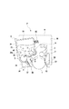
図2は、プロセスカートリッジP(PY・PM・PC・PK)の概略断面図である。図3は、プロセスカートリッジP(PY・PM・PC・PK)の概略斜視図である。図4は、プロセスカートリッジP(PY・PM・PC・PK)の概略分解斜視図である。 FIG. 2 is a schematic sectional view of the process cartridge P (PY / PM / PC / PK). FIG. 3 is a schematic perspective view of the process cartridge P (PY / PM / PC / PK). FIG. 4 is a schematic exploded perspective view of the process cartridge P (PY / PM / PC / PK).
図3に示すように、プロセスカートリッジP(PY・PM・PC・PK)は、感光体ドラム1の回転軸線Tの方向を長手方向とする横長の形状であり、画像形成装置本体正面から見て右側が駆動側、左側が非駆動側である。カートリッジPは、感光体ドラムユニット8と、現像装置9と、駆動側カバー部材61と、非駆動側カバー部材62を有する。
As shown in FIG. 3, the process cartridge P (PY / PM / PC / PK) has a horizontally long shape whose longitudinal direction is the direction of the rotation axis T of the photosensitive drum 1, and is viewed from the front of the image forming apparatus main body. The right side is the driving side and the left side is the non-driving side. The cartridge P includes a
感光体ドラムユニット8は、少なくとも、クリーニングブレード2、すくいシート52を有するクリーニング枠体50と、感光体ドラム1と、帯電ローラ3により構成される。
The
図3、図4に示すように、感光体ドラム1は、駆動側は駆動側カバー部材61の感光体ドラム支持部61a、また、非駆動側は、非駆動側カバー部材62の回転軸線T上の感光体ドラム支持部62aによって回転自在に支持されている。感光体ドラム1の駆動側の端部には、感光体ドラム駆動入力部としてのドラム駆動カップリング(駆動伝達部)1aが感光体ドラム1と同心に取り付けてある。このドラム駆動カップリング1aに対して装置本体側のドラム駆動出力部としてのカップリング(不図示)が係合する。そして、装置本体の駆動モータ(不図示)の駆動力の伝達がなされ、感光体ドラム1がA方向(図1、図2)に所定の速度で回転駆動される。
As shown in FIGS. 3 and 4, the photosensitive drum 1 is driven on the photosensitive
帯電ローラ3は、感光体ドラム1に接触し従動回転する接触帯電方式の帯電部材である。そして、帯電ローラ3は駆動側と非駆動側の軸端部をクリーニング枠体50の側板間に設けられた軸受部(不図示)を介して回転自在に支持させて配設してある。
The charging
クリーニング部材であるクリーニングブレード2は弾性ゴムブレードであり、感光体ドラム1に残留したトナーを除去する役目をする。このクリーニングブレード2により感光体ドラム1の周面から除去された転写残トナーは、可撓性シート部材であるすくいシート52にガイドされてクリーニング枠体50の内部に位置する廃トナー室51に収容される。
The
ここで、すくいシート52は、クリーニング枠体50に設けられた座面53に一端側を両面テープによって貼り付けられて固定されている。そして他端側は、感光体ドラム1に対して接触している。接触する方向は、感光体ドラム1の回転方向Aに対して順方向になるように設定されている。これは、回転方向Aに回転する感光体ドラム1上の残トナーは、感光体ドラム1とすくいシート52との接触部をすり抜る。しかし、クリーニングブレード2により感光体ドラム1の周面から除去された残トナーを、回転方向Aとは反対の方向に移動するのを阻止する為である。
Here, the
現像装置9は、図3に示すように、現像剤担持体としての現像ローラ4の回転軸方向を長手方向とする横長の形状である。そして、現像ローラ4の他に、現像枠体30、現像ブレード6、現像剤供給ローラ5、端部シール部材36、可撓性シート部材である吹き出し防止シート37によって主に構成される。現像剤供給ローラ5は金属製の芯材と発泡ウレタン製の円筒状弾性体で構成されており、トナー室31の開口部31aに面した現像室33に配置され、現像ローラ4と当接している。現像ローラ4と現像剤供給ローラ5の芯材は、各々、現像室33に配置され、各々の両端部は現像枠体30の駆動側と非駆動側の両側面に取り付けられた軸受部材44、45によって回転自在に支持されている。
As shown in FIG. 3, the developing device 9 has a horizontally long shape in which the rotation axis direction of the developing
現像ローラ4と現像剤供給ローラ5は、駆動入力部75によって、装置本体側の現像駆動出力部としてのカップリング(不図示)が係合して装置本体の駆動モータ(不図示)の駆動力の伝達がなされ、各々C、D方向に所定の速度で回転駆動される。
The developing
現像時には、現像剤供給ローラ5が回転して現像ローラ4と摺擦することで、現像枠体30におけるトナー室31のトナー70を、現像室33内で現像ローラ4上に担持させる。現像ブレード6は、先端部を現像ローラ4の回転方向に対してカウンター方向に現像ローラ4に当接させて配設している。現像ローラ4上に担持されたトナーは、現像ローラ4の回転に伴い現像ブレード6によって電荷を付与されるとともに、所定のトナー薄層に規制される。そして現像ローラ4と感光体ドラム1の接触部で現像ローラ4上のトナーが感光体ドラム1上の静電潜像に付着し、潜像を現像する。
At the time of development, the
現像に寄与せず、現像ローラ4上に残留したトナーは、現像ローラ4の回転によって、現像室33内に戻され、現像剤供給ローラ5との摺擦部で現像ローラ4から剥離、回収される。回収されたトナーは、現像室33で残りのトナーと混合される。
The toner that does not contribute to the development and remains on the developing
現像室33の開口部の両端には、現像ローラ4と当接した状態で、端部シール部材40が配置され、現像ブレード6および現像ローラ4と、現像室33との隙間からのトナー漏れを防止している。また、現像室33の開口部の長手方向には、吹き出し防止シート37が現像ローラ4と当接するように配置され、現像室33と現像ローラ4と間のトナー漏れを防止している。即ち、ここで、吹き出し防止シート37は、現像枠体30に設けられた座面32に一端側を両面テープによって貼り付けられて固定されている。そして他端側は、現像ローラ4に対して接触している。
また、図3に示すように、現像装置9は、駆動側カバー部材61と非駆動側カバー部材62の間においてドラム軸線Tと並行な軸線Vを中心にして揺動自在に支持されている。現像装置9の駆動側は、現像サイドカバー48の円筒部分48aが、駆動側カバー部材61の円筒受け穴61bに回転可能に支持されて揺動中心となっている。非駆動側は、現像枠体30における側面の穴(不図示)が、非駆動側カバー部材62の軸62bに回転可能に支持されて揺動中心となっている。即ち、現像装置9は、感光体ドラムユニット8と回転可能に結合されており、現像ローラ4が感光体ドラム1に接触する方向に回動するように、付勢部材である加圧バネ90によって常に付勢されている。加圧バネ90は非駆動側、駆動側の両側に配置されている。即ち、現像装置9は、現像ローラ4を感光体ドラム1に接触させる接触位置と、現像ローラ4を感光体ドラム1から離間させる離間位置との間を移動可能である。
As shown in FIG. 3, the developing device 9 is supported between the driving-
本発明の実施例である保護部材(以下、ドラム保護カバーと称す)について、図5、図6、図7、図8、図9を用いて説明する。 A protective member (hereinafter referred to as a drum protective cover) that is an embodiment of the present invention will be described with reference to FIGS. 5, 6, 7, 8, and 9.
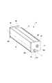
図5は、ドラム保護カバーの概略斜視図である。図6は、ドラム保護カバー装着時におけるプロセスカートリッジの断面図である。図7は、ドラム保護カバー装着時における感光体ドラムユニット側から見たプロセスカートリッジの概略斜視図ある。図8は、ドラム保護カバー装着時における現像装置側から見たプロセスカートリッジの概略斜視図ある。図9は、ドラム保護カバー装着時におけるプロセスカートリッジの概略断面図(実施例2)である。 FIG. 5 is a schematic perspective view of the drum protection cover. FIG. 6 is a cross-sectional view of the process cartridge when the drum protective cover is mounted. FIG. 7 is a schematic perspective view of the process cartridge as viewed from the photosensitive drum unit side when the drum protective cover is attached. FIG. 8 is a schematic perspective view of the process cartridge as viewed from the developing device side when the drum protective cover is mounted. FIG. 9 is a schematic cross-sectional view (Example 2) of the process cartridge when the drum protective cover is mounted.
まずは、ドラム保護カバーについて、図4、図5を用いて説明する。ドラム保護カバー80は、樹脂で成型されたものであり、通常は、出荷時や回収時に、感光体ドラム表面を光、ゴミ、ケバ、傷等から保護する役目を果たす。
First, the drum protective cover will be described with reference to FIGS. The
プロセスカートリッジPを画像形成装置本体100に装着して使用する際、ドラム保護カバー80は、ユーザーが手がかり部83を下方向に押すことで、外すことができる。
When the process cartridge P is mounted on the image forming apparatus
ドラム保護カバー80のプロセスカートリッジPに対する固定方法を説明する。ドラム保護カバー80の係合部86は駆動側カバー部材61の係合穴61cと、また、係合部87は非駆動側カバー部材62の係合穴62cと各々係合し、短手方向(図6のW方向)の位置が決まる。さらに、係合部88、89が、クリーニング枠体50の係合穴50c、50dと各々係合することで、上下方向(図6のU方向)の位置が決まる。本実施例とは別に、感光体ドラム1を支持する部分のみをカバー部材で構成して、上記係合穴を、全てクリーニング枠体50に設けても構わない。
A method for fixing the
本実施例では、現像ローラ4と感光体ドラム1が離間した状態で出荷する形態を採用している。図6に示すように、ドラム保護カバー80を装着したときに、現像装置位置決め部84、85が、現像装置9の軸受部材44、45の一部に当接する。このとき、現像装置9は揺動中心に対して、一定角度だけ時計方向に回転した状態で保持され、感光体ドラム1と現像ローラ4が離間した状態になる。即ち、現像装置9は離間位置に位置する。
In this embodiment, a configuration is adopted in which the developing
本実施例における離間状態は、現像位置決め部84、85と感光体ドラム1が接触しない状態であるが、感光体ドラム1と現像装置9の軸受部材44、45の両方に接触した状態で離間させても構わない。
The separation state in this embodiment is a state in which the
従来においては、出荷時や回収時、輸送時の衝撃等により、吹き出し防止シート座面32、すくいシート座面53が変形することで、容器内の内圧が上昇する。そして、吹き出し防止シート座面32、すくいシート座面53の位置が元に戻った際、上昇した内圧が当接圧の小さい吹き出し防止シート37、すくいシート52からトナーが漏れる可能性があった。
Conventionally, the blowout prevention
よって、トナー漏れ対策として、出荷時、回収時のみに装着するドラム保護カバー80に、各シート部材の座面の変形を防止する機能を持たせることが、簡易であり効果的である。
Therefore, as a countermeasure against toner leakage, it is simple and effective to provide the
図8に示すように、現像装置9における現像枠体30は、吹き出し防止シート座面32の変形対策として、座面の裏側32bに対して、垂直である複数の補強リブ34を現像ローラ軸線方向(図中T方向)に並んで配設している。本実施例では、各リブの間の座面の裏側32bに、直接、押え部82を当接させている。具体的には、リブ34aと34bとの間に押え部82a、リブ34bと34cの間に押え部82b、リブ34cと34dの間に押え部82c、リブ34dと34eの間に押え部82d、リブ34eと34fの間に押え部82eを設けている。押え部82は、弾性部となっているため、座面の裏側32bの寸法バラツキを吸収できる。
As shown in FIG. 8, the developing
感光体ドラムユニット8も、図7に示すように、回収時における、すくいシート座面53の変形対策として、押え部81を座面の裏側53bに当接させる。押え部81は、弾性部となっているため、座面の裏側53bの寸法バラツキを吸収できる。実施例では、押え部81a、81b、81c、81d、81eと分割されているが、弾性があれば、一体化しても構わない。
As shown in FIG. 7, the
本実施例では、すくシート座面53の座面の裏側53bには、リブを設けていない。しかし、リブを設けた場合でも、現像装置9と同様、各リブ間の座面の裏側53bに対応するよう、押え部81a、81b、81c、81d、81eを当接させれば、同様の効果が得られる。
In this embodiment, ribs are not provided on the
本実施例では、各リブ間に押え部82を設けたが、図9に示すように、座面の裏側32bから直接配接された各リブの天面35に押え部82を当接させても同様の効果を得られる。このとき、複数のリブ34の間隔が小さければ小さいほど、より効果的である(実施例2)。
In this embodiment, the
また、上述したように、座面の裏側32bを直接押さえない場合は、座面32を形成する部分の根元36よりも座面先端側に押え部82を当接する方が効果的である。
Further, as described above, when the
感光体ドラムユニット8でも、図9に示すように、リブ天面54に押え部81を当接させても同様の効果を得られる。座面の裏側53bを直接押さえない場合は、座面53を形成する部分の根元55よりも座面先端側に押え部81を当接させた方が効果的である。
Even in the
この場合、複数のリブ間に合わせて、押え部を複数形成する必要がなく、押え部の位置、押え部の数の自由度が増すこととなる。 In this case, it is not necessary to form a plurality of pressing portions in accordance with the plurality of ribs, and the degree of freedom of the position of the pressing portion and the number of the pressing portions is increased.
本実施例では、少なくとも感光体ドラム1と帯電ローラ3を含む感光体ドラムユニット8と、少なくとも現像ローラ4を含む現像装置9とが、一体化したプロセスカートリッジ構成となっている。しかし、感光体ドラムユニット8と現像装置9を独立した構成の場合でも、本実施例と同様の効果を得ることができる。
In this embodiment, the
例えば、独立した現像装置の場合、現像ローラの保護カバーを、現像装置9における軸受部材45と現像サイドカバー48に対して位置決めし、吹き出し防止シート座面に押え部を当接させる構成である。このとき、現像枠体50に対して位置決めしても構わない。
For example, in the case of an independent developing device, the protective cover of the developing roller is positioned with respect to the bearing
また、独立した感光体ドラムユニットの場合は、ドラム保護カバーを、感光体ドラムユニットに対して位置決めし、すくいシート座面に押え部を当接させる構成である。 In the case of an independent photoconductor drum unit, the drum protection cover is positioned with respect to the photoconductor drum unit, and the press portion is brought into contact with the rake sheet seat surface.
なお、本実施例では、感光体ドラム1と現像ローラ4が離間した状態を前提に説明したが、離間しない状態でも同様の効果を得ることができる。
In this embodiment, the description has been made on the assumption that the photosensitive drum 1 and the developing
例えば、前述したように、ドラム保護カバー80は、感光体ドラムユニット8を構成するクリーニング枠体50、駆動側カバー部材61、非駆動側カバー部材62によって、位置が決まる。離間しない状態では、ドラム保護カバー80に、現像位置決め部84、85は不要であり、このとき、現像装置9は揺動中心に回転し、現像ローラ4が感光体ドラム1に突き当たることで位置が決まる。そして、ドラム保護カバーの押え部82は、吹き出し防止シート座面32の座面の裏側32bに当接する。
For example, as described above, the position of the
1 感光体ドラム
1a ドラム駆動カップリング
2 クリーニングブレード
3 帯電ローラ
4 現像ローラ
5 現像剤供給ローラ
8 感光体ドラムユニット
9 現像装置
30 現像枠体
31 トナー室
31a 開口部
32 吹き出し防止シート座面
32b 座面の裏側
33 現像室
34(34a、34b、34c、34d、34e、34f) リブ
35 リブ天面
36 根元
37 吹き出し防止シート
40 端部シール部材
48 現像サイドカバー
48a 円筒部分
50 クリーニング枠体
50c 係合穴
50d 係合穴
51 廃トナー室
52 すくいシート
53 すくいシート座面 53b:座面の裏側
54 リブ天面
55 根元
70 トナー
75 駆動入力部
80 ドラム保護カバー
81(81a、81b、81c、81d、81e) 押え部
82(82a、82b、82c、82d、82e) 押え部
83 手がかり部
84 現像位置決め部
85 現像位置決め部
86 係合部
87 係合部
88 係合部
89 係合部
90 加圧バネ
100 画像形成装置本体
102 カートリッジ収容部
105 レーザスキャナユニット
P(PY、PM、PC、PK) プロセスカートリッジ
S 紙
DESCRIPTION OF SYMBOLS 1
Claims (6)
静電潜像を形成する電子写真感光体と、
前記電子写真感光体を支持するクリーニング枠体と、
前記静電潜像を現像剤を用いて現像する現像剤担持体と、
前記現像剤担持体を支持する現像枠体と、
前記現像剤担持体と前記現像枠体の間から現像剤が漏れるのを防止するために、前記現像枠体に設けられた座面に一端側を固定され、他端側が前記現像剤担持体と接触する可撓性シート部材と、
前記電子写真感光体を保護するために前記クリーニング枠体に取り付けられ、前記プロセスカートリッジが前記電子写真画像形成装置に装着される際は取り外される保護部材であって、前記座面の変形を抑えるために前記座面の裏側に当接する押え部を有する保護部材と、
有することを特徴とするプロセスカートリッジ。 In a process cartridge detachable from an electrophotographic image forming apparatus,
An electrophotographic photoreceptor for forming an electrostatic latent image;
A cleaning frame for supporting the electrophotographic photosensitive member;
A developer carrier for developing the electrostatic latent image using a developer;
A developing frame for supporting the developer carrying member;
In order to prevent the developer from leaking between the developer carrying member and the developing device frame, one end side is fixed to a seating surface provided on the developing device frame, and the other end side is connected to the developer carrying member. A flexible sheet member in contact;
A protective member that is attached to the cleaning frame to protect the electrophotographic photosensitive member and is removed when the process cartridge is mounted on the electrophotographic image forming apparatus, and suppresses deformation of the seating surface. A protective member having a presser portion that contacts the back side of the seat surface;
A process cartridge comprising:
静電潜像を形成する電子写真感光体と、
前記電子写真感光体を支持するクリーニング枠体と、
前記電子写真感光体から現像剤を除去するクリーニング部材と、
前記クリーニング部材で除去された現像剤を前記クリーニング枠体の内部へガイドする可撓性シート部材であって、前記クリーニング枠体に設けられた座面に一端側を固定され、他端側が前記電子写真感光体と接触する可撓性シート部材と、
前記電子写真感光体を保護するために前記クリーニング枠体に取り付けられ、前記プロセスカートリッジが前記電子写真画像形成装置に装着される際は取り外される保護部材であって、前記座面の変形を抑えるために前記座面の裏側に当接する押え部を有する保護部材と、
を有することを特徴とするプロセスカートリッジ。 In a process cartridge that is detachable from an electrophotographic image forming apparatus,
An electrophotographic photoreceptor for forming an electrostatic latent image;
A cleaning frame for supporting the electrophotographic photosensitive member;
A cleaning member for removing the developer from the electrophotographic photoreceptor;
A flexible sheet member for guiding the developer removed by the cleaning member to the inside of the cleaning frame body, one end side being fixed to a seating surface provided in the cleaning frame body, and the other end side being the electron A flexible sheet member in contact with the photographic photoreceptor;
A protective member that is attached to the cleaning frame to protect the electrophotographic photosensitive member and is removed when the process cartridge is mounted on the electrophotographic image forming apparatus, and suppresses deformation of the seating surface. A protective member having a presser portion that contacts the back side of the seat surface;
A process cartridge comprising:
Priority Applications (2)
| Application Number | Priority Date | Filing Date | Title |
|---|---|---|---|
| JP2010139961A JP5550462B2 (en) | 2010-06-18 | 2010-06-18 | Process cartridge |
| US13/161,274 US8971753B2 (en) | 2010-06-18 | 2011-06-15 | Process cartridge |
Applications Claiming Priority (1)
| Application Number | Priority Date | Filing Date | Title |
|---|---|---|---|
| JP2010139961A JP5550462B2 (en) | 2010-06-18 | 2010-06-18 | Process cartridge |
Publications (3)
| Publication Number | Publication Date |
|---|---|
| JP2012003160A JP2012003160A (en) | 2012-01-05 |
| JP2012003160A5 JP2012003160A5 (en) | 2013-08-01 |
| JP5550462B2 true JP5550462B2 (en) | 2014-07-16 |
Family
ID=45328793
Family Applications (1)
| Application Number | Title | Priority Date | Filing Date |
|---|---|---|---|
| JP2010139961A Expired - Fee Related JP5550462B2 (en) | 2010-06-18 | 2010-06-18 | Process cartridge |
Country Status (2)
| Country | Link |
|---|---|
| US (1) | US8971753B2 (en) |
| JP (1) | JP5550462B2 (en) |
Families Citing this family (5)
| Publication number | Priority date | Publication date | Assignee | Title |
|---|---|---|---|---|
| JP5919766B2 (en) * | 2011-11-30 | 2016-05-18 | ブラザー工業株式会社 | Process cartridge |
| JP6112845B2 (en) * | 2012-02-28 | 2017-04-12 | キヤノン株式会社 | Cleaning device, developing device, process cartridge, and image forming apparatus |
| JP2015049422A (en) * | 2013-09-03 | 2015-03-16 | キヤノン株式会社 | Image carrier unit and image forming apparatus |
| JP6529282B2 (en) * | 2015-02-27 | 2019-06-12 | キヤノン株式会社 | Side member and cartridge, and image forming apparatus |
| JP6766523B2 (en) * | 2016-08-24 | 2020-10-14 | 富士ゼロックス株式会社 | Develop equipment, process cartridge and image forming equipment |
Family Cites Families (14)
| Publication number | Priority date | Publication date | Assignee | Title |
|---|---|---|---|---|
| JP2948238B2 (en) * | 1989-08-29 | 1999-09-13 | キヤノン株式会社 | Developing device |
| JPH0619230A (en) * | 1992-06-30 | 1994-01-28 | Canon Inc | Process cartridge and image forming device |
| JP3507227B2 (en) | 1995-10-26 | 2004-03-15 | キヤノン株式会社 | Process cartridge and electrophotographic image forming apparatus |
| JP2000019839A (en) | 1998-06-30 | 2000-01-21 | Fuji Xerox Co Ltd | Rotary developing device |
| JP2000181328A (en) * | 1998-12-17 | 2000-06-30 | Canon Inc | Locking member, process cartridge and electrophotographic image forming device |
| JP2003015391A (en) * | 2001-06-29 | 2003-01-17 | Fuji Xerox Co Ltd | Developer housing structure |
| JP2004280012A (en) * | 2003-03-19 | 2004-10-07 | Canon Inc | Process cartridge |
| JP4407207B2 (en) * | 2003-08-25 | 2010-02-03 | 村田機械株式会社 | Developer and image forming apparatus having the same |
| JP2005227318A (en) * | 2004-02-10 | 2005-08-25 | Canon Inc | Process cartridge and image forming apparatus |
| JP4341619B2 (en) * | 2005-07-08 | 2009-10-07 | ブラザー工業株式会社 | Developer cartridge |
| JP4871614B2 (en) * | 2006-03-03 | 2012-02-08 | キヤノン株式会社 | Process cartridge and electrophotographic image forming apparatus |
| JP4663801B2 (en) * | 2008-09-01 | 2011-04-06 | キヤノン株式会社 | Process cartridge and image forming apparatus |
| JP4663802B2 (en) * | 2008-09-01 | 2011-04-06 | キヤノン株式会社 | Cover member and cartridge |
| JP5281534B2 (en) * | 2009-10-05 | 2013-09-04 | ホシデン株式会社 | Terminal box |
-
2010
- 2010-06-18 JP JP2010139961A patent/JP5550462B2/en not_active Expired - Fee Related
-
2011
- 2011-06-15 US US13/161,274 patent/US8971753B2/en not_active Expired - Fee Related
Also Published As
| Publication number | Publication date |
|---|---|
| US20110311265A1 (en) | 2011-12-22 |
| US8971753B2 (en) | 2015-03-03 |
| JP2012003160A (en) | 2012-01-05 |
Similar Documents
| Publication | Publication Date | Title |
|---|---|---|
| EP1939697B1 (en) | Electrophotographic image forming apparatus and process cartridge | |
| US7567769B2 (en) | Electrophotographic color image forming apparatus | |
| EP2100195B1 (en) | Process cartridge and electrophotographic image forming apparatus | |
| US8139979B2 (en) | Process cartridge and electrophotographic image forming apparatus | |
| US8583001B2 (en) | Developing device and process cartridge | |
| JP5953841B2 (en) | Image forming apparatus | |
| JP5546187B2 (en) | Image forming apparatus | |
| JP4366442B2 (en) | Process cartridge and electrophotographic image forming apparatus | |
| JP2010060613A (en) | Drum cartridge and electrophotographic image-forming apparatus | |
| JP5550462B2 (en) | Process cartridge | |
| US8918014B2 (en) | Electrophotographic image forming apparatus | |
| JP4463083B2 (en) | Color image forming apparatus | |
| US20110103825A1 (en) | Electrophotographic image forming apparatus | |
| JP6921545B2 (en) | Image forming device | |
| US20110103826A1 (en) | Electrophotographic image forming apparatus | |
| JPH11231595A (en) | Image forming device | |
| JP5317796B2 (en) | Image forming apparatus | |
| JP2010204287A (en) | Color electrophotographic image forming apparatus | |
| JPH0619256A (en) | Image recorder | |
| JPH04366855A (en) | Image forming device | |
| JP2021051224A (en) | Storage container and image forming apparatus | |
| JPH04367869A (en) | Image forming device | |
| JP2005292439A (en) | Image forming apparatus |
Legal Events
| Date | Code | Title | Description |
|---|---|---|---|
| A521 | Written amendment |
Free format text: JAPANESE INTERMEDIATE CODE: A523 Effective date: 20130617 |
|
| A621 | Written request for application examination |
Free format text: JAPANESE INTERMEDIATE CODE: A621 Effective date: 20130617 |
|
| TRDD | Decision of grant or rejection written | ||
| A01 | Written decision to grant a patent or to grant a registration (utility model) |
Free format text: JAPANESE INTERMEDIATE CODE: A01 Effective date: 20140422 |
|
| A61 | First payment of annual fees (during grant procedure) |
Free format text: JAPANESE INTERMEDIATE CODE: A61 Effective date: 20140520 |
|
| R151 | Written notification of patent or utility model registration |
Ref document number: 5550462 Country of ref document: JP Free format text: JAPANESE INTERMEDIATE CODE: R151 |
|
| LAPS | Cancellation because of no payment of annual fees |